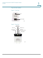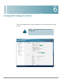
1
ADMINISTRATION
GUIDE
Cisco Small Business
Model PVC300
PTZ Internet Camera with Audio and PoE
6bZg^XVh=ZVYfjVgiZgh
8^hXdHnhiZbh!>cX#
HVc?dhZ!86
6h^VEVX^[^X=ZVYfjVgiZgh
8^hXdHnhiZbhJH6EiZ#AiY#
H^c\VedgZ
:jgdeZ=ZVYfjVgiZgh
8^hXdHnhiZbh>ciZgcVi^dcVa7K
6bhiZgYVb!I]ZCZi]ZgaVcYh
8^hXd]VhbdgZi]Vc'%%d[[^XZhldgaYl^YZ#6YYgZhhZh!e]dcZcjbWZgh!VcY[VmcjbWZghVgZa^hiZYdci]Z8^hXdLZWh^iZVilll#X^hXd#Xdb$\d$d[[^XZh#
889:!88:CI!8^hXd:dh!8^hXdAjb^c!8^hXdCZmjh!8^hXdHiVY^jbK^h^dc!8^hXdIZaZEgZhZcXZ!i]Z8^hXdad\d!98:!VcYLZaXdbZidi]Z=jbVcCZildg`VgZigVYZbVg`h08]Vc\^c\i]ZLVnLZLdg`!A^kZ!EaVn!VcY
6bZg^XVh=ZVYfjVgiZgh
6h^VEVX^[^X=ZVYfjVgiZgh
:jgdeZ=ZVYfjVgiZgh
AZVgcVcY8^hXdHidgZVgZhZgk^XZbVg`h0VcY6XXZhhGZ\^higVg!6^gdcZi!6hncXDH!7g^c\^c\i]ZBZZi^c\IdNdj!8ViVanhi!8896!889E!88>:!88>E!88C6!88CE!88HE!88KE!8^hXd!i]Z8^hXd8Zgi^[^ZY>ciZgcZildg`
8^hXdHnhiZbh!>cX#
8^hXdHnhiZbhJH6EiZ#AiY#
8^hXdHnhiZbh>ciZgcVi^dcVa7K
:meZgiad\d!8^hXd>DH!8^hXdEgZhh!8^hXdHnhiZbh!8^hXdHnhiZbh8Ve^iVa!i]Z8^hXdHnhiZbhad\d!8^hXdJc^in!8daaVWdgVi^dcL^i]djiA^b^iVi^dc!:i]Zg;Vhi!:i]ZgHl^iX]!:kZci8ZciZg!;VhiHiZe!;daadlBZ7gdlh^c\!
HVc?dhZ!86
H^c\VedgZ
6bhiZgYVb!I]ZCZi]ZgaVcYh
6bZg^XVh=ZVYfjVgiZgh
6h^VEVX^[^X=ZVYfjVgiZgh
:jgdeZ=ZVYfjVgiZgh
;dgbH]VgZ!<^\V9g^kZ!=dbZA^c`!>ciZgcZiFjdi^Zci!>DH!^E]dcZ!^F:meZgi^hZ!i]Z^Fad\d!^FCZiGZVY^cZhhHXdgZXVgY!^Fj^X`HijYn!>gdcEdgi!i]Z>gdcEdgiad\d!A^\]iHigZVb!A^c`hnh!BZY^VIdcZ!BZZi^c\EaVXZ!BZZi^c\EaVXZ
8^hXdHnhiZbh!>cX#
8^hXdHnhiZbhJH6EiZ#AiY#
8^hXdHnhiZbh>ciZgcVi^dcVa7K
8]^bZHdjcY!B<M!CZildg`Zgh!CZildg`^c\6XVYZbn!CZildg`GZ\^higVg!E8Cdl!E>M!EdlZgEVcZah!Egd8dccZXi!HXg^eiH]VgZ!HZcYZg7VhZ!HB6GIcZi!HeZXigjb:meZgi!HiVX`L^hZ!I]Z;VhiZhiLVnid>cXgZVhZNdjg>ciZgcZi
HVc?dhZ!86
H^c\VedgZ
6bhiZgYVb!I]ZCZi]ZgaVcYh
Fjdi^Zci!IgVchEVi]!LZW:m!VcYi]ZLZW:mad\dVgZgZ\^hiZgZYigVYZbVg`hd[8^hXdHnhiZbh!>cX#VcY$dg^ihV[[^a^ViZh^ci]ZJc^iZYHiViZhVcYXZgiV^cdi]ZgXdjcig^Zh#
8^hXd]VhbdgZi]Vc'%%d[[^XZhldgaYl^YZ#6YYgZhhZh!e]dcZcjbWZgh!VcY[VmcjbWZghVgZa^hiZYdci]Z8^hXdLZWh^iZVilll#X^hXd#Xdb$\d$d[[^XZh#
6aadi]ZgigVYZbVg`hbZci^dcZY^ci]^hYdXjbZcidgLZWh^iZVgZi]ZegdeZgind[i]Z^ggZheZXi^kZdlcZgh#I]ZjhZd[i]ZldgYeVgicZgYdZhcdi^beanVeVgicZgh]^egZaVi^dch]^eWZilZZc8^hXdVcYVcndi]ZgXdbeVcn#%-%,G
889:!88:CI!8^hXd:dh!8^hXdAjb^c!8^hXdCZmjh!8^hXdHiVY^jbK^h^dc!8^hXdIZaZEgZhZcXZ!i]Z8^hXdad\d!98:!VcYLZaXdbZidi]Z=jbVcCZildg`VgZigVYZbVg`h08]Vc\^c\i]ZLVnLZLdg`!A^kZ!EaVn!VcY
Xd]VhbdgZi]Vc'%%d[[^XZhldgaYl^YZ#6YYgZhhZh!e]dcZcjbWZgh!VcY[VmcjbWZghVgZa^hiZYdci]Z8^hXdLZWh^iZVilll#X^hXd#Xdb$\d$d[[^XZh#
© 2011 Cisco Systems, Inc. All rights reserved.
OL-18044-02
Contents
Getting Started
6
Chapter 1: Getting to Know the PVC300 PTZ Internet Camera
7
Overview
Physical Description
7
8
Digital Input Digital Output Diagram
10
Hardware Reset
11
Camera Usage Notes
11
11
Chapter 2: Installing The Camera
Incorrect
12
Correct12
Camera Installation
13
Network Deployment
15
Basic Ethernet Setup
15
Power over Ethernet (PoE) Setup
15
Installing the Software
18
Installing the Setup Wizard
18
Running the Setup Wizard to Install the Camera Software
19
Chapter 3: Accessing the PVC300 PTZ Internet Camera
22
Using Web Browsers
22
Using RTSP Players
23
Using 3GPP-Compatible Mobile Devices
25
Configuring Port Forwarding Rules
26
Chapter 4: The Camera’s Home Page
27
Menu
27
Camera Control Panel
27
Cisco Small Business Administration Guide for the Model PVC300 PTZ Internet Camera with Audio and PoE
3
Contents
Chapter 5: Configuring Client Settings
29
Chapter 6: Using the Setup Screen
31
Expanding the Setup Folder
32
Configuring Basic Settings
32
Device Settings
32
Network Settings
33
Configuring Advanced Camera Settings
34
HTTP
34
FTP
35
HTTPS
35
SIP
35
RTP/RTSP
36
Netfilter
38
HTTPS
39
Enable HTTPS
39
Certificate Information
40
Discovery Setting
40
UPnP Settings
40
QoS
41
CoS
41
DSCP
41
Administering the PVC300
42
Defining User Settings
42
Defining Camera Maintenance Settings
43
Upgrading the Firmware
44
Configuring Audio, Video, and Camera Controls
45
Defining Image Settings
45
Setting Camera Audio Functions
47
Setting Camera Control Options
49
Configuring Camera Applications
Cisco Small Business Administration Guide for the Model PVC300 PTZ Internet Camera with Audio and PoE
51
4
Contents
Applications
51
Enabling Motion Detection
57
Configuring Video Recording Settings
58
Configuring DDNS for the Camera
60
I/O Ports
60
Viewing Camera Status
61
Viewing System Information
61
Viewing Image Settings
61
Viewing Network Settings
61
Viewing the System Log
62
Appendix A: Troubleshooting
63
Windows Help
65
TCP/IP
65
Shared Resources
65
Network Neighborhood/My Network Places
65
Appendix B: Specifications
PVC300
Appendix C: Support Contacts
Cisco Small Business Administration Guide for the Model PVC300 PTZ Internet Camera with Audio and PoE
66
66
68
5
Preface
Getting Started
This guide describes how to install, configure, and use the PVC300 PTZ Internet
camera.
For more information about advanced features of the camera not covered in this
document, see the Cisco Small Business Video Monitoring System
Administration Guide.
Cisco Small Business Administration Guide for the Model PVC300 PTZ Internet Camera with Audio and PoE
6
1
Getting to Know the PVC300 PTZ Internet
Camera
Overview
The PVC300 PTZ Internet Camera is equipped with a Sony progressive scan CCD
sensor and pan-tilt 2.6x optical zoom lens. It is a high-performance network
camera for indoor surveillance applications such as security for banks, retail
stores, or offices.
With progressive scan techniques, this network camera is an ideal choice to
provide clear, high-quality video, and capture ultra-smooth images of fast-moving
objects without any pixilated edges.
Built into the camera is a 2.6x motorized zoom module, which provides greater
depth of field when viewing near or distant objects. With a 350-degree horizontal
and 125-degree vertical range of capture, it effectively gives users a wide-area
view.
A Power over Ethernet connection helps reduce cabling problems and eases the
installation procedure. The PVC300 also comes with a 16-channel video
monitoring system software, which helps users to set up a powerful surveillance
system.
The PVC300 PTZ Internet Camera is not only a high-performance web-ready
camera but also can be part of a flexible surveillance system.
The PVC300 PTZ Internet Camera is a network device and its use should be
straightforward for those who have basic network knowledge. It is designed for
various applications such as video sharing, general security, and surveillance.
Cisco Small Business Administration Guide for the Model PVC300 PTZ Internet Camera with Audio and PoE
7
1
Getting to Know the PVC300 PTZ Internet Camera
Overview
Physical Description
Figure 1 Front Panel
Lens
272873
Status Display
Figure 2
Rear Panel
General I/O
Terminal Block
Audio Out
Power Cord
Socket
Microphone In
Ethernet
10/10 RJ45 Socket
272874
Reset Button
Cisco Small Business Administration Guide for the Model PVC300 PTZ Internet Camera with Audio and PoE
8
1
Getting to Know the PVC300 PTZ Internet Camera
Overview
Figure 3
Internal Microphone
272878
Internal
microphone
General I/O Terminal Block
The General I/O Terminal Block allows you to connect the camera to external
input/output devices.
The ports are numbered from 1 to 4. If you place the camera on a table and look at
the back side, port 1 is left-most port and port 4 is the right-most port.
The following table describes the ports:
Port #
Description
1
Power
12VDC +- 5% 1.5A max, Max rating 2.0A
2
Digital output
Max. 40 VDC, Max. 400mA, isolation 2kV
3
Digital input
Open/short-to-ground, isolation 2kV, internal pull-up
4
Ground
Cisco Small Business Administration Guide for the Model PVC300 PTZ Internet Camera with Audio and PoE
9
1
Getting to Know the PVC300 PTZ Internet Camera
Overview
Digital Input Digital Output Diagram
Pins 1 to 4 are used to connect with digital input and digital output devices. Refer
to the following illustration for the connection method.
The color of LEDs indicates the status of the PVC300 PTZ Internet Camera.
Status LED Color
Description
Blinking amber
Power is being supplied to the PVC300 PTZ
Internet Camera.
Solid green
The PVC300 PTZ Internet Camera is active.
Solid green with blinking
amber in between
The PVC300 PTZ Internet Camera is trying to
obtain an IP address.
Solid green and amber
An IP address is successfully assigned to the
PVC300 PTZ Internet Camera.
Solid amber with blinking
green in between
The PVC300 PTZ Internet Camera is working.
Blinking amber and green
The PVC300 PTZ Internet Camera is performing a
firmware upgrade.
Cisco Small Business Administration Guide for the Model PVC300 PTZ Internet Camera with Audio and PoE
10
Getting to Know the PVC300 PTZ Internet Camera
Camera Usage Notes
1
Hardware Reset
There is an indented reset button on the back panel of the PVC300 PTZ Internet
Camera. It is used to reboot the PVC300 PTZ Internet Camera or restore it to the
factory default. Sometimes rebooting the PVC300 PTZ Internet Camera can set it
back to normal state. If the problems remain after rebooting, restore the factory
default and install again.
Reboot—Press and release the indented reset button with a paper clip. Wait for
the PVC300 PTZ Internet Camera to reboot.
Restore—Press the indented reset button continuously for around 30 seconds
until the status LED rapidly blinks amber and green simultaneously. Note that all
settings will be restored to factory default.
Camera Usage Notes
The use of surveillance devices may be prohibited by law in your country. It is your
responsibility to ensure that the operation of such devices is legal before installing
this unit for its intended use. It is important to first verify that all contents received
are complete as listed in the Quick Start Guide.
Carefully read and follow the instructions in Chapter 2, “Installing The Camera,” to
avoid damages due to faulty assembly and installation. This also ensures the
product is used properly as intended.
Cisco Small Business Administration Guide for the Model PVC300 PTZ Internet Camera with Audio and PoE
11
2
Installing The Camera
This chapter describes how to install and configure the PVC300 PTZ Internet
Camera.
!
CAUTION Do not pick up the Cisco PVC300 IP camera from the top (head) when removing the
camera from the box or installing it. Rough treatment or turning the head manually
can result in damage to the camera.
Incorrect
Correct
Cisco Small Business Administration Guide for the Model PVC300 PTZ Internet Camera with Audio and PoE
12
2
Installing The Camera
Camera Installation
Camera Installation
Follow these steps to install your camera.
STEP 1
Attach a ceiling mount bracket (1) to the PVC300 PTZ Internet Camera and secure
it with two small screws (2).
271139
1
2
Cisco Small Business Administration Guide for the Model PVC300 PTZ Internet Camera with Audio and PoE
13
2
Installing The Camera
Camera Installation
STEP 2
Drill three pilot holes into the ceiling and hammer the plastic anchors (1) into the
holes. Fasten a ceiling mount bracket (2) to the ceiling with three screws (3).
1
2
271140
3
Slide the camera into the ceiling mount bracket.
STEP 4
Secure the two ceiling mount brackets with a small screw
271141
STEP 3
.
The camera is now ready for network connection.
Cisco Small Business Administration Guide for the Model PVC300 PTZ Internet Camera with Audio and PoE
14
2
Installing The Camera
Network Deployment
Network Deployment
There are two options for deploying the camera on the network:
•
Basic Ethernet Setup
•
Power over Ethernet (PoE) Setup
Basic Ethernet Setup
Follow these steps to perform basic Ethernet setup.
STEP 1
Connect the camera to a switch via the supplied Ethernet cable (1).
12V 1A
Power
SPKR Out
EXT I/O
Mic. In
Ethernet w/PoE
Reset
2
1
COLLISION
Ethernet
switch
STEP 2
1
2
3
4
5
LINK
RECEIVE
PARTITION
271142
POWER
Connect the supplied power cable (2) from the camera to a power outlet.
Power over Ethernet (PoE) Setup
There are two options for powering the camera over Ethernet:
•
Using a PoE-Enabled Router or Switch
•
Using a Non-PoE Router or Switch
Cisco Small Business Administration Guide for the Model PVC300 PTZ Internet Camera with Audio and PoE
15
2
Installing The Camera
Network Deployment
Using a PoE-Enabled Router or Switch
The PVC300 camera is PoE-compliant, which allows it to be powered via a single
Ethernet cable to a PoE-enabled broadband router or switch. A power adapter is
not required when powered through a PoE switch.
Follow this step to connect your camera to a PoE-enabled switch.
STEP 1
Connect the camera to the switch via an Ethernet cable.
12V 1A
Power
COLLISION
1
2
EXT I/O
Mic. In
Ethernet w/PoE
Reset
PoE switch
3
4
5
LINK
RECEIVE
PARTITION
271143
SPKR Out
POWER
Cisco Small Business Administration Guide for the Model PVC300 PTZ Internet Camera with Audio and PoE
16
2
Installing The Camera
Network Deployment
Using a Non-PoE Router or Switch
If your broadband switch or router does not support PoE, use a PoE power injector
(not included) to connect the camera to the broadband router or switch.
Follow these steps to connect your camera to a non-PoE-enabled switch through a
PoE power injector.
STEP 1
Connect the PoE power injector (1) to the camera using an Ethernet cable (2).
12V 1A
Power
SPKR Out
EXT I/O
Mic. In
Ethernet w/PoE
Reset
271144
2
1
3
POWER
COLLISION
1
2
3
4
5
LINK
RECEIVE
PARTITION
4
STEP 2
To access audio/video through the WAN, connect the broadband router or switch
to the PoE power injector using an Ethernet cable (3).
STEP 3
Connect the PoE power injector to power (4).
Congratulations! The camera is now ready for configuration.
Cisco Small Business Administration Guide for the Model PVC300 PTZ Internet Camera with Audio and PoE
17
2
Installing The Camera
Installing the Software
Installing the Software
There is a Setup Wizard software program packaged in the product CD, which
helps to set up your PVC300 PTZ Internet Camera in your network. There are two
ways to use the Wizard:
1. You can launch the Wizard from the CD without installing it. Launching from the
CD is useful if you do not want to install anything on you computer.
2. You can install the software on your computer (the installation process
described in this section). Installing it on your computer is useful if you will want
to install more cameras in the future, and don’t want to search for the CD.
Installing the Setup Wizard
Follow these steps to install the Setup Wizard.
STEP 1
Launch the Setup Wizard from the product CD. The Welcome screen appears.
STEP 2
Click Next to continue. The License Agreement screen appears.
STEP 3
Click I Agree if you agree and wish to proceed. The Choose Install Location
screen appears.
STEP 4
Select a location for the software installation, or accept the default location. Then,
click Install to continue.
After the Wizard has completed installing the software, the Completion screen
appears.
STEP 5
Select the check box to run the Setup Wizard and click Finish to continue.
Follow the instructions in the next section to configure and install the software for
the PVC300 PTZ Internet Camera.
Cisco Small Business Administration Guide for the Model PVC300 PTZ Internet Camera with Audio and PoE
18
2
Installing The Camera
Installing the Software
Running the Setup Wizard to Install the Camera Software
This section describes how to install and configure the camera software.
Configuring Basic Camera Settings
Follow these steps to install the PVC300 camera software and configure basic
camera settings:
STEP 1
Click Start on the Welcome screen of the Setup Wizard to start the installation
process. The License Agreement screen appears.
STEP 2
Click Next if you agree and wish to proceed. The Setup Wizard searches your
network for PVC300 cameras and displays a list of all cameras it found.
NOTE UPnP must be enabled on your network for the Setup Wizard to find your camera.
See instructions for enabling UPnP in Appendix A, “Troubleshooting.”
STEP 3
Highlight the camera you wish to configure and click Next to continue.
The Setup Wizard displays the System Settings screen. This screen lets you
configure the following settings:
•
Hostname—Enter a unique name for the camera, up to 15 characters in
length. Unique names are helpful when you are using multiple cameras on
the same network.
•
User name—Enter the default user name of admin.
•
Password/Confirm Password—Enter the default password of admin in
both fields.
•
Date—Enter the current date.
•
Time—Enter the current time.
•
Radio Buttons—Select one of the following options:
-
Keep current date and time
-
Synchronize with computer time
-
Set date and time manually
-
Synchronize to time server auto
Cisco Small Business Administration Guide for the Model PVC300 PTZ Internet Camera with Audio and PoE
19
2
Installing The Camera
Installing the Software
Proceed to the next section to continue camera configuration.
Configuring the Camera’s Network Settings
Follow these steps to configure the camera’s network settings.
STEP 1
To continue configuring the camera’s network settings, click Next. The Network
Settings screen appears.
STEP 2
Select one of the following options to assign an IP address to the camera:
•
Static IP address—Select this option to assign the camera a static IP
address.
•
Automatic Configuration DHCP—Select this option to assign the camera
an automatic IP address from a DHCP server on your network.
•
PPPoE—Select this option if using a PPPoE connection to access the
Internet to assign the camera an automatic IP address.
STEP 3
Click Next to continue. The IP Setting screen appears.
STEP 4
Make any changes appropriate for your camera to integrate into your network,
then click Next to continue.
STEP 5
Confirm the changes you are about to make by clicking OK on the confirmation
screen. The wizard will show an hourglass while it configures your camera.
The New Internet Camera Settings screen appears and displays the camera’s
settings.
STEP 6
Click Next to continue. A dialog box appears prompting you whether to change the
settings.
STEP 7
Click OK to continue. A dialog box appears informing you that your configuration
has been saved successfully.
STEP 8
Click OK to continue. The Congratulations screen appears.
STEP 9
Click Exit to automatically launch your default web browser and proceed to the
Home page of the camera.
Cisco Small Business Administration Guide for the Model PVC300 PTZ Internet Camera with Audio and PoE
20
2
Installing The Camera
Installing the Software
NOTE Microsoft Internet Explorer (IE) is the official supported browser for the Cisco
PVC300 IP camera.
STEP 10 In the login dialog box, enter admin in both the User name and Password fields.
STEP 11 The PVC300 home page opens. The camera installation procedure is now
complete.
You may now proceed with Chapter 3, “Accessing the PVC300 PTZ Internet
Camera.”
Cisco Small Business Administration Guide for the Model PVC300 PTZ Internet Camera with Audio and PoE
21
3
Accessing the PVC300 PTZ Internet Camera
This chapter explains how to access the PVC300 PTZ Internet Camera through
web browsers, RTSP players, and 3GPP-compatible mobile devices.
Using Web Browsers
Follow these steps to access your PVC300 camera from web browsers:
STEP 1
Launch Microsoft Internet Explorer. Microsoft Internet Explorer (IE) is the official
supported browser for the Cisco PVC300 IP cameras.
STEP 2
Type the IP address of the PVC300 PTZ Internet Camera in the address field and
then press Enter.
STEP 3
Enter your user name and password in the login window and click OK.
NOTE: By default, the PVC300 PTZ Internet
Camera is not password-protected. To prevent
unauthorized access, it is highly recommended
to set a password for the camera.
If you see a warning message prompting you about installing ActiveX Controls on
your system, click Yes.
If you see a dialog box indicating that your security settings prohibit running
ActiveX Controls, enable ActiveX Controls for your browser. To enable ActiveX
Controls:
a. Choose Tools > Internet Options > Security > Custom Level.
b. Under ActiveX controls and plug-ins > Automatic prompting for ActiveX
controls, select Enable.
Cisco Small Business Administration Guide for the Model PVC300 PTZ Internet Camera with Audio and PoE
22
Accessing the PVC300 PTZ Internet Camera
Using RTSP Players
3
c. Click OK.
If authentication succeeds, the camera’s Home page appears.
Using RTSP Players
To view the MPEG-4 streaming media using RTSP players, you can use one of the
following players that support RTSP streaming.
•
Apple QuickTime Player
•
RealPlayer
•
VLC Media Player (a free download from www.videolan.org)
•
Any other MPEG supportable player
To launch an RTSP player, perform the following:
STEP 1
Launch the RTSP player.
STEP 2
Choose File > Open URL. An URL dialog box will pop up.
STEP 3
Type the URL command in the text box.
The format is rtsp://<ip address>:<rtsp port>/<access name for
stream1 or stream2>
where stream1 and stream2 are live.sdp and live.sdp2 respectively.
Cisco Small Business Administration Guide for the Model PVC300 PTZ Internet Camera with Audio and PoE
23
Accessing the PVC300 PTZ Internet Camera
Using RTSP Players
3
The live video is displayed in your RTSP player.
Cisco Small Business Administration Guide for the Model PVC300 PTZ Internet Camera with Audio and PoE
24
3
Accessing the PVC300 PTZ Internet Camera
Using 3GPP-Compatible Mobile Devices
Using 3GPP-Compatible Mobile Devices
To view the streaming media through 3GPP-compatible mobile devices, make
sure the PVC300 PTZ Internet Camera can be accessed from the Internet. For
more information on how to set up the PVC300 PTZ Internet Camera over the
Internet, see Chapter 2, “Installing The Camera.”
To use this feature, check the following settings on your PVC300 PTZ Internet
Camera:
STEP 1
Because most players on 3GPP mobile phones do not support RTSP
authentication, make sure the authentication mode of RTSP streaming is set to
disable. For more information, see RTSP Streaming.
STEP 2
Since the 3G network bandwidth is limited, you cannot use large video size. Set
the video and audio streaming parameters as listed below.
Video Mode
MPEG-4
Frame Size
176x144
Maximum Frame Rate
5 fps
Intra frame period
1S
Video quality (Constant bit rate)
40 kbps
Audio Type (GSM_AMR)
12.2 kbps
STEP 3
Most ISPs and media players require port 554 to allow RTSP streaming. Set the
RTSP port to 554. For more information, see RTSP Streaming.
STEP 4
Launch the players on 3GPP-compatible mobile devices, (ex. Real Player). Type
the URL commands in the player. The format is rtsp://<public ip address
of your camera>:<rtsp port>/<access name for stream1 or
stream2>.
Cisco Small Business Administration Guide for the Model PVC300 PTZ Internet Camera with Audio and PoE
25
3
Accessing the PVC300 PTZ Internet Camera
Configuring Port Forwarding Rules
Configuring Port Forwarding Rules
There are some additional configuration settings to make in order
For 2-way audio over the Internet to work on your PVC300 camera, you need to
configure additional settings, as shown in the example in the following diagram.
Cameras accessed over the Internet that require 2-way audio must use a unique
RTSP port. Routers with Port Address Translation should map the same external
port as used on the inside LAN network.
In the above example, PVC300 #2 external <wan-ip>:8554 maps to internal
<lan-ip>:8554. Consult your network administrator for alternative port
suggestions. Port# 8554 is designated as an alternate RTSP port by the Internet
Assigned Numbers Authority (IANA).
NOTE: 2-way audio is not supported in HTTP
mode under Client Settings.
Cisco Small Business Administration Guide for the Model PVC300 PTZ Internet Camera with Audio and PoE
26
4
The Camera’s Home Page
This chapter explains the Home page of the PVC300 camera.
Menu
Home—Click to go to the main page view.
Client Settings—Click to access the Client Settings page.
Setup—Click to access the PVC300 PTZ Internet Camera configuration page.
Language—Click to choose a language for the displayed interface.
Camera Control Panel
Snapshot—Click to capture and save still images. The captured images will be
displayed in a pop-up window. Right-click the image and choose Save Picture As
to save it in JPEG (*.jpg) or BMP (*.bmp) format.
Output—Two buttons toggle the I/O ports Off and On.
Zoom—Click + to zoom in. Click - to increase the field of view (wide angle).
Pan—Click to start the auto pan. The camera starts by panning from the current
position to the leftmost position, then pans in the opposite direction to the
rightmost position, then pans back to the original position.
Patrol—Click to move the camera between the preset positions on the Patrol List.
After one patrol cycle, the camera returns to the original position.
Stop—Click to stop the auto Pan and auto Patrol function.
Pan /tilt control buttons—The direction buttons are for Left, Right, Up, Down, and
Home functions. The Home button centers the camera.
Cisco Small Business Administration Guide for the Model PVC300 PTZ Internet Camera with Audio and PoE
27
The Camera’s Home Page
Camera Control Panel
4
Pan /Tilt /Zoom speed—Adjust the speed of pan, tilt, and zoom.
Go to—Once the Administrator has determined the preset positions, you can aim
the camera using this control.
Cisco Small Business Administration Guide for the Model PVC300 PTZ Internet Camera with Audio and PoE
28
5
Configuring Client Settings
This chapter explains how to select the streaming source, transmission mode, and
saving options for your PVC300 camera. Please note that Microsoft Internet
Explorer (IE) is the official supported browser for the Cisco PVC300 IP camera. If
another browser is used, you may not be able to successfully set values on the
Client Settings screen.
NOTE: When completed with the settings on
this page, click Save to ensure all changes take
effect.
You can set these options on the Client Settings screen.
The PVC300 camera supports MPEG-4 and MJPEG streams. Follow these steps
to configure PVC300 streaming options.
STEP 1
Select Stream 1 or Stream 2 as the streaming source.
STEP 2
Select one of the following options to configure the MPEG-4 media options:
Video and Audio—Streams audio and video.
Video Only—Streams only video.
Audio Only—Streams only audio.
These options works only when the video mode is set to MPEG-4.
STEP 3
Select one of the following options to configure the MPEG-4 protocol options (the
options available to you depend on your network environment):
Cisco Small Business Administration Guide for the Model PVC300 PTZ Internet Camera with Audio and PoE
29
5
Configuring Client Settings
UDP Unicast—Allows for more real-time audio and video streams. However,
network packets may be lost due to network burst traffic and images may be
obscured. Activate UDP connection when occasions require time-sensitive
responses and the video quality is less important. Note that each unicast client
connecting to the server takes up additional bandwidth and the PVC300 PTZ
Internet Camera allows up to ten simultaneous accesses.
UDP Multicast—Allows multicast-enabled routers to forward network packets to
all clients requesting streaming media. This helps to reduce the network
transmission load of the PVC300 PTZ Internet Camera while serving multiple
clients at the same time.
NOTE To use this feature, you must configure the PVC300 PTZ Internet Camera to
enable multicast streaming.
TCP—Guarantees the complete delivery of streaming data and thus provides
better video quality. Due to the narrower bandwidth, you may notice a delay in the
real-time video when you choose TCP instead of UDP.
HTTP—Allows the same quality as TCP protocol. In some network environments,
you do not need to open a specific port for streaming when you choose HTTP. If
you are inside a firewall, use this protocol to allow the streaming data to come
through.
STEP 4
Configure the MPEG-4 saving options.
In the MP4 Saving Options section of the Client Settings screen, you can specify
the storage destination and file name.
Folder—Specifies where to store the recorded video files.
File Name Prefix—Specifies the text that precedes the video file name.
Add date and time suffix to the file name—Adds date and time to the file name
suffix. The format is YYYYMMDD_HHMMSS.
For example, consider the following filename:
CLIP_200801008_180853
The filename prefix is CLIP_ and the date and time suffix is 200801008_180853.
Cisco Small Business Administration Guide for the Model PVC300 PTZ Internet Camera with Audio and PoE
30
6
Using the Setup Screen
This section explains how to use the categories on the left menu of the Setup
screen.
NOTE: Only Administrators can access the
Setup page.
Cisco Small Business Administration Guide for the Model PVC300 PTZ Internet Camera with Audio and PoE
31
6
Using the Setup Screen
Expanding the Setup Folder
Expanding the Setup Folder
Click the Setup folder icon to access the Basic Setup, Advanced Setup, Netfilter,
and HTTPS pages.
Configuring Basic Settings
This section explains how to configure the basic settings for the PVC300 PTZ
Internet Camera. It contains the following three areas; Device Settings, UPnP, and
Network Settings. When completed with the settings on this page, click Save to
ensure your changes take effect.
Device Settings
This area contains the settings for the following:
Camera name—Set a desired name for the PVC300 PTZ Internet Camera. The text
will be displayed at the top of the main page.
Disable LED Operator—If you don’t want to let others know that the network
camera is on, you can select this option to turn off the LED illuminators. This
prevents the camera’s operation from being noticed.
Current Date/Time—Click Change to display a pop up a window for user to with
the following options:
•
Sync with PC
•
Manually set a new date and time
Time zone—Select your local time zone from the drop down list.
NTP server—Assign the IP address or domain name of the time-server. Leaving
the text box blank connects the PVC300 PTZ Internet Camera to the default timeservers.
Update interval—Select to update the time with the NTP server on an hourly, daily,
weekly, or monthly basis.
Cisco Small Business Administration Guide for the Model PVC300 PTZ Internet Camera with Audio and PoE
32
6
Using the Setup Screen
Configuring Basic Settings
Network Settings
This area contains the settings for the following:
Configuration Type—Two options are available.
If you are not sure of the IP Address it is best to choose “Obtain IP Address
Automatically (DHCP)”. If you know your network settings then select “Fixed IP
Address”. If you choose to obtain an IP Address automatically, then just click Save.
Otherwise you must fill in the boxes for IP Address, Subnet Mask, Gateway,
Primary DNS and Secondary DNS. If you know your WINS server addresses you
can add them but this is not required.
IP address—The IP Address for your camera will identify your camera on the
network.
Subnet mask—The subnet mask for your camera, depending on your network
settings. The default value is "255.255.255.0".
Gateway—The IP Address of the gateway router you are using with your camera.
Primary DNS—A primary domain name server that translates IP addresses to a
more user-friendly format This is usually assigned by your ISP.
Secondary DNS—A secondary domain name server to backup the primary
domain server.
Primary WINS—If you have this information please add it here, otherwise you can
leave it blank.
Secondary WINS—If you have this information please add it here, otherwise you
can leave it blank.
PPPoE—If you have a PPPoE account, put your username, password and service
name in the related boxes. The system will restart when any changes are made to
this page and saved.
Enable IPv6—If your network supports IPv6 addressing, check this box and then
fill in the related boxes with the optional information. Click the IPv6 Info button to
display the current configuration for IPv6.
Cisco Small Business Administration Guide for the Model PVC300 PTZ Internet Camera with Audio and PoE
33
Using the Setup Screen
Configuring Advanced Camera Settings
6
Configuring Advanced Camera Settings
This section explains how to configure the advanced settings for the PVC300 PTZ
Internet Camera. It is composed of the following five areas; HTTP, FTP, HTTPS, SIP,
and RTP/RTSP.
HTTP
Authentication—Depending on your network security requirements, the PVC300
PTZ Internet Camera provides two types of security settings for a HTTP
transaction: basic and digest. If basic authentication is selected, the password is
sent in plain text format; there can be potential risks of being intercepted. If digest
authentication is selected, user credentials are encrypted in MD5 algorithm and
thus provide better protection against unauthorized accesses.
HTTP port / Secondary HTTP port—By default, the HTTP port is set to 80 and the
secondary HTTP port is set to 8080. They can also be assigned another port
number between 1024 and 65535. If the ports are incorrectly assigned, the
following warning messages are displayed:
To access the PVC300 PTZ Internet Camera within a LAN, both the HTTP port and
secondary HTTP port can be used to access the camera. For example, when the
HTTP port is set to 80 and the secondary HTTP port is set to 8080, refer to the
following example for the PVC300 PTZ Internet Camera’s IP address.
In a LAN—http://192.168.4.160 or http://192.168.4.160:8080
Access name for stream 1 / Access name for stream 2: The access name is used
to differentiate the streaming source. This is useful when you need to use Mozilla
Firefox or Netscape to access the PVC300 PTZ Internet Camera. If the video mode
is set to JPEG, you will receive continuous JPEG pictures.
This technology, known as “server push”, allows the PVC300 PTZ Internet Camera
to feed live pictures to Mozilla Firefox and Netscape. Use the following format:
http://<ip address>/cgi-bin/viewer/<access name such as
video.jpg>
The following instructions are for when you set the access name for stream 1 to
video.mjpg:
Cisco Small Business Administration Guide for the Model PVC300 PTZ Internet Camera with Audio and PoE
34
6
Using the Setup Screen
Configuring Advanced Camera Settings
STEP 1
Launch Mozilla Firefox or Netscape.
STEP 2
In the Audio/Video/Camera section set the video mode to JPEG. See ”Configuring
Audio, Video, and Camera Controls” on page 45.
STEP 3
Type the URL command in the address field. Press Enter.
The JPEG images will be displayed in your web browser.
NOTE: Microsoft® Internet Explorer does not
support server push technology; therefore,
using http://<ip address>/<access name for
stream1 or stream2> will fail to access the
PVC300 PTZ Internet Camera.
NOTE: To use the HTTP authentication, make
sure that your have set a password for the
PVC300 PTZ Internet Camera first; see the
Security Section for details.
FTP
The FTP server allows the PVC300 PTZ Internet Camera to use the Installation
Wizard to upgrade firmware. By default, the FTP port is set to 21. It can be
assigned another port number between 1024 and 65535.
HTTPS
Default is 443, can be changed to meet the needs of your network.
SIP
Default is 5060, can be changed to meet the needs of your network.
Cisco Small Business Administration Guide for the Model PVC300 PTZ Internet Camera with Audio and PoE
35
Using the Setup Screen
Configuring Advanced Camera Settings
6
RTP/RTSP
Authentication—The three authentication options are Disabled, Basic, and Digest.
•
The Disabled option allows an RTP/RTSP session without a username or
password.
•
The Basic option allows the username and password to be sent over the
network (in clear text).
•
The Digest option is an agreed upon method a web page can use to
negotiate credentials with a web user using the HTTP protocol. The Digest
authentication method is an application of MD5 cryptography.
Access name for stream 1—Specifies the access name for Stream 1. This name is
the access URL for accessing the camera from a client software (for example,
QuickTime Player) when the codec type is MPEG-4.
Access name for stream 2—Specifies the access name for Stream 1. This name is
the access URL for accessing the camera from a client software (for example,
QuickTime Player) when the codec type is MPEG-4.
RTSP port—Specifies the RTSP port. The default RTSP port is 554. You must
configure your router to forward traffic this port to your computer.
RTP port for video—The RTP (Real-time Transport Protocol) is used to deliver
video and audio data to the clients. By default, the RTP port for video is set to 5556
and the RTP port for audio is set to 5558.
RTCP port for video—The RTCP (Real-time Transport Control Protocol) allows the
PVC300 PTZ Internet Camera to transmit the data by monitoring Internet traffic
volume. By default, the RTCP port for video is set to 5557 and the RTCP port for
audio is set to 5559. It must be the port number of video RTP plus 1.
RTP port for audio—The audio channel port for RTP. It must be even number.
RTCP port for audio—The audio channel port for RTCP. It must be the port number
of audio RTP plus 1. You can modify the Multicast setting for stream1 and stream2.
You can reassign the five ports any value between 1024 and 65535. The RTP port
must be an even number and the RTCP port is the RTP port number plus one, and
thus always be odd. When the RTP port changes, the RTCP port will change
accordingly.
If the RTP ports are incorrectly assigned, a warning message is displayed.
Cisco Small Business Administration Guide for the Model PVC300 PTZ Internet Camera with Audio and PoE
36
6
Using the Setup Screen
Configuring Advanced Camera Settings
The five ports can be changed between 1024 and 65535. The multicast RTP port
must be an even number and the multicast RTCP port is multicast RTP port
number plus one, and thus is always odd. When the multicast RTP port changes,
the multicast RTCP port will change accordingly.
If the multicast RTP video ports are incorrectly assigned, a warning message is
displayed.
Multicast TTL— [1~255]:The multicast TTL (Time to live) is the value that tells the
router the range a packet can be forwarded.
NOTE: To use RTSP streaming authentication,
make sure you have set a password for the
PVC300 PTZ Internet Camera first.
Cisco Small Business Administration Guide for the Model PVC300 PTZ Internet Camera with Audio and PoE
37
6
Using the Setup Screen
Netfilter
Netfilter
The Netfilter controls the access permission of clients by checking the client IP
Address. Click on the check box Enable IP address filtering to enable Netfilter.
There are two options for permission control in the drop down menu: Allow and
Deny.
Only those clients whose IP address is in the Allowed List and not in the Denied
List can connect to the Video Server or PVC300 PTZ Internet Camera for receiving
the audio/video streaming. Both Allowed List and Denied List consist of a single IP
Address, list of IP Address ranges, or a network mask.
If you want to add a new IP address, click on the Add button and type the IP
Address you want to Allow or Deny. There are 3 methods of filtering in the drop
down menu: Single IP address, IP Address Range and Network.
If you want to add a new IP Address range, click on the Add button and type the
Begin IP Address on the left text box and End IP Address in the right text box. If
you want to add a new Network, click on the Add button and type the Network you
want to Allow or Deny.
If you want to remove an existing IP Address, IP address range, or Network, just
select from the pull-down menu and click on the Delete button. Both the Allowed
List and Denied List can have 10 entries.
Cisco Small Business Administration Guide for the Model PVC300 PTZ Internet Camera with Audio and PoE
38
6
Using the Setup Screen
HTTPS
HTTPS
HTTPS refers to the combination of HTTP interaction over an encrypted Secure
Socket Layer (SSL) or Transport Layer Security (TLS). The HTTPS technology
ensures end-to-end security and provides complete defense against eavesdrop,
impersonation, and hijacking.
Enable HTTPS
Click the “Enable HTTPS secure connection” checkbox to enable HTTPS. You will
first have to create and install a certificate.
Create and Install Certificate
The first method is to create a Self-signed certificate:
STEP 1
Click the Create button and the create Certificate window appears.
STEP 2
Fill in the required information and click Save to generate a self-signed certificate.
STEP 3
The certificate will be automatically installed upon generation, then you can
enable the HTTPS service.
The second method is to fill out a certificate request:
STEP 1
Click the Create button. The Create Certificate window appears.
STEP 2
Fill in information and click Save to generate a certificate request. A certificate
request will be generated by camera.
STEP 3
Copy the request and have Certificate Authority sign the certificate request.
STEP 4
The signed certificate will then be received in form of a file. You will need to
upload the certificate to the camera.
STEP 5
After uploading the signed certificate the camera will automatically install the
certificate. You can then enable the HTTPS service.
Cisco Small Business Administration Guide for the Model PVC300 PTZ Internet Camera with Audio and PoE
39
6
Using the Setup Screen
Discovery Setting
Certificate Information
Press the Property button to view the certificate details. After a certificate is
installed or generated you cannot generate a new one. The old certificate must be
removed before a new certificate can be generated. To remove the certificate,
press the Remove button. The same rule applies to certificate request. Users need
to remove the old certificate request to generate a new one.
Discovery Setting
UPnP Settings
UPnP is short for Universal Plug and Play, which is a networking architecture that
provides compatibility among networking equipment, software, and peripherals.
The PVC300 is a UPnP-enabled Internet camera and will only work with other
UPnP devices/software.
Enable UPnP Discovery—Select this option to enable UPnP discovery for your
PVC300 PTZ Internet Camera so that whenever a similar camera is added to the
network, shortcuts of connected PVC300 PTZ Internet Cameras show up at My
Network Places. Currently, UPnP is supported by Windows XP or later. To use this
feature, UPnP components must be enabled on your computer. See
Troubleshooting for more information.
Enable UPnP Traversal (Port Mapping)—To access the PVC300 PTZ Internet
Camera from the Internet, select this option to allow the camera to open ports on
the router automatically so that video streams can be sent out from a LAN. To use
of this feature, make sure that your router supports UPnP and it is activated. Your
router will also have to support NAT Traversal.
Enable UPnP AV—Enables the UPnP A/V service of the camera. UPnP A/V stands
for UPnP Audio and Video, which supports a variety of devices such as TVs, CD/
DVD players, or stereo systems. When enabled, it allows you to watch video clips
on a UPnP client, such as an iPod or Xbox.
Cisco Small Business Administration Guide for the Model PVC300 PTZ Internet Camera with Audio and PoE
40
6
Using the Setup Screen
QoS
QoS
CoS
Enable CoS—Set quality of service by creating a VLAN ID and a QoS priority. The
priority is from 0-7, where 7 is the highest. The default is 4. Remember to also make
all QoS settings on your switch.
DSCP
Enable DiffServ— Differentiated Services (DiffServ) is based on packet marking
and queuing disciplines. The marking is done by adding a field to the IP header,
called the DSCP (Differentiated Services Codepoint). This is a 6-bit field that
provides 64 different class IDs.
DSCP Priority Value—Describes a particular service level in terms of bandwidth,
queueing theory, and dropping (discarding the packet) decisions. Network
packets are classified according to their DSCP value and are given a particular
forwarding treatment; for example, the bandwidth required to reserve for the
packet. The range is from 0 to 63.
Cisco Small Business Administration Guide for the Model PVC300 PTZ Internet Camera with Audio and PoE
41
6
Using the Setup Screen
Administering the PVC300
Administering the PVC300
Click the Administration folder icon to access the Users, Maintenance, and
Firmware sections.
Defining User Settings
The Users folder has three sections that define Users Settings. They are Admin
Password, Add User, and Manage User.
Admin Password—The administrator account is permanent and can not be
deleted. Note that if you want to add more accounts, you must first apply a
password to the Admin administrator.
a. Type the password identically in both text boxes.
b. Click Save to enable password protection.
c. A window will be prompted for authentication; type the correct user’s name
and password in related fields to access the PVC300 PTZ Internet Camera.
Add User—Administrators can add up to twenty separate user accounts.
a. Type the new user’s name and password.
b. Select the desired security level. Click Add to take effect.
Access rights are sorted by user types. There are three kinds of user types. Only
administrators can access the Configuration page. Operators and viewers can not
access the configuration page. Though operators can not access the page, they
are capable of using the URL commands to get and set the value of parameters.
For more information, see URL Commands of the PVC300 PTZ Internet Camera.
Viewers can only monitor the main page.
Manage User—Here you can change user’s access rights or delete user accounts.
a. Pull down the user list to find an account.
b. Make necessary changes and then click Save or Delete to take effect.
Cisco Small Business Administration Guide for the Model PVC300 PTZ Internet Camera with Audio and PoE
42
6
Using the Setup Screen
Administering the PVC300
Defining Camera Maintenance Settings
The Maintenance Folder has four sections that define the following settings;
Export/Import Configuration File, Restore Defaults, Restore Factory Defaults,
Restart, and Calibrate.
Export/Import Configuration File—Exporting and importing configuration files
allows you to create a camera configuration file to restore lost setups, or to create
a “template” when setting up multiple cameras.
Restore Defaults—Click Restore to reset all settings to the factory defaults. During
the restoration process, you will receive a message that the device is rebooting,
and that your browser will reconnect to <your ip address>.
NOTE The Network Type setting on the network page cannot be reset.
Restore Factory Defaults—Click Restore to restore the factory default settings.
Any changes made so far will be lost and the system will be reset to the initial
factory settings. The system will restart and require the installer program to set up
the network again.
Restart—Click Restart to restart the camera.
Calibrate—Click Calibrate to immediately recalibrate the home position to the
default center to recover the tolerance caused by some external forces.
NOTE If you click Calibrate, no confirmation dialog box or window appears. The
software immediately calibrates the home position of the camera.
Cisco Small Business Administration Guide for the Model PVC300 PTZ Internet Camera with Audio and PoE
43
6
Using the Setup Screen
Administering the PVC300
Upgrading the Firmware
This folder has only one section, Firmware Upgrade. This feature allows you to
upgrade the firmware on your PVC300 PTZ Internet Camera. It takes about five
minutes to complete the process. Do not power off the PVC300 PTZ Internet
Camera during the upgrade.
Follow the steps below to download new firmware:
STEP 1
Go to http://www.cisco.com/en/US/products/ps9944/prod_models_home.html.
STEP 2
Choose the Cisco PVC300 IP camera.
STEP 3
Under Support, click Download Software.
STEP 4
Select the firmware desired, such as Internet Camera Firmware.
STEP 5
Click on the latest release.
STEP 6
Click on the firmware file provided.
STEP 7
Read the instructions to download to your computer, and click Accept.
STEP 8
In the Firmware Upgrade section of the camera GUI, click the red Upgrade button.
STEP 9
Click browse and go to the location on your computer where you downloaded the
firmware.
STEP 10 Click the red Upgrade button.
The PVC300 PTZ Internet Camera reboots automatically when the upgrade
completes.
Cisco Small Business Administration Guide for the Model PVC300 PTZ Internet Camera with Audio and PoE
44
Using the Setup Screen
Configuring Audio, Video, and Camera Controls
6
Configuring Audio, Video, and Camera Controls
Click the Audio/Video/Camera folder icon to display the Video, Audio, and Camera
Control sections.
Defining Image Settings
The Video folder has three sections that define image Settings. This camera
supports dual-stream. It provides two setting for video streams, and one setting
for audio.
Video Quality Settings For Stream 1/2—Set two streams for the PVC300 PTZ
Internet Camera for different viewing devices. For example, set the PVC300 PTZ
Internet Camera to a smaller frame size and a lower bit rate for viewing on mobile
phones. Or, set the PVC300 PTZ Internet Camera to a larger video size and a
higher bit rate for viewing on web browsers.
•
Mode
The PVC300 PTZ Internet Camera offers two choices of video compression
standards for real-time viewing: MPEG-4 and JPEG. If MPEG-4 is selected, it
is streamed in RTP encapsulation over UDP. There are four dependent
parameters provided in MPEG-4 mode for video performance adjustment.
•
Resolution
The video resolutions are selectable at the following settings: 640x480,
320x240, and 176x144. Note that a larger frame resolution takes up more
bandwidth.
•
Video quality
A complex scene generally produces larger file size, meaning that higher
bandwidth will be needed for data transmission. Therefore, if Constant bit
rate is selected, the bandwidth utilization is fixed at a selected level,
resulting in mutable video quality performances. The bit rates are
selectable at the following rates: 20Kbps, 30Kbps, 40Kbps, 50Kbps,
64Kbps, 128Kbps, 256Kbps, 512Kbps, 768Kbps, 1Mbps, 2Mbps, 3Mbps
and 4Mbps.
If Fixed quality is selected, all frames are transmitted with the same quality
and bandwidth utilization is unpredictable. The video quality is selectable:
Medium, Standard, Good, Detailed and Excellent.
Cisco Small Business Administration Guide for the Model PVC300 PTZ Internet Camera with Audio and PoE
45
Using the Setup Screen
Configuring Audio, Video, and Camera Controls
6
If JPEG mode is selected, the PVC300 PTZ Internet Camera continuously
sends JPEG images to the clients, producing dynamic effects similar to
movies. Every single JPEG image transmitted guarantees the same image
quality, which in turn comes at the expense of variable bandwidth usage.
And because the media contents are a combination of JPEG images, no
audio data is transmitted to the clients.
•
Maximum frame rate
This limits the maximal refresh frame rate per second. Set the frame rate
higher for a smoother video quality.
If the power line frequency is set to 50Hz, the frame rates are selectable at
the following rates: 1fps, 2fps, 3fps, 5fps, 8fps, 10fps, 15fps, 20fps and
25fps. If the power line frequency is set to 60Hz, the frame rates are
selectable at the following rates: 1fps, 2fps, 3fps, 5fps, 8fps, 10fps, 15fps,
20fps, 25fps and 30fps.
Options
Video Adjustments—Allows you to adjust Hue, Brightness, Saturation and White
Balance.
Video Title—Enter a name that will be displayed on the title bar of the live video.
Video orientation
-
Flip--vertically reflect the display of the live video
-
Mirror--horizontally reflect the display of the live video.
-
Select both options if the PVC300 PTZ Internet Camera is installed
upside-down (ex. on the ceiling) to correct the image orientation.
Color—Select to display colorful or black/white video streams.
Power line frequency—To eliminate unwanted image flickering associated with
fluorescent lights, set the power line frequency so it is consistent with local utility
settings.
NOTE For the new power line frequency setting to take effect, disconnect and
reconnect the power cord of the camera.
Cisco Small Business Administration Guide for the Model PVC300 PTZ Internet Camera with Audio and PoE
46
6
Using the Setup Screen
Configuring Audio, Video, and Camera Controls
Overlay title and time stamp on video—Select this option to place the video title
and time on video streams. Note that when the frame size is set to 176 x 144, only
time will be stamped on video streams. If this feature is not selected, only one
image at any one time is retained because all images are contained in one folder.
When you are satisfied with the image, press Save to set the image settings. Click
Restore to recall the original settings without incorporating the changes.
Setting Camera Audio Functions
This Folder has only one section, Audio Settings. This tab is used to set up the
Internet Camera audio functions.
Disable Audio Checkbox—Select this option to disable audio transmission from
the PVC300 PTZ Internet Camera to all clients. Note that if mute mode is turned on,
no audio data will be transmitted to all clients even though the audio transmission
is enabled in the Client Settings page.
Internal Microphone Gain—Select the gain of the internal audio input according to
ambient conditions. Adjust the gain in thirty three steps from +12 db (most
sensitive) ~ -34.5 db (least sensitive).
External Microphone Gain—There are two options for external microphone input
gain: 0db and 20db.
Audio Source—Select either internal or external microphone.
Audio type—Select an audio codec (AAC or GSM-AMR).
NOTE: The PVC300 PTZ Internet Camera
offers two inputs to capture audio: internal
microphone or external microphone.
Two Way Audio Type—Select Talk Only, Listen Only, or Two Way Audio. The first
two options Talk Only and Listen Only) are not full duplex to eliminate any echoes
that may be present. Both AAC and GSM-AMR bit rates are adjustable.
•
In Listen Only mode, your computer speakers are enabled and your
camera’s microphone is enabled. When you enable Listen Only, an icon is
displayed on the Home page and audio is picked up through the camera.
You can then use the icon to turn audio on and off.
•
In Talk Only mode, the camera’s external speakers are enabled. When you
enable Talk Only, an icon is displayed on the Home page and audio from
Cisco Small Business Administration Guide for the Model PVC300 PTZ Internet Camera with Audio and PoE
47
Using the Setup Screen
Configuring Audio, Video, and Camera Controls
6
your computer is played through your camera’s speakers. You can then use
the icon to turn the camera’s external speakers on and off.
•
In Two-Way Audio mode, both the Listen Only and Talk Only icons appear
on the Home page. With Two-Way audio, you can use the Talk Only icon in
one of two ways: Toggle or Push. To use Toggle, if you want to talk, click the
Talk Only icon. Click it again when you are done. To use Push, if you want to
talk, hold down the Talk Only icon. When done, let go of the icon. Note that
enabling Talk disables Listen, and disabling Talk enables Listen.
AAC Bit Rate—Select the bit rate for the AAC codec. This codec produces good
sound quality at the cost of higher bandwidth consumption. The supported bit
rates are: 16 Kbps, 32 Kbps, 48 Kbps, 64 Kbps, 96 Kbps and128 Kbps.
GSM-ARM bit rate—Select the bit rate for the GSM-ARM codec. This codec
optimizes speech quality and requires less bandwidth. The supported bit rates
are: 4.75 Kbps, 5.15 Kbps, 5.90 Kbps, 6.7 Kbps, 7.4 Kbps, 7.95 Kbps, 10.2 Kbps and
12.2 Kbps.
Cisco Small Business Administration Guide for the Model PVC300 PTZ Internet Camera with Audio and PoE
48
Using the Setup Screen
Configuring Audio, Video, and Camera Controls
6
Setting Camera Control Options
This section explains how to control the PVC300 PTZ Internet Camera’s Pan/Tilt/
Zoom operation by a control panel.
The upper right quadrant of the camera control window holds basic camera
controls for Up, Left, Home, Right, and Down. The following settings are also
available:
Pan Speed—Select up to 11 panning speeds from -5 to +5 to accommodate your
personal preference.
Tilt Speed—Select up to 11 tilt speeds from -5 to +5 to accommodate your
personnel preference.
Zoom Speed—Controls how fast or slow the zoom is applied
Auto Pan/Patrol Speed—Select 5 different speeds for this function.
Use these controls to set the Preset Position and Patrol Selection settings.
Dwelling Time—Allows you to determine the length of time when the camera will
stop at each preset position.
Cisco Small Business Administration Guide for the Model PVC300 PTZ Internet Camera with Audio and PoE
49
Using the Setup Screen
Configuring Audio, Video, and Camera Controls
6
Preset Position—In this area, you can set preset positions for the PVC300 PTZ
Internet Camera. You can also select some preset positions for it to patrol. A total
of twenty preset positions can be configured.
Follow the steps below to set a preset position:
STEP 1
Adjust the PVC300 PTZ Internet Camera to a desired position using the buttons on
the right side of the window. Click Set as home or Default home to define your
home definition.
STEP 2
In the Preset position name text box, enter a descriptive name for the preset
position. The preset position name allows up to forty characters. Click Add to take
effect.
STEP 3
To remove a preset position from the list, select a preset position name from the
Preset Positions dropdown list and then click Delete.
STEP 4
Click Save to take effect.
Patrol Selection—Allows you to add the preset positions into the Selected
locations box. This will determine where the camera will travel to and stop at each
position when you select Auto Patrol on the Home page.
Save—Once all settings are configured, click Save to save the settings, or all
settings will be lost.
Cisco Small Business Administration Guide for the Model PVC300 PTZ Internet Camera with Audio and PoE
50
Using the Setup Screen
Configuring Camera Applications
6
Configuring Camera Applications
Click the Applications folder icon to show the following options: Applications,
Motion Detection, Recording, DDNS, and I/O Ports.
Applications
You can use the Event, Server, and Media sections on the Applications page to
configure how the PVC300 PTZ Internet Camera reacts in response to particular
situation.
The following illustration shows what happens when an event is triggered.
An event can be triggered by many sources, such as motion detection or external
digital input devices.
When an event is triggered, you can specify what kind of action will be performed.
For example, you can configure the PVC300 PTZ Internet Camera to send buffered
images to an FTP server and to send email notifications when motion is detected.
Cisco Small Business Administration Guide for the Model PVC300 PTZ Internet Camera with Audio and PoE
51
Using the Setup Screen
Configuring Camera Applications
6
Configuring Event Settings
Click Add to open up a window where you name an event, and configure the
details that trigger the event, when to act upon it, and what action to take.
Event name—The unique name for event.
Enable this event—Check it to enable this event.
Priority—Check this box and the event with higher priority will be executed first.
Detect next event after ___ seconds—The delay to check next event. It is used in
motion detection and digital input trigger type.
Video motion detection—Select the windows which need to be monitored.
Periodically- The event is triggered in specified intervals. The unit of trigger
interval is minute.
Digital input—Allows you to monitor digital input
System boot—The event is triggered when the system boots up.
Event Schedule—The weekly and time schedules are provided. Sun" ~ "Sat"
Select the days of the week to perform the event.
Time—show "Always" or input the time interval.
Trigger Digital Output—Check to trigger digital output for specific seconds when
event is triggered.
Move to preset location—Select from predefined locations.
Cisco Small Business Administration Guide for the Model PVC300 PTZ Internet Camera with Audio and PoE
52
6
Using the Setup Screen
Configuring Camera Applications
Configuring Server Settings
Clicking on Add opens up a window where you configure Server Email, FTP, HTTP,
and Network Storage settings.
In the Server column, click Add to open the server setting page. In this page, you
can specify where the notification messages will be send when a trigger is
activated. A total of four server settings can be configured.
Server name—Enter a descriptive name for the server setting.
Server Type—There are four choices of server types available: Email, FTP, HTTP,
and Network storage.
Email—Select to send the media via Email when a trigger is activated.
•
Sender email address—Enter the email address of the sender.
•
Recipient email address—Enter the email address of the recipient.
•
Server address—Enter the domain name or IP address of the email server.
•
User name—Enter the user name of the email account.
•
Password—Enter the password of the email account.
•
Server port—Defaults to 25 for the SMTP port setting.
To verify if the email settings are correctly configured, click Test. The result will be
shown in a pop-up window. If it works, you will also receive an email indicating the
result.
FTP—Select to send the media to a FTP server when a trigger is activated.
•
Server address—Enter the domain name or IP address of the FTP server.
•
Server port—By default, the FTP port server is set to 21. Also, it can be
assigned with another port number between 1024 and 65535.
•
User name—Enter the login name of the FTP account.
•
Password—Enter the password of the FTP account.
•
FTP folder name—Enter a folder to place the media file. If the folder name
does not exist, the PVC300 PTZ Internet Camera will create one on the FTP
server.
•
Passive Mode—Most firewalls do not accept new connections initiated
from external requests. If the FTP server supports passive mode, select this
Cisco Small Business Administration Guide for the Model PVC300 PTZ Internet Camera with Audio and PoE
53
6
Using the Setup Screen
Configuring Camera Applications
option to enable passive mode FTP and allow data transmission to pass
through the firewall.
To verify if the FTP settings are correctly configured, click Test. The result will be
shown in a pop-up window. If it works, you will also receive a test.txt file on the
FTP server.
HTTP—Select to send the media to a HTTP server when a trigger is activated.
•
URL—Enter the URL of the HTTP server.
•
User name—Enter the user name.
•
Password—Enter the password.
To verify if the HTTP settings are correctly configured, click Test. The result will be
shown in a pop-up window. If it works, you will also receive a test.txt file on the
HTTP server.
Network storage—Select to send the media to a network storage when a trigger
is activated.
•
Network storage location—Enter the path of the network storage.
•
Workgroup—Enter the workgroup for network storage.
•
User name—Enter the user name.
•
Password—Enter the password.
To verify if the network storage settings are correctly configured, click Test. The
result will be shown in a pop-up window. If it works, you will also receive a test.txt
file on the network storage server.
When completed, click Save to take effect and then click Close to quit this page.
The new server name appears in the server drop-down list on the application
page as below. To remove a server setting from the list, select a server name from
the drop-down list and then click Delete.
NOTE You can only delete an event setting when the setting is not active.
Cisco Small Business Administration Guide for the Model PVC300 PTZ Internet Camera with Audio and PoE
54
6
Using the Setup Screen
Configuring Camera Applications
Configuring Media Settings
Clicking on Add opens up a window where you can specify what kind of media to
send when a trigger is activated. A total of five media settings can be configured.
Media name—Enter a descriptive name for the media setting.
Media Type—There are three choices of media types available: Snapshot, Video
Clip, and System log.
Snapshot—Select to send snapshots when a trigger is activated.
•
Source—Select to take snapshots from stream 1 or stream 2.
•
Send # pre-event images—The PVC300 PTZ Internet Camera has a buffer
area; it temporarily holds data up to a certain limit. Specify to capture how
many images before a trigger is activated. Up to seven images can be
generated.
•
Send # post-event images—Specify to capture how many images after a
trigger is activated. Up to seven images can be generated. For example, if
both the Send pre-event images and Send post-event images are set to
seven, a total of fifteen images are generated after a trigger is activated.
•
File Name Prefix—Enter the text that will be put in front of the file name
•
Add date and time suffix to the file name—Select this option to add date
and time to the file name suffix
Video Clip—Select to send video clips when a trigger is activated.
•
Source—Select to record video clips from stream 1 or stream 2.
•
Pre-event recording—The PVC300 PTZ Internet Camera has a buffer area;
it temporarily holds data up to a certain limit. Specify to record video clips
for how many seconds before a trigger is activated. Up to nine seconds can
be set.
•
Maximum duration—Specify the maximal recording duration in seconds. Up
to ten seconds can be set.
For example, if the Pre-event recording is set to five seconds and the
Maximum duration is set to ten seconds, the PVC300 PTZ Internet Camera
continues to record for another four seconds after a trigger is activated.
•
Maximum file size—Specify the maximal file size allowed.
•
File Name Prefix—Enter the text that will be put in front of the file name.
Cisco Small Business Administration Guide for the Model PVC300 PTZ Internet Camera with Audio and PoE
55
Using the Setup Screen
Configuring Camera Applications
6
System log—Select to send a system log when a trigger is activated.
When completed, click Save to take effect and then click Close to quit this page.
The new media name appears in the media drop-down list on the Application
page as below. To remove a media setting from the list, select a media name from
the drop-down list and then click Delete. Note that only when the media setting is
not being applied to an event setting can it be deleted.
Cisco Small Business Administration Guide for the Model PVC300 PTZ Internet Camera with Audio and PoE
56
Using the Setup Screen
Configuring Camera Applications
6
Enabling Motion Detection
Clicking on the Motion Detection folder shows an initial view of a video window
and a checkbox labeled Enable Motion Detection. Check this option to turn on
motion detection.
Please note that Microsoft Internet Explorer (IE) is the official supported browser
for the Cisco PVC300 IP camera. If another browser is used, you may not be able
to successfully set values on the Motion Detection screen.
Click on the Window 1/2/3 check boxes to activate a new window. At most three
windows can exist simultaneously. Use the mouse to click, hold, and drag the
window frame to resize or the title bar to move. Click the checkbox for the window
again to delete the window. Remember to save in order to validate the changes.
Window Name—The text will show at the top of the window.
Sensitivity—This sets the endurable difference between two sequential images.
Percentage—This sets the space ratio of moving objects in the monitoring
window. Higher sensitivity and small percentage will allow easier motion
detection.
Cisco Small Business Administration Guide for the Model PVC300 PTZ Internet Camera with Audio and PoE
57
6
Using the Setup Screen
Configuring Camera Applications
How Motion Detection Works
There are two parameters for setting the motion detection: Sensitivity and
Percentage. Imagine frame A and frame B are two sequential images. Pixel
differences between the two frames are detected and highlighted in gray, and will
be compared with the sensitivity setting.
Sensitivity is a value that expresses the sensitivity to moving objects. Higher
sensitivity settings are expected to sense a slight movement while smaller
sensitivity settings tend to neglect it.
Percentage is a value that expresses the proportion of “alerted pixels” to all pixels
in the motion detection window.
For applications that require higher security management, set higher sensitivity
settings and smaller percentage values.
Configuring Video Recording Settings
Clicking on the Recording folder shows a single item, Recording, which allows the
configuration of recording name, status, weekly and time schedule, stream source
and destination of recording. To do recording on network storage, you must add
network storage server in the application page first.
Click Add to open up the recording setting page. In this page, you can define the
recording source, recording schedule and recording capacity. A total of two
recording settings can be configured.
Recording entry name—Enter a descriptive name for the recording setting.
Enable this recording—Select this option to enable video recording.
Priority—Select the relative importance of this recording setting (High, Normal,
and Low).
Source—Select the recording source (stream 1 or stream 2).
Recording Schedule—Specify the recording duration.
•
Select the days on weekly basis.
•
Select the time for recording in 24-hr time format.
Destination—Specify a storage destination for the recorded video files. A
Network storage server must be configured before an entry appears.
Total Cycle Recording Size—The total size for cycle recording in Kbytes. When the
maximum capacity is reached, the oldest file will be overwritten by the latest one.
Cisco Small Business Administration Guide for the Model PVC300 PTZ Internet Camera with Audio and PoE
58
Using the Setup Screen
Configuring Camera Applications
6
File size for each recording—Specify the file size for each recording media.
File name prefix—Enter the text that will be put in front of the file name.
When completed, select Save to take effect. The new recording name appears in
the recording drop-down list on the recording page. To remove a recording setting
from the list, select a recording name from the drop-down list then and click
Delete.
Cisco Small Business Administration Guide for the Model PVC300 PTZ Internet Camera with Audio and PoE
59
6
Using the Setup Screen
Configuring Camera Applications
Configuring DDNS for the Camera
This folder explains how to configure dynamic domain name service for the
PVC300 PTZ Internet Camera. DDNS is a service that allows your PVC300 PTZ
Internet Camera, especially when assigned with a dynamic IP address, to have a
fixed host and domain name.
Enable DDNS—Select this option to enable the DDNS setting.
Service Provider—Select a DDNS provider of your choice from the Provider dropdown list.
Host Name—If using a DDNS service, this field must be filled. Please input the
hostname that is registered in the DDNS server.
Account—The Username or E-mail field is necessary for logging in the DDNS
server or notify the User of the new IP address. Note: when this field is input as
"Username" the following field must be input as "Password".
Password—Input the password or key to get the DDNS service.
Refer to the following links to apply for a dynamic domain account when selecting
other DDNS providers:
•
Dyndns.org(Dynamic) / Dyndns.org(Custom)—http://www.dyndns.com/
•
TZO.com—http://www.tzo.com/
•
3322.org
I/O Ports
Input Ports—Select High or Low to define normal status of the digital input. The
PVC300 PTZ Internet Camera will show whether the trigger is activated or not.
Output Ports—Select Grounded or Open to define normal status of the digital
output. The PVC300 PTZ Internet Camera will show whether the trigger is
activated or not.
Cisco Small Business Administration Guide for the Model PVC300 PTZ Internet Camera with Audio and PoE
60
6
Using the Setup Screen
Viewing Camera Status
Viewing Camera Status
Clicking on the Status folder icon expands it to show five sections, System, Image,
Network, System Log, and Parameter List.
Viewing System Information
The System folder contains information is for firmware version, MAC Address,
Camera name and date/time for the camera.
Clicking on Refresh at the bottom of the screen updates the information.
Viewing Image Settings
The Image Folder contains information about the Internet Camera and its current
settings. The onscreen information will vary depending on the Internet Connection
Type you use.
Clicking on Refresh at the bottom of the screen updates the information.
Viewing Network Settings
The Network Folder contains information about the Internet Camera and its current
settings. The onscreen information will vary depending on the Internet Connection
Type you use.
Clicking on Refresh at the bottom of the screen updates the information.
Cisco Small Business Administration Guide for the Model PVC300 PTZ Internet Camera with Audio and PoE
61
6
Using the Setup Screen
Viewing Camera Status
Viewing the System Log
You can configure the PVC300 PTZ Internet Camera to send the system log file to
a remote server as a log backup. Before utilizing this feature, it is suggested to
install a log-recording tool to receive system log messages from the PVC300 PTZ
Internet Camera. One example of a tool is Kiwi Syslog Daemon.
Visit http://www.kiwisyslog.com/kiwi-syslog-daemon-overview/.
Follow the steps below to set up the remote log:
STEP 1
In the IP address text box, enter the IP address of the remote server.
STEP 2
In the port text box, enter the port number of the remote server.
STEP 3
When completed, click Save to take effect.
Cisco Small Business Administration Guide for the Model PVC300 PTZ Internet Camera with Audio and PoE
62
A
Troubleshooting
This appendix provides solutions to problems that may occur during the
installation and operation of the Internet Camera. Read the description below to
solve your problems. If you can't find an answer here, check the Cisco Small
Business website at www.cisco.com/go/smallbusiness.
Which browsers can I use to access video supplied by the camera?
Microsoft Internet Explorer (IE) is the official supported browser for the Cisco
PVC300 IP camera.
I can't connect to the PVC300 PTZ Internet Camera with my Web Browser to
configure it.
It is possible that your computer's IP address is not compatible with the IP address
of the PVC300 PTZ Internet Camera. Use the Cisco Small Business Video
Monitoring System Administration Guide to configure the PVC300 PTZ Internet
Camera with a valid IP address.
When I try to connect to the PVC300 PTZ Internet Camera, I get prompted for a
user name and password.
You should be prompted for a user name and password when you first connect to
the camera. Enter the Administrator ID and Password set on the User screen. The
Username/Password prompt indicates that the Administrator has restricted
access to specified users. Ask the Administrator for your Username and
Password. If this has not been set, it should still be the default of admin/admin.
The motion detection feature doesn't send me any e-mails.
It may be that the SMTP (Simple Mail Transport Protocol) server used by the
camera to send the e-mail will not accept mail. (This is to prevent Spam being sent
from the server.). Try using a different SMTP server, or contact your ISP to see if
SMTP access is being blocked.
Make sure that you are using the ISP DNS server address and not the router’s IP
Address (192.168.1.1) for DNS.
Cisco Small Business Administration Guide for the Model PVC300 PTZ Internet Camera with Audio and PoE
63
A
Troubleshooting
Using the motion detection feature, I receive e-mails that don't show any moving
objects.
The motion detection feature doesn't actually detect motion. It compares frames to
see if they are different. Major differences between frames are assumed to be
caused by moving objects.
But the motion detector can also be triggered by sudden changes in the level of
available light or movement of the camera itself.
Try to avoid these situations. The motion detection feature works best in locations
where there is good steady illumination, and the camera is mounted securely. This
feature can NOT be used if the camera is outdoors.
The video image is blurry.
Try adjusting the Image Quality setting on the Image screen. Video created will the
lower settings will contain less detail; this is the trade-off for using less bandwidth.
Also try to zoom in and out because the camera automatically adjusts focus when
zooming.
How do I set up UPnP so my cameras broadcast their availability to my
network?
UPnP networking technology provides automatic IP configuration and dynamic
discovery of devices added to a network. Services and capabilities offered by
networked devices, such as printing and file sharing, are available among each
other without bothersome network configuration. In the case of Network Cameras,
you will see Network Camera shortcuts at My Network Places.
In a Windows environment, you must log on to the computer as a system
administrator to install the UPnP components. If using Windows Vista, turn off UAC
(User Access Control) before following this procedure.
Follow these steps to enable UPnP user interface on your computer:
STEP 1
Go to Start, click Control Panel, and then click Add or Remove Programs.
STEP 2
In the Add or Remove Programs dialog box, click Add/Remove Windows
Components.
NOTE If the default ports are already used by other device connecting to the same router,
the Network Camera will select other ports for the Network Camera.
Cisco Small Business Administration Guide for the Model PVC300 PTZ Internet Camera with Audio and PoE
64
A
Troubleshooting
Windows Help
STEP 3
In the Windows Components Wizard dialog box, make sure Networking Services
is checked.
STEP 4
Highlight Networking Services, and then click Details.
STEP 5
In the Networking Services dialog box, select Universal Plug and Play and then
click OK.
STEP 6
Click Next in the following window.
STEP 7
Click Finish. UPnP is enabled.
Windows Help
Almost all products require Microsoft Windows. Windows is the most used
operating system in the world and comes with many features that help make
networking easier. These features can be accessed through Windows Help and
are described in this appendix.
TCP/IP
Before a computer can communicate with an access point or router, TCP/IP must
be enabled. TCP/IP is a set of instructions, or protocol, all PCs follow to
communicate over a network. Your PCs will not be able to use networking without
having TCP/IP enabled. Windows Help provides complete instructions on enabling
TCP/IP.
Shared Resources
If you wish to share printers, folders, or files over your network, Windows Help
provides complete instructions on using shared resources.
Network Neighborhood/My Network Places
Other PCs on your network appear under Network Neighborhood or My Network
Places (depending upon the version of Windows you’re running). Windows Help
provides complete instructions on adding PCs to your network.
Cisco Small Business Administration Guide for the Model PVC300 PTZ Internet Camera with Audio and PoE
65
B
Specifications
PVC300
Standards
IEEE802.3, IEEE802.3u, IEEE802.1p (QoS Priority), IEEE802.1q (VLAN)
Ports
Ethernet w/POE, Microphone IN, Speaker OUT, Power (12V, 1A), GPIO
Protocols
TCP/IP, HTTP, DHCP, SMTP, FTP, NTP, DNS, UPnP, RTP, RTSP, DDNS, Dual Stack
IPv4 & IPv6, SIP
Button(s)
Reset
Cabling
UTP CAT 5
LEDs
Power, Network
Sensor
1/4" Progressive CCD Sensor
Focal Length
0.6m~Infinity
Frame Rate
1 to 30 fps (selectable)
Resolution
640x480 (VGA), 320x240 (QVGA), 160x120 (QQVGA)
Illumination
[email protected]
Field of View
Horizontal: 73.4 to 28.7 degrees, Vertical 54.7 to 21.6 degrees
Pan
-150 to +150 degrees
Tilt
-30 to 90 degrees
Web UI
Built in Web UI for Easy Browser-Based Configuration (HTTP)
Web Browser
Internet Explorer 5.x or above with ActiveX Support for Viewing, Recording,
Playback and Setting Motion Detection. Limited support for Safari & Firefox (no
motion detection)
Event Logging
(SYSLOG)
Upgrade
Firmware Upgradable Through Web-Browser
Cisco Small Business Administration Guide for the Model PVC300 PTZ Internet Camera with Audio and PoE
66
B
Specifications
PVC300
Dual Codec
MPEG-4 Simple Profile, MJPEG, Simultaneous dual-stream
Snapshot
JPEG
Image Settings
Brightness and Contrast
Motion Detection
4 Detection areas with individual sensitivity
Audio Compression
GSM-AMR for speech compression and MPEG-4 AAC for audio encoding
Sampling Rate
8 Kbps
Default Bit Rate
16 Kbps
Video Monitoring
Software
Monitoring for up to 16 cameras, Monitor Live Video, Record, and Playback
Simultaneously
User List
User Rights List to View Video and/or to Camera Control Functions
Username/Password
Logon authentication 20 characters username and 8 characters password
NTP
Network Time Protocol keeps time of camera in sync with your network
SMTP
Simple Mail Transfer Protocol Client allows video clips to be emailed
FTP Client
FTP Client facilitates scheduling transfer of images to an FTP server
DDNS
Dynamic DNS facilitates reaching the camera by a name irrespective of camera's
IP address. Supports DynDNS, TZO, and 3322 Dynamic DNS services
UPnP
Allows autodiscovery of the camera by other UPnP devices
Dimensions
5.65” x 6.19” x 5.47” (143.5 x 157.1 x 139 mm)
Unit Weight
1.15 lbs. (0.52 kg)
Power
External power adapter 12 VDC 1A 110~120VAC/60Hz switching or POE 48V/
0.3A
Certifications
FCC part 15C class B, CE, UL, EMC/EMI part 15B class B for US
Operating Temp
0 to 115°F (0 to 50°C)
Storage Temp
-2 to 130°F (-10 to 60°C)
Operating Humidity
20% - 85%
Storage Humidity
0% - 90%
Cisco Small Business Administration Guide for the Model PVC300 PTZ Internet Camera with Audio and PoE
67
C
Support Contacts
Cisco provides a wide range of resources to help you and your customer obtain
the full benefits of the Cisco PVC300 camera.
Product Resources
Support
Cisco Small Business
Support Community
www.cisco.com/go/smallbizsupport
Cisco Small Business
Support and Resources
www.cisco.com/go/smallbizhelp
Phone Support Contacts
www.cisco.com/en/US/support/
tsd_cisco_small_business
_support_center_contacts.html
Cisco Small Business
Firmware Downloads
www.cisco.com/go/smallbizfirmware
Select a link to download firmware for Cisco Small
Business Products. No login is required.
Downloads for all other Cisco Small Business
products, including Network Storage Systems, are
available in the Download area on Cisco.com at
www.cisco.com/go/software (registration/login
required).
Product Documentation
SW VMS16, VM 200, and
VM 300 Video Monitoring
System Administration
Guide
www.cisco.com/go/surveillance
Cisco Small Business Administration Guide for the Model PVC300 PTZ Internet Camera with Audio and PoE
68
C
Support Contacts
Quick Start Guide for the
Cisco PVC300 Camera
www.cisco.com/go/smallbizcameras
Accessories Guide for the www.cisco.com/go/smallbizcameras
Cisco PVC300 Camera
Cisco Small Business
Cisco Partner Central for
Small Business (Partner
Login Required)
www.cisco.com/web/partners/sell/smb
Cisco Small Business
Home
www.cisco.com/smb
Cisco Small Business
Surveillance
www.cisco.com/go/surveillance
Cisco Small Business Administration Guide for the Model PVC300 PTZ Internet Camera with Audio and PoE
69