1
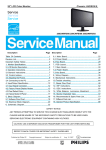
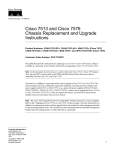
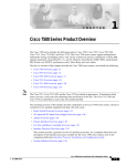
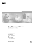
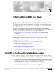
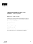
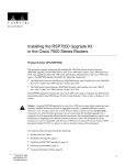
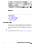
Upgrading the 1200-Watt, AC-Input
Power Supplies in the Cisco 7513
This document contains instructions for upgrading your existing Cisco 7513, 1200-watt (W), alternating
current (AC)–input power supplies, with new AC-input power supplies. (See .) A single power supply is
standard equipment for the Cisco 7513. A second, identical power supply, when installed, provides
redundant power. In systems with redundant power, the power supplies are load-sharing and fully
hot-swappable; you can remove and replace one supply, while the remaining supply immediately ramps
up to full power to maintain uninterrupted system operation.
Caution
The new and older power supplies must not be used simultaneously in the Cisco 7513. The redundant
power, load-sharing feature of the Cisco 7513 requires identical power supplies in each of the two power
supply bays. While no physical damage will occur if two different supplies are installed into a Cisco
7513, there is the possibility of erratic system behavior and error messages.
Note
If your Cisco 7513 contains older AC-input power supplies, Part Number 34-0049-01, or later, use this
document to replace them with new power supplies carrying Part Number 34-0667-01 or later. If you have a
Cisco 7513 with one or two of the older AC-input power supplies, you must replace both of them with the
new AC-input power supplies. All Cisco 7513 chassis must have the new AC-input power supplies installed
in them.
The sections in this document include the following:
•
Determining the Power Supply Model, page 2
•
Product Overview, page 3
•
Installation Safety, ESD Precautions, and Tools Required, page 12
•
Replacing Older AC-Input Power Supplies, page 14
•
Checking the New Power Supply Installation, page 18
•
Related Documentation, page 20
•
Obtaining Documentation, page 20
•
Documentation Feedback, page 21
Corporate Headquarters:
Cisco Systems, Inc., 170 West Tasman Drive, San Jose, CA 95134-1706 USA
Copyright © 2004 Cisco Systems, Inc. All rights reserved.
Determining the Power Supply Model
•
Obtaining Technical Assistance, page 21
•
Obtaining Additional Publications and Information, page 22
Determining the Power Supply Model
The Cisco 7513, AC-input power supplies carry one of the following part numbers:
•
The older AC-input power supply is Part Number 34-0049-01, or later, and shipped in new Cisco
7513 chassis and as spares, before November 14, 1995.
•
The new AC-input power supply is Part Number 34-0667-01, or later, and started shipping in Cisco
7513 chassis as of November 14, 1995.
Figure 1 shows the label attached to the right side of the new AC-input power supplies.
If you are unable to determine if your AC-input power supplies need to be upgraded, based on the
cosmetic differences shown in and , use this label to verify whether or not the AC-input power supply
in your chassis needs to be upgraded.
If the part number on your AC-input power supplies is anything other than 34-0667-01, or later, upgrade
to the new AC-input power supplies.
Figure 1
Label on the New AC-Input Power Supply (Right Side View)
CISCO P/N: 34-0667-01
CISCO REV NO: 01
EC LEVEL JS0324
AGENCY TYPE PS028
DATE CODE 9542
H5269
P/N 004264C
Upgrading the 1200-Watt, AC-Input Power Supplies in the Cisco 7513
2
OL-6324-01
Product Overview
Product Overview
The AC-input power supply is optional equipment in the Cisco 7513. Power supplies reside in power
supply bays in the rear of the router chassis. shows the Cisco 7513 with the older power supplies
installed (Part Number 34-0049-01 or later).
Figure 2
Cisco 7513 (Rear-Panel View with the Older Power Supplies)
Blower module
Cable-management
bracket
NO
RM
AL
EN
AB
LE
EJE
CT
SLO SLO
T0 T1
SLA MAS
VE TE
R
Card cage and
processor modules
SLA
VE
/M
AS
TE
R
CP
U
HA
LT
RE
SE
EN
T
AB
LE
AU
X.
ROUTE SWITCH PROCESSOR 2
CO
NS
OLE
Air intake vent
FAN OUTPUT
OK
AC
FAN OUTPUT
OK
OK
FAIL
FAIL
POWER
A
POWER
I
I
0
0
B
H3087
Power supplies
Chassis grounding
receptacle (2)
AC
OK
Figure 3 shows the Cisco 7513 with the new power supplies installed (Part Number 34-0667-01 or later).
Upgrading the 1200-Watt, AC-Input Power Supplies in the Cisco 7513
OL-6324-01
3
Product Overview
Figure 3
Cisco 7513 (Rear-Panel View with the New Power Supplies)
Blower module
Cable-management
bracket
NO
RM
AL
EN
AB
LE
EJE
CT
SLO SLO
T0 T1
SLA MAS
VE TE
R
Card cage and
processor modules
SLA
VE
/M
AS
TE
R
CP
U
HA
LT
RE
SE
EN
T
AB
LE
AU
X.
ROUTE SWITCH PROCESSOR 2
CO
NS
OLE
Air intake vent
AC
OK
FAN
OK
OUTPUT
FAIL
AC
OK
OUTPUT
FAIL
POWER
A
POWER
B
Chassis grounding
receptacles
Caution
H5268
Power supplies
FAN
OK
I
I
0
0
To prevent problems with the Cisco 7513, do not mix DC-input and AC-input power supplies in the same
chassis. Your Cisco 7513 must have either DC-input or AC-input power supplies. Do not mix new and
older AC-input power supplies in the same chassis.
The power A bay contains the first (or standard) power supply, and the power B bay contains the second
(optional) supply, in systems with redundant power.
Upgrading the 1200-Watt, AC-Input Power Supplies in the Cisco 7513
4
OL-6324-01
Product Overview
Power Supply Specifications
Table 1 lists the AC-input power supply specifications.
The specifications listed in Table 1 apply to the new and older AC-input power supplie
Table 1
Cisco 7513 AC-Input Power Supply Specifications
Specification
Rating
AC-input voltage
100 to 240 VAC1, 20 amps maximum
Frequency
50 to 60 Hz
Internal DC voltages supplied and steady-state
maximum current ratings
+5.2 VAC @ 200A
+12 VAC @ 35A
–12 VAC @ 3A
+24 VAC @ 8A
Input power requirement
1600W
Power output
1200W with a maximum configuration and one or
two AC-input power supplies
Heat dissipation
5465 Btu/hr
Weight
25 pounds (11.34 kilograms)
Cable supplied
12 American Wire Gauge (AWG), 20-amp2
1. VAC = volts direct current.
2. The Cisco 7513 requires a minimum of 20-amp service, with a 20-amp receptacle at the power source. The power cable
supplied with the Cisco 7513 uses a 20-amp male plug.
Dual power supplies are automatically load-sharing and redundant, which means that you can install or
replace a second power supply on line. During normal operation, dual supplies provide system power
simultaneously (load share). When you remove one supply, the remaining supply immediately ramps up
to provide full power and maintain uninterrupted power to the system. Whenever possible, connect each
power supply to a separate AC source.
Caution
The new and older power supplies must not be used simultaneously in the Cisco 7513. The redundant
power, load-sharing feature of the Cisco 7513 requires identical power supplies in each of the two power
supply bays. While no physical damage will occur if the two different supplies are installed into a Cisco
7513, there is the possibility of erratic system behavior and error messages.
The AC-input power supply uses a power factor corrector (PFC) that automatically adjusts for the input
voltage being supplied. The AC-input voltage range is 100 to 240 VAC. The power supplies are
self-monitoring. Each supply monitors its own temperature and internal voltages. An internal fan in each
power supply draws cooling air from the rear of the chassis, through the power supply, and out the front
of the chassis. The power supply airflow is separate from that of the rest of the chassis.
The Cisco 7513 requires a minimum of 20-amp service, with a 20-amp receptacle at the power source.
The power cable supplied with the Cisco 7513 uses a 20-amp male plug. shows the cable connector plug
and the 20-amp receptacle required to connect the 20-amp cable to your AC source.
Note
Wiring codes prevent this type of power cable from being used with the power strips in equipment racks.
Upgrading the 1200-Watt, AC-Input Power Supplies in the Cisco 7513
OL-6324-01
5
Product Overview
Figure 4
H3164
20-Amp AC Power Cable Connector and Plug, and 20-Amp Receptacle
IEC 320 20-amp connector
(to the AC power supply)
20-amp plug
20-amp receptacle
Power Supply LED Indications
On the Cisco 7513 chassis front panel, the power A and power B LEDs go on when the power supply in
the corresponding bay is installed and supplying power to the system. Both the power LEDs should be
on in systems with redundant power.
The power supply LEDs include the AC OK LED, the fan OK LED, and the output fail LED. (See
Figure 5 for an illustration of the new AC-input power supply’s LEDs.)
The AC OK LED is on when the input power is applied. The fan OK LED is normally on; however, it is
off if the power supply fan fails. The output fail LED is normally off, but flashes at power on for a lamp
test.
Figure 5
AC
OK
AC-Input Power Supply LEDs, New Power Supply
FAN
OK
OUTPUT
FAIL
AC
OK
LEDs
FAN
OK
OUTPUT
FAIL
AC power
receptacle
Power supply
front panel
I
0
H5264
Power
switch
Captive
installation
screw
The output fail LED lights for either of the following reasons:
•
Power supply DC-output failure, which could be caused by overload by the system or an actual
failure in the AC-input power.
•
Power shutdown, initiated by the power supply because it detected an out-of-tolerance voltage
condition in the power supply
Upgrading the 1200-Watt, AC-Input Power Supplies in the Cisco 7513
6
OL-6324-01
Product Overview
In systems with a single power supply, and in systems with redundant power when both power supplies
are shutting down, the output fail LED lights momentarily as the system ramps down, but goes out when
the power supply has completely shut down.
The power supplies feature the following three safety interlock features:
An on/off switch with a locking mechanism on each power supply prevents the power supply from
being removed from the chassis when the power supply switch is in the ON (|) position. When the
switch is ON, a metal tab extends into a slot in the chassis. When the switch is OFF (O), the tab is
raised and clears the slot.
•
shows the locking mechanism on the older AC-input power supply. shows the locking mechanism on
the new AC-input power supply.
Figure 6
On/off Switch Locking Mechanism on the Older AC-Input Power Supply
I
H3031
0
Power
switch
Figure 7
Locking device
On/off Switch Locking Mechanism on the New AC-Input Power Supply
I
H5266
0
Power
switch
•
Locking device
A captive installation screw at the bottom of the power supply front panel provides electrical
grounding and prevents the power supply from vibrating or sliding out of the bay and dislodging
from the power connectors in the backplane. (See Figure 5.)
Upgrading the 1200-Watt, AC-Input Power Supplies in the Cisco 7513
OL-6324-01
7
Product Overview
•
A spring clip on the AC receptacle supplies strain relief and prevents the power supply power cable
from being pulled out accidentally.
Environmental Monitoring and Reporting Functions
The environmental monitoring and reporting functions, controlled by the chassis interface board, enable
you to maintain normal system operation by identifying and resolving adverse conditions prior to loss
of operation. The environmental monitoring functions constantly monitor the internal chassis air
temperature and DC supply voltages and currents. Each power supply monitors its own voltage and
temperature and shuts itself down if it detects a critical condition within the power supply. If conditions
reach shutdown thresholds, the system shuts down to avoid equipment damage from excessive heat. The
reporting functions periodically log the values of measured parameters so that you can retrieve them for
analysis later, and the reporting functions display warnings on the console if any of the monitored
parameters exceed defined thresholds.
In addition to monitoring internal temperature and voltage levels, the system also monitors the blower.
If the blower fails, the system displays a warning message on the console. If the blower is still not
operating properly after two minutes, the system shuts down to protect the internal components against
damage from excessive heat.
Environmental Monitoring
Three sensors on the Route Switch Processor (RSP2) monitor the temperature of the cooling air that
flows through the processor slots: inlet, hotpoint, and exhaust. The sensors are located at the bottom,
center, and top of the RSP2, when facing the interface processor end of the chassis and viewing the RSP2
as it is installed.
The power supply uses the Normal, Critical, and Warning levels to monitor DC voltages. Table 2 lists
temperature thresholds for the three processor-monitored levels. Table 3 lists the DC power thresholds
for the Normal and Critical (power-supply-monitored) levels.
•
Normal—All monitored parameters are within normal tolerances. The system blower operates at
55 percent of its maximum speed if the internal air temperature does not exceed this level.
•
Warning (low and high)—The system is approaching an out-of-tolerance condition. The system will
continue to operate, but operator monitoring or action is recommended to bring the system back to
a normal state. If the internal air temperature the normal range, the blower speed will increase
linearly from 55 percent of maximum speed until it reaches 100 percent speed at 33 C (91 F).
•
Critical (low and high)—An out-of-tolerance temperature or voltage condition exists. The system
may not continue operation. If a voltage measurement reaches this level, the power supply can shut
down the system. If the blower fails, the system will display a warning message and shut down in
two minutes. Immediate operator action is required.
•
Processor shutdown—The chassis interface has detected a temperature or blower-failure condition
that could result in physical damage to system components and has disabled DC power to all
interface processors (in slots 0 through 5 and 8 through 12). DC power to the RSP2, chassis
interface, and blower stays on, but no RSP2-related processing takes place. Immediate operator
action is required. DC power remains off until the inside temperature of the chassis reaches 40 C
(104 F), at which point the system will restart up to 15 times (if required). If the source of the
shutdown has not been corrected, the system will execute a hard shutdown. Before any shutdown,
the system logs the status of monitored parameters in NVRAM so that you can retrieve it later to
help determine the cause of the problem.
Upgrading the 1200-Watt, AC-Input Power Supplies in the Cisco 7513
8
OL-6324-01
Product Overview
•
Power supply shutdown—An out-of-tolerance voltage, current, or temperature condition was
detected within the power supply and it was shut down (or a shutdown is imminent). All DC power
remains disabled until the operator toggles the power switch and corrects the problem that caused
the shutdown (if any). This condition typically occurs because of one of the following reasons:
– Loss of AC input power (the power source failed).
– Power supply detected an overvoltage, overcurrent, AC or DC undervoltage, or overtemperature
condition within the power supply. This includes operator shutdown by turning off the system
power switch, which the power supply interprets as an undervoltage condition.
– The chassis interface detected an overtemperature condition within the system.
•
Blower failure—The blower impeller has stopped turning. A warning message is displayed on the
console, and the system will continue operating until it shuts itself down due to overheating.
Table 2
Typical Processor-Monitored Temperature Thresholds
Parameter
Normal
High Warning
High Critical
Shutdown
Inlet
10–40 C
44 C
50 C
–
Hotpoint
10–40 C
54 C
60 C
–
Exhaust
10–40 C
–
–
–
Processors
–
–
–
70 C
Power supply
–
–
–
75 C
Restart
40 C
–
–
–
Table 3
Typical Power Supply-Monitored DC-Voltage Thresholds
Parameter
Normal
Low Critical Low Warning
High Warning
High Critical
+5V
4.74 to 5.26
4.49
4.74
5.25
5.52
+12V
10.20 to 13.8
10.76
11.37
12.64
13.24
–12V
–10.20 to
–13.80
–10.15
–10.76
–13.25
–13.86
+24V
20.00 to 28.00
19.06
21.51
28.87
26.51
If the air temperature exceeds a defined threshold, the system processor displays warning messages on
the console terminal and, if the temperature exceeds the shutdown threshold, it shuts down the system.
The system stores the present parameter measurements for both temperature and DC voltage in
NVRAM, so that you can retrieve it later as a report of the last shutdown parameters.
The power supplies monitor internal power supply temperature and voltages. A power supply is either
within tolerance (Normal) or out of tolerance (Critical or Warning levels), as shown in Table 3. If an
internal power supply temperature or voltage reaches a critical level, the power supply shuts down
without any interaction with the system processor.
If the system detects that AC or DC input power is dropping, but it is able to recover before the power
supply shuts down, it logs the event as an intermittent power failure. The reporting functions display the
cumulative number of intermittent power failures logged since the last power up.
Upgrading the 1200-Watt, AC-Input Power Supplies in the Cisco 7513
OL-6324-01
9
Product Overview
Environmental Reports
The system displays warning messages on the console if chassis interface-monitored parameters exceed
a desired threshold or if a blower failure occurs. You can also retrieve and display environmental status
reports with the show environment, show environment all, show environment last and show
environment table commands. Parameters are measured and reporting functions are updated every 60
seconds. A brief description of each of these commands follows.
Caution
To prevent overheating the chassis, ensure that your system is drawing cool inlet air. Overtemperature
conditions can occur if the system is drawing in the exhaust air of other equipment. When viewing the
chassis from the interface processor end, the airflow intake vent is on the front of the chassis (below the
card cage), and the exhaust vent in on the front of the chassis (behind the lower front panel). Ensure
adequate clearance around the sides of the chassis so that cooling air can flow through the chassis interior
unimpeded. Obstructing or blocking the chassis sides will restrict the airflow and can cause the internal
chassis temperature to exceed acceptable limits.
The show environment command display reports the current environmental status of the system. The
report displays parameters that are out of the normal values. No parameters are displayed if the system
status is normal. The example that follows shows the display for a system in which all monitored
parameters are within Normal range. Following is sample output of the show env command:
Router# show env
All measured values are normal
If the environmental status is not normal, the system reports the worst-case status level in the last line
of the display.
The show environment last command retrieves and displays the NVRAM log showing the reason for
the last shutdown (if the shutdown was related to voltage or temperature) and the environmental status
at that time. Air temperature is measured and displayed; the DC voltages supplied by the power supply
are also displayed. Following is sample output of the show env last command:
Router# show env last
RSP(6) Inlet
RSP(6) Hotpoint
RSP(6) Exhaust
+12 Voltage
+5 Voltage
-12 Voltage
+24 Voltage
previously
previously
previously
previously
previously
previously
previously
measured
measured
measured
measured
measured
measured
measured
at
at
at
at
at
at
at
27C/80F
38C/100F
31C/87F
12.17
5.19
-12.17
23.40
Upgrading the 1200-Watt, AC-Input Power Supplies in the Cisco 7513
10
OL-6324-01
Product Overview
The show environment table command displays the temperature and voltage thresholds for each of the
three RSP2 temperature sensors, for each monitored status level: low critical, low warning, high
warning, and high critical, which are the same as those listed in Tables 2 and 3. The slots in which the
RSP2 can be installed are indicated in parentheses (6 and 7). Also listed are the shutdown thresholds for
the processor boards and power supplies. Following is sample output of the show env table command:
Router# show env table
Sample Point
LowCritical
RSP(6) Inlet
RSP(6) Hotpoint
RSP(6) Exhaust
RSP(7) Inlet
RSP(7) Hotpoint
RSP(7) Exhaust
+12 Voltage
10.76
+5 Voltage
4.49
-12 Voltage
-10.15
+24 Voltage
19.06
Shutdown boards at
Shutdown power supplies at
Note
LowWarning
11.37
4.74
-10.76
21.51
101C/213F
101C/213F
HighWarning
HighCritical
44C/111F
54C/129F
50C/122F
60C/140F
44C/111F
54C/129F
50C/122F
60C/140F
12.64
5.25
-13.25
26.51
13.24
5.52
-13.86
28.87
Temperature ranges and values are subject to change.
The show environment all command displays an extended report that includes the arbiter type,
backplane type, power supply type (AC or DC), wattage and status, the number and type of intermittent
power failures (if any) since the system was last powered on, and the currently measured values at the
RSP2 temperature sensors and the DC-input lines. The show environment all command also displays a
report showing which slots in the Cisco 7513 are occupied (indicated by an X) and which are empty.
Note
The current monitor circuits of the 7513 power supply are only accurate at high power levels. They are
there to prevent over-configuration and serve no purpose at low power levels. If the system is not
operating above 70% power, the measurement results are not accurate. Above 70%, the measurements
have the degree of accuracy needed to prevent the insertion of too many line cards into the system.
Active fault conditions are indicated when the blower or power supply has failed or is not present (as
“Blower #3” indicates in the following example). The system expects to see three blowers or fans in the
Cisco 7513: the main system blower, and one fan in each power supply. The system blower is designated
#1, the power supply fan in power bay A is #2, and the power supply fan in power bay B is #3. The active
fault condition in the following example shows that there is no power supply installed in power bay B
because the display indicates that power supply #2 (in power bay B) is removed. System blower speed
is displayed as a percentage of maximum.
There are four active trip points: restart OK, temperature warning, board shutdown, and power supply
shutdown. (There are no active trip points shown in the following example.) The soft shutdowns refer to
the number of times the system will reset itself before it executes a complete chassis (or hard) shutdown.
The current temperature measurements at the three RSP2 sensors are displayed as inlet, hotpoint, and
exhaust. The shutdown temperature source is the hotpoint sensor, which is located toward the center of
the RSP2. System voltage measurements are also displayed, followed by the system current
measurements and power supply wattage calculation. Following is sample output of the show env all
command:
Router# show env all
Arbiter type 1, backplane type 7513 (id 2)
Upgrading the 1200-Watt, AC-Input Power Supplies in the Cisco 7513
OL-6324-01
11
Installation Safety, ESD Precautions, and Tools Required
Power supply #1 is 1200W AC (id 1), power supply #2 is removed (id 7)
Active fault conditions: Blower #3
Fan speed is 50%
Active trip points: none
15 of 15 soft shutdowns remaining before hard shutdown
1
0123456789012
Dbus slots: XX XXXX XXXX
RSP(6)
inlet
24C/75F
hotpoint
35C/95F
exhaust
29C/84F
Shutdown temperature source is 'hotpoint' slot6 (requested slot6)
+12V
+5V
-12V
+24V
+2.5
PS1
PS1
PS1
PS1
measured at 12.17
measured at 5.19
measured at -12.26
measured at 24.44
reference is 2.49
+5V Current
measured at 42.35 A (capacity 200 A)
+12V Current
measured at 6.86 A (capacity 35 A)
-12V Current
measured at 0.55 A (capacity 3 A)
output is 296 W
Installation Safety, ESD Precautions, and Tools Required
Before you begin this installation, review the safety guidelines in this section to avoid injuring yourself
or damaging the equipment. This section also provides power requirements to consider if you are adding
a second power supply to your system for redundant power, and lists of the tools and parts you need to
perform this installation.
Safety Guidelines
The following guidelines will help to ensure your safety and protect the equipment. This list is not
inclusive of all potentially hazardous situations, so be alert.
•
Never try to lift the chassis by yourself; two people are required to lift the Cisco 7513.
•
Always disconnect all power cords and interface cables before moving the chassis.
•
Keep tools and chassis components away from walk areas.
•
Do not work alone if potentially hazardous conditions exist.
•
Do not perform any action that creates a potential hazard to people or makes the equipment unsafe.
•
Carefully examine your work area for possible hazards such as moist floors, ungrounded power
extension cables, and missing safety grounds.
Safety with Electricity
You can remove or install a redundant (second) power supply without turning off the other supply.
Before removing a redundant power supply, ensure that the first supply is powered on to ensure
uninterrupted operation.
Follow these basic guidelines when working with any electrical equipment:
Upgrading the 1200-Watt, AC-Input Power Supplies in the Cisco 7513
12
OL-6324-01
Installation Safety, ESD Precautions, and Tools Required
•
Before beginning any procedures requiring access to the chassis interior, locate the emergency
power-off switch for the room in which you are working.
•
Disconnect all power and external cables before moving a chassis.
•
Do not work alone if potentially hazardous conditions exist.
•
Never assume that power is disconnected from a circuit; always check.
•
Do not perform any action that creates a potential hazard to people or makes the equipment unsafe.
•
Carefully examine your work area for possible hazards such as moist floors, ungrounded power
extension cables, and missing safety grounds.
In addition, use the guidelines that follow when working with any equipment that is connected to
telephone wiring or other network cabling.
•
Never install telephone wiring during a lightning storm.
•
Never install telephone jacks in wet locations unless the jack is specifically designed for wet
locations.
•
Never touch uninsulated telephone wires or terminals unless the telephone line is disconnected at
the network interface.
•
Use caution when installing or modifying telephone lines.
Preventing Electrostatic Discharge Damage
Electrostatic discharge (ESD) damage, which can occur when electronic boards or components are
handled improperly, can result in complete or intermittent failures.
Following are guidelines for preventing ESD damage:
Warning
•
Always use an ESD-preventive wrist strap or ankle strap and ensure that it makes good skin contact.
•
When removing or installing a power supply, connect the equipment end of a ground strap to the
chassis ground screw on the interface processor end of the chassis, or to an unpainted surface inside
the noninterface processor end of the chassis, such as the chassis frame.
•
If you are returning a replaced part to the factory, immediately place it in a static shielding bag to
avoid ESD damage to the board.
•
The wrist strap only protects the board from ESD voltages on the body; ESD voltages on clothing
can still cause damage.
For safety, periodically check the resistance value of the antistatic strap. The measurement should
be between 1 and 10 megohms.
Tools and Parts Required
You need the following tools to install or replace a power supply:
•
A 1/4-inch flat-blade and Number 2 Phillips screwdriver.
•
Small, wire cutter.
•
If the chassis is mounted in an equipment rack, and cables from other equipment fall in front of the
power supply bays, you will need cable ties to temporarily anchor the cables out of the way.
Upgrading the 1200-Watt, AC-Input Power Supplies in the Cisco 7513
OL-6324-01
13
Replacing Older AC-Input Power Supplies
Note
•
If access to the power supply bays is partially blocked by a power strip or other permanent rack
fixture, you will need a 1/4-inch flat-blade screwdriver to temporarily detach the ears from the
equipment rack mounting strips.
•
ESD-preventive wrist strap.
•
At least one new AC-input power supply, Part Number 34-0667-01. (Replaces power supply Part
Number 34-0049-01.)
If you have a Cisco 7513 with one or two of the older AC-input power supplies, you must replace both
with the new AC-input power supplies. All Cisco 7513 chassis must have the new power supplies
installed in them.
•
Note
AC-input power cords from your currently installed power supplies.
The new AC-input power supplies, which are included with this upgrade, do not ship with new AC-input
power cords.
Before beginning the power supply installation, check the installation screws on all power supplies and
check the area around the power supply bays to determine which tools you will need. The new power
supply and the power cable, that you supply, are the only parts you need to complete this installation.
If you remove a power supply and leave the bay empty, install a power supply blank in the empty power
supply bay. (See .) Chassis shipped with a single power supply include a power supply blank installed
in the empty power supply bay.
Circuit Protection Requirements
Based on the NFPA 70 National Electrical Code, you should use a 35A overcurrent protector to meet the
requirement for the overcurrent protector size of 125 percent of the load current, which is approximately
27A. An overcurrent protector rated for 30A can be used only if it has been listed by the safety agency
for operation at 100 percent of its rating.
Replacing Older AC-Input Power Supplies
The following procedures describe removing the older power supplies from your Cisco 7513 (Part
Number 34-0049-01 or later), and installing new power supplies (Part Number 34-0667-01 or later).
All power supplies rest on the floor of the chassis under the card cage.
Note
Warning
If cables from other equipment are in front of the bay, move them aside and temporarily secure them
with cable ties.
Although it is not necessary to turn OFF both power supplies to remove one of two power supplies,
you must turn OFF the power to the power supply you plan to remove. When the power is on with one
of two power supplies removed, high current is exposed on the power connector inside the chassis.
If you have only one power supply, you must turn OFF the power to this power supply.
Upgrading the 1200-Watt, AC-Input Power Supplies in the Cisco 7513
14
OL-6324-01
Removing Older Power Supplies
Removing Older Power Supplies
Follow these steps to remove an older power supply (Part Number 34-0049-01 or later):
H3117
Step 1
Turn OFF (O) the system power switch on the power supply you plan to remove.
Step 2
If possible, turn OFF the circuit breaker to which the system is connected and tape the breaker switch in
the OFF position.
Warning
This unit might have more than one power cord. To reduce the risk of electric shock, disconnect the
two power supply cords before servicing the unit. (To see translated versions of this warning, refer
to page 19.)
Step 3
Disconnect the power cable from the power receptacle of the power supply to be replaced.
Step 4
Use the large slotted screwdriver to loosen the captive screw that secures the power supply to the chassis
frame. (See .) Only loosen the captive screw of the power supply you are removing.
Figure 8
Removing an Older Power Supply
AC
FAN OUTPUT
OK
OK
H3029
FAIL
I
0
Step 5
Grasp the power supply handle and pull the power supply about halfway out of the bay. Then with your
other hand under the power supply, pull it completely out of the bay. (See .)
Upgrading the 1200-Watt, AC-Input Power Supplies in the Cisco 7513
OL-6324-01
15
Removing Older Power Supplies
Figure 9
Supporting the Older Power Supply
AC
FAN OUTPUT
OK
OK
H3029
FAIL
I
0
Step 6
Caution
If you have a second power supply, repeat steps 1 through 5 to remove it.
To maintain agency compliance requirements and meet EMI emissions standards in a Cisco 7513 chassis
with a single power supply, the power supply blank must remain in the power supply bay adjacent to the
power supply. (See .) Do not remove this blank from the chassis unless you do so to install a redundant
power supply. To prevent system problems, do not mix AC-input and DC-input power supplies in the
same chassis.
Power Supply Blank
H3539
Figure 10
Captive screw
This completes the removal procedure for the older power supplies.
Installing New Power Supplies
Follow these steps to install a new power supply (Part Number 34-0667-01 or later):
Step 1
Hold the supply as shown in and slide it into the power supply bay. Push the supply all the way into the
chassis until the sides are flush against the chassis frame. To prevent damaging the backplane connector,
do not jam the power supply into the bay.
Upgrading the 1200-Watt, AC-Input Power Supplies in the Cisco 7513
16
OL-6324-01
Removing Older Power Supplies
Figure 11
FAN
OK
OUTPUT
FAIL
H5267
AC
OK
Supporting the New Power Suppl
I
0
Step 2
Use the large slotted screwdriver to tighten the captive screw that secures the power supply to the chassis
frame. (See .)
Figure 12
Location of Captive Installation Screws on the New Power Supply
AC
OK
FAN
OK
OUTPUT
FAIL
AC
OK
FAN
OK
OUTPUT
FAIL
POWER
B
I
I
0
H5265
0
Captive screws
Step 3
Reconnect the power cable to the power receptacle on the power supply.
Warning
This unit might have more than one power cord. To reduce the risk of electric shock, disconnect the
two power supply cords before servicing the unit. (To see translated versions of this warning, refer
to page 19.)
Note
The new AC-input power supplies, which are included with this upgrade, do not ship with new AC-input
power cords.
Step 4
After the AC power cable is reconnected, reconnect the power cable at the power source but do not turn
ON power to the new power supply.
Step 5
If you are replacing both power supplies, repeat Steps 1 through 3 for the second power supply.
This completes the installation procedure for the new power supplies.
Proceed to the following section “Checking the New Power Supply Installation” to apply power and
check the installation.
Upgrading the 1200-Watt, AC-Input Power Supplies in the Cisco 7513
OL-6324-01
17
Checking the New Power Supply Installation
Checking the New Power Supply Installation
To complete the installation, turn each power supply on and observe its LEDs to verify that it is operating
properly.
Step 1
Review the descriptions of the power supply LEDs on page 6.
Step 2
Check the following components to make sure they are secure:
•
Each power supply is inserted all the way into its bay, and the captive installation screw is tightened.
•
All power supply cables are attached to the power receptacles and secured with their spring clips.
•
At the AC power-source end of the power cable, the cables are securely attached to the AC power,
the source power is within the range indicated on the power supply.
•
When two supplies are present, the second cable is connected to a separate AC power source if
possible.
Step 3
Remove the tape (that you applied earlier) from the circuit breaker switch handle and restore power by
moving the circuit breaker handle to the ON position.
Step 4
Turn the power supply ON (|) by turning the switch clockwise one-quarter turn. The AC OK LED and
the fan OK LED will go on and stay on. No other LEDs should go on.
If the power supply switch resists, it is probably not fully inserted into the bay. Turn the power switch
fully counterclockwise to OFF (O), pull the power supply out of the bay about two inches, then push the
power supply firmly back into the slot. Do not slam the supply into the slot—doing so can damage the
connectors on the supply and the backplane. Tighten the captive installation screw before proceeding.
Step 5
Verify that the output fail LED stays off.
•
If the output fail LED goes on, move the power supply to the other bay if possible and turn the power
switch ON (|). If the LEDs go on properly when the supply is installed in the other bay, suspect a
faulty backplane power connector.
•
If the output fail LED goes on when the power supply is installed in the other bay, suspect a power
supply failure or an adverse environmental condition (the power supply has detected an overvoltage
or overtemperature condition and has shut down).
•
If two power supplies are installed, and the output fail LED goes on only on one power supply,
assume that the power supply or AC source (for that supply) is faulty.
•
If the output fail LED lights on two supplies that are connected to the same AC source, suspect that
the AC source is faulty, or that an overvoltage or overtemperature condition is causing the power
supplies to shut down.
•
If the output fail LED lights on two supplies that are connected to separate AC sources, assume that
an overvoltage or overtemperature condition is causing the power supplies to shut down.
If the power supply fails to operate properly after several attempts to initialize it, contact a service
representative for assistance. If the power supply fails (and you need to order a replacement) and you
did not record the type of power supply in your chassis, you will have to check the chassis in order to
make this determination.
Timesaver
The system can identify which type of power supplies are in your chassis: DC-input or AC-input. As a
general precaution, use the show environment all command and note the type of power supply indicated
in each of your chassis (indicated as “1200W AC”). Record and save this information in a secure place.
Upgrading the 1200-Watt, AC-Input Power Supplies in the Cisco 7513
18
OL-6324-01
Checking the New Power Supply Installation
This completes the power supply upgrade.
Refer to the Cisco 7513 Hardware Installation and Maintenance publication for installation
troubleshooting procedures, and to the appropriate software configuration publication for descriptions
and examples of software configuration features and commands.
Power Cord Warning
Warning
This unit might have more than one power cord. To reduce the risk of electric shock, disconnect the
two power supply cords before servicing the unit.
Waarschuwing
Dit toestel kan meer dan één netsnoer hebben. Om het risico van een elektrische schok te
verminderen, dient u de stekkers van de twee netsnoeren uit het stopcontact te halen voordat u het
toestel een servicebeurt geeft.
Varoitus
Tässä laitteessa saattaa olla useampi kuin yksi virtajohto. Irrota molemmat virtalähteestä tulevat
johtimet ennen laitteen huoltamista, jotta vältät sähköiskun vaaran.
Attention
Il est possible que cette unité soit munie de plusieurs cordons d'alimentation. Pour éviter les
risques d'électrocution, débrancher les deux cordons d'alimentation avant de réparer l'unité.
Warnung
Diese Einheit hat möglicherweise mehr als ein Netzkabel. Zur Verringerung der Stromschlaggefahr
trennen Sie beide Netzgerätekabel ab, bevor Sie die Einheit warten.
Avvertenza
Advarsel
Aviso
¡Advertencia!
Varning!
Questa unità potrebbe essere dotata di più di un cavo di alimentazione. Per ridurre il rischio di
scossa elettrica, scollegare i due cavi di alimentazione prima di procedere alla manutenzione
dell’unità.
Denne enheten kan være utstyrt med mer enn én strømledning. Koble fra de to strømledningene før
det utføres reparasjonsarbeid på enheten for å redusere faren for elektriske støt.
Esta unidade poderá ter mais do que um cabo de alimentação. Para reduzir o risco de choque
eléctrico, desligue os dois cabos de alimentação antes de efectuar reparações na unidade.
Puede ser que este equipo posea más de un cable de alimentación. Para reducir el riesgo de
descarga eléctrica, desenchufar los dos cables antes de proceder al mantenimiento de la unidad.
Denna enhet kan vara försedd med mer än en nätsladd. För att minska risken för elektriska stötar
skall båda nätsladdarna dras ur innan du utför underhållsarbete på enheten.
Upgrading the 1200-Watt, AC-Input Power Supplies in the Cisco 7513
OL-6324-01
19
Related Documentation
Related Documentation
See the following for a listing of additional documentation for the Cisco 7500 Series routers:
•
Cisco 7500 Series Documentation Roadmap
•
Cisco 7500 Series Routers Port Adapter Documentation Roadmap
•
Cisco 7500 Series Routers Processor Documentation Roadmap
•
Cisco 7500 Series Routers Troubleshooting Roadmap
Obtaining Documentation
Cisco documentation and additional literature are available on Cisco.com. Cisco also provides several
ways to obtain technical assistance and other technical resources. These sections explain how to obtain
technical information from Cisco Systems.
Cisco.com
You can access the most current Cisco documentation at this URL:
http://www.cisco.com/univercd/home/home.htm
You can access the Cisco website at this URL:
http://www.cisco.com
You can access international Cisco websites at this URL:
http://www.cisco.com/public/countries_languages.shtml
Ordering Documentation
You can find instructions for ordering documentation at this URL:
http://www.cisco.com/univercd/cc/td/doc/es_inpck/pdi.htm
Upgrading the 1200-Watt, AC-Input Power Supplies in the Cisco 7513
20
OL-6324-01
Documentation Feedback
You can order Cisco documentation in these ways:
•
Registered Cisco.com users (Cisco direct customers) can order Cisco product documentation from
the Ordering tool:
http://www.cisco.com/en/US/partner/ordering/index.shtml
•
Nonregistered Cisco.com users can order documentation through a local account representative by
calling Cisco Systems Corporate Headquarters (California, USA) at 408 526-7208 or, elsewhere in
North America, by calling 800 553-NETS (6387).
Documentation Feedback
You can send comments about technical documentation to [email protected].
You can submit comments by using the response card (if present) behind the front cover of your
document or by writing to the following address:
Cisco Systems
Attn: Customer Document Ordering
170 West Tasman Drive
San Jose, CA 95134-9883
We appreciate your comments.
Obtaining Technical Assistance
For all customers, partners, resellers, and distributors who hold valid Cisco service contracts, Cisco
Technical Support provides 24-hour-a-day, award-winning technical assistance. The Cisco Technical
Support Website on Cisco.com features extensive online support resources. In addition, Cisco Technical
Assistance Center (TAC) engineers provide telephone support. If you do not hold a valid Cisco service
contract, contact your reseller.
Cisco Technical Support Website
The Cisco Technical Support Website provides online documents and tools for troubleshooting and
resolving technical issues with Cisco products and technologies. The website is available 24 hours a day,
365 days a year at this URL:
http://www.cisco.com/techsupport
Access to all tools on the Cisco Technical Support Website requires a Cisco.com user ID and password.
If you have a valid service contract but do not have a user ID or password, you can register at this URL:
http://tools.cisco.com/RPF/register/register.do
Submitting a Service Request
Using the online TAC Service Request Tool is the fastest way to open S3 and S4 service requests. (S3
and S4 service requests are those in which your network is minimally impaired or for which you require
product information.) After you describe your situation, the TAC Service Request Tool automatically
Upgrading the 1200-Watt, AC-Input Power Supplies in the Cisco 7513
OL-6324-01
21
Obtaining Additional Publications and Information
provides recommended solutions. If your issue is not resolved using the recommended resources, your
service request will be assigned to a Cisco TAC engineer. The TAC Service Request Tool is located at
this URL:
http://www.cisco.com/techsupport/servicerequest
For S1 or S2 service requests or if you do not have Internet access, contact the Cisco TAC by telephone.
(S1 or S2 service requests are those in which your production network is down or severely degraded.)
Cisco TAC engineers are assigned immediately to S1 and S2 service requests to help keep your business
operations running smoothly.
To open a service request by telephone, use one of the following numbers:
Asia-Pacific: +61 2 8446 7411 (Australia: 1 800 805 227)
EMEA: +32 2 704 55 55
USA: 1 800 553 2447
For a complete list of Cisco TAC contacts, go to this URL:
http://www.cisco.com/techsupport/contacts
Definitions of Service Request Severity
To ensure that all service requests are reported in a standard format, Cisco has established severity
definitions.
Severity 1 (S1)—Your network is “down,” or there is a critical impact to your business operations. You
and Cisco will commit all necessary resources around the clock to resolve the situation.
Severity 2 (S2)—Operation of an existing network is severely degraded, or significant aspects of your
business operation are negatively affected by inadequate performance of Cisco products. You and Cisco
will commit full-time resources during normal business hours to resolve the situation.
Severity 3 (S3)—Operational performance of your network is impaired, but most business operations
remain functional. You and Cisco will commit resources during normal business hours to restore service
to satisfactory levels.
Severity 4 (S4)—You require information or assistance with Cisco product capabilities, installation, or
configuration. There is little or no effect on your business operations.
Obtaining Additional Publications and Information
Information about Cisco products, technologies, and network solutions is available from various online
and printed sources.
•
Cisco Marketplace provides a variety of Cisco books, reference guides, and logo merchandise. Visit
Cisco Marketplace, the company store, at this URL:
http://www.cisco.com/go/marketplace/
•
The Cisco Product Catalog describes the networking products offered by Cisco Systems, as well as
ordering and customer support services. Access the Cisco Product Catalog at this URL:
http://cisco.com/univercd/cc/td/doc/pcat/
Upgrading the 1200-Watt, AC-Input Power Supplies in the Cisco 7513
22
OL-6324-01
Obtaining Additional Publications and Information
•
Cisco Press publishes a wide range of general networking, training and certification titles. Both new
and experienced users will benefit from these publications. For current Cisco Press titles and other
information, go to Cisco Press at this URL:
http://www.ciscopress.com
•
Packet magazine is the Cisco Systems technical user magazine for maximizing Internet and
networking investments. Each quarter, Packet delivers coverage of the latest industry trends,
technology breakthroughs, and Cisco products and solutions, as well as network deployment and
troubleshooting tips, configuration examples, customer case studies, certification and training
information, and links to scores of in-depth online resources. You can access Packet magazine at this
URL:
http://www.cisco.com/packet
•
iQ Magazine is the quarterly publication from Cisco Systems designed to help growing companies
learn how they can use technology to increase revenue, streamline their business, and expand
services. The publication identifies the challenges facing these companies and the technologies to
help solve them, using real-world case studies and business strategies to help readers make sound
technology investment decisions. You can access iQ Magazine at this URL:
http://www.cisco.com/go/iqmagazine
•
Internet Protocol Journal is a quarterly journal published by Cisco Systems for engineering
professionals involved in designing, developing, and operating public and private internets and
intranets. You can access the Internet Protocol Journal at this URL:
http://www.cisco.com/ipj
•
World-class networking training is available from Cisco. You can view current offerings at
this URL:
http://www.cisco.com/en/US/learning/index.html
This document is to be used in conjunction with the documents listed in the “Related Documentation” section on page 20 ..
CCSP, the Cisco Square Bridge logo, Cisco Unity, Follow Me Browsing, FormShare, and StackWise are trademarks of Cisco Systems, Inc.; Changing
the Way We Work, Live, Play, and Learn, and iQuick Study are service marks of Cisco Systems, Inc.; and Aironet, ASIST, BPX, Catalyst, CCDA, CCDP,
CCIE, CCIP, CCNA, CCNP, Cisco, the Cisco Certified Internetwork Expert logo, Cisco IOS, Cisco Press, Cisco Systems, Cisco Systems Capital, the
Cisco Systems logo, Empowering the Internet Generation, Enterprise/Solver, EtherChannel, EtherFast, EtherSwitch, Fast Step, GigaDrive, GigaStack,
HomeLink, Internet Quotient, IOS, IP/TV, iQ Expertise, the iQ logo, iQ Net Readiness Scorecard, LightStream, Linksys, MeetingPlace, MGX, the
Networkers logo, Networking Academy, Network Registrar, Packet, PIX, Post-Routing, Pre-Routing, ProConnect, RateMUX, Registrar, ScriptShare,
SlideCast, SMARTnet, StrataView Plus, SwitchProbe, TeleRouter, The Fastest Way to Increase Your Internet Quotient, TransPath, and VCO are
registered trademarks of Cisco Systems, Inc. and/or its affiliates in the United States and certain other countries.
All other trademarks mentioned in this document or Website are the property of their respective owners. The use of the word partner does not imply a
partnership relationship between Cisco and any other company. (0406R)
Copyright © 2004 Cisco Systems, Inc. All rights reserved.
Printed in the USA on recycled paper containing 10% postconsumer waste.
Upgrading the 1200-Watt, AC-Input Power Supplies in the Cisco 7513
OL-6324-01
23
Obtaining Additional Publications and Information
Upgrading the 1200-Watt, AC-Input Power Supplies in the Cisco 7513
24
OL-6324-01