1
DECserver 900GM and 900GMx
Installation
Part Number: EK–DSRVY–IN. C01
February 1997
This manual describes how to install the
DECserver 900GM and DECserver 900GMx modules.
Revision/Update Information:
This is a revised manual.
Copyright
February 1997
The information in this document is subject to change without notice and should not be construed as a
commitment by Digital Equipment Corporation. Digital Equipment Corporation assumes no responsibility
for any errors that may appear in this document.
Copyright 1997 by Digital Equipment Corporation
All rights reserved. Printed in U.S.A.
The postage-paid Reader’s Comments form at the back of this document requests your evaluation of this
document to assist us in preparing future documentation.
The following are trademarks of Digital Equipment Corporation: DEC, DECconcentrator, DECconnect,
DEChub, DEChub ONE, DECndu, DECndu Plus, Digital, HUBwatch, OpenVMS, ULTRIX, VAX, VMS, and
the DIGITAL logo.
AT&T is a registered trademark and ST is a trademark of American Telephone and Telegraph Company.
MS-DOS is a registered trademark of Microsoft Corporation.
All other trademarks are the property of their respective owners.
FCC NOTICE — Class A Computing Device:
This equipment generates, uses, and may emit radio frequency energy. The equipment has been type
tested and found to comply with the limits for a Class A computing device pursuant to Subpart J of Part 15
of FCC Rules, which are designed to provide reasonable protection against such radio frequency
interference when operated in a commercial environment. Operation of this equipment in a residential area
may cause interference; in which case, measures taken to correct the interference are at the user’s
expense.
VCCI NOTICE — Class 1 Computing Device:
This equipment is in the 1st Class category (information equipment to be used in commercial and/or
industrial areas) and conforms to the standards set by the Voluntary Control Council for Interference by
Data Processing Equipment and Electronic Office Machines aimed at preventing radio interference in
commercial and/or industrial areas. Consequently, when used in a residential area or in an adjacent area
thereto, radio interference may be caused to radios and TV receivers. Read the instructions for correct
handling.
LASER NOTICE – Class 1 Laser Device:
The lasers in this equipment are Class 1 devices, compliant with CDRH Rules 22, CFR Subchapter J, Part
1040.10, at date of manufacture. Class 1 laser devices are not considered to be hazardous.
CE NOTICE – Class A Computing Device:
Warning!
This is a Class A product. In a domestic environment this product may cause radio interference, in which
case the user may be required to take adequate measures.
Achtung!
Dieses ist ein Gerät der Funkstörgrenzwertklasse A. In Wohnbereichen können bei Betrieb dieses
Gerätes Rundfunkstörungen auftreten, in welchen Fällen der Benutzer für entsprechende
Gegenmaßnahmen verantwortlich ist.
Attention!
Ceci est un produit de Classe A. Dans un environment domestique, ce produit risque de créer des
interférences radioélectriques, il appartiendraalors à l’utilisateur de prendre les mesures spécifiques
appropriées.
Contents
Safety . . . . . . . . . . . . . . . . . . . . . . . . . . . . . . . . . . . . . . . . . . . . . . . . . . . . . . . . v
Introduction . . . . . . . . . . . . . . . . . . . . . . . . . . . . . . . . . . . . . . . . . . . . . . . . . . 1
Features . . . . . . . . . . . . . . . . . . . . . . . . . . . . . . . . . . . . . . . . . . . . . . . . . . . 2
Front Panel DECserver 900GM . . . . . . . . . . . . . . . . . . . . . . . . . . . . . . . 3
Front Panel DECserver 900GMx . . . . . . . . . . . . . . . . . . . . . . . . . . . . . . 5
Back Panel . . . . . . . . . . . . . . . . . . . . . . . . . . . . . . . . . . . . . . . . . . . . . . . . . . . 6
Installing the Module . . . . . . . . . . . . . . . . . . . . . . . . . . . . . . . . . . . . . . . . . 7
Installing Flash RAM . . . . . . . . . . . . . . . . . . . . . . . . . . . . . . . . . . . . . . . . . 10
Removing the Module . . . . . . . . . . . . . . . . . . . . . . . . . . . . . . . . . . . . . . . . 11
LED Descriptions . . . . . . . . . . . . . . . . . . . . . . . . . . . . . . . . . . . . . . . . . . . . . 12
Problem Solving Using the LEDs . . . . . . . . . . . . . . . . . . . . . . . . . . . . . 13
Normal Powerup . . . . . . . . . . . . . . . . . . . . . . . . . . . . . . . . . . . . . . . . . . . . 13
Problem Solving . . . . . . . . . . . . . . . . . . . . . . . . . . . . . . . . . . . . . . . . . . . . . 13
Problem Solving Using the Seven Segment Display . . . . . . . . . . 16
Cabling . . . . . . . . . . . . . . . . . . . . . . . . . . . . . . . . . . . . . . . . . . . . . . . . . . . . . . . 17
Connector Pin Assignments . . . . . . . . . . . . . . . . . . . . . . . . . . . . . . . . . 18
Bulk Connector . . . . . . . . . . . . . . . . . . . . . . . . . . . . . . . . . . . . . . . . . . . . .
H8586-AA . . . . . . . . . . . . . . . . . . . . . . . . . . . . . . . . . . . . . . . . . . . . . . . . .
BN41C-03 . . . . . . . . . . . . . . . . . . . . . . . . . . . . . . . . . . . . . . . . . . . . . . . . .
BN41A-03 . . . . . . . . . . . . . . . . . . . . . . . . . . . . . . . . . . . . . . . . . . . . . . . . .
BN41B-03 . . . . . . . . . . . . . . . . . . . . . . . . . . . . . . . . . . . . . . . . . . . . . . . . .
BN41D-03 . . . . . . . . . . . . . . . . . . . . . . . . . . . . . . . . . . . . . . . . . . . . . . . . .
18
20
21
22
25
30
Cable Compatibility . . . . . . . . . . . . . . . . . . . . . . . . . . . . . . . . . . . . . . . . . . . 35
H8587-AA Loopback Connector . . . . . . . . . . . . . . . . . . . . . . . . . . . . . . . . 37
iii
Contents (Cont.)
Product Specifications . . . . . . . . . . . . . . . . . . . . . . . . . . . . . . . . . . . . . . . 38
Associated Documents . . . . . . . . . . . . . . . . . . . . . . . . . . . . . . . . . . . . . . . 40
Tables
1 Module LED States . . . . . . . . . . . . . . . . . . . . . . . . . . . . . . . . . . . . . . . .
2 Problem Solving Using the LEDs . . . . . . . . . . . . . . . . . . . . . . . . . . . . .
3 Seven Segment Display Codes . . . . . . . . . . . . . . . . . . . . . . . . . . . . . . .
4 Maximum Cable Lengths –– DECserver 900GM to Devices . . . . . . .
5 68-pin to Four 25-pin DB Octopus Cable Pinout . . . . . . . . . . . . . . . . .
6 68-pin to Eight 8-pin MP Octopus Pinout . . . . . . . . . . . . . . . . . . . . . . .
7 68-pin to Eight 25-pin DB Octopus Pinout . . . . . . . . . . . . . . . . . . . . . .
8 Cable Connections Compatible with the DECserver 900GM . . . . . . . .
9 Operating Specifications . . . . . . . . . . . . . . . . . . . . . . . . . . . . . . . . . . . .
10 Acoustical Specifications . . . . . . . . . . . . . . . . . . . . . . . . . . . . . . . . . . .
iv
12
14
16
17
23
26
31
35
38
39
Safety
!
Any warning or caution that appears in this manual is defined as follows:
WARNING
Contains information to prevent personal injury.
VORSICHT
Enthält Informationen, die beachtet werden müssen,
um den Benutzer vor Schaden zu bewahren.
DANGER
Signale les informations destinées à prévenir les accidents corporels.
AVISO
Contiene información para evitar daños personales.
v
!
Safety
WARNING
!
(Cont.)
To avoid personal injury or damage to equipment, do not
install the module into a DEChub 900 or DEChub ONE
unless the module is completely assembled, with the enclosure, bezel, and all faceplates in place. [Page 7.]
VORSICHT
Um den Benutzer vor Schaden zu bewahren und eine
Beschädigung des Geräts zu vermeiden, muß das Modul
erst vollständig mit Gehäuse, Blende und Anschlußdose
montiert werden, bevor es in ein System DEChub 900
oder DEChub ONE eingebaut wird.
DANGER
Pour éviter tout risque d’accident corporel ou de dommage àl’équipement, n’installez le module dans un
DEChub 900 ou un DEChub ONE que s’il est complètement monté et que le boîtier,le couvercle et les caches
ont été mis en place.
AVISO
Para evitar daños personales o al equipo, no se debe
instalar el módulo en un DEChub 900 o un DEChub ONE
a menos que el módulo esté completamente ensamblado, con la carcasa, la tapa y las placas de conexión en
sus respectivos lugares.
vi
Introduction
The DECserver 900GM is a network access server that supports up to 16 full modem
control ports, or 32 eight–wire partial modem control ports. The DECserver 900GMx
is identical to the DECserver 900GM, except that it supports up to 8 full modem
control ports, or 16 eight–wire partial modem control ports. The ports may be used to
connect asynchronous devices including terminals, printers, modems, or PCs to an
Ethernet local area network (LAN). Both systems operate in a DEChub 900
Multiswitch or as a standalone access server.
Except where noted, all references to the DECserver 900GM also apply to the
DECserver 900GMx.
NOTE:
In this manual, the term Ethernet is Digital’s term for its product compatibility
with the ISO 8802-3/ANSI/IEEE 802.3 standards and the Ethernet
standards for Carrier Sense Multiple Access with Collision detection
(CSMA/CD) local area networks (LANs).
To give your workgroup LAN media flexibility and connectivity, the module can be
configured into a DEChub 900 MultiSwitch (also referred to in this manual as the
DEChub 900). One or more DECserver 900GM modules can be installed into the
DEChub 900 (a maximum of 8 DECservers can be present; however, to connect to
the network, there must also be at least one repeater or one bridge in the
configuration). The module can also serve as a standalone unit when configured with
a DEChub ONE docking station (see the DEChub ONE installation manual).
When the module is installed into a DEChub 900, the module’s hot-swap capability
allows you to install or remove the module without turning off power to the DEChub
900.
The DECserver 900GM is configured with four 68-pin D-connectors (two for the
DECserver 900GMx), and provides full or limited modem control. Each port supports
16 baud rates from 75 baud to 115.2 Kbaud. The DECserver 900GM includes 4
megabytes (MB) of standard memory, and can be expanded to 8 MB.
1 Throughout
this manual, the term DEChub ONE refers to the DEChub ONE or the
DEChub ONE-MX docking station unless otherwise specified.
DECserver 900GM Installation
1
Introduction (Cont.)
Features
Your DECserver 900GM and 900GMx modules include the following features:
• Access to ThinWire 10base2 segment in the DEChub 900 MultiSwitch or in the
DEChub ONE docking station.
• Backplane access to multiple LANs through one of six flexible channels in the
DEChub 900.
• Automatic module self-test at powerup.
• In-band Simple Network Management Protocol (SNMP) management.
• Built-in SNMP agent that supports the following management information bases
(MIBs):
— Ethernet-like Interface Type MIB (RFC 1398)
— DEChub 900 Public Common MIB
• Manageability using any generic SNMP management application that supports
the MIBs listed above.
• User-friendly advanced Graphical User Interface (GUI) manageability with Digital’s HUBwatch Network Management Station (NMS) application.
2
DECserver 900GM Installation
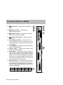
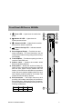
Front Panel–DECserver 900GM
Power LED — Lights when the module has
power.
1
2
3
4
2)
Module OK LED — Lights when the
module passes self-test.
5
6
3)
Network OK LED — Lights when the module
has an active network connection.
4)
Network Activity LED — Indicates network
traffic level.
Seven-Segment Display — Provides error and
status information. For more information, see the
section titled Problem Solving Using the Seven Segment Display.
Flash RAM Slot — Provides an opening in which to
insert the Flash RAM card.
Address Label — Contains the module’s 48-bit
Ethernet Hardware Address.
Reset Switch — Resets the module to factory defaults. To reset: while turning on the power, press and
hold the reset switch until the Module OK LED
flashes, or if the DECserver 900GM is in operational
mode (the seven-segment display shows the “race
track” pattern), hold the switch for 10 seconds. The
module reboots with factory defaults.
Bulk Connectors — Four 68-pin connectors, each
providing 4 full modem control ports or 8 partial modem control ports. When using all four connectors,
you can configure these cables to provide ports in the
following combinations:
1)
5)
6)
7)
8)
9)
7
A
1-8
C
17-24
9
B
9-16
D
25-32
Full
0
4
8
12
16
Partial
32
24
16
8
0
8
LKG-09727–94I
DECserver 900GM Installation
3
Front Panel (Cont.)
NOTES: You can mix port types on connectors A through D but
you cannot mix port types on any single connector.
You can change port type cables at any time but you
must reboot the module when you do so.
4
DECserver 900GM Installation
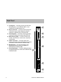
Front Panel–DECserver 900GMx
Power LED — Lights when the module has
power.
1
2
3
4
2)
Module OK LED — Lights when the
module passes self-test.
5
6
3)
Network OK LED — Lights when the module
has an active network connection.
4)
Network Activity LED — Indicates network
traffic level.
Seven-Segment Display — Provides error and
status information. For more information, see the
section titled Problem Solving Using the Seven Segment Display.
Flash RAM Slot — Provides an opening in which to
insert the Flash RAM card.
Address Label — Contains the module’s 48-bit
Ethernet Hardware Address.
Reset Switch — Resets the module to factory defaults. To reset: while turning on the power, press and
hold the reset switch until the Module OK LED
flashes, or if the DECserver 900GMx is in operational
mode (the seven-segment display shows the “race
track” pattern), hold the switch for 10 seconds. The
module reboots with factory defaults.
Bulk Connectors — Two 68-pin connectors, each
providing 4 full modem control ports or 8 partial modem control ports. When using all four connectors,
you can configure these cables to provide ports in the
following combinations:
1)
5)
6)
7)
8)
9)
Full
0
4
8
Partial
16
8
0
7
A
1-8
9
B
9-16
8
LKG-09727–94I
DECserver 900GM Installation
5
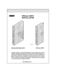
Back Panel
1) Locking tab — Locks the module in the DEChub
900 backplane or in the DEChub ONE. It also
contains the hot-swap switch lever.
2) 48-pin connector — Provides network and power
connections to the module when the module is
installed in a DEChub 900 or DEChub ONE.
3) Grounding bolt — Provides a chassis grounding
connection between the module and a DEChub.
4) Manufacturing label — Lists the module’s part
number, serial number, revision level, and power
requirements.
5) 160-pin connector — Provides network and
power connections to the module when the module
is installed in a DEChub 900 or DEChub ONE.
6) Mounting tab — Secures the module to the
backplane when the module is installed in a
DEChub 900 or DEChub ONE.
7) Grounding fingers — Provides additional chassis
grounding between the module and a DEChub 900
or DEChub ONE.
1
2
3
4
7
5
6
LKG-09728-94I
6
DECserver 900GM Installation
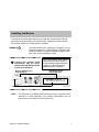
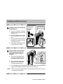
Installing the Module
The module hot-swap feature allows you to install the module into the DEChub
900 without turning off power to the DEChub 900. Seating the module initiates
the powerup sequence if enough power is available.
!
WARNING
1
To avoid personal injury or damage to equipment, do not
install the module into a DEChub 900 or DEChub ONE
unless the module is completely assembled, with the enclosure, bezel, and all faceplates in place.
Compare your module’s power
requirements with the values
shown in the Hub Manager status
display (see examples).
Module’s Manufacturing
Label (Example)
If any of the module’s power requirements exceed the values shown in
the status display, add another power supply (see the DEChub 900
MultiSwitch Owner’s Manual).
Hub Manager Status
Display (Example)
20.0 W
4.0 A
5V
0.1 A 12 V
0.5 A 15 V
Available: 90.5 W
5V: 13.0 A, 15V: 3.5 A
LKG–9062–94I
NOTE:
The 12V power in the DEChub 900 is derived from the 15V power source.
Although it is listed separately in the product specifications, the 12V
requirements are included in the 15V power total.
DECserver 900GM Installation
7
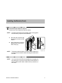
Installing the Module (Cont.)
2
Seat the module into the DEChub
900 MultiSwitch.
Release lever
clicks when
module is
seated.
Hub Manager
status display
a. Place the module’s mounting
tab into a mounting slot on the
DEChub 900.
b. Pivot the module on the mounting tab and align the connectors.
c. Firmly push the module onto the
backplane connectors until the
release lever clicks.
d. Press down on the release lever
to ensure that it is locked.
Mounting
tab
LKG–8711–93I
3
Verify that the module’s Power
LED and the Module OK LED
light (within approximately 2
minutes).
a. The Power LED lights when
the power is applied, then the
module performs a self-test.
b. After the module completes
the self-test, the Module OK
LED lights and remains lit.
LKG–8760-93I
c. The timing depends on the amount of memory installed in the module and the
length of time needed to load the network access software.
NOTE:
8
Refer to the section titled Problem Solving Using the LEDs if the LEDs do
not operate as described.
DECserver 900GM Installation
Installing the Module (Cont.)
4
Connect the port cables as required.
Connect up to four 68-pin bulk connector cables.
NOTE:
All cables should have been installed, tested, and tagged at
the site before you perform this installation.
a. Insert the bulk connector plug
into the port connector on the
module.
b. Using a flat-blade screwdriver,
tighten the two screws at the
ends of the plug.
NOTE:
To disconnect the bulk cables, use a flat-blade screwdriver to
loosen the two screws at the ends of the plug, then disconnect
the cable.
NOTE:
You must reboot the DECserver 900GM after changing the
bulk cable type on a port from a full modem control cable to a
partial modem control cable or data lead only connector, or
vice versa.
DECserver 900GM Installation
LKG–8761-93I
9
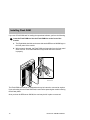
Installing Flash RAM
If you use a Flash RAM card for loading the operational software, perform the following:
1
Insert the Flash RAM card into the Flash RAM slot on the front of the
module.
a. The Digital label should be on the same side as the DECserver 900GM logo on
the front panel of the module.
b. When properly inserted, the Flash RAM card protrudes from the front panel
about 1/4 inch. The Flash RAM card is keyed and cannot be inserted
improperly.
LKG–8091-93I
The Flash RAM card can be hot swapped and may be inserted or removed at anytime.
If you are booting from the Flash RAM card, insert it before powering the module or during
the self-test phase.
Once you boot the DECserver 900GM, the card may be left in place or removed.
10
DECserver 900GM Installation
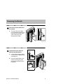
Removing the Module
1
Disconnect all the cables from
the module.
a. To remove the bulk cables,
use a flat-blade screwdriver to
loosen the two screws at the
ends of the plugs, then
disconnect the cable.
LKG–8761-93I
2
Unseat the module from the
DEChub 900 MultiSwitch.
Lift release
lever
a. Lift the release lever located
on the top of the DEChub 900
mounting slot.
b. Pivot the module back on its
bottom mounting tab, and
remove the module from the
backplane.
Mounting
tab
LKG–8717-93I
DECserver 900GM Installation
11
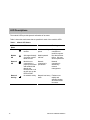
LED Descriptions
The module’s LEDs provide dynamic indications of its status.
Table 1 shows the static states that are possible for each of the module’s LEDs.
Table 1
12
Module LED States
LED
Name
Off
On
Flashing
Power
No power to the
module.
Module receiving
power.
Faulty power
connection or
insufficient power.
Module
OK
After approximately
2 minutes, module
failed self test.
Module passed
self-test.
Non-fatal self-test
failure. Unit may
still be operational.
Network
OK
Module is not
connected to a
properly terminated
and enabled LAN
through the
DEChub 900 or via
the AUI port on the
DEChub ONE.
Network
connection is
operational.
Network
connection is
disabled by
network
management.
Network
Activity
No network activity.
Network has heavy Flashes more
traffic.
rapidly and
appears brighter
as network traffic
increases.
DECserver 900GM Installation
Problem Solving Using the LEDs
When diagnosing a problem with the module, note that the problem is often
indicated by the combined states of the module’s LEDs. Table 2 lists the states of
the LEDs for various error conditions that can occur during initial installation of the
device, along with probable causes and steps you can take to correct the condition.
Normal Powerup
When power to the module is initially turned on, the following events occur:
1. The Power LED lights and remains lit. All other LEDs light and then turn off.
This verifies that the individual LEDs are operational.
2. The module initiates its built-in self-test.
3. After the self-test completes successfully (within approximately 2 minutes),
the Module OK LED lights and remains lit.
4. The remaining LEDs indicate their operational status as described in Table 2.
Problem Solving
Table 2 lists probable causes and corrective actions you can take if the module
LEDs do not function properly.
DECserver 900GM Installation
13
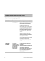
Problem Solving Using the LEDs (Cont.)
Table 2
Problem Solving Using the LEDs
Symptom
Probable Cause
Corrective Action
Power LED is off.
The module is not
receiving power.
Ensure that the release lever (if installing into a DEChub 900) or the locking
L-bracket screw (if installing into a
DEChub ONE) is locked securely.
If installing the module into a
DEChub 900, check the power status
on the Hub Manager status display. If
enough power is available, lift the release lever (if installing the module
into a DEChub ONE, loosen the locking L-bracket screw). Remove the
module.
Inspect the module’s 48-pin and
160-pin connectors for bent, broken,
or dirty pins. If any pins are broken or
bent, replace the module.
If no pins are broken or bent, reinstall
the module into the DEChub.
If the problem persists, replace the
module.
Power LED
is flashing.
The module
connection is faulty.
Lift the release lever, then reseat
the module.
Faulty DEChub 900
slot connection.
Reinstall the module into another slot.
DEChub power
supply is faulty.
If the module is installed in a
DEChub 900, replace the power supply. If the module is installed in a
DEChub ONE, replace the
DEChub ONE.
(continued on next page)
14
DECserver 900GM Installation
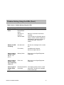
Problem Solving Using the LEDs (Cont.)
Table 2 (Cont.) Problem Solving Using the LEDs
Symptom
Probable Cause
Corrective Action
Module OK LED
is off.
Module does not
have sufficient
power.
Ensure Power LED is on.
Self-test is in
progress.
Wait up to 2 minutes for self-test to
complete.
Self-test failed.
If the LED does not light after approximately 2 minutes, lift the release lever
momentarily to repeat the self-test. If
self-test fails again, replace the
module.
Non-fatal error.
See the error message on the console
port.
Fan is faulty.
Call Multivendor Customer
Services to replace the fan.
Seven-segment
display is flashing “C,” “d,”
or “n”.
Memory failure.
Return the unit to Digital Equipment
Corporation.
Seven-segment
display is flashing or displaying
a solid “8”.
Fatal error.
Return the unit to Digital Equipment
Corporation.
Seven-segment
display shows
a “3”.
Download backoff is If the display persists, there is a loadin progress.
ing problem. See the error message
on the console port.
Module OK LED
is flashing.
DECserver 900GM Installation
15
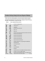
Problem Solving Using the Seven Segment Display
Table 3 shows the codes that appear on the seven-segment display during the
server power-up and initialization internal self-test. The first column indicates a
horizontal view (standalone). The second column indicates a vertical view (hub) of
the codes. The third column describes the codes.
Table 3
Off
Seven Segment Display Codes
Off
No power or display broken
Initial power on
Initialization
DECserver 900 internal test
SIM 1 test
SIM 2 test
DECserver 900 internal test (Flexchannel test and Fan test)
DECserver 900 internal test
DECserver 900 internal test
DECserver 900 internal test
DECserver 900 internal test
Network interface external test
Software loading from or programming Flash RAM card
Requesting load
Load request backoff
Loading
Requesting dump
Dumping
Hardware revision # incompatible with firmware revision #
No SIMs, or wrong type SIMs installed
Rotating
16
Rotating
DECserver 900 is operating correctly. The rotating code is
referred to as the “race track” pattern.
LKG-8099-93I
DECserver 900GM Installation
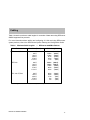
Cabling
Table 4 shows the maximum cable lengths for a number of data rates using DECserver
900GM supported line protocols.
For more information about cabling and configuring of LANs and using DECconnect
system products, refer to the DECconnect System Planning and Configuration Guide.
Table 4
" ! !
&
&
&
&
&
&
#+
#+
#+
#+
#+
#+
&
&
&
&
&
#+
#+
#+
#+
#+
&
&
&
&
&
#+
#+
#+
#+
#+
')
%" +-(" . ') . ($) +,$*+"! ($)
DECserver 900GM Installation
17
Connector Pin Assignments
To install the DECserver 900GM, use either a 68-pin bulk to 50-pin female Telco
adapter (H8586-AA), the 68-pin bulk to 50-pin male Telco cable (BN41C-03), the
68-pin to eight MP8 connectors cable (BN41B-03), or 68-pin to four 25-pin DB
connectors cable (BN41A-03).
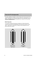
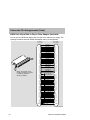
Bulk Connector
The following illustrations show the pin orientations of a 68-pin female bulk
connector on the DECserver 900GM and a 68-pin male bulk connector on the
cable. These figures are followed by a listing of the pin assignments for the
68-pin female bulk connector.
68
34
34
68
35
1
1
35
68-pin female
bulk connector
(DECserver)
68-pin male
bulk connector
(cable)
LKG–09758–94I
18
DECserver 900GM Installation
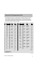
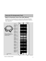
Connector Pin Assignments (Cont.)
The following table lists the pin assignments for the 68-pin female bulk connector
on the DECserver 900GM. Use this information in conjunction with the cable
pinouts shown in the following tables and diagrams. If you are using cables that
are not made by Digital, be sure to follow the pin orientations for the 68-pin male
bulk connector shown on the previous page.
*
Pin
#
Modem Control
Full
Partial
1
2
3
4
5
6
7
8
9
10
11
12
13
14
15
16
17
18
19
20
21
22
23
24
25
26
27
28
29
30
31
32
33
34
TXD
RXD
CTS
DSR
TXD
RXD
CTS
DSR
TXD
RXD
CTS
DSR
TXD
RXD
CTS
DSR
DCD
RI
SMI
DCD
RI
SMI
DCD
RI
SMI
DCD
RI
SMI
TXD
RXD
DSR
CTS
TXD
RXD
DSR
CTS
TXD
RXD
DSR
CTS
TXD
RXD
DSR
CTS
TXD
RXD
DSR
CTS
TXD
RXD
DSR
CTS
TXD
RXD
DSR
CTS
TXD
RXD
DSR
CTS
Data
Leads
Ports
F, P, D*
Pin
Modem
Full
Control
Partial
Data
Leads
Ports
F, P, D*
TXD
RXD
DSR
1, 1, 1
1, 1, 1
1, 1, 1
1, 1, –
2, 2, 2
2, 2, 2
2, 2, 2
2, 2, –
3, 3, 3
3, 3, 3
3, 3, 3
3, 3, –
4, 4, 4
4, 4, 4
4, 4, 4
4, 4, –
–, 5, 5
1, 5, 5
1, 5, 5
1, 5, –
–, 6, 6
2, 6, 6
2, 6, 6
2, 6, –
–, 7, 7
3, 7, 7
3, 7, 7
3, 7, –
–, 8, 8
4, 8, 8
4, 8, 8
4, 8, –
–, Id,–
–, –,
Id
35
36
37
38
39
40
41
42
43
44
45
46
47
48
49
50
51
52
53
54
55
56
57
58
59
60
61
62
63
64
65
66
67
68
GND
GND
RTS
DTR
GND
GND
RTS
DTR
GND
GND
RTS
DTR
GND
GND
RTS
DTR
TXD COM
RXD COM
DTR
RTS
TXD COM
RXD COM
DTR
RTS
TXD COM
RXD COM
DTR
RTS
TXD COM
RXD COM
DTR
RTS
TXD COM
RXD COM
DTR
RTS
TXD COM
RXD COM
DTR
RTS
TXD COM
RXD COM
DTR
RTS
TXD COM
RXD COM
DTR
RTS
TXD COM
RXD COM
DTR
1, 1, 1
1, 1, 1
1, 1, 1
1, 1, –
2, 2, 2
2, 2, 2
2, 2, 2
2, 2, –
3, 3, 3
3, 3, 3
3, 3, 3
3, 3, –
4, 4, 4
4, 4, 4
4, 4, 4
4, 4, –
–, 5, 5
1, 5, 5
1, 5, 5
–, 5, –
–, 6, 6
2, 6, 6
2, 6, 6
–, 6, –
–, 7, 7
3, 7, 7
3, 7, 7
–, 7, –
–, 8, 8
4, 8, 8
4, 8, 8
–, 8, –
Id, –, –
Id, Id,
Id
TXD
RXD
DSR
TXD
RXD
DSR
TXD
RXD
DSR
TXD
RXD
DSR
TXD
RXD
DSR
TXD
RXD
DSR
TXD
RXD
DSR
GND
DSRS
GND
DSRS
GND
DSRS
GND
DSRS
TXD COM
RXD COM
DTR
TXD COM
RXD COM
DTR
TXD COM
RXD COM
DTR
TXD COM
RXD COM
DTR
TXD COM
RXD COM
DTR
TXD COM
RXD COM
DTR
TXD COM
RXD COM
DTR
F = Full modem control
P = Partial modem control
D = Data leads only
LKG-8764-93I
DECserver 900GM Installation
19
Connector Pin Assignments (Cont.)
H8586-AA: 68-pin Bulk to 50-pin Telco Adapter (Included)
You can use the H8586-AA adapter with a 50-pin Telco cable that you supply. The
following illustration shows an H8586-AA adapter and its pin assignments:
50-pin female
Telco Adapter
68-pin male
D-Connector
NOTE: Tie together pins 34
and 68 on the 68-pin connector
to enable the software to
identify the adapter.
1
2
3
5
6
7
9
10
11
13
14
15
17
18
19
21
22
23
25
26
27
29
30
31
34
35
36
37
39
40
41
43
44
45
47
48
49
51
52
53
55
56
57
59
60
61
63
64
65
68
SHELL
TXD PORT 1
RXD PORT 1
DSR PORT 1
TXD PORT 2
RXD PORT 2
DSR PORT 2
TXD PORT 3
RXD PORT 3
DSR PORT 3
TXD PORT 4
RXD PORT 4
DSR PORT 4
TXD PORT 5
RXD PORT 5
DSR PORT 5
TXD PORT 6
RXD PORT 6
DSR PORT 6
TXD PORT 7
RXD PORT 7
DSR PORT 7
TXD PORT 8
RXD PORT 8
DSR PORT 8
TXD COM PORT 1
RXD COM PORT 1
DTR PORT 1
TXD COM PORT 2
RXD COM PORT 2
DTR PORT 2
TXD COM PORT 3
RXD COM PORT 3
DTR PORT 3
TXD COM PORT 4
RXD COM PORT 4
DTR PORT 4
TXD COM PORT 5
RXD COM PORT 5
DTR PORT 5
TXD COM PORT 6
RXD COM PORT 6
DTR PORT 6
TXD COM PORT 7
RXD COM PORT 7
DTR PORT 7
TXD COM PORT 8
RXD COM PORT 8
DTR PORT 8
SHELL
1
2
3
4
5
6
7
8
9
10
11
12
13
14
15
16
17
18
19
20
21
22
23
24
26
27
28
29
30
31
32
33
34
35
36
37
38
39
40
41
42
43
44
45
46
47
48
49
SHELL
LKG–09757–94I
20
DECserver 900GM Installation
Connector Pin Assignments (Cont.)
BN41C-03: 68-pin Bulk to 50-pin Telco Cable (Optional)
The BN41C-03 is recommended for use with the H3117-MA or H3107-M MJ8 to
50-pin Telco patch panel. The following illustration shows a BN41C-03 cable and
its pin assignments:
68-pin
D-Connector
NOTE: Tie together pins 34
and 68 on the 68-pin connector
to enable the software to
identify the cable.
= twisted pair
TXD PORT 1
TDX COM PORT 1
RXD PORT 1
RXD COM PORT 1
DSR PORT 1
DTR PORT 1
TXD PORT 2
TXD COM PORT 2
RXD PORT 2
RXD COM PORT 2
DSR PORT 2
DTR PORT 2
TXD PORT 3
TDX COM PORT 3
RXD PORT 3
RXD COM PORT 3
DSR PORT 3
DTR PORT 3
TXD PORT 4
TXD COM PORT 4
RXD PORT 4
RXD COM PORT 4
DSR PORT 4
DTR PORT 4
TXD PORT 5
TDX COM PORT 5
RXD PORT 5
RXD COM PORT 5
DSR PORT 5
DTR PORT 5
TXD PORT 6
TXD COM PORT 6
RXD PORT 6
RXD COM PORT 6
DSR PORT 6
DTR PORT 6
TXD PORT 7
TDX COM PORT 7
RXD PORT 7
RXD COM PORT 7
DSR PORT 7
DTR PORT 7
TXD PORT 8
TXD COM PORT 8
RXD PORT 8
RXD COM PORT 8
DSR PORT 8
DTR PORT 8
1
35
2
36
3
37
5
39
6
40
7
41
9
43
10
44
11
45
13
47
14
48
15
49
17
51
18
52
19
53
21
55
22
56
23
57
25
59
26
60
27
61
29
63
30
64
31
65
34
68
50-pin
Telco Adapter
1
26
2
27
3
28
4
29
5
30
6
31
7
32
8
33
9
34
10
35
11
36
12
37
13
38
14
39
15
40
16
41
17
42
18
43
19
44
20
45
21
46
22
47
23
48
24
49
LKG-8363-93I
DECserver 900GM Installation
21
Connector Pin Assignments (Cont.)
BN41A-03: 68-pin to Four 25-pin DB Octopus Cable (Optional)
Use this cable on DECserver bulk connectors A through D to provide four
full-modem control connections for each serial port. The following illustration shows
a 68-pin bulk connector to four 25-pin DB connector cable. You can connect the
25-pin DB connectors directly to modems. You must use a crossover adapter or
crossover cable for terminal interconnections. The wire size should be 26 or 28GA,
shielded or unshielded, twisted- or untwisted-pair. On the 68-pin connector, tie pins
67 and 68 together to enable the software to identify the cable. Table 5 lists the
appropriate pin assignments.
NOTE:
You can mix cable BN41A-03 and cable BN41B-03 on serial ports
A through D to create four full modem control connections on one
port and eight partial modem control connections on another.
LKG–4730–93I
Recommended Wire Pairings for each DB25 Connector
25-pin D-shell Connector
DSRS
SMI
RI
DCD
GND
DTR
DSR
CTS
RTS
RXD
TXD
SHIELD
23
12
22
8
7
20
6
5
4
3
2
1
Pair
Pair
Pair
Pair
Pair
Wires do not need to be
twisted. If they are, they
must be paired as shown
in the diagram.
Pair
LKG–09760–94I
22
DECserver 900GM Installation
Connector Pin Assignments (Cont.)
Table 5
25-pin DB
Number
68-pin to Four 25-pin DB Octopus Cable Pinout
Twisted
Pairings
1
P i {
Pair
Pair {
P i {
Pair
Pair {
Pair {
Pair {
2
P i {
Pair
P i {
Pair
Pair {
Pair {
Pair {
Pair {
25-pin DB
Pin Number
68-pin
Pin Number
Full Modem
Control Signal
1 and HOUSING
HOUSING
SHIELD
2
1
TXD
7
35
GND
3
2
RXD
7
36 and 52
GND
4
37
RTS
5
3
CTS
20
6
8
22
12
23
38
4
18
19
20
53
DTR
DSR
DCD
RI
SMI
DSRS
1 and HOUSING
HOUSING
SHIELD
2
5
TXD
7
39
GND
3
6
RXD
7
40 and 56
GND
4
41
RTS
5
7
CTS
20
6
8
22
12
23
42
8
22
23
24
57
DTR
DSR
DCD
RI
SMI
DSRS
(continued on next page)
DECserver 900GM Installation
23
Connector Pin Assignments (Cont.)
Table 5 (Cont.) 68-pin to Four 25-pin DB Octopus Cable Pinout
25-pin DB
Number
Twisted
Pairings
3
P i {
Pair
P i {
Pair
P i {
Pair
Pair {
Pair {
Pair {
4
P i {
Pair
P i {
Pair
P i {
Pair
Pair {
Pair {
Pair {
NOTE:
24
25-pin DB
Pin Number
68-Pin
Pin Number
Full Modem
Control Signal
1 and HOUSING
HOUSING
SHIELD
2
9
TXD
7
43
GND
3
10
RXD
7
44 and 60
GND
4
45
RTS
5
11
CTS
20
6
8
22
12
23
46
12
26
27
28
61
DTR
DSR
DCD
RI
SMI
DSRS
1 and HOUSING
HOUSING
SHIELD
2
13
TXD
7
47
GND
3
14
RXD
7
48 and 64
GND
4
49
RTS
5
15
CTS
20
6
8
22
12
23
50
16
30
31
32
65
DTR
DSR
DCD
RI
SMI
DSRS
On the 68-pin connector, tie pins 67 and 68 together to enable the
software to identify the cable.
DECserver 900GM Installation
Connector Pin Assignments (Cont.)
BN41B-03: 68-pin to Eight 8-pin MP Octopus Cable (Optional)
Use this cable on DECserver bulk connectors A through D to provide eight partial
modem control connections for each serial port and with the H8585 series
adapters for modem and personal computer (PC) connections. You can also use
this cable with the H3117-NA/NB or H3107-N MJ8 patch panel to provide a
DECserver 900TM-type MJ8 interface. The following illustration shows a 68-pin
to eight 8-pin MP8 connector cable. Table 6 shows the appropriate pin
assignments.
LKG–4730–93I
Recommended Wire Pairings for each MP8 Connector
8-pin Modular Jack
Wires do not need to be
twisted. If they are, they
must be paired as shown
in the diagram.
DSR
DTR
TXD
RTS
CTS
TXD GND
RXD
RXD GND
8
7
6
5
4
3
2
1
Pair
Pair Pair
Pair
LKG–09759–94I
DECserver 900GM Installation
25
Connector Pin Assignments (Cont.)
NOTE:
Table 6
8-pin MP
Number
You can mix cable BN41A-03 and cable BN41B-03 on serial ports
A through D to create four full modem control connections on one
port and eight partial modem control connections on another.
68-pin to Eight 8-pin MP Octopus Pinout
Twisted
Pairings
1
Pair
P i {
Pair
P i {
Pair
P i {
Pair
P i {
8-pin MP
Number
Twisted
Pairings
2
Pair
P i {
Pair
P i {
Pair
P i {
Pair
P i {
8-pin MP
Pin Number
68-pin
Pin Number
Partial Modem
Control Signal
6
1
TXD
3
35
TXD COM
2
2
RXD
1
36
RXD COM
8
3
DSR
7
37
DTR
4
4
CTS
5
38
RTS
8-pin MP
Pin Number
68-pin
Pin Number
Partial Modem
Control Signal
6
5
TXD
3
39
TXD COM
2
6
RXD
1
40
RXD COM
8
7
DSR
7
41
DTR
4
8
CTS
5
42
RTS
(continued on next page)
26
DECserver 900GM Installation
Connector Pin Assignments (Cont.)
Table 6 (Cont.) 68-pin to Eight 8-pin MP Octopus Pinout
8-pin MP
Number
Twisted
Pairings
3
Pair
P i {
Pair
P i {
Pair
P i {
Pair
P i {
8-pin MP
Number
Twisted
Pairings
4
Pair
P i {
Pair
P i {
Pair
P i {
Pair
P i {
8-pin MP
Pin Number
68-pin
Pin Number
Partial Modem
Control Signal
6
9
TXD
3
43
TXD COM
2
10
RXD
1
44
RXD COM
8
11
DSR
7
45
DTR
4
12
CTS
5
46
RTS
8-pin MP
Pin Number
68-pin
Pin Number
Partial Modem
Control Signal
6
13
TXD
3
47
TXD COM
2
14
RXD
1
48
RXD COM
8
15
DSR
7
49
DTR
4
16
CTS
5
50
RTS
(continued on next page)
DECserver 900GM Installation
27
Connector Pin Assignments (Cont.)
Table 6 (Cont.) 68-pin to Eight 8-pin MP Octopus Pinout
8-pin MP
Number
Twisted
Pairings
5
Pair
P i {
Pair
P i {
Pair
P i {
Pair
P i {
8-pin MP
Number
Twisted
Pairings
6
Pair
P i {
Pair
P i {
Pair
P i {
Pair
P i {
8-pin MP
Pin Number
68-pin
Pin Number
Partial Modem
Control Signal
6
17
TXD
3
51
TXD COM
2
18
RXD
1
52
RXD COM
8
19
DSR
7
53
DTR
4
20
CTS
5
54
RTS
8-pin MP
Pin Number
68-pin
Pin Number
Partial Modem
Control Signal
6
21
TXD
3
55
TXD COM
2
22
RXD
1
56
RXD COM
8
23
DSR
7
57
DTR
4
24
CTS
5
58
RTS
(continued on next page)
28
DECserver 900GM Installation
Connector Pin Assignments (Cont.)
Table 6 (Cont.) 68-pin to Eight 8-pin MP Octopus Pinout
8-pin MP
Number
Twisted
Pairings
7
Pair
P i {
Pair
P i {
Pair
P i {
Pair
P i {
8-pin MP
Number
Twisted
Pairings
8
Pair
P i {
Pair
P i {
Pair
P i {
Pair
P i {
8-pin MP
Pin Number
68-pin
Pin Number
Partial Modem
Control Signal
6
25
TXD
3
59
TXD COM
2
26
RXD
1
60
RXD COM
8
27
DSR
7
61
DTR
4
28
CTS
5
62
RTS
8-pin MP
Pin Number
68-pin
Pin Number
Partial Modem
Control Signal
6
29
TXD
3
63
TXD COM
2
30
RXD
1
64
RXD COM
8
31
DSR
7
65
DTR
4
32
CTS
5
66
RTS
NOTES: On the 68-pin connector, tie pins 33 and 68 together to enable the
software to identify the cable.
The wire size should be 28GA or 26GA unshielded twisted pair.
DECserver 900GM Installation
29
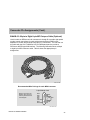
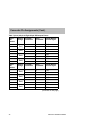
BN41D-03: 68-pin to Eight 25-pin DB Octopus Cable (Optional)
Use this cable on DECserver bulk connectors A through D to provide eight partial
modem control connections for each serial port. The following illustration shows a
68-pin bulk connector to eight 25-pin DB connector cable. You can connect the
25-pin DB connectors directly to modems. You must use a crossover adapter or
crossover cable for terminal interconnections. The wire size should be 26 or
28GA, shielded or unshielded, twisted- or untwisted-pair. On the 68-pin
connector, tie pins 33 and 68 together to enable the software to identify the cable.
Table 7 lists the appropriate pin assignments.
LKG–10312–96I
Recommended Wire Pairings for each MP25 Connector
25–pin Modular Jack
Wires do not need to be
twisted. If they are, they
must be paired as shown
in the diagram.
DTR
RXD GND
25
24 12
Pair pins 2 and 7
11
Pair pins 6 and 20
23 10
22 9
21
Pair
20 8
19 7 GND
18 6 DSR
17 5 CTS
Pair
16 4 RTS
15 3 RXD
14 2 TXD
13 1
LKG–10313–96I
30
DECserver 900GM Installation
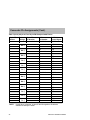
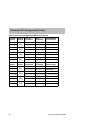
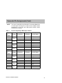
Connector Pin Assignments (Cont.)
NOTE:
Table 7
25-pin
MP
Number
You can mix cable BN41A-03, BN41B–03, and cable BN41D-03
on serial ports A through D to create four full modem control
connections on one port and eight partial modem control
connections on another.
68-pin to Eight 25-pin DB Octopus Pinout
Twisted
Pairings
1
Pair
P i {
Pair
P i {
P i {
Pair
Pair
P i {
25-pin
MP
Number
Twisted
Pairings
2
Pair
P i {
Pair
P i {
Pair
P i {
Pair
P i {
25-pin MP
Pin Number
68-pin
Pin Number
Partial Modem
Control Signal
2
1
TXD
7
35
GND
3
2
RXD
7
36
GND
6
3
DSR
20
37
DTR
5
4
CTS
4
38
RTS
25-pin MP
Pin Number
68-pin
Pin Number
Partial Modem
Control Signal
2
5
TXD
7
39
GND
3
6
RXD
7
40
GND
6
7
DSR
20
41
DTR
5
8
CTS
4
42
RTS
(continued on next page)
DECserver 900GM Installation
31
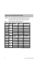
Connector Pin Assignments (Cont.)
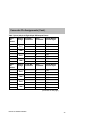
Table 7 (Cont.) 68-pin to Eight 25-pin DB Octopus Pinout
25-pin
MP
Number
Twisted
Pairings
3
Pair
P i {
Pair
P i {
Pair
P i {
Pair
P i {
25-pin
MP
Number
Twisted
Pairings
4
Pair
P i {
Pair
P i {
Pair
P i {
Pair
P i {
25-pin MP
Pin Number
68-pin
Pin Number
Partial Modem
Control Signal
2
9
TXD
7
43
GND
3
10
RXD
7
44
GND
6
11
DSR
20
45
DTR
5
12
CTS
4
46
RTS
25-pin MP
Pin Number
68-pin
Pin Number
Partial Modem
Control Signal
2
13
TXD
7
47
GND
3
14
RXD
7
48
GND
6
15
DSR
20
49
DTR
5
16
CTS
4
50
RTS
(continued on next page)
32
DECserver 900GM Installation
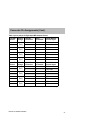
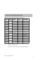
Connector Pin Assignments (Cont.)
Table 7 (Cont.) 68-pin to Eight 25-pin DB Octopus Pinout
25-pin
MP
Number
Twisted
Pairings
5
Pair
P i {
Pair {
Pair
P i {
Pair {
25-pin
MP
Number
Twisted
Pairings
6
Pair
P i {
Pair {
Pair
P i {
Pair {
25-pin MP
Pin Number
68-pin
Pin Number
Partial Modem
Control Signal
2
17
TXD
7
51
GND
3
18
RXD
7
52
GND
6
19
DSR
20
53
DTR
5
20
CTS
4
54
RTS
25–pin MP
Pin Number
68-pin
Pin Number
Partial Modem
Control Signal
2
21
TXD
7
55
GND
3
22
RXD
7
56
GND
6
23
DSR
20
57
DTR
5
24
CTS
4
58
RTS
(continued on next page)
DECserver 900GM Installation
33
Connector Pin Assignments (Cont.)
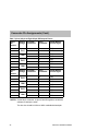
Table 7 (Cont.) 68-pin to Eight 25-pin DB Octopus Pinout
25-pin
MP
Number
Twisted
Pairings
7
Pair
P i {
Pair {
Pair
P i {
Pair {
25-pin
MP
Number
Twisted
Pairings
8
Pair
P i {
Pair {
Pair
P i {
Pair {
25-pin MP
Pin Number
68-pin
Pin Number
Partial Modem
Control Signal
2
25
TXD
7
59
GND
3
26
RXD
7
60
GND
6
27
DSR
20
61
DTR
5
28
CTS
4
62
RTS
25-pin MP
Pin Number
68-pin
Pin Number
Partial Modem
Control Signal
2
29
TXD
7
63
GND
3
30
RXD
7
64
GND
6
31
DSR
20
65
DTR
5
32
CTS
4
66
RTS
NOTES: On the 68-pin connector, tie pins 33 and 68 together to enable the
software to identify the cable.
The wire size should be 28GA or 26GA unshielded twisted pair.
34
DECserver 900GM Installation
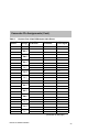
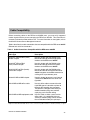
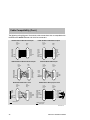
Cable Compatibility
Before connecting cables to the DECserver 900GM ports, you must verify supported
modem signals with the person managing the DECserver 900GM. This information is
necessary to determine what cables to use. For more information on the signals, refer to
the Network Access Server Management manual.
(" !"/ .&"/ 0%" (" +**" 0&+*/ 0%0 ." +),0&(" 3&0% 0%" /".2". 0%".*"0 *! /".&( (&*" +**" 0+./
Table 8 5 0+ )("
)+!") !,0".
/" 0%&/ !,0". 3&0% 0%" +. 0%"
5 (" 0+ +**" 0 %&$%5/,""!
)+!")/ 0+ 0%" /".2". 5 0+ )(" )+!") !,0".
/" 0%&/ !,0". 3&0% 0%" +. 0%"
5 (" 0+ +**" 0 (+35/,""!
)+!")/ 0+ 0%" /".2". 5 0+ #")("
*1((5)+!") !,0".
/" 0%&/ !,0". 3&0% 0%" +. 0%"
5 (" 0+ +*2".0 0%" /".2".
+**" 0+. 0+ 0%" +**" 0+. #+.
(&*$ 0+ /4* %.+*+1/ ,+.0/
5 0+ !,0".
/" 0%&/ !,0". 0+ +*2".0 /".&( ,+.0 0+
/".2". 0".)&*( /".2". +*5
#&$1.0&+*
0+ +##& " ("
/" 0%&/ +##& " (" 0+ +**" 0 #.+) 0%"
5,&* ,+.0 +# 0".)&*( +. ,.&*0". 0+
0%" 5,&* # ",(0" !0 +**" 0+.
%" &/ +*#&$1."! 3&0% +*" 5,&*
)+!&#&"! )+!1(. ,(1$ +*" /0*!.!
5,&* ,(1$ *! .+//+2". 3&.&*$
0+ "-1&,)"*0 ("
/" 0%&/ (" / "&0%". ,0 % +.! +.
+##& " (" 0 &/ +*#&$1."! 3&0% /0*5
!.! 5,&* )+!1(. ,(1$/ 3%& % +**" 0
#+1. 1*/%&"(!"! 03&/0"! ,&./ ,&*50+5,&*
!,0"./
5 *! 5 ." *+0 #+. +**" 0&+* 0+ ,1(& *"03+.'/ &* 3"!"* ".)*4 +. ,*
DECserver 900GM Installation
35
Cable Compatibility (Cont.)
H8585-AC MP8 to DB25 Modem Adapter
8-pin
Modular
Jack
DSR
DTR
TXD
RTS
CTS
TXD GND
RXD
RXD GND
8
7
6
5
4
3
2
1
H8585-AB MP8 to DB25 Modem Adapter
8-pin
Modular
Jack
DB25
Plug
6
20
2
4
5
7
3
DSR
DTR
TXD
RTS
CTS
SIG GND
RXD
DCD
DTR
TXD
DSRS
RI
TXD GND
RXD
RXD GND
H8585-AA MP8 to DB9 Null-Modem Adapter
8-pin
Modular
Jack
8-pin
Modular
Plug
9
8
7
6
5
4
3
2
1
RI
CTS
RTS
DRDY
GND
DTR
TXD
RXD
DCD
BN24H MP8 to MP6 Office Cable
8-pin
Modular
Plug
DSR
DTR
TXD
TXD GND
RXD
RXD GND
8
7
6
5
4
3
2
1
Twisted pairs
DSR
DTR
TXD
CTS
TXD GND
RXD
RXD GND
8
7
6
5
4
3
2
1
8-pin
Modular
Plug
DSR
RXD
RXD GND
TXD GND
TXD
DTR
DCD
DTR
TXD
DSRS
RI
SIG GND
RXD
RTS
6-pin
Modular
Jack
6
5
4
3
2
1
DSR
RXD
RXD GND
TXD GND
TXD
DTR
BN25G MP8 to MP8 Equipment Cable
6-pin
Modular
Plug
6
5
4
3
2
1
8
20
2
23
22
7
3
4
H8584-AC MP8 to MMJ Adapter
DB9
Jack
8
7
6
5
4
3
2
1
DSR
DTR
TXD
RTS
CTS
TXD GND
RXD
RXD GND
8
7
6
5
4
3
2
1
DB25
Plug
RXD GND
RXD
TXD GND
* CTS or RI
* RTS or DSRS
TXD
DTR
* DSR or DCD
1
2
3
4
5
6
7
8
8-pin
Modular
Plug
1
2
3
4
5
6
7
8
RXD GND
RXD
TXD GND
* CTS or RI
* RTS or DSRS
TXD
DTR
* DSR or DCD
*Software selectable
Twisted pairs
LKG-7294–92I
36
DECserver 900GM Installation
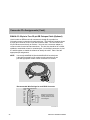
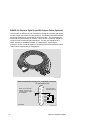
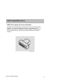
Cable Compatibility (Cont.)
H8587-AA Loopback Connector (Provided)
The DECserver 900GM product includes a 68-pin male to 8-pin MJ loopback
connector. You can use the loopback connector on connector A of the
DECserver to provide a console port, to set up a loopback connection, and to
perform loopback testing. The following diagram represents the loopback
connector.
LKG–09729–94I
DECserver 900GM Installation
37
Product Specifications
Table 9 lists the DECserver 900GM physical, environmental, and certification
specifications.
Table 9
Operating Specifications
Parameter
DECserver 900GM
DECserver 900GMx
Operating Temperature1
5° C – 50° C (41° F – 122° F)
5° C – 50° C (41° F – 122° F)
Relative Humidity
10% to 95% noncondensing
10% to 95% noncondensing
Altitude
Sea level to 4900 m (16K ft)
Sea level to 4900 m (16K ft)
Power
28.7 W, total power
4.0 A, 5Vdc
0.1 A, 12Vdc2
0.5 A, 15Vdc
18.2 W, total power
2.5 A, 5Vdc
0.1 A, 12Vdc2
0.3 A, 15Vdc
Operating Environment
Connectors
GM module has four 68-pin bulk connectors.
GMx module has two 68-pin bulk connectors.
DEChub ONE has: one 8-pin MJ, one DB-9, and one 15-pin D-Sub AUI connector.
DEChub ONE-MX has: one 8-pin MJ, one 6-pin MJ (OBR), one DB-9, one 15-pin D-Sub,
and one redundant power connector (D-Sub).
Physical
Height
44.45 cm (17.5 in)
Width
4.45 cm (1.75 in)
Depth
15.25 cm (6 in); 25.40 cm
(10.0 in) with a DEChub ONE
docking station
Weight
1.8 kg (4 lb)3
Certification
CE, CSA, FCC,TÜV, UL, VCCI.
1 For
sites above 4900 m (16,000 ft), decrease the operating temperature specification
by 1.8° C for each 1000 m or 3.2°F for each 3200 ft.
38
2
The 12V power in the DEChub 900 is derived from the 15V power source. Although it is
listed separately in the product specification, the 12V requirements are included in the 15V
power total.
3
Include an additional 1.59 kg (3.5 lb) when attached to a DEChub ONE; when attached to
a DEChub ONE-MX, add 2.10 kg (4.63 lb).
DECserver 900GM Installation
Product Specifications (Cont.)
Table 10 lists the DECserver 900GM acoustical specifications.
Table 10 Acoustical Specifications
Acoustics — Declared values per ISO 9296 and ISO 77791
Sound Power Level
LWAd, B
Sound Pressure Level
LpAm, dBA
(bystander positions)
Idle/Operate
Idle/Operate
DSRVY
4.8
34
DSRVY + DEHUA
5.2
39
DSRVY + DEF1H
5.2
38
Product
Schallemissionswerte — Werteangaben nach ISO 9296 und ISO 7779/DIN EN277792
Schalleistungspegel
LWAd, B
Schalldruckpegel
LpAm, dBA
(Zuschauerpositionen)
Leerlauf/Betrieb
Leerlauf/Betrieb
DSRVY
4,8
34
DSRVY + DEHUA
5,2
39
DSRVY + DEF1A
5,2
38
Produkt
1
Current values for specific configurations are available from Digital Equipment Corporation
representatives. 1 B = 10 dBA.
2
Aktuelle Werte für spezielle Ausrüstungsstufen sind über die Digital Equipment
Vertretungen erhältlich. 1 B = 10 dBA.
DECserver 900GM Installation
39
HOW TO ORDER ADDITIONAL DOCUMENTATION
DIRECT TELEPHONE ORDERS
In Continental USA
call 1-800-DIGITAL
(1-800–344-4825)
In Canada
call 1–800–267–6215
In New Hampshire,
Alaska or Hawaii
call 1–603–884–6660
ELECTRONIC ORDERS (U.S. ONLY)
Dial 1-800-dec-demo with any VT100 or VT200
compatible terminal and a 1200 baud modem.
If you need assistance, call 1-800-DIGITAL (1-800-344-4825)
DIRECT MAIL ORDERS (U.S. and Puerto Rico*)
DIGITAL EQUIPMENT CORPORATION
P.O. Box CS2008
Nashua, New Hampshire 03061
DIRECT MAIL ORDERS (Canada)
DIGITAL EQUIPMENT OF CANADA LTD.
940 Belfast Road
Ottawa, Ontario, Canada K1G 4C2
Attn: A&SG Business Manager
INTERNATIONAL
DIGITAL EQUIPMENT CORPORATION
A&SG Business Manager
c/o Digital’s local subsidiary
or approved distributor
Internal orders should be placed through U.S. Software Supply Business (SSB),
Digital Equipment Corporation, 8 Cotton Rd. Nashua, NH. 03063-1260
*Any prepaid order from Puerto Rico must be placed
with the Local Digital Subsidiary:
809–754–7575