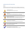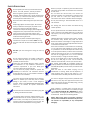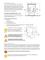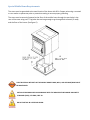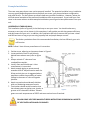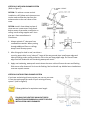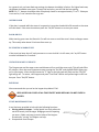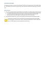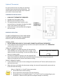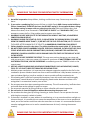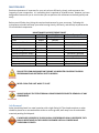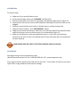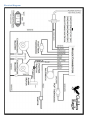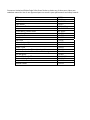
1
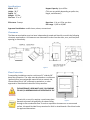
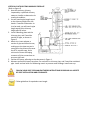
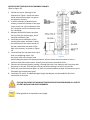
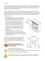
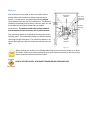
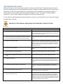
THE MONROE WOOD PELLET STOVE BY Operating & Installation Manual Manufactured by: National Steelcrafters of Texas, LLC. Arlington, TX www.goldeneaglestoves.com SAFETY INFORMATION IF YOUR APPLIANCE IS NOT PROPERLY INSTALLED A HOUSE FIRE MAY RESULT. FOR YOUR SAFETY, FOLLOW THE INSTALLATION DIRECTIONS. CONTACT LOCAL BUILDING OR FIRE OFFICIALS ABOUT RESTRICTIONS AND INSTALLATION INSPECTION REQUIREMENTS IN YOUR AREA. PLEASE READ THIS ENTIRE MANUAL BEFORE INSTALLATION AND USE OF THIS PELLET FUEL‐ BURNING ROOM HEATER. FAILURE TO FOLLOW THESE INSTRUCTIONS COULD RESULT IN PROPERTY DAMAGE, BODILY INJURY, OR EVEN DEATH. SAVE THIS MANUAL FOR FUTURE REFERENCE PROFESIONAL INSTALLATION IS HIGHLY RECOMMENDED Golden Eagle Stove Company 05/09 Table of Contents WARNINGS AND SAFETY PRECAUTIONS ....................................................................................................... 3 SAFETY PRECAUTIONS .................................................................................................................................... 4 INTRODUCTION ............................................................................................................................................. 5 VENTING ........................................................................................................................................................ 6 Equivalent Vent Length (EVL) .................................................................................................................... 6 Horizontal Pipe .......................................................................................................................................... 7 Multiple Elbows ........................................................................................................................................ 7 Vent Terminations .................................................................................................................................... 7 INSTALLATION ............................................................................................................................................... 8 Preparation ............................................................................................................................................... 8 Specifications ............................................................................................................................................ 9 Clearances ................................................................................................................................................. 9 Floor Protection ........................................................................................................................................ 9 Combustion Air Supply ............................................................................................................................ 10 Electrical Installation ............................................................................................................................... 10 Special Mobile Home Requirements ...................................................................................................... 11 Example Installations .............................................................................................................................. 12 OPERATION ................................................................................................................................................. 16 Button Controls ....................................................................................................................................... 16 Proper Fuel .............................................................................................................................................. 18 Pre‐Start‐Up Check .................................................................................................................................. 18 Building a Fire .......................................................................................................................................... 19 Damper Control ...................................................................................................................................... 19 Optional Thermostat ............................................................................................................................... 22 Operating Safety Precautions ................................................................................................................. 23 MAINTENANCE ............................................................................................................................................ 24 Ash Removal ............................................................................................................................................ 24 Cleaning ................................................................................................................................................... 26 Blowers ................................................................................................................................................... 27 Chimney Cleaning ............................................................................................................................... 28 TROUBLESHOOTING GUIDE ........................................................................................................................ 29 Electrical Diagram ................................................................................................................................... 34 WARNINGS AND SAFETY PRECAUTIONS SYMBOLS Throughout the manual you will find symbols used in order to highlight an important piece of information. Below you will see an example of those symbols and a definition of their meaning. IMPORTANT SAFETY NOTE Read carefully and be sure to follow all directions SAFETY NOTE Important information to avoid damage to the unit or potential safety concern. Read carefully and be sure you fully understand intent and meaning. DANGER OF ELECTRICAL SHOCK While performing this action there is the possibility of electrical shock. Be sure that the unit is disconnected from power while performing this action. IMPORTANT PIECE OF INFORMATION Read carefully and be sure you fully understand the meaning and intent THIS IS AN ACTION THAT SHOULD BE AVOIDED Read carefully and do NOT do this. THIS IS SOMETHING THAT SHOULD BE CHECKED Read carefully and be sure to follow the instructions provided. SAFETY PRECAUTIONS Never try to repair or replace any part of the stove unless instructions are provided. A trained technician should do all other work. Do not throw this manual away. This manual has important operating and maintenance instructions that you will need at a later time. Always follow the instructions in this manual. Read the manual thoroughly. Do not operate your stove if you smell smoke coming from it. Turn it off, monitor it, and call your dealer. Never use gasoline, gasoline‐type lantern fuel, kerosene, charcoal lighter fluid, or similar liquids to start or “freshen up” a fire in this stove. Keep all such liquids well away from the stove while in use. Never block free airflow through the open vents of the stove. Do not place clothing or other flammable items on or near the stove. Keep foreign objects out of the hopper. Be sure that when you add fuel to the hopper, the pellets or corn that you are using is free of foreign material. The stove will not operate during a power outage. If an outage does occur, keep the stove door closed, and open a window if any smoke spills into the room. Adequate vertical vent pipe on the exhaust will prevent smoke from entering the home. The viewing door must be closed and latched during normal operation. Do not operate the stove if the flame becomes dark and sooty or if the burn pot overfills with fuel. Turn the stove off, inspect it, and call your dealer or a qualified, trained technician. CAUTION: Hot while in operation. Keep children, clothing, and furniture away. Contact may cause skin burns. Educate all children of the danger of a high temperature stove. Young children should be supervised when they are in the same room as the stove. If the stove is installed in a room without air conditioning, or in an area where direct sunlight can shine on the unit, it is possible this can cause the temperature of the stove to rise to operational levels; one of the sensors could then make the stove start on its own. It is recommended that the stove be unplugged when not in use for extended amounts of time (i.e. during the summer months). Do not use an adapter plug or sever the grounding plug. Do not use a GFCI plug or circuit. Do not route the electrical cord underneath, in front of, or over the stove. The exhaust system must be completely airtight and properly installed. The exhaust vent joints must be sealed with RTV 500°F (260°C) silicone sealant, and with UL‐181‐ AP foil tape. Allow the stove to cool before carrying out any maintenance or cleaning. Ashes must be disposed in a metal container with a tight lid and placed on a non‐ combustible surface well away from the home structure. Disconnect the power cord before performing any maintenance or repairs on the stove. NOTE: Turning the stove “off” does not disconnect all power from the stove. DO NOT open the viewing door during the start up period. Do not unplug the stove if you suspect a malfunction. Turn the stove off, inspect it, and call your dealer or qualified, trained technician. Contact your local building officials to obtain a permit and information on any installation restrictions or inspection requirements in your area. Notify your insurance company of this stove as well. This unit must be properly installed to prevent the possibility of a house fire. The instructions must be strictly adhered to. Do not use makeshift methods or compromise in the installation. Your stove requires periodic maintenance and cleaning. Failure to maintain your stove may lead to smoke spillage in your home, or even a more dangerous situation. Refer to the MAINTENANCE SECTION of this manual or our website for specific maintenance instructions. This stove must be connected to a standard 3 prong 120 V., 60 Hz grounded electrical outlet. When installed in a mobile home, the stove must be bolted to the floor, have outside air connected (see page 3), and NOT BE INSTALLED IN A BEDROOM (Per H.U.D. requirements). The integrity of the floor and ceiling must be maintained. Check with local building officials. The exhaust system should be checked regularly. It is recommended that the exhaust system be inspected once a month, or for every ton of pellets burned. At a minimum, even if burning less than a ton per year, the exhaust should be checked twice a burning season. Golden Eagle Stoves grants no warranty, implied or stated, for the installation or maintenance of your stove, and assumes no responsibility of any consequential damage(s). This stove is designed and approved for pelletized wood fuel and corn only. Any other type of fuel burned in this heater will void the warranty and safety listing, and may result in a hazardous condition. INTRODUCTION Thank you for purchasing the Golden Eagle Wood Pellet Burning Stove. You are now prepared to burn wood in the most efficient, convenient way possible. To achieve the safest, most efficient and most enjoyable performance from your stove, you must do three things: 1) Install it properly; 2) Operate it correctly; and 3) Maintain it regularly. The purpose of this manual is to help you do all three. This stove has been independently tested to ASTM E1509‐04 Standard Specification for Room Heaters, Pellet Fuel Burning Type 1, ULC/ORD 1482‐90 Standard for Solid Fuel Room Heaters, and Oregon Administrative Rules for Mobile Homes (814‐ 23‐900 through 814‐23‐909) and Installation as a Stove Heater. This appliance is designed specifically for use only with pelletized wood. It is designed for residential installation according to current national and local building codes as a freestanding room heater. It is also approved as a mobile home heater which is designed for connection to an outside combustion air source. This stove is designed to provide the optimum proportions of fuel and air to the fire in order to burn almost free of smoke and soot. Any blockage of the air supply to or from the stove will seriously degrade its performance and will be evidenced by a smoking exhaust and a sooting window. For best operation the ash content of the pellet fuel should be less than 1% and the calorific value approximately 8200 BTU/LB. Avoid high ash content fuels because this will rapidly fill up the burn pot and eventually cut off the combustion air supply. PLEASE READ THIS ENTIRE MANUAL BEFORE INSTALLATION AND USE OF THIS PELLET FUEL‐ BURNING ROOM HEATER. FAILURE TO FOLLOW THESE INSTRUCTIONS COULD RESULT IN PROPERTY DAMAGE, BODILY INJURY OR EVEN DEATH. Keep this manual handy for future reference. THIS PELLET STOVE, WHEN INSTALLED, MUST BE ELECTRICALLY GROUNDED IN ACCORDANCE WITH LOCAL CODES, OR IN THE ABSENCE OF LOCAL CODES, WITH THE NATIONAL ELECTRICAL CODE, ANSI/NFPA 70. The authority having jurisdiction (such as municipal building department, fire department, fire prevention bureau, etc.) should be consulted before installation to determine the need to obtain a permit. THE STOVE WILL NOT OPERATE USING NATURAL DRAFT OR WITHOUT A POWER SOURCE FOR THE BLOWER SYSTEMS AND FUEL FEED SYSTEM AND MUST NOT BE BURNED WITH ANY TYPE OF FUEL BESIDES WOOD PELLETS. COMMERCIAL AND INDUSTRIAL INSTALLATIONS OF PELLET STOVES SHOULD NOT BE USED SINCE OPERATIONAL CONTROL IS OFTEN NOT WELL MANAGED IN THESE SETTINGS. WARRANTY REGISTRATION To receive full warranty coverage, you will need to show evidence of the date you purchased your stove. We suggest that you make a copy and attach your sales invoice to this manual, so that you will have all the information you need in one place should the need for service or information occur. Also be sure to complete the warranty registration form on our webpage (preferred method) or mail in the one that came with the stove. When registering your stove for warranty a copy of the sales invoice must be included either in electronic format if registered via the internet, or a legible copy if you mail in the warranty registration card that came with your stove. VENTING The choices you make when determining how your vent pipe is configured is very important and will have an impact on the performance of your unit. In order to get the best performance from your stove we highly encourage you to follow all installation directions in this manual. It will save you a great deal of time and trouble if you properly vent your unit. The Monroe is certified for use with listed TYPE L‐Vent, 3” or 4” diameter in size. The stove was tested with Simpson Duravent brand. Class “A” chimney is not required. Refer to the instructions provided by the vent manufacturer, especially when passing through a wall, ceiling or roof. THIS IS A PRESSURIZED EXHAUST SYSTEM. ALL VENT CONNECTOR JOINTS MUST BE SEALED WITH 500F (260C) RTV SILICONE SEALANT TO ENSURE CONSISTENT PERFORMANCE AND AVOID SMOKE SPILLAGE. ALL HORIZONTAL CONNECTOR JOINTS MUST BE SEALED WITH UL‐181‐AP FOIL TAPE. DO NOT CONNECT THIS UNIT TO A CHIMNEY FLUE SERVING ANOTHER APPLIANCE. DO NOT INSTALL A FLUE DAMPER IN THE EXHAUST VENTING SYSTEM OF THIS UNIT. INSTALL VENT AT CLEARANCES SPECIFIED BY THE VENT MANUFACTURER. Equivalent Vent Length (EVL) Prior to purchasing your pellet vent pipe (type L) you should plan your venting scenario in to determine the diameter of vent pipe you should use. Pellet vent pipe comes in 3" and 4" diameter. In order to determine if you can use 3" diameter pipe, you need to calculate your EVL (Equivalent Vent Length). To properly calculate your EVL you should make a simple sketch of your planned installation. Then use the figures below to determine your EVL: 90 degree elbows or cleanout tees count as 5' of pipe 45 degree elbows count as 3' of pipe Pipe running horizontally counts as 1' of pipe for 1' of pipe Pipe running vertically counts as 1/2' of pipe for 1' of pipe Use the above figures to calculate what your planned EVL will be. If your EVL is less than 15' you can use 3" diameter pipe. If your EVL is 15' or more you should use 4" diameter pipe. If you need to use 4" pipe you should have a 3" to 4" transition right off the back of the unit and then use 4" diameter pipe throughout the entire exhaust system. If above 3,000' in elevation, you should use only 4" diameter pipe. In addition, if installing the unit in a corner and going out a sidewall, we highly recommend that you use 4" pipe regardless of your EVL or elevation. Horizontal Pipe You should do everything possible to reduce the amount of horizontal pipe you have in your exhaust configuration. The more horizontal pipe that you have the harder your combustion blower will have to work. You will also need to clean your exhaust pipe more frequently, and in some cases your unit will function very poorly if at all. It is best to always have vertical pipe following horizontal pipe. This will help to offset the restriction created with the horizontal pipe. Ideally any horizontal pipe in your venting configuration will be right off the back of the unit. This would then be followed by several feet of vertical pipe. We recommend 7' or more of vertical pipe for all installations. You should never have more than 5’ of horizontal pipe on any installation. Having more than 5’ of horizontal pipe will potentially cause serious performance and efficiency deficits. Multiple Elbows A common mistake made by people is to use too many elbows in the exhaust system. You never want to have more than two elbows in an exhaust if it can be avoided. Depending upon your exact exhaust configuration you may be able to use three elbows. You should always avoid using four or more elbows. You also want to avoid having elbows too close together. Ideally any elbows in the exhaust configuration will be separated by 3' or more of straight pipe. If the elbows cannot be spaced at least 3' apart you should use 4" diameter pipe to help reduce some of the restriction created by having elbows spaced so closely. The increased pipe diameter will not eliminate all of the restriction though, and you should expect your unit to burn less efficiently than normal if you do this. You should ALWAYS avoid having two 90 degree elbows right next to each other. Having two 90 degree elbows right next to each other will create an "S" curve that creates a tremendous amount of restriction in your exhaust system resulting in extremely poor stove performance. Vent Terminations Your venting endcap or termination must conform to the following regulations and must be loacated in such a manner as to conform to: A. Not less than 3 feet above any forced air inlet located within 10 feet. B. Not less than 4 feet below or horizontally from, or one foot above, any door, window or gravity air inlet into any building C. Not less than two feet from an adjacent building D. Not less than 7 feet above grade when located adjacent to a public walkway E. Mobile home installations must use a spark arrester. INSTALLATION Installation of your pellet stove is extremely important. Installation of the unit will not only have an effect upon the safety of your stove, but also on the performance and efficiency of the stove, and also on the amount of maintenance you must perform. For all of these reasons you want to make sure that your stove is properly installed. When installing your pellet stove there are several things that you should keep in mind and consider before you actually begin the installation. Taking care to install your pellet stove correctly will ensure that you, your family, and your home are safe, and that your units performs at peak efficiency. Keep the following things in mind when you plan your installation: 1. It is always best to have a minimum of 5' of vertical pipe, and we actually recommend 7' or more. 2. Check with local building or fire officials for any additional installation or permitting requirements. 3. Use only quality materials from known manufacturers and distributors. 4. It is best to have the unit vented on the low pressure side of the house. This is the side opposite of prevailing winds. 5. Flex pipe is only approved for use inside of a masonry fireplace. 6. Eliminate as much horizontal pipe and elbows as possible. 7. Use the same size pipe diameter for your entire exhaust system. 8. Do NOT plug the stove into a GFCI socket or circuit. 9. Always use a quality surge protector. Preparation Factory packaging must be removed, and some minor assembly work is required prior to installation. Access to the rear of the stove is necessary. Plan your installation prior to actually installing the unit. It is a good idea to make a sketch of your proposed installation. Calculate the EVL (Equivalent Vent Length) prior to purchasing your vent pipe to ensure that you have the correct diameter (see VENTING for more details). Make sure that your planned installation will allow proper clearance to be maintained on all sides of the stove and the exhaust flue. DO NOT USE MAKESHIFT MATERIALS OR COMPROMISES IN THE INSTALLATION OF THIS UNIT. Specifications Width: 21.5” Height: 28.5” Depth: 24” Weight: 225 lbs. Flue size: 3” or 4” EPA status: Exempt Hopper Capacity: Up to 45 lbs. (This can vary widely depending on pellet size, length, and diameter) Burn time: 1 lb. to 4.5 lbs. per hour BTU range: 8,200 to 36,000 Approved installations: mobile home, alcove, conventional Clearances The Monroe wood pellet stove has been independently tested and listed for use with the following clearance requirements. All clearances are measured in inches from the sides, rear, and face (door opening) or stove body. Figure 1 Floor Protection Freestanding installations require a minimum 21” wide by 28” deep floor protection. The stove must be placed on a continuous (grouted joints) noncombustible material such as ceramic tile, cement board, brick, 3/8” millboard or equivalent, or other approved or listed material suited for floor protection. THE MATERIAL(S) USED MUST HAVE, OR COMBINE TO HAVE, A MINIMUM INSULATIVE RATING OF ‘R1’. Ceramic tile, or any tile, requires a continuous sheet Figure 2 beneath to prevent the possibility of embers falling through to the combustible floor if cracks or separation should occur in the finished surface, this would include floor protection for Built‐in raised hearths. Check local codes for approved alternatives. Combustion Air Supply A 2” inside diameter metallic pipe, either flexible or rigid, may be attached to the inlet at the stove’s rear (refer to figure 3). A rodent guard (minimum ¼” wire mesh)/wind hood must be used at the terminus (refer to figure 4). All connections must be secured and airtight by either using the appropriately sized hose clamp and/or UL‐181‐AP foil tape. For mobile home installations only: 2” inside diameter pipe may be used for the first 5 feet of combustion air supply run; from 5 to 10 feet use 2 ¾” Figure 3 or larger inside diameter pipe. Sources of Outside Combustion Air 1. In fireplaces Chimney top. Ash clean out door. 2. For freestanding installations A hole in floor near stove rear terminating only in a ventilated crawl space. A hole in the wall behind the stove. If outside air is not used, it is important that combustion air is easily available to the air inlet. A closeable outside air register can be used in tightly insulated homes. FOR A MOBILE HOME INSTALLATION THE STOVE MUST BE CONNECTED TO AN OUTSIDE SOURCE OF COMBUSTION AIR. FOR MOBILE HOME INSTALLATIONS NO COMBUSTION AIR SUPPLY MAY EXCEED 10 FEET. Figure 4 Electrical Installation Voltage variations can lead to serious performance problems. The electrical system is designed for 120V AC with no more than 5% variation. Golden Eagle Stove Company cannot accept responsibility for poor performance or damage due to inadequate voltage. If connected to an older two‐prong outlet, a separate ground wire should be run to a proper ground (refer this to a qualified technician). Always route the electrical cord so that it will not come into contact with any hot part of the stove. DO NOT CONNECT THE UNIT TO A GFCI SOCKET OR CIRCUIT. We recommend connecting to a good quality surge protector that is plugged into a standard three‐prong, 120V, 60 Hz electrical outlet. Special Mobile Home Requirements The stove must be grounded to the steel chassis of the home with 8 Ga. Copper wire using a serrated or star washer to penetrate paint or protective coating to ensure proper grounding. The stove must be securely fastened to the floor of the mobile home through the two holes in the rear of the stove using two ¼” lag bolts that are long enough to go through both a hearth (if used) and the floor of the home. (See figure 5). Figure 5 THE STRUCTURAL INTEGRITY OF THE MOBILE HOME FLOOR, WALL, AND CELINING/ROOF MUST BE MAINTAINED. INSTALLATION SHOULD BE IN ACCORDANCE WITH THE MANUFACTURED HOME AND SAFETY STANDARD (HUD), CFR 3280, PART 24. DO NOT INSTALL IN A SLEEPING ROOM. Example Installations There are many ways that a stove can be properly installed. The potential variables in any installation can vary greatly depending upon where you place your stove, your planned exhaust configuration, and other factors. For that reason we cannot show every possible installation. However, below you will find several examples of the preferred installations that we recommend. If you install your new stove in the same manner as these example installations you will get the best performance from your unit. HORIZONTALLY THROUGH WALL This installation (refer to Figure 6) is the ideal way to vent your stove. You should make every attempt to vent your unit as shown in this example as it will provide you with the greatest efficiency and performance of your unit. In addition, this installation will help to ensure that you have a clean and efficient burn so long as you are using a quality fuel and proper damper control. The further you deviate from this recommended installation, the less efficiently your unit will function. NOTE: Follow L‐Vent chimney manufacturer’s instructions. 1. Position stove, adhering to clearances shown in Figure 1. 2. Locate position of hole in wall; directly behind stove exhaust vent (refer to figure 3). 3. Always maintain 3” clearance from combustible materials. 4. Install L‐Vent wall thimble per L‐Vent manufacturer’s instructions. 5. Attach enough piping to penetrate and extend at least 6” beyond exterior walls. An 8‐foot vertical pipe run is suggested where possible to reduce the possibility of smoke spillage in the event of a loss of negative pressure. 6. Attach cap and seal outside wall thimbles with non‐hardening waterproof mastic. 7. Termination should not be located so that hot exhaust gases can ignite trees, shrubs, or Figure 6 grasses or be a hazard to children. Exhaust gases can reach temperatures of 500ºF and cause serious burns if touched. FOLLOW YOUR VENT PIPE MANUFACTURERS INSTRUCTIONS REGARDING ALL ASPECTS OF VENT INSTALLATION AND CLEARANCES. VERTICALLY WITH NEW CHIMNEY SYSTEM (Refer to Figure 7) OPTION: To achieve a center vertical installation a 45º elbow and a clean‐out tee can be used to offset the pipe from the exhaust outlet to the rear center of the stove. OPTION: Install L‐Vent elbow in place of clean‐out tee. Locate stove. Drop plumb bob to center of tee outlet, mark point on ceiling. Install ceiling support and L‐Vent pipe per L‐Vent manufacturer’s instructions. 1. Always maintain 3” clearance from combustible materials. When passing through additional floors or ceilings, always install firestop spacer. Figure 7 2. After lining up for hole in roof, cut either a round or square hole in roof, always 3” larger all the way around pipe. Install upper edge and sides of flashing under roofing materials, nail to the roof along upper edge. Do not nail lower edge. Seal nail heads with non‐hardening waterproof mastic. 3. Apply non‐hardening, waterproof mastic where the storm collar will meet the vent and flashing. Slide storm collar down until it sits on the flashing. Seal and install cap. Mobile home installations must use a spark arrester. VERTICALLY INTO EXISTING CHIMNEY SYSTEM If you have and existing chimney system you can run your new L‐Vent pipe up through the center of your existing chimney system. (refer to figure 8) Follow guidelines for equivalent vent length. FOLLOW YOUR VENT PIPE MANUFACTURERS INSTRUCTIONS REGARDING ALL ASPECTS OF VENT INSTALLATION AND CLEARANCES. Figure 8 VERTICALLY INTO EXISTING MASONRY FIREPLACE (Refer to figure 9) 1. Have the masonry chimney inspected by a qualified chimney sweep or installer to determine its structural condition. 2. You will need a pipe length equal to the chimney height from the hearth. If outside combustion air is to be used, you will need a pipe length equal to the chimney height plus 18 inches. 3. Install a blanking plate and the chimney pipe, and if used the outside air pipe, as shown in Figure 9. 4. Attach the L‐vent adapter, a section of pipe and clean out tee, making sure the clean out tee is centered in the chimney flue area. Use RTV, metallic tape, and a minimum of three self‐taping Figure 9 screws at all joint connections to ensure a tight seal. 5. Position the stove, adhering to the clearances in Figure 1. 6. Measure and build chimney top plate. Cut out holes for chimney pipe, and if used the outside air pipe. Install and seal with non‐hardening mastic to prevent water leakage. Install vent cap. FOLLOW YOUR VENT PIPE MANUFACTURERS INSTRUCTIONS REGARDING ALL ASPECTS OF VENT INSTALLATION AND CLEARANCES. Follow guidelines for equivalent vent length. INSTALLATION THROUGH SIDE OF MASONRY CHIMNEY (Refer to figure 10) 1. Position the stove, adhering to the clearances in Figure 1. Mark the center of the hole where the pipe is to pierce the masonry chimney. 2. It will be necessary to break out the masonry around the location of the pipe center mark. Use a 4‐inch diameter hole for 3‐inch pipe and 5‐inch diameter hole for 4‐inch pipe. 3. Measure and build chimney top plate. Cut out holes for chimney pipe, and if used the outside air pipe. 4. Install the tee on the bottom of the vertical pipe system and lower it down the chimney until the center branch of the tee is level with the center of the hole in the masonry, as shown in Figure 10. 5. Install and seal the top plate from step 3 with non‐hardening mastic. Slip Figure 10 the storm collar over the pipe, and while holding the pipe at the proper elevation, affix the collar with a minimum of three ¼” stainless steel sheet metal screws. Seal all joints and seams around the collar. 6. Connect the horizontal pipe by pushing it through the hole in the masonry and lining it up with the branch in the tee. Push the pipe into the tee while twisting it to lock it into the tee. 7. If desired, once the horizontal pipe is in place, the space between the pipe and masonry may be filled with high‐temperature grout. 8. Install the trim collar. An adjustable pipe length and adapter may be needed to finish the connection to the stove. FOLLOW YOUR VENT PIPE MANUFACTURERS INSTRUCTIONS REGARDING ALL ASPECTS OF VENT INSTALLATION AND CLEARANCES. Follow guidelines for equivalent vent length. OPERATION The blowers and automatic fuel supply are controlled from a panel on the left‐hand side of the stove. The control panel functions are as follows. Button Controls ON/OFF SWITCH When pushed the stove will automatically ignite. No other firestarter is necessary. The igniter will stay on for at least 10 and up to 15 minutes, depending on when Proof of Fire is reached. The fire should start in about 5 minutes. The green light located above the On/Off button (in the On/Off box) will flash during the ignition start‐up period. (See figure 12) The Heat Level Advance is inoperable during the ignition start period. When the green light continuously stays on the Heat Level Advance can be adjusted to achieve the desired heat output. If the stove has been shut off, and you want to re‐start it while it is still warm, the “on/off” button must be held down for 2 seconds. Figure 11 FUEL FEED BUTTON When the “Fuel Feed” button is pushed and held down the stove will feed pellets continuously into the burnpot. While the stove’s auger system is feeding pellets the green light (in the “Fuel Feed” box) will be on. (See figure 11) DO NOT USE THE FUEL FEED BUTTON DURING NORMAL OPERATION BECAUSE IT COULD SMOTHER THE FIRE AND LEAD TO A DANGEROUS SITUATION. HIGH FAN SWITCH The room air fan speed varies directly with the feed rate. The “HIGH FAN” switch overrides this variable speed function. It will set the room air blower speed to high at any feed rate setting. When the “HIGH FAN” button is pushed the room air fan will switch to its highest setting. When this button is pushed again the room air fan will return to its original setting based on the Heat Level Advance setting. LOW FEED ADJUSTMENT The Low Feed Adjustment button is an optional fuel feed control that most people will never need to use. The Low Feed Adjustment button will slightly change the feed rate of the number one heat level setting. It has no affect on any of the other heat levels. Different size and quality pellet fuel may require adjustment of the “1” feed setting on the Heat Level Advance bar graph. This is usually a one‐time adjustment based on the fuel you are using. The “LOW FEED ADJUSTMENT” button when adjusted will allow for 3 different feed rate settings for the #1 feed setting only. To adjust simply push the “LOW FEED ADJUSTMENT” button while the stove is operating at setting “1” and watch the bar graph. When the “1” & “3” lights are illuminated on the bar graph the low feed rate is at its “lowest” setting. When the “1” light is illuminated on the bar graph the low feed rate is at its “normal” setting. When the “1” & “4” lights are illuminated on the bar graph the low feed rate is at its “highest” setting. You should only use the Low Feed Adjustment button under limited circumstances. If you are unable to keep a fire going on the number one heat level setting with the damper completely closed then you should use the Low Feed Adjustment button so that when the unit is on the number one heat level setting the #1 and #4 lights are on. This will feed just a little bit more fuel to the fire. You should also do this if you are using the unit with a thermostat in the High/Low thermostat mode. The Low Feed Adjustment button only changes the fuel feed rate for the #1 setting. It has no effect on the other heat level settings. When the stove is set on “1” the “Low Feed Adjustment” values will be shown on the Heat Level Advance bar graph. For example if the Low Feed Adjustment is set to its lowest setting every time the stove is set to low the “1” and “3” lights will be illuminated on the bar graph. When using the stove in the High/Low thermostat mode we recommend that you use the Low Feed Adjustment button so that the #1 and #4 lights are displayed when on the lowest setting. HEAT LEVEL ADVANCE This button when pushed will set the pellet feed rate, hence the heat output of your stove. The levels of heat output will incrementally change on the bar graph starting from level “1” to “5”. WHEN DROPPING 3 OR MORE HEAT LEVEL SETTINGS (4 TO 1, OR 5 TO 2 OR 1) PUSH THE ‘HIGH FAN’ BUTTON AND ALLOW THE ROOM AIR FAN TO RUN AT THAT SETTING FOR AT LEAST 5 MINUTES TO PREVENT THE STOVE FROM TRIPPING THE HIGH TEMP THERMODISK. Proper Fuel Using the proper fuel will have a tremendous impact of the performance of your stove. We highly recommend that you only use PFI (Pellet Fuels Institute) approved pellets. If a pellet has been PFI approved you will see the PFI logo prominently displayed upon the bag. Factory‐approved pellets are those ¼” or 5/16” in diameter and not over 1” long. PFI Logo Longer or thicker pellets sometimes bridge the auger flights, which prevents proper pellet feed. The design of the stove incorporates automatic feed of the pellet fuel into the fire at a carefully prescribed rate. The stove’s performance depends heavily on the quality of your pellet fuel. Avoid pellet brands that display these characteristics: a. Excess Fines – “Fines” is a term describing crushed pellets or loose material that looks like sawdust or sand. Pellets can be screened before being placed in hopper to remove most fines. b. Binders – Some pellets are produced with materials to hold the together, or “bind” them. c. High ash content – Poor quality pellets will often create smoke and dirty glass. They will create a need for more frequent maintenance. You will have to empty the burnpot plus vacuum the entire system more often. Poor quality pellets could damage the auger. Golden Eagle Stoves cannot accept responsibility for damage due to poor quality pellets. Your dealer can recommend a good quality pellet dealer in your area. THIS STOVE IS APPROVED FOR BURNING PELLETIZED WOOD FUEL ONLY! BURNING WOOD IN FORMS OTHER THAN PELLETS IS NOT PERMITTED. IT WILL VIOLATE THE BUILDING CODES FOR WHICH THE STOVE HAS BEEN APPROVED AND WILL VOID ALL WARRANTIES. DO NOT BURN WET PELLETS. ANY ADDITIONAL FUEL INTRODUCED BY HAND WILL NOT INCREASE HEAT OUTPUT BUT MAY SERIOUSLY IMPAIR THE STOVES PERFORMANCE BY GENERATING CONSIDERABLE SMOKE. PreStartUp Check Remove burnpot, making sure it is clean and none of the air holes are plugged. Clean the firebox, and then reinstall burnpot. Clean door glass if necessary (a dry cloth or paper towel is usually sufficient). Never use abrasive cleaners on the glass or door. Check fuel in the hopper, and refill if necessary. Building a Fire In order to start a fire, simply complete the pre‐start‐up check, close the viewing door, and press the On/Off button. The unit will enter a pre‐programmed start‐up cycle and you will have a fire in about 5 minutes or so. NEVER USE A GRATE OR OTHER MEANS OF SUPPORTING THE FUEL. USE ONLY THE GOLDEN EAGLE APPROVED BURNPOT. During the start up period: 1) DO NOT open the viewing door. 2) DO NOT open the damper more than ¼”. 3) DO NOT add pellets to the burnpot by hand. 4) DO NOT use the Fuel Feed button (unless you are priming the auger after running out of pellets). A dangerous condition could result. During the first few fires, your stove will emit an odor as the high temperature paint cures or becomes seasoned to the metal. Maintaining smaller fires will minimize this. Avoid placing items on stovetop during this period because paint could be affected. THE HOTROD AUTOMATIC FIRESTARTER a. Fill hopper and clean burnpot. b. Press “On/Off” button. Make sure light is on. c. The damper should be completely closed or open no more than ¼” during start‐up. This will vary depending on your installation and elevation. Once fire is established adjust for desired flame increasing the amount the damper is open as the heat setting is increased. (See “DAMPER CONTROL”) d. Adjust feed rate to desired setting by pressing “Heat Level Advance” button. If fire doesn’t start in 15 minutes, press “On/Off”, wait a few minutes, clear the burnpot, and start procedure again. Damper Control The damper control rod on the stove’s lower left side adjusts the combustion air. This control is necessary due to the varied burn characteristics of individual installations, different pellet brands and pellet feed rates. It allows you to improve the efficiency of your stove. Providing correct combustion air will reduce the frequency of cleaning your glass door and prevent the rapid buildup of creosote inside your stove and chimney. You should adjust the damper based on the fire’s appearance. A low, reddish, dirty fire can be improved by pulling the damper out slightly. A “blow torch” fire can be improved by pushing the damper in a bit. As a general rule, on lower feed rate settings, the damper should be in farther. On higher feed rates, the damper should be more open. Through trial and error, you will find the best setting. NOTE: On “1”, damper should be either completely closed or out approximately ⅛” to ¼”. If damper is out too far, it can cause the fire to go out. OPENING DOOR If the door is opened while the stove is in operation it must be closed within 30 seconds or the stove will shut down. If the stove shuts down push the “On/Off” button to re‐start your stove. ROOM AIR FAN When starting your stove the Room Air Fan will not come on until the stove’s heat exchanger warms up. This usually takes about 10 minutes from start‐up. RESTARTING A WARM STOVE If the stove has been shut off, and you want to re‐start it while it is still warm, the “on/off” button must be held down for 2 seconds. IF STOVE RUNS OUT OF PELLETS The fire goes out and the auger motor and blowers will run until the stove cools. This will take 30 to 45 minutes. After the stove components stop running the “On/Off” and the BAR GRAPH lights stay on for 10 minutes. After the 10 minutes the “3” light on the bar graph will flash and the “On/Off” light will go off. To restart, refill hopper and press “Fuel Feed” button until pellets begin to fall into burnpot. Press “On/Off” button. REFUELING We recommend that you not let the hopper drop below ¼ full. KEEP HOPPER LID CLOSED AT ALL TIMES EXCEPT WHEN REFILLING. DO NOT OVERFILL HOPPER. STOVE MAINTENANCE TOOL A tool has been provided to help with the following functions: a. Stirring pellets in hopper – unlike liquids in a tank, pellets do not drain evenly into the auger. Bridging across the opening can occur. Pellets can hang up on the sides of the hopper. Occasionally “stirring” the hopper can help. b. Scrape ashes from burnpot. SHUTDOWN PROCEDURE Turning your stove off is a matter of pressing the “On/Off” control panel switch. The red light will go out. The blowers will continue to operate until internal firebox temperatures have fallen to a preset level. Safety Features a. Your stove is equipped with a high temperature thermodisc. This safety switch has two functions. 1. To recognize an overheat situation in the stove and shut down the fuel feed or auger system. 2. In case of a malfunctioning convection blower, the high‐temperature thermodisc will automatically shut down the auger, preventing the stove from overheating. b. If the combustion blower fails, an air pressure switch will automatically shut down the auger. Opening the stove door for more than 30 seconds during operation will cause enough pressure change to activate the air switch, shutting the fuel feed off. Close the door and press “On/Off” button to continue operation of your stove. Optional Thermostat An optional thermostat may help you maintain a constant house temperature automatically. The control panel can be set up two ways to operate your stove in thermostat mode. THERMOSTAT INSTALLATION A MILLIVOLT THERMOSTAT IS REQUIRED. Unplug stove from power outlet. Remove control board from stove. The two thermostat wires connect to the terminal block on the lower left side of the back of the control board. (See figure 12) Insert the wires in the terminal side and tighten the two screws. MODES OF OPERATION TO SWITCH BETWEEN ANY OF THE THREE MODES THE STOVE MUST BE SHUT OFF, THE NEW MODE SELECTED, AND THE STOVE RESTARTED. Figure 12 MANUAL MODE USE THIS MODE EXCLUSIVELY IF YOU DO NOT CONNECT AN OPTIONAL THERMOSTAT In this mode the stove will operate only from the control panel as detailed in the “OPERATION” section of this owner’s manual. HIGH/LOW THERMOSTAT MODE When engaged in this mode the stove will automatically switch between two settings. When warm enough, it will switch to the #1 or low setting. The room air blower will also slow to its lowest speed. The Heat Level Advance setting on the bar graph will stay where it was initially set. When the house cools below the thermostat setting, the stove will switch to the feed rate of the heat level advance setting. ON/OFF THERMOSTAT MODE In this mode when the home is warm enough the stove will shut off. The fans will continue to run until the stove cools. When the home cools below the thermostat setting, the stove will automatically restart and run at the last feed rate setting. When in “high/low” or “on/off” thermostat mode – Set the heat level to the #3 setting. Do not operate the stove higher than the #3 setting. Set damper control rod approximately ¼” to ½” out. This will vary depending on your installation. Observe stoves operation and adjust damper as necessary Operating Safety Precautions PLEASE READ THIS PAGE FOR IMPORTANT SAFTEY INFORMATION! A. Hot while in operation. Keep children, clothing, and furniture away. Contact may cause skin burns. B. If you notice a smoldering fire (burnpot full but no visible flame) AND a heavy smoke buildup in firebox, immediately TURN OFF the stove, but DO NOT unplug it. Do not open the door, change the damper setting or tamper with any controls on the stove. Wait until firebox clears, and blowers shut down, do as instructed in “PRE‐START‐UP CHECK” and “BUILDING A FIRE”, then attempt to restart the fire. If the problem persists contact your dealer. C. WARNING: DO NOT ADD PELLETS TO THE BURNPOT BY HAND AT ANY TIME, A DANGEROUS CONDITION COULD RESULT. D. WARNING: DURING THE START UP CYCLE; 1) DO NOT OPEN THE VIEWING DOOR; 2) DO NOT OPEN THE DAMPER MORE THAN ¼”; 3) DO NOT USE THE FUEL FEED BUTTON (UNLESS PRIMING THE AUGER AFTER RUNNING OUT OF PELLETS). A DANGEROUS CONDITION COULD RESULT. E. Pellets should be stored in a dry place. The pellets should not be stored within 12” of the stove. F. DO NOT STORE OR USE FLAMMABLE LIQUIDS, ESPECIALLY GASOLINE, IN THE VICINITY OF YOUR STOVE. NEVER USE A GAS OR PROPANE TORCH, GASOLINE, GASOLINE‐TYPE LANTERN FUEL, KEROSENE, CHARCOAL LIGHTER FLUID OR SIMILAR FLUIDS TO START OR “FRESHEN UP” A FIRE IN THIS HEATER. G. WARNING: DO NOT OVERFIRE THIS STOVE. This may cause serious damage to your stove and void your warranty. It also may create a fire hazard in your home. IF ANY EXTERNAL PART OF THE UNIT BEGINS TO GLOW, YOU ARE OVERFIRING. Immediately press the “POWER” switch on the control panel. H. KEEP ALL LOOSE OR MOVEABLE HOUSEHOLD COMBUSTIBLES, SUCH AS FURNITURE, DRAPES, TOYS, ETC. AT LEAST THREE FEET FROM THE OPERATING STOVE. I. Maintain proper ventilation. It is important that adequate oxygen be supplied to the fire for the combustion process. Modern houses are often so well insulated that it may become necessary to open a window slightly or install an outside air vent to provide sufficient combustion air. J. Since heating with a solid fuel is potentially hazardous, even with a well made and thoroughly tested stove, it would be wise to install strategically placed smoke detectors and have a fire extinguisher in a convenient location, near an exit. K. Do not open stove door when operating unless necessary. This will create a dirty, inefficient burn and could allow smoke spillage or sparks to escape. L. Do not permit operation by young children or those unfamiliar with stove’s operation. M. Do not service or clean this appliance without disconnecting the power cord. N. Do not abuse the door glass by striking, slamming or similar trauma. Do not operate the stove with the glass removed, cracked or broken. O. If the stove is installed in a room without air conditioning, or in an area where direct sunlight can shine on the unit, it is possible this can cause the temperature of the stove to rise to operational levels; one of the sensors could then make the stove start on its own. It is recommended that the stove be unplugged when not in use for extended amounts of time (i.e. during the summer months). PLEASE READ THIS PAGE FOR IMPORTANT SAFETY INFORMATION! MAINTENANCE Routine maintenance is important for your unit to burn efficiently, cleanly, and to preserve the longevity of your components. It is something that is required on all pellet stoves. However, we have designed the stove with you in mind so that you can perform this maintenance relatively quickly and easily. Below you will find a chart listing the required maintenance for your new stove. Following this maintenance schedule will keep your stove burning cleanly, efficiently, and will help to preserve the life of individual components. MAINTENANCE QUICK REFERENCE CHART Daily Weekly Annually or per Ton Burn Pot Stirred Emptied/Cleaned Glass Wiped Cleaned Combustion Chamber Brushed Ashes Emptied Interior Chambers Vacuumed Heat Exchange Tubes Two Passes Combustion Blower Blades Vacuumed / Brushed Convection Blower Impeller Vacuumed / Brushed Vent System Cleaned Gaskets Inspected Hopper (end of season) Emptied and vacuumed FAILURE TO CLEAN AND MAINTAIN THISUNIT AS INDICATED CAN RESULT IN POOR PERFORMANCE AND POTENTIAL SAFETY HAZARDS. NEVER CLEAN THIS UNIT WHILE IT IS HOT. ALWAYS UNPLUG THE STOVE FROM ALL POWER SOURCES PRIOR TO REMOVAL OF ANY COMPONENTS. Ash Removal Ashes should be placed in a metal container with a tight‐fitting lid. The closed container or ashes should be placed on a noncombustible surface or on the ground, well away from all combustible materials pending final disposal. IF ASHES ARE DISPOSED OF BY SOIL BURIAL OR OTHERWISE LOCALLY DISPERSED, THEY SHOULD BE RETAINED IN THE CLOSED CONTAINER UNTIL ALL CINDERS HAVE THOROUGHLY COOLED. ASH DISPOSAL To remove ashes: A. Make sure fire is out and firebox is cool. B. Clean heat exchanger tubes (see “CLEANING” and Figure 15). C. Remove the burnpots inner section by grasping it and pulling straight up (see Figure 16). D. Empty ashes from the inner section and scrape with cleaning tool; make sure holes are not plugged. E. Vacuum to remove ashes from the burn chamber interior and the burnpot shell. F. Dispose of ashes properly. (See “ASH REMOVAL” above) g. Replace inner section into burnpot; make sure it is level and pushed all the way back down and that the igniter hole is to the rear when it is reinstalled (see Figure 17). h. Make sure the burnpot is level and pushed all the way in, if the collar on the burnpot attached to the fresh air tube is not pushed back to meet the firebox wall, the Hot Rod will not work properly. MAKE SURE ASHES ARE COOL TO THE TOUCH BEFORE USING A VACUUM. VACUUM USE We suggest using a vacuum designed for ashes. (We recommend LoveLess Ash Vac, 1‐800‐568‐3949 Ext. #27 – www.lovelessash.com) Some regular vacuums and shop vacs leak ash into the room. Your vacuum or shop vac may have a special filter or bag available to eliminate this leakage. Cleaning It is very important to properly and regularly clean your stove. You are burning a wood product and this will result in the formation of ash, soot, and potentially creosote. These by‐products must be regularly and consistently cleaned and removed from the stove in order to ensure that your stove continues to operate efficiently and safely. Improper maintenance accounts for most difficulties that people have with the stove. A lack of proper maintenance may even result in the unit not functioning or serious safety concerns. Be sure to follow all recommended maintenance in this manual. If you are not sure of how to perform any of these actions be sure to speak with your dealer or contact our technical support department for additional instructions. A. Heat Exchange Tubes – Your stove is designed with a built‐in heat exchange tube cleaner. This should be used daily to remove accumulated ash on the tubes, which reduces the efficiency of your unit. Insert the handle end (with hole) of the cleaning tool onto the cleaning rod (refer to figure 13). The cleaner rod is located in the grill above the stove door. Move the cleaner rod back and forth several times to clean the heat exchanger tubes. When finished be sure to leave tube cleaner at the rear of the stove. B. Interior Chambers – The four ash doors in the firebox of the Monroe can be removed for periodic Figure 13 cleaning (refer to figure 14). These doors allow access to the chamber behind the firebox. You must also clean out behind the baffle plates. Periodically, you must vacuum ashes from this chamber. Be sure to have an attachment on your vacuum so that you can get all the way to the left and right of these cleanouts, and all the way up inside of these doors to the top of stove. INSPECT AND CLEAN BEHIND THESE CLEANING PLATES AT LEAST ONCE PER TON OF PELLETS BURNED. Figure 14 In some cases you will need to remove creosote, which can accumulate rapidly under certain conditions. A small wire brush can be used. Use the small wire brush to also clean the inside of the chamber walls, above the access doors. IT IS IMPORTANT TO REMOVE THIS CREOSOTE BECAUSE IT IS HIGHLY COMBUSTIBLE. Blowers Over a period of time, ashes or dust may collect on the Auger Motor (C-E-017) High Temp blades of both the combustion blower and convection Thermodisk blower. For this reason you should periodically remove (C-E-090-21) these blowers from the unit for maintenance. The blowers Combustion should be vacuumed clean as ashes, creosote, dust, etc. will Blower (A-E-027) Air Switch accumulate on the blower blades and can impede (C-E-200) performance. The blowers need to be brushed cleaned and vacuumed at least once every ton of pellets burned. The convection blower is accessed by removing the stove’s left side panel. The combustion blower can be accessed by Convection removing the right side panel. The convection blower is on Blower (A-E-033) the left (facing stove), and the combustion blower is on the right. Figure 15 When cleaning, be careful not to dislodge balancing clip on convection blower or to bend fan blades. Some stove owners lightly spray an anti‐creosote chemical on the fire to help reduce creosote formation within the stove. RISK OF ELECTRIC SHOCK. DISCONNECT POWER BEFORE SERVICING UNIT. Chimney Cleaning A. Creosote Formation – When any wood is burned slowly, it produces tar and other organic vapors, which combine with expelled moisture to form creosote. The creosote vapors condense in the relatively cool chimney flue or a newly started fire or from a slow‐burning fire. As a result, creosote residue accumulates on the flue lining. When ignited, this creosote makes an extremely hot fire, which may damage the chimney or even destroy the house. Despite their high efficiency, pellet stoves can accumulate creosote under certain conditions. B. Soot and Fly Ash: Formation and Need for Removal ‐ The products of combustion will contain small particles of fly ash. The fly ash will collect in the exhaust venting system and restrict the flow of the flue gases. Incomplete combustion, such as occurs during startup, shutdown, or incorrect operation of the room heater will lead to some soot formation which will collect in the exhaust venting system. The exhaust venting system should be inspected at least once every year or ton of pellets burned to determine if cleaning is necessary. C. Inspection and Removal – The chimney connector and chimney should be inspected annually or per ton to determine if a creosote or fly ash build‐up has occurred. If creosote has accumulated, it should be removed to reduce the risk of a chimney fire. Inspect the system at the stove connection and at the chimney top. Cooler surfaces tend to build creosote deposits quicker, so it is important to check the chimney from the top as well as from the bottom. The creosote should be removed with a brush specifically designed for the type of chimney in use. A qualified chimney sweep can perform this service. It is also recommended that before each heating season the entire system be professionally inspected, cleaned and, if necessary, repaired. To clean the chimney, detach the vent at the combustion blower transition where it is attached to the blower. TROUBLESHOOTING GUIDE When your stove acts out of the ordinary, the first reaction is to call for help. This guide may save time and money by enabling you to solve simple problems yourself. Problems encountered are often the result of only five factors: 1) poor fuel; 2) poor operation or maintenance; 3) poor installation; 4) component failure; 5) factory defect. You can usually solve those problems related to 1 and 2. Your dealer can solve problems relating to 3, 4 and 5. Refer to diagrams on page 17 to help locate indicated parts. For the sake of troubleshooting and using this guide to assist you, you should look at your heat level setting to see which light is flashing. UNPLUG THE STOVE FROM ALL POWER PRIOR TO ATTEMPTING TO SERVICE THE UNIT! STOVE SHUTS OFF AND THE # 2 LIGHT FLASHES Possible Causes: Possible Remedies: (Unplug stove first when possible) 1. Airflow switch hose or stove attachment pipes for hose are blocked. Unhook air hose from the air switch and blow through it. If air flows freely, the hose and tube are fine. If air will not flow throw the hose, use a wire coat hanger to clear the blockage. 2. The air inlet, burnpot, interior combustion air chambers, combustion blower, or exhaust pipe are blocked with ash or foreign material. Follow all cleaning procedures in the maintenance section of the owner’s manual. 3. The firebox is not properly sealed. Make sure the door is closed and that the gasket is in good shape. If the ash door has a latch, make sure the ash door is properly latched and the gasket is sealing good. If the stove has just a small hole for the ashes to fall through under the burnpot, make sure the slider plate is in place to seal off the firebox floor. 4. Vent pipe is incorrectly installed. Check to make sure vent pipe installation meets criteria in owner’s manual. 5. The airflow switch wire connections are bad. Check the connectors that attach the gray wires to the air switch. 6. The gray wires are pulled loose at the Molex connector on the wiring harness. Check to see if the gray wires are loose at the Molex connector. 7. Combustion blower failure. With the stove on, check to see if the combustion blower is running. If it is not, you will need to check for power going to the combustion blower. It should be a full current. If there is power, the blower is bad. If there is not, see #8. 8. Control board not sending power to combustion blower. If there is no current going to the combustion blower, check all wire connections. If all wires are properly connected, you have a bad control board. 9. Control board not sending power to air switch. There should be a 5-volt current (approximately) going to the air switch after the stove has been on for 30 seconds. 10. Air switch has failed (very rare). To test the air switch, you will need to disconnect the air hose from the body of the stove. With the other end still attached to the air switch, very gently suck on the loose end of the hose (you may want to remove the hose entirely off the stove and the air switch first and make sure it is clear). If you hear a click, the air switch is working. BE CAREFUL TOO MUCH VACUUM CAN DAMAGE THE AIR SWITCH. STOVE SHUTS OFF AND THE # 3 LIGHT FLASHES Possible Causes: Possible Remedies: (Unplug stove first when possible) 1. The hopper is out of pellets. Refill the hopper. 2. The air damper is too far open for a low feed setting. If burning on the low setting, you may need to close the damper all the way (push the knob in so it touches the side of the stove). 3. The burnpot is not pushed completely to the rear of the firebox. Make sure that the air intake collar on the burnpot is touching the rear wall of the firebox. 4. The burnpot holes are blocked. Remove the burnpot and thoroughly clean it. 5. The air inlet, the interior chambers, or exhaust system has a partial blockage. Follow all cleaning procedures in the maintenance section of the owner’s manual. 6. The hopper safety switch has failed or hopper is open. When operating the unit, be sure the hopper lid is closed so that the hopper safety switch will activate. Check the wires leading from the hopper safety switch to the control panel and auger motor for secure connections. Use a continuity tester to test the hopper safety switch; replace if necessary. 7. The auger shaft is jammed. Start by emptying the hopper. Then remove the auger motor by removing the auger pin. Remove the auger shaft inspection plate in the hopper so that you can see the auger shaft. Gently lift the auger shaft straight up so that the end of the auger shaft comes up out of the bottom auger bushing. Next, remove the two nuts that hold the top auger biscuit in. Then rotate the bottom end of the auger shaft up towards you until you can lift the shaft out of the stove. After you have removed the shaft, inspect it for bent flights, burrs, or broken welds. Remove any foreign material that might have caused the jam. Also, check the auger tube for signs of damage such as burrs, rough spots, or grooves cut into the metal that could have caused a jam. 8. The auger motor has failed. Remove the auger motor from the auger shaft and try to run the unit. If the motor will turn the shaft is jammed on something. If the motor will not turn, the motor is bad. 9. The Proof of Fire (POF) thermodisk has malfunctioned. Temporarily bypass the POF thermodisk by disconnecting the two brown wires and connecting them with a short piece of wire. Then plug the stove back in. If the stove comes on and works, you need to replace the POF thermodisk. This is for testing only. DO NOT LEAVE THE THERMODISC BYPASSED. Your blowers will never shut off and if the fire went out the auger will continue to feed pellets until the hopper is empty if you leave the POF thermodisk bypassed. 10. The high limit thermodisk has tripped or is defective. Wait for the stove to cool for about 30 - 45 minutes. It should now function normally. If not use the owner’s manual to locate the high limit thermodisk. To test if the thermodisk is bad, you can bypass it as described previously for the POF thermodisk. 11. The fuse on the control board has blown. Remove the control board. On the back there is one fuse. If it appears to be bad, replace it with a 5 Amp 125 Volt fuse. Plug the stove back in and try to run the unit. 12. The control board is not sending power to the POF thermodisk or other auger system components. There should be a 5-volt (approximately) current going to the POF thermodisk after the stove has been on for 10 minutes. STOVE FEEDS PELLETS, BUT WILL NOT IGNITE Possible Causes: Possible Remedies: 1. Air damper open too far for ignition. Push the air damper in closer to the side of the stove for startup. In some situations it may be necessary to have the damper completely closed for ignition to take place. After there is a flame, the damper can then be adjusted for the desired feed setting. 2. Blockage in igniter tube or inlet for igniter tube. Find the igniter housing on the backside of the firewall. The air intake hole is a small hole located on bottom side of the housing. Make sure it is clear. Also, look from the front of the stove to make sure there is not any debris around the igniter element inside of the igniter housing. 3. The burnpot is not pushed completely to the rear of the firebox. Make sure that the air intake collar on the burnpot is touching the rear wall of the firebox. 4. Bad igniter element. Put power directly to the igniter element. Watch the tip of the igniter from the front of the stove. After about 2 minutes the tip should glow. If it does not, the element is bad. 5. The control board is not sending power to the igniter. Check the voltage going to the igniter during startup. It should be a full current. If the voltage is lower than full current, check the wiring. If the wiring checks out good, the board is bad. SMOKE SMELL COMING BACK INTO THE HOME Possible Causes: 1. Possible Remedies: There is a leak in the vent pipe system. Inspect all vent pipe connections. Make sure they are sealed with RTV silicone that has a temperature rating on 500 degree F or higher. Also, seal joints with UL-181-AP foil tape. Also, make sure the square to round adapter piece on the combustion blower has been properly sealed with the same RTV. 2. The gasket on the combustion blower has gone bad. Inspect both gaskets on the combustion blower to make sure they are in good shape. CONVECTION BLOWER SHUTS OFF AND COMES BACK ON Possible Causes: Possible Remedies: 1. The convection blower is overheating and tripping the internal temperature shutoff. Clean any dust off of the windings and fan blades. If cleaning the blower does not help, the blower may be bad. 2. Circuit board malfunction. Test the current going to the convection blower. If there is power being sent to the blower when it is shut off, then the control board is fine. If there is NOT power being sent to the blower when it shuts off during operation, then you have a bad control board. STOVE WILL NOT FEED PELLETS, BUT FUEL FEED LIGHT COMES ON AS DESIGNED Possible Causes: Possible Remedies: 1. Fuse on control board blew Remove the control board. On the back there is one fuse. If it appears to be bad, replace it with a 5 Amp 125 Volt fuse. Plug the stove back in and try to run the unit. 2. High limit switch has tripped or is defective Wait for the stove to cool for about 30 - 45 minutes. It should now function normally. If not use the owner’s manual to locate the high limit thermodisk. To test if the thermodisk is bad, you can bypass it as described previously for the POF thermodisk. 3. Bad auger motor Remove the auger motor from the auger shaft and try to run the unit. If the motor will turn, the shaft is jammed on something. If the motor will not turn, the motor is bad. 4. Auger jam Start by emptying the hopper. Then remove the auger motor by removing the auger pin. Remove the auger shaft inspection plate in the hopper so that you can see the auger shaft. Gently lift the auger shaft straight up so that the end of the auger shaft comes up out of the bottom auger bushing. Next, remove the two nuts that hold the top auger biscuit in. Then rotate the bottom end of the auger shaft up towards you until you can lift the shaft out of the stove. After you have removed the shaft, inspect it for bent flights, burrs, or broken welds. Remove any foreign material that might have caused the jam. Also, check the auger tube for signs of damage such as burrs, rough spots, or grooves cut into the metal that could have caused a jam. 5. Loose wire or connector Check all wires and connectors that connector to the auger motor, high limit switch, and the Molex connector. 6. Bad control board If the fuse is good, the wires and connectors check out good, and the high limit switch did not trip, test for power going to the auger motor. If there is not a full current going to the auger motor when the fuel feed light is on, you have a bad control board. HIGH LIMIT SWITCH KEEPS TRIPPING Possible Causes: Possible Remedies: 1. The convection blower is overheating and tripping the internal temperature shutoff. Clean any dust off of the windings and fan blades. If oiling the blower does not help, the blower may be bad. 2. The stove is being left on the highest setting for extended periods of time. The highest heat level setting is designed for use over short periods of time. Burning the stove on the highest setting for longer than 1 – 2 hours could lead to potential overheating situations. 3. Fuel other than wood pellets is being burned in the stove. Golden Eagle pellet stoves are designed and tested to use wood pellets. No other types of fuel have been approved for these pellet stoves. If there are signs of other types of fuel being used, stop using them immediately. 4. Power surge or brown out situation. A power surge, spike, or voltage drop could cause the high limit switch to trip. Check to see if a surge protector is being used on the stove. If not, recommend one to the consumer. 5. High limit switch is malfunctioning. If the other items check out ok, replace the high limit switch. GLASS “SOOT’S” UP AT A VERY FAST RATE FLAME IS LAZY, DARK, AND HAS BLACK TIPS AFTER STOVE HAS BEEN ON FOR A WHILE, THE BURNPOT OVERFILLS Possible Causes: Possible Remedies: 1. Stove or vent pipe is dirty, which restricts airflow through the burnpot. Follow all cleaning procedure in the maintenance section of the owner’s manual. 2. Vent pipe installed improperly. Check to make sure the vent pipe has been installed according to the criteria in the owner’s manual. 3. Air damper is set too far in (closed) for a higher setting. Pull the damper knob farther out away from the side of the stove and try to burn the unit again. 4. Burnpot holes are blocked. Remove the burnpot and thoroughly clean it. 5. Air damper is broken. Visually inspect the damper assembly. Make sure the damper plate is attached to the damper rod. When the damper rod is moved the plate should move with it. 6. Blockage in air intake pipe. Visually inspect the air intake pipe that leads into the burnpot for foreign material. 7. Circuit board malfunction. Time the fuel feed light at each setting (after the stove has completed the startup cycle). Make sure the times match the auger timing chart. If the auger motor runs constantly, the board is bad. 8. Combustion blower is not spinning fast enough. Test the RPM on the blower after the blades have been cleaned. The RPM should be approximately 3000 RPM. 9. Bad Pellets (Applies to GLASS “SOOT’S” UP AT A VERY FAST RATE Only) 10. The trim setting on the low feed rate is to low (Applies to GLASS “SOOT’S” UP AT A VERY FAST RATE Only) The brand of pellets or the batch of pellets that are being used may be of poor quality. If possible, try a different brand of pellets. You might also want to try a brand that is made from a different type of wood (softwood vs. hardwood). Different woods have different characteristics when being burned. Use the “Low Feed Adjustment” button to increase the low feed rate setting. If the 1 & 3 lights are on, the stove is currently on the lowest setting. If only the 1 light is on, the stove is in the default (medium) setting. If the 1 & 4 lights are on, the stove is in the high trim setting for the low feed rate. If the stove is being burned on one of the two lower settings, advance to the next trim setting and try burning the stove. DIGITAL CIRCUIT BOARD TIMING RATES Heat Level Setting On Time 1&3 1.4 seconds 1 2 seconds 1&4 2.5 seconds 2 4 seconds 3 7 seconds 4 9 seconds Total Cycle Time 14.5 seconds Electrical Diagram Contact an Authorized Golden Eagle Pellet Stove Dealer to obtain any of these parts. Never use substitute materials. Use of non‐approved parts can result in poor performance and safety hazards. ITEM PART # Air Switch C‐E‐201 Air Switch Hose C‐M‐340‐T Auger Motor C‐E‐017 Maintenance Tool A‐TOOL‐96 Burnpot A‐S‐BURNPOT Circuit Board / Control Panel A‐E‐101GE Combustion Blower A‐E‐027 Convection Blower A‐E‐033A Door Gasket C‐G‐050 Door Glass C‐D‐031 Exhaust Adapter 3” C‐M‐050 Exhaust Adapter 4” A‐4‐VA Gasket ‐ Door C‐G‐055 Gasket – Combustion Blower Housing to Stove C‐G‐101 Gasket – Combustion Blower Motor to Housing C‐G‐105 Hot Rod Igniter C‐E‐IGN Thermodisk, Proof of Fire C‐E‐090‐22C Thermodisk, High Temp C‐E‐090‐21 Damper Knob C‐M‐013 Window Gasket C‐G‐033 www.goldeneaglestoves.com Lifetime Limited Warranty Golden Eagle Stove Company warrants to the original consumer purchaser that the Golden Eagle pellet stove in its original installation is free from defects in material and workmanship from the original date of purchase as follows: TIME PERIOD A) Steel Fabricated Components (Excluding Burn Pot Insert)……………………………………………………………………………..…………………………..………… Five Years B) Glass and Burn Pot Insert (For Thermal Damage Only)……..…………………………………………………….………………………………………………..…………. One Year C) Electrical Components (Control Panel, Auger Motor, Combustion/Convection Blowers, Igniter, Thermodisc, Air Switch) …………….……… One Year After expiration of the original warranty period, any components may be purchased at 10% discount off manufacturers suggested list price plus shipping and handling charges, as long as the original consumer purchaser owns the product. NOT COVERED Specifically not covered under the terms of this lifetime limited warranty or any other warranty, are problems related to smoke or creosote. Smoking is attributable to inadequate draft due to poor design of the flue system or incorrect installation of the flue system or improper installation of the heater itself. Also not covered are: 1) Removal and re-installation costs. 2) Service calls for diagnosis or warranty replacement. 3) Gaskets. 4) Painted or Plated Surfaces. 5) Damage or defects caused by improper installation, improper maintenance, misuse, abuse, alteration, accidents, or circumstances beyond Golden Eagle’s control including but not limited to acts of nature. 6) Transportation or shipping costs. 1) 2) 3) CLAIM PROCEDURE AND PROBLEM RESOLUTION As the purchaser you must first contact the Golden Eagle Stove Company and report any problems or defects you are experiencing. a. Provide descriptions of the defect and any pertinent data including your complete contact information, and proof of purchase. If the unit has been installed and used in accordance with the Owner’s Manual supplied with stove, Golden Eagle will (at their sole discretion) either: i. Replace the warranted part free of charge (service charges or labor not included). ii. Repair or Replace the unit free of charge (may be with a new or refurbished unit). b. If the defect is of a cosmetic (non-functional) nature, Golden Eagle will bear no responsibility for repair, though such cases will be reviewed on an individual basis. c. If the unit must be examined at the consumer’s residence, it is the consumer’s responsibility to contact a qualified stove technician, and any service call charges incurred is the sole responsibility of the consumer as the warranty covers parts only. d. If the unit must be transported, those charges will be the consumer’s responsibility. When contacting Golden Eagle’s technical support department email is the preferred method of contact and all contact information can be found on our website at www.goldeneaglestoves.com. Golden Eagle’s sole responsibility is to repair or replace the defective part as stated herein. Installation of that part is the responsibility of the dealer or consumer. LIMITATIONS AND EXCLUSIONS Golden Eagle will not be liable for consequential or indirect damages to property or persons resulting from use of this product. No other express warranty given and no affirmation of Golden Eagle or its agents by work or action shall constitute a warranty. This warranty covers defect in materials and workmanship in covered components provided this product has been properly installed and operated strictly in accordance with the instructions in this owner’s manual and all applicable local codes. This warranty does not cover damage or breakage caused by improper handling, misuse, abuse, over-firing, disassembly, unauthorized modification or other circumstances beyond Golden Eagle’s control. Installing non-Golden Eagle components onto the unit would be considered unauthorized modification and will void all warranties. All disputes relating to this warranty shall be tried before the courts of Texas in the County of Tarrant. Warranty limitations may not apply in your area. This warranty gives you specific legal rights. You may also have other rights which may vary from state to state. 1) 2) 3) 4) YOUR RESPONSIBILITIES This unit, including any and all accessories, must be installed, operated, and maintained in accordance with all instructions provided in the owner’s manual and any additional codes or regulations of local authorities or entities having jurisdiction. You should maintain, as a permanent record, your proof of purchase (sales receipt with serial number and cancelled check or credit card receipt). Properly complete and submit to Golden Eagle a legible warranty registration form within 10 days of purchase. This form is provided with the stove and also available on our website at www.goldeneaglestoves.com. Keep this warranty for future reference. FORM: GESW0901 06/09