1
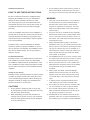
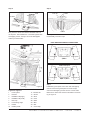
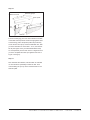
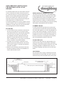
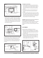
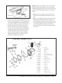
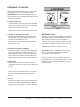
CENTURY
Round Pools
ASSEMBLY INSTRUCTIONS
ASSEMBLY INSTRUCTIONS
CENTURY -
ROUND
-
page
1
Installation Instructions
3.Do not attempt to lift the heavy boxes by yourself. To
HOW TO USE THESE INSTRUCTIONS
Be sure to read these instructions completely before
reduce the possibility of personal injury, have someone help you move heavy boxes (pool wall, liner, etc.).
beginning the installation of your pool. ATTENTION:
warning
Always use these assembly instructions to install
1.Your pool must be level within 2-3 cm all around.
your swimming pool. Ignore any English instructions
An unlevel pool may cause excessive stress on
included with the pool, as the size will be in inches, etc.
the pool frame. A pool which is not level may
ATTENTION: Check the pool parts with the English
cause a lot of pressure on the frame. This may
parts lists.
result in pool failure which could cause serious
personal injury.
These are installation instructions for the installation of
2.Your pool must be on undisturbed soil, preferably
several sizes of round pools. Use the pool parts list and
filtered sand. Filled up sand, sudden slopes within
extensive illustrations to identify your pool parts; then
15 cm or the water runoff may cause a cave in of
read these instructions and follow the steps that pertain
the subsoil. This could cause pool failure and may
to your pool assembly.
cause personal injury.
3.Always install the Warning Sign. The decal is
Embassy PoolCo. cannot be held liable for damage
designed to warn you, your friends and loved ones
caused by careless or improper installation. Your war-
that your pool is to be used for swimming and wad-
ranty is void if the pool assembly and installation instruc-
ing only. Do not allow any form of horseplay in or
tions are not followed exactly, or if the pool design is
around the pool. Failure to follow this warning can
altered in any way.
lead to severe personal injury. Read the “Safety
First” booklet (in English).
Contracted Installation
4.Use stabilised sand as a pool cove. Common sand
Embassy PoolCo. is not affiliated with any professional
can easily erode and allow the pool liner to rupture
pool installers and cannot assume any responsibility
which may cause pool failure or personal injury.
for installation mistakes made by the homeowner. If the
5.Secure your pool when not in use. Ladders and
pool is installed by others, please supervise the installa-
gates should be secured to reduce the possibility
tion and make sure that the correct installation method
of unauthorised entry and possible serious
is applied.
accidents.
6.Always repair liner leaks. Continued leakage
Change of pool design
between the pool wall and liner can cause wall
Embassy PoolCo. expressly reserves the right to change
damage to the wall which eventually may result
or modify the design and instruction during the course
in pool wall failure. This could result in personal
of our manufacturing procedures, without incurring any
obligation or liability to reapply such modifications on
products previously or currently sold.
injury.
7.To reduce the risk of possible electrical shock,
never install your pool under overhead wires.
8.Do not alter your pool as this may cause pool fail-
CAUTIONS
ure. Your warranty is void if the pool is altered.
1.Do not attempt to install pool wall on windy days.
9.Do not install a diving board, pool slide or any
An unsupported pool wall can easily blow down and
other recreational accessories for use during div-
may thus cause personal injury.
ing, sliding or jumping into your pool.
2.When assembling your pool, keep the parts not
10.ATTENTION: Do not install the pool liner at tem-
currently used in an area out of the way. Unpacked
peratures under 16ºC. At lower temperatures the
parts are easily tripped over and may be damaged
liner’s elasticity is too limited for proper installation.
or cause personal injury.
ASSEMBLY INSTRUCTIONS
CENTURY -
ROUND
-
page
POOL SIZES
Where to position my pool?
Before you start building your pool, pay attention to the
following points:
1.Garden fence.
2.Trees, roots, overhanging branches and falling
leaves.
Clearance radius
3,6 m round
3. Underground wiring or cables.
4.Position pool with regard to sun terrace or sunken 2,4 m
sitting area.
5.Position pool with regard to the sunshine.
6. Supervision of small children.
7. Convenient location of filter and pump.
8. Convenient electrical outlet for the pump
9.2 or 3 people for assistance during assembly.
10.Do not build in case of strong wind.
11. Walking space around your pool (60 cm).
12.Put your pool on a level underground.
13.In case of building the pool into the ground: Clearance radius
groundwater level.
4,6 m round
MATERIALS AND TOOLS NEEDED
(Not included)
2,9 m
Materials:
1. 12 nails, 4 cm long
2. Patio blocks, 1 per stud
3. Roller masonry or kite string
4. Binder clips
5.Straight board, 5 x 10 cm diameter
(Length, please refer to Step 1)
6. Scotch tape 5 cm wide
7. Wooden stake 5 x 5 cm, 50 cm long
8. Sub-liner
Clearance radius
5,5 m round
Tools:
1. Carpenter’s level
3,35 m
2. Carpenter’s saw
3. Fibre tip pen
4. Stanley knife
5. Star + regular screwdriver
6. Hammer
7. Shovel / barrow
8. Rake
9. Tape measure
ASSEMBLY INSTRUCTIONS
CENTURY -
ROUND
-
page
Step 1
Step 2
5x10 cm
Nail
Hole
Cleara
Centre
nce rad
5x5 cm
centre
ius
Bottom rail
Water level
30 cm
Patio block
end cap
Level
Use a wooden stake as the centre and make a circle of
the diameter of your pool. For this attach a wire or cord
on the one hand to the wooden stake and on the other
hand to a screw driver or marking pen. The size is half
Depending on the size of your pool (please refer to the
of the pool diameter starting from the wooden stake.
pool layout dimensions above) you will determine the
Create a circle with the bottom rails by sliding each
pool diameter and determine the outline of the working
bottom rail into a bottom rail connecting piece, with the
space (60 cm).
groove up according to the drawing. Attention, slide the
Drive the stake into ground at pool centre and draw a
rail up to the lips of the base plate. If the soil condition
circle around it. Now level and smooth the soil within
is not optimum, then place underneath each bottom rail
the circle as indicated. In order to obtain solid subsoil, it
connecting piece a concrete slab, countersunk to the
is better to remove and level the pool area and fill it up
bottom level for extra security.
with loose sand. Remove sods, stones, roots and other
objects that could puncture the liner. Remember that the
Lip
entire assembled pool framework must be level and be
Bottom end cap
on clean ground (preferably sifted sand).
Step 3
Bottom rail
Stabilizer rails
Pool wall
Step 4
cardboard
At this time remove the steel pool wall from the car-
Place the ends of the wall adjusters one on top of the
ton. Note the Up arrow. The starting point of the wall
other according to the drawing. If the ends do not fit one
assembly is dependent on the location where you have
on top of the other, correct then all studs somewhat, until
determined that the pump and filter will be located. The
the wall ends indeed fit one on top of the other. Attention,
skimmer and inlet openings are located at the end of the
the round form should be maintained. Connect the wall
coil. Always start in the centre of a bottom rail connecting
ends using the nuts and bolts which are in the box. Keep
piece, then each time uncoil 1.5 m and insert that into
the screw head on the inside of the pool. Remove the
the groove of the bottom rail. If both ends do not com-
burs from the screws. Place the protective strip using
pletely match up, correct that by sliding the bottom rail
tape.
more or less into the bottom connecting pieces.
ASSEMBLY INSTRUCTIONS
CENTURY -
ROUND
-
page
Step 5
Step 6
End cap
Stud
Holes
Screws
Screws
Now place the studs such that the threaded hole is at
the top front. The installation is connected together with
Carefully adhere to the details indicated in Figure A for
self tapping screws. A drop of oil on the self tappers
the assembly of the end caps.
makes your work easier.
HOLE DIAGRAM FORTHE COVER PANEL
Inside of the pool
Cover panel
3,60
Cover panel
m
Inside of the pool
Cover panel
4,60 / 5,50
m
Cover panel
Step 7
Figure A
Installation guard panel. Four each 3/8" self tapping
screws connect the guard panel to the end caps;
Legend for Figure A
screw the self tapping screws into the correct holes.
11 = Bottom rail
Mark with a marker the holes as indicated in the draw-
4 = Screws
17 = Screw
ing of Figure A.
5 = Stabilizer rail (large)
19 = Stud
1 = Cover panel
6 = Stabilizer rail (small)20 = Liner
7 = End cap28 = Wall
8 = Connecting angle29 = Bolt
9 = Guard
30 = Nut
10 = Plastic profile
31 = Cover strip
ASSEMBLY INSTRUCTIONS
CENTURY -
ROUND
-
page
ASSEMBLY OF THE GUARDS
Step 10
liner
side seam
water face
Step 8
Assemble the guards alongside the pool edge (guard
panels). Hook de guard starting from the outside of the
item number
bottom seam
Pool liner
pool alongside the edge; afterwards click it on the inside
towards the bottom.
Guard panel
End cap
Remove the wooden stake and recheck the soil if there is
gravel, glass or other sharp projections. Flatten foot prints
and other unevenness. As a soil cover and extra protection
of your pool lining, it is advisable to cover the soil with a
water resistant sub-liner that you can glue with adhesive
tape to the bottom side of the steel wall. Now place the
Stud
internal lining on the cover panel and check it according to
the instructions.
Step 9
NB: The relief face of the internal lining is the water face.
Cove
Step 11
30cm
Sand cove
Do not use soft sand
because then the
cove can crumble
away
Important step! On the inside of the steel wall, construct
Pool liner
a slanting elevation of stabilized sand of approx. 15 cm
high and wide with a mixing ratio of 1m3 fluvial sand
Work in both directions during the folding out of the liner
with 125 kg concrete). This is vitally important for the
and have the internal lining hang outside of the upper
preservation of the internal lining. It happens that due to
edge approximately 60 cm. The centre of the lining
the water pressure the liner underneath the bottom rail
should hang approximately 40 cm above the bottom.
is pressed outwards.
The bottom welding seam of the liner should be located
approximately 30 cm from the top (please refer to the
drawing).
ASSEMBLY INSTRUCTIONS
CENTURY -
ROUND
-
page
Step 12
Step 14
Water level
Garden hose
50cm
Clamp
Fill the pool up to approximately 50 cm below the cover
Before filling up the pool, place binder clips between the
panel. Make sure that during the filling the liner does not
studs. These binder clips are available from the builder’s
fall back into the pool. Water between the liner and the
merchant. Make sure that a piece of cardboard is placed
steel wall can cause damage to the earth cove (please
between the binder clip and the internal lining; this is to
refer to Step 9). First complete Steps 15, 16 and 17
protect the internal lining. The water pressure ensures in
before you continue filling.
principle that your pool liner is placed smooth and tight.
Check each time during filling that locally no excessive
tension takes place on the liner. The binder clips do not
unclamp themselves; that is why during too high tension they should be gradually adjusted and refastened.
Step 15
Disassemble 3 guards
Please note that a minimum tension is needed to make
your bottom smooth. If the water covers the bottom ± 5
cm, no creases or wrinkles should be located on the bottom; should this be the case despite everything, then pull
locally the top of the liner a bit, so that due to the water
pressure the crease disappears. Keep the liner at a minimum tension until the bottom has been filled with approx.
15 cm water and the liner is flush against the steel wall.
Step 13
CONTINUE FILLING THE POOL
With the aid of 2 or 3 people loosen the liner from 3
segments. Be careful and do not let the liner fall into the
water. While 1 man holds the liner, the other one disas-
After the pool is filled up, the bottom welding seam of
sembles from 3 segments the guards from the guard
the liner has to be located as a whole in the vicinity of
panels and end caps (please refer to the drawing).
the junction of the bottom wall. You do not have to worry
about the strength of the liner; the strength is calculated
at 1.5 x the original size. If the bottom seam is not situated in the correct location, it is possible that you will
not have sufficient liner to overhang outside the bottom
edge, so that you then have to start over rearranging the
liner.
ASSEMBLY INSTRUCTIONS
CENTURY -
ROUND
-
page
Step 16
Stabilizer rail large
Stabilizer rail small
Plastic profile
Pool liner
Pool
liner
Pool wall
Fold the overhanging part of the liner towards the outside
of the steel wall and pull the whole liner tight (please refer
to the drawing). Place the plastic profile strip all the way
across the liner and op top of that the stabilizer rails, after
you have slid those into each other ± 15 cm; then assemble all parts again which you had disassembled in Step
15 and repeat this process each time for 3 segments until
you have completed the whole pool (please also refer to
Figure A in Page 5).
Step 17
Now assemble the skimmer, inlet and filter as indicated
on the instruction specifically included for that. Then
continue filling the pool up to the indicated level on the
skimmer plate.
ASSEMBLY INSTRUCTIONS
CENTURY -
ROUND
-
page
SUPPLEMENTARY INSTRUCTIONS
FOR BUILDING A POOL IN THE
GROUND
To avoid that material rolls onto the site where the pool
is to be constructed, the location where the pool is to
INSTALLATION OF SKIMMER AND INLET
be constructed must be in the most elevated part of the
The skimmer and the inlet have to be installed before
garden. The surrounding landscape should be lower
the pool is filled with water and before the pool is filled
than the pool. Attention, the water level of the pool
up with stabilized sand. During the installation of the
should also be above the groundwater level during the
internal lining and the skimmer, the lead through for the
winter (water level 15 cm below the inlet).
skimmer may not be created yet. Install the inlet and
The specific installation such as seen in Figure 2 serves
gasket. Remove the internal lining from the inlet opening
only as a reference and is not representative for all pool
and install the valve delivered with the skimmer.
installations. The parts which may need special materi-
PLUMBER’S WORK
als are the lighting and chloride installations.
In order to prevent that the hoses move up and down,
EXCAVATING
you should connect the skimmer and the inlet with rigid
1. The circumference of the excavation is the same as
PVC to the filter (Figure 2). If you are using flexpipe, you
the size of the pool plus 60 cm around the whole
need to make sure that this pipe is not bent, before you
pool. Determine the size of the excavation pertaining
fill up the rest of the pool. Install the pump as closely as
to the size of the pool and use for this the exten-
possible to the pool in connection with the drawing in of
sive installation instruction delivered with the pool.
the pump. If this pump is a Doughboy Pool Powerpack,
(Attention, the soil should be at least 15 cm white
then you should place it below the water level.
sand or stabilized sand; on top of that we recommend
FILLING THE POOL
a layer of styrodur or a protective blanket.)
2. The depth of the excavation is dependent on the
First fill the pool with water up to approximately 5 cm
height of the pool and desired terrace. Use the size
away from the top edge. This procedure is absolutely
such as seen in Figure 1 to calculate how deep the
necessary to absorb the pressure performed on the wall
excavation should be.
during the application of stabilized sand. Ff the pool
3. After the pool is excavated, the frame and the wall
should be installed according to the installation ins-
is not filled completely with water, this can cause pool
failure.
truction delivered with the pool.
SHUTTERING
We recommend that you apply a shuttering around the
skimmer before the pool is filled up.A space around the
skimmer and any other accessories offer you the possiFigure 2
Specific installation
Cover panel
60 cm working space
around the pool
12-15 cm
Fill the pool up to 5 cm below the top edge
Grade
(2 cm per meter)
FIG. 1 - CONSTRUCTION PROVISIONS WHEN A POOL IS EXCAVATED
ASSEMBLY M
I NOSNTTRAUGCET II O
NN
SS
T RCUECNT TI E
U RCYE N
- TRUORUYN D
- P- A pGaI g
Ne
A 1
Feed towards pump
gate of filter
Check valve
(Recommended)
Space between the top of the pool
and stabilizer sand 22 cm
Retour towards
return gate
filter
Grade 2 cm per meter
Stabilisierter Sand
Füllen Sie erst das Schwimmbecken,
bevor Sie den stabilisierten Sand
auffüllen.
Valve
(Recommended)
PVC tube and fixtures
FIG. 2 SPECIFIC INSTALLATION
IMPORTANT MESSAGE:
bility to have easy access for maintenance or repairs.
ATTENTION: If the filling up takes place immediately
Piling up of loose material between the mixture and the
around the skimmer, it shall be more difficult in the futu-
poor wall may push in the wall. If extra material is placed
re to check the skimmer during leaks.
between the mixture and the cover material to get this at
the correct height, you should only use a sturdy mortar.
Doughboy is in no way liable for the expenses pertaining
to the finding and/or repairing of leaks, cutting, breaking
off and/or removing of stabilizing sand.
PREPARATION OF STABILIZER SAND
Mixing ratio 1 m3 fluvial sand with 125 kg concrete.
IMPORTANT WARNING:
Regardless the method used for the way the stabilized
sand is applied, you should pay close attention to the
wall of the pool during filling to be sure that the wall
does not collapse. If a dent occurs in the pool wall,
someone should enter the pool to push it back.
If this is not possible, you should lower the pressure to
the pool wall by removing the mixture
used to fill up the pool locally again so
Without patio blocks
With patio blocks
that the dent can be removed. Then
carefully fill up the pool again. You
should at all times pay attention to the
pool wall until the pool is completely
filled up. To prevent rust on the pool
wall, the water streaming out of the pool
should immediately be removed from the
pool wall. For this you should let the top
layer run off at least 2 cm such as can
Stabilized sand
be seen from the illustration. After the
mixture has been applied completely,
you should lower the water level to the
top line of the skimmer opening and cut
Keep the stabilized sand 5 cm below
the screw of the guard
Top of the
patio block
Stabilized sand
Keep the patio blocks 5 cm below
the screw of the guard
away the liner in the skimmer opening.
FIG.3 - WITH/WITOUT PATIO BLOCKS
ASSEMBLY IN
M SOTNRTUA CG TEI OI N
NS
S TC
R EU NC TT UI ER YC E
- NRTOUURNYD - - P pA aGgI N
e A1 0
1
Standard SKIMMER
Fig. 1
Standard Skimmer
MODELS 5-2091-015
INSTALLATION INSTRUCTIONS
Cover
Outside pool
Inlet
Sand filter
Pool pump
PREPARATION OF THE POOL
The pool should be built up the correct way based
on the pool assembly and installation instructions.
Approximately 70 cm water should press against the
metal wall, so that there isn’t any elasticity anymore
against the liner, before the skimmer is installed.
ATTENTION: After the skimmer hole is cut open the liner
can no longer be moved.
Your standard skimmer facilitates the maintenance of
your pool. Leaves and floating refuse are taken out of
Skimmer installation
the water and enter into the skimmer basket. Clean the
1. Remove all parts from the carton box. Remove the
basket regularly to continuously keep your pool clean
cover of the skimmer by sliding it to the front and
and hygienic. The numbers indicated between the brac-
then lifting is; remove the skimmer basket.
kets refer to the numbers of the illustration (Fig 7).
2. Fasten the skimmer valve (7) to the skimmer (3)
by using three screws (8). Push the skimmer valve
into the skimmer so that the foam side is facing the
bottom.
3. Install the top skimmer gasket (9) into the square
opening of the metal wall; make sure that the gasket is positioned properly in front of the holes. Then
Needed tools
fasten the bottom gasket (10) into the vacuum con-
• Crosshead screwdriver
nection. Place the skimmer plate on the inside of
• Screwdriver
the pool, and keep the skimmer on the outside of
• Stanley knife
the pool. First screw tight the top angles with two
self tapping screws. Press the self tapping screws
through the skimmer plate and press the liner into
the openings of the skimmer. Lightly tighten the self
tapping screws.
ASSEMBLY IN
M SO TNRT UA C
G TE I OI N
N SS T C
RE
UN
C TT U
I ER YC E- NRTOUURNY D - - P p
A aG gI N
e A1 1
Installation inlet fixture
Fig. 2
1. Install the gasket of the inlet (17) into the wall opening. Insert the inlet fixture (18) through the liner and
Inside pool
Skimmer
plate
the wall starting from the inside of the pool. Make a
small notch into the liner and press the inlet fixture
through.
2. Now screw the inlet (16) onto the inlet fixture; turn
it clockwise until the inlet end points towards the
Skimmer
valve
Suction connection for
cleaning pool
bottom.
3. Install the eyeball inserted piece (20) into the eyeball
(21). Insert the eyeball with the inserted piece into the
inlet fixture, turn the closure (22) on top of that; make
sure that the eyeball location stands in the water run-
4. Screw the rest of the self tapping screws through the
ning off direction of the skimmer opening
skimmer plate, liner, gaskets, wall and the corresponding openings in the skimmer. Tighten all self tapping
screws manually; this to prevent damage to the skim-
WARNING: Always keep the water level between the
mer plate. With a Stanley knife now cut away the liner
water level signs on the skimmer plate.
on the inside of the skimmer plate; do the same with
After installation of the skimmer check if there are leaks
the vacuum inlet. (Fig 4)
when the pool is filled. Continuous leaks can cause
damage to the pool wall, so that eventually there is pool
failure.
Fig. 3
Self tapping
screw
Skimmer plate
Gasket
VACUUMING
Empty the skimmer basket before suctioning.
1. Switch off the pump. Assemble the vacuum nozzle,
handle and hose. A proper flexible hose provides the
best suction results. Attach the free end to the vacuum adaptor (13).
Gasket
2. Switch on the pump. Keep the free end of the hose
Inside pool wall & liner
against the outlet of the inlet fixture. Because of this
air shall pass through the hose. When bubbles no
ATTENTION: The gasket around the vacuum connection
longer exit from the vacuum nozzle, all air has been
(10) is necessary to ensure a watertight closure around
removed (please refer to Figure 5/6).
the vacuum connection during the suctioning off of
water. Attach the suction cover (12) and the attachment
of the suction cover (11) to the skimmer plate with a
screw (8).
Fig. 4
Cutting away
liner
Skimmer
opening
Suction connection
Outside pool
Fig. 5
Fig. 6
ASSEMBLY IN
M SOTNRTUA CG TEI OI N
NS
S TC
R EU NC TT UI ER YC E
- NRTOUURNYD - - P pA aGgI N
e A1 2
1
Warning: Never try to install the cover in a suctioning
Lid
position if the pump is switched on. The cover might
Vacuum
adaptor
suddenly be pulled down due to the strong suction of the
pump. You may suffer personal injury to your hands or
fingers.
5. When the cover is in place, you can switch on the
Suction cover
Fig. 7
pump and put into operation the suction of the pool
floor.
6. When you are finished suctioning, you have to switch
3. Fold the cover of the vacuum opening (12) so that
off the pump. Remove the vacuum hose with the
it points towards the bottom. Insert the tapering end
vacuum adaptor connected to it from the pool. Clean
of the vacuum adaptor with the hose attached into
the skimmer basket and your filter. Relocate the cover
the opening by making a turning movement (Fig. 7).
to the original position on the top of the skimmer.
4. The cover (2) has two functions. In the normal
position is covers the top of the filter. During suc-
Switch on the pump to resume the normal operation
of the pump.
tion, this same cover becomes the closing plate for
suctioning; make sure that the pump is in the OFF
position. Remove the cover, turn it 90º and let it
drop to the inside and place it above the basket.
Make sure that there is no air under the cover.
Trapped air shall make the cover rise.
STANDARD SKIMMER PARTS
No. Article
Amt Description
1 1300-1002
1
Skimmer basket
2 1121-1506
1
Skimmer cover
3 1121-1864
1
Skimmer
4 360-1794
1
Sticker
5 1121-1358
1
Skimmer valve
6 340-1600
1
Attachment skimmer valve
7 1107-1275
1
Skimmer valve plus attachment
8 330-1008
4
Screws
9 307-1029
1
Top of gasket
10 307-1030
1
Bottom of gasket
11 340-2089
1
Attachment suction cover
12 348-1028
1
Suction cover
13 340-1590
1
Water suction adaptor
14 330-1004
15
Screws
15 340-2090
1
Skimmer plate
16 340-1591
1
Inlet
17 307-1031
1Gasket inlet
18 340-1592
1
Inlet adaptor
19 340-1594
1
Closure disk
20 340-1595
1
Eyeball attachment
21 348-1027
1
Eyeball
22 340-1593
1
Closure for the inlet
23 360-2023
1
Operating Instructions Label
ASSEMBLY IN
M SOTNRTUA CG TEI OI N
NS
S TC
R EU NC TT UI ER YC E
- NRTOUURNYD - - P pA aGgI N
e A1 3
1
PREPARING FOR WINTER
When the swimming season is over, you have to follow
the instructions to get your pool ready for winter.
ATTENTION! Do not remove all the water from your
pool and also do not remove the liner. An empty pool can
namely cause pool failure.
Lower the water level
- Lower the water level in your pool so that it is approximately 6” (15 cm) below the inlet fixture; maintain this
water level by checking it regularly.
- If you have a skimmer, then absolutely do not let the
water freeze in the skimmer but rather drain this water.
Check all screws and connections
Anti-freeze liquid
- Make sure that all installation connections and parts
This liquid can be used without problems in combination
are positioned correctly and that the pool wall is not
with chloride products. Upon finding algae present first
moved away from the bottom rails.
apply a ‘shock treatment.’ The liquid should be, dis-
- Make also sure that all connections are water tight.
Check if there is rust
solved in a pail of water, spread out equally across the
water surface. During the dosage the pump should be
- Correct all damages or rust spots with a varnish stick.
in operation. The dosage is 0.5 litres per 10 m3, after
approximately four weeks 0.3 litres per 10 m3.
Check the liner (interior tarpaulin)
- Make sure that the top of the liner is still overhanging
ATTENTION! Never mix the liquid with other pool che-
the pool wall attached to the plastic edge. Do not
micals or chemicals and always add the product to
remove the liner from your pool. Upon removal of the
water, never the other way around.
liner of the pool the warrantee becomes void. Do not
pump dry all the water from the pool during the winter.
If you do not adhere closely to the winter instructions,
the warrantee of your pool may become void. Thus care-
Leaks found
fully adhere to all instructions for maintaining your pool
- Make sure that there aren’t any leaks in the liner.
during the winter.
Leaks during the winter can cause serious damages to
your pool.
Pool accessories
- Remove all pool accessories from the pool, including
the ladder. Leave the skimmer and inlet fixture in
place.
The filter
- Disconnect the filter from your pool and follow the filter
instructions for maintaining the filter during the winter.
Clean the pump and the filter for the winter (frost free).
ASSEMBLY IN
M SOTNRTUA CG TEI OI N
NS
S TC
R EU NC TT UI ER YC E
- NRTOUURNYD - - P pA aGgI N
e A1 4
1