1
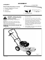
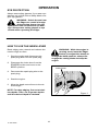
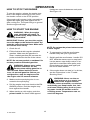
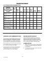
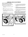
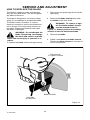
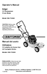
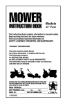
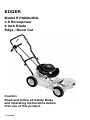
EDGER
Model EV3850x4NA
3.8 Horsepower
9 Inch Blade
Edge / Bevel Cut
Caution:
Read and follow all Safety Rules
and Operating Instructions before
first use of this product.
F–041105C
TABLE OF CONTENTS
WARRANTY STATEMENT . . . . . .
SAFETY RULES . . . . . . . . . . . . . . .
INTERNATIONAL SYMBOLS . . . .
ASSEMBLY . . . . . . . . . . . . . . . . . . .
2
3
5
6
OPERATION . . . . . . . . . . . . . . . . . .
MAINTENANCE . . . . . . . . . . . . . . .
TROUBLE SHOOTING CHART . .
REPAIR PARTS . . . . . . . . . . . . . . .
WARRANTY STATEMENT
LIMITED TWO–YEAR WARRANTY ON EDGER
For two years from the date of purchase, when this Edger is maintained, lubricated, and
tuned up according to the operating and maintenance instructions in the owner’s manual,
Murray will repair, free of charge, any defect in material or workmanship.
If this Edger is used for commercial or rental purposes, this warranty applies for only 90 days
from the date of purchase.
This warranty does not cover the following:
S Expendable items which become worn during normal use, such as spark plugs, etc.
S Repairs necessary because of operator abuse or negligence, including bent crank shafts
and the failure to maintain the equipment according to the instructions contained in the
owner’s manual.
WARRANTY SERVICE IS AVAILABLE BY RETURNING THE Edger TO THE NEAREST
AUTHORIZED SERVICE CENTER IN THE UNITED STATES. THIS WARRANTY APPLIES ONLY WHILE THIS PRODUCT IS IN USE IN THE UNITED STATES.
This Murray, Inc. Limited Warranty gives you specific legal rights, and you may also have
other rights which vary from state to state. This Limited Warranty is given in lieu of all
other expressed and implied warranties including the implied warranty of merchantability and warranty of fitness for a particular purpose. If you need additional information on this written warranty or assistance in obtaining service, write or call: MURRAY, INC.
Customer Service Department, P.O. Box 268, Brentwood, Tennessee
37027,
1–800–251–8007
Engine Exhaust, some of its constituents, and
certain vehicle components contain or emit
chemicals known to the State of California to
cause cancer and birth defects or other reproductive harm.
Battery posts, terminals and related accessories contain lead and lead compounds, chemicals known to the State of California to cause
cancer and birth defects or other reproductive
harm. WASH HANDS AFTER HANDLING.
F–041105C
2
9
14
18
19
SAFETY RULES
Safe Operation Practices for Edger.
WARNING: Look for this symbol to point out important safety precautions.
It means: “Attention! Become Alert! Your Safety Is Involved.”
Operating Safety
WARNING: To prevent accidental starting when setting–up,
transporting, adjusting or making repairs, always disconnect spark
plug wire and put wire where it cannot
contact the spark plug .
S Never allow children or young teenagers to
operate the Edger. Keep them away while
it is operating. Never allow adults to operate the Edger without proper instruction.
S Do not operate this machine if you are taking drugs or other medication which can
cause drowsiness or affect your ability to
operate this machine.
Before Use
S Do not use this machine if you are mentally
or physically unable to operate this machine safely.
S Read the owner’s manual carefully. Be
thoroughly familiar with the controls and
the proper use of the Edger. Know how to
stop the Edger and disengage the controls
quickly.
S Always wear safety glasses or eye shields
during operation or while performing an
adjustment or repair to protect your eyes
from foreign objects that may be thrown
from the Edger.
S Do not operate the Edger without wearing
adequate outer garments. Wear footwear
that will improve footing on slippery surfaces.
S Do not put hands or feet near or under rotating parts.
S Keep the area of operation clear of all persons, particularly small children and pets.
S Exercise extreme caution when operating
on or crossing gravel drives, walks, or
roads. Stay alert for hidden hazards or
traffic.
S Thoroughly inspect the area where the
Edger is to be used and remove all foreign
objects.
S Exercise caution to avoid slipping or falling.
Fuel Safety
S Never operate the Edger without proper
guards, plates, or other safety protective
devices in place.
S Handle fuel with care; it is highly flammable.
S Never operate the Edger at high transport
speeds on slippery surfaces. Look behind
and use care when backing.
S Use an approved container.
S Never allow bystanders near the
Edger.
S Check fuel supply before each use, allowing space for expansion as the heat of the
engine and/or sun can cause fuel to expand.
S Keep children and pets away while
operating.
S Never operate the Edger without good visibility or light.
S Fill fuel tank outdoors with extreme care.
Never fill fuel tank indoors. Replace fuel
tank cap securely and wipe up spilled fuel.
S Do not run the engine indoors. The exhaust fumes are dangerous, containing
CARBON MONOXIDE, an ODORLESS
and DEADLY GAS.
S Never remove the fuel tank cap or add fuel
to a running or hot engine.
S Never store fuel or Edger with fuel in the
tank inside a building where fumes may
reach an open flame.
F–041105C
S Take all possible precautions when leaving
the Edger unattended. Stop the engine.
3
S Do not overload the Edger capacity by attempting to till too deep at too fast a rate.
Safe Storage
SAFETY RULES
spect the Edger for any damage, and repair the damage before restarting and
operating it.
S Always refer to the owner’s manual instructions for important details if the Edger is to
be stored for an extended period.
S If Edger should start to vibrate abnormally,
stop engine and check immediately for the
cause. Vibration is generally a warning of
trouble.
S Never store the Edger with fuel in the fuel
tank inside a building where ignition
sources are present such as water and
space heaters, clothes dryers, and the like.
Allow the engine to cool before storing in
any enclosure.
S Stop the engine whenever you leave the
operating position. Also, disconnect the
spark plug wire before unclogging the
blade and when making any repairs, adjustments, or inspections.
S Keep the Edger in safe working condition.
Check all fasteners at frequent intervals for
proper tightness.
Repair / Adjustments Safety
S When cleaning, repairing, or inspecting,
shut off the engine and make certain all
moving parts have stopped.
S After striking a foreign object, stop the engine. Remove the wire from the spark plug,
and keep the wire away from the plug to
prevent accidental starting. Thoroughly in-
S Never attempt to make any adjustments
while the engine is running except when
specifically recommended by the manufacturer.
F–041105C
4
SAFETY RULES
INTERNATIONAL SYMBOLS
IMPORTANT: Many of the following symbols are located on your unit or on literature supplied with the product. Before you operate the unit, learn and understand the purpose for
each symbol.
Control And Operating Symbols
Slow
Fast
Fuel
Oil
WARNING
Rotating Parts. Stop Engine.
Disconnect Spark Wire Before
Making Adjustments.
WARNING
Safety Warning Symbols
WARNING
Thrown Objects.
Keep Bystanders Away.
IMPORTANT
Read Owner’s Manual
Before Operating
This Machine.
F–041105C
WARNING
Wear Eye Protection
5
STOP
ASSEMBLY
ASSEMBLY
1 – Control Rod
Parts Packed Separately In Carton
1 – Owner’s Manual (not shown)
1 – Container Of Oil
2 – Hair Pin
1 – Control Rod
1 – Hair Pin
1 – Container of Oil
from the carton.
WARNING: Always wear safety
glasses or eye shields while assembling the Edger.
2. Cut down all four corners of the carton.
3. Remove the packing material positioned
around the front and rear of the unit.
Leave the packing material on the bottom of the unit until the control rod is assembled. This will keep the front wheel
in a stable position.
Figure 1 shows the Edger completely assembled.
References to the right or left side of the
Edger are from the viewpoint of the operator’s position behind the unit.
REMOVE THE EDGER FROM THE
CARTON
4. Lift the Edger out of the carton and place
on a hard level surface.
1. Remove the bottle of oil and parts bag
Figure 1
F–041105C
6
ASSEMBLY
HOW TO RAISE THE HANDLE
1. Loosen the knobs and raise the upper
handle to the upright position. See
Figure 2.
5. Insert the other end of the control rod,
from RIGHT to LEFT, through the hole in
the depth control lever and fasten with
hair pin. See Figure 4.
2. Tighten the knobs. Make sure the
knobs are to the outside of the handles
as shown in Figure 2.
6. Move the depth control lever forward to
the STARTING and TRANSPORT position.
3. Insert the end of the control rod, from
RIGHT to LEFT, through the hole in the
front wheel arm. Attach with hair pin
found in parts bag. See Figure 3.
7. Remove any packing material from the
bottom of the unit.
8. To attach the recoil starter rope to the
rope guide, twist the recoil starter rope
through the rope guide. See Figure 5.
4. Push down on the handle to tilt the unit
back.
Knobs
Upper
Handle
Hairpin
Depth Control
Lever
Control
Rod
Control Rod
Figure 4
Figure 2
Front
Wheel Arm
Hair Pin
Rope Guide
Control
Rod
Recoil Starter
Rope
Figure 3
F–041105C
7
Figure 5
ASSEMBLY
HOW TO PREPARE THE ENGINE
ENGINE DOES NOT CONTAIN
OIL OR GASOLINE
See the engine manufacturer’s instructions
for the type of gasoline and oil to use. Before
you use the unit, read the information on
safety, operation, maintenance, and storage.
This Edger was shipped with a 20 ounce
container of SAE30 motor oil. Add this oil to
the engine before operating. To fill the crankcase, remove the oil fill cap/dipstick and add
the SAE30 motor oil. DO NOT OVERFILL.
NOTE: The engine may contain a small
amount of oil. When adding oil, frequently
insert the oil fill cap/dipstick and check
the amount of oil in the engine. DO NOT
OVERFILL.
WARNING: Follow the engine
manufacturer’s instructions for
the type of gasoline and oil to
use. Always use a safety gasoline container. Do not smoke when adding gasoline to the engine. When inside an enclosure, do not fill with gasoline. Before
you add gasoline, stop the engine. Let
the engine cool for several minutes.
n
IMPORTANT: This unit is equipped with an
internal combustion engine and must not
be used on or near any unimproved forest–
covered, brush–covered or grass–covered
land unless the engine’s exhaust system is
equipped with a spark arrester meeting applicable local or state laws (if any). If a
spark arrester is used, it must be maintained in effective working order by the operator.
In the State of California the above is required by law (Section 4442 of the California Public Resources Code). Other states
may have similar laws. Federal laws apply
on federal lands. See an Authorized Service Center for a spark arrester for the muffler.
CHECKLIST
As you learn how to use the Edger, pay extra
attention to the following important items:
For the best performance and satisfaction
from this quality product, please review the
following checklist before you operate the
Edger:
n
All assembly instructions have been
completed.
n
Check carton. Make sure no loose
parts remain in the carton.
n
All fasteners have been properly tightened.
F–041105C
8
nn
Engine oil is at proper level.
nn
Fuel tank is filled with a fresh, clean,
regular Unleaded gasoline.
nn
Become familiar and understand the
function of all controls. Before your
start the engine, operate all controls.
OPERATION
KNOW YOUR EDGER
READ THE OWNER’S MANUAL AND ALL SAFETY RULES BEFORE YOU OPERATE the
Edger. To familiarize yourself with the location of the controls, compare the illustrations with
your Edger. Save this manual for future reference.
Engine Stop
Lever
Depth Control Lever
Throttle Control
Primer Button
Air Filter
Control Rod
Recoil
Starter
Handle
Fuel Tank
Cap
Oil Fill Cap
Blade Guard
Index Lever
(Located On Left
Side Of Edger)
Blade
Blade Guide
Figure 6
Throttle Control – The engine is set to
run at full speed. The throttle control has
only two positions, RUN and STOP.
Primer Button – Injects fuel directly into
the carburetor for faster starts.
Recoil Starter Handle – The engine is
equipped with an easy pull recoil starter.
Index Lever – Set bevel cut.
F–041105C
Depth Control Lever – Controls depth of
cut.
Blade Guard – Use to prevent stones and
debris from being thrown at the operator.
Engine Stop Lever – Must be engaged
9
to allow the engine to start and run. Release
to stop the engine.
EYE PROTECTION
OPERATION
Always wear safety glasses. If you wear eye
glasses, put a Wide Vision Safety Mask over
your eye glasses.
WARNING: Debris thrown from
the Edger can result in foreign
objects being thrown into the
eyes, which can cause severe eye damage. Always wear safety glasses or eye
shields when operating the Edger.
HOW TO USE THE INDEX LEVER
Bevel edging cuts a trench and reduces the
need to edge as often.
WARNING: While the engine is
running, never leave the Edger.
Before you adjust the wheels or
change the blade position, always disengage the cutting blade and stop the
engine.
1. Stop the engine and disconnect the
spark plug wire from the spark plug.
2. Disengage the index lever from the
EDGING position and move to the
BEVEL position.
Index Lever
3. Reconnect the spark plug wire to the
spark plug.
4. Start the engine.
5. Move the depth control lever to the desired height.
NOTE: For deep edging, first cut at shallow depths. Then, cut at greater depths
until the desired depth is obtained.
F–041105C
Figure 7
10
OPERATION
HOW TO USE
THE DEPTH CONTROL LEVER
WARNING: When the engine
runs, the blade will rotate. To
prevent injury, keep hands and
feet away from blade.
1. Start the engine.
HOW TO STOP THE EDGER
2. To lower the cutting blade, pull the depth
control lever back.
1. Move the depth control lever forward to
raise the blade. Then, release the engine
stop lever. See Figure 8.
3. Select the edging depth that you need.
There are three selections with an
approximately depth of two inches.
NOTE: For deep edging, first cut at shallow depths. Then, cut at greater depths
until the desired depth is obtained.
WARNING: Never leave the
Edger unattended while the engine is running. Always raise
the cutting blade and stop the engine.
Engine Stop Lever
(Operating Position)
HOW TO USE
THE ENGINE STOP LEVER
1. Release the engine stop lever and the
engine and the blade will automatically
stop. To run the engine, hold the engine
stop lever in the operating position. See
Figure 8.
2. If the engine continues to run, move the
throttle control to the STOP position (see
Figure 9).
Depth
Control
Lever
IMPORTANT: Before you start the engine,
operate the engine stop lever several
times. Make sure the engine stop cable
moves freely. If the engine stop cable is
bent or damaged, replace the cable. If the
problem continues, take the Edger to an
Authorized Service Center to correct the
problem.
Figure 8
HOW TO USE
THE PRIMER BUTTON
ing, the throttle control must be in the
RUN position. (see Figure 9).
When starting a cold engine, push the primer button five times (see Figure 9). Wait
approximately two seconds between each
push.
IMPORTANT: When starting a warm engine, do not use the primer button.
HOW TO USE
THE THROTTLE CONTROL
1. The engine is designed to operate at full
speed. The throttle control has only two
positions, RUN and STOP. When operatF–041105C
Throttle
Control
Primer
Button
11
Figure 9
OPERATION
HOW TO STOP THE ENGINE
mately two seconds between each push.
See Figure 10.
To stop the engine, release the engine stop
lever. If the engine continues to run, move
the throttle control to the STOP position.
If the engine will not stop, hold a screwdriver
against the spark plug and against the engine cooling fins. The spark will go to ground
and the engine will stop.
HOW TO START THE ENGINE
WARNING: When the engine
runs, the blade will rotate. To
prevent injury, keep hands and
feet away from blade.
Throttle
Control
Primer
Button
IMPORTANT: Before you start the engine,
move the edger to the desired location. Operate the controls several timer. Make sure
all controls move freely.
NOTE: Do not use the primer button to start
a warm engine.
1. Check the oil.
2. Fill the fuel tank with regular unleaded
gasoline. Make sure the gasoline is
clean. Leaded gasoline will increase deposits and shorten the life of the valves.
6. To start engine, hold the recoil starter
handle firmly with your right hand.
7. Quickly pull the recoil starter handle. DO
NOT allow the starter rope to snap back.
Let the starter rope slowly rewind. If engine fails to start after three pulls, push
primer button two times and again pull
the recoil starter handle.
NOTE: Do not use gasohol or methanol. Do
not use premium unleaded gasoline.
WARNING: Always use a safety
gasoline container. Do not
smoke when adding gasoline to
the fuel tank. When inside an enclosure, do not add gasoline. Before you
add gasoline, stop the engine and let
the engine cool for several minutes.
8. If the engine does not start in 5 or 6 tries,
see the instructions in the “Trouble
Shooting Chart”.
WARNING: Never run the engine indoors or in a poorly ventilated area. Engine exhaust
contains carbon monoxide, an odorless
and deadly gas. Keep hands, feet, hair
and loose clothing away from any moving parts. Avoid the muffler and surrounding areas. Temperatures can exceed 150 degrees.
3. Make sure the spark plug wire is connected to the spark plug.
4. Pull the engine stop lever back to the ENGAGED position. Hold the engine stop
lever against the handle.
5. When starting a cold engine, push the
primer button five times. Wait approxi-
F–041105C
Figure 10
12
EDGING TIPS
OPERATION
S Edging is best performed when conditions
are dry. If the soil is to wet, dirt becomes
packed around the blade causing premature belt wear and decreased performance.
S If dirt does become packed around the
blade, stop the engine and remove the
wire from the spark plug. Remove the
packed dirt and debris from the blade.
S For deep edging, first cut at shallow
depths. Then, cut at greater depths until
the desired depth is obtained.
S For uniform edging, make sure the blade
guide rides on the surface.
S Edging can be customized by varying the
number of passes and by the distance the
blade is from the surface.
WARNING: Read the Owner’s
manual. Know location and
functions of all controls. Keep
all safety devices and shields in place.
Never allow children or uninstructed
adults to operate Edger. Shut off engine
before unclogging blade or making repairs. Keep bystanders away from machine. Keep away from the blade all rotating parts, which cause injury.
F–041105C
13
MAINTENANCE
CUSTOMER RESPONSIBILITIES
SERVICE
RECORDS
Fill in dates as you
complete regular
service.
After
First
2
Hours
Before
Each
Use
Often
Lubricate All Pivot
Points
Before
Each
Season
Before
Storage
SERVICE
DATES
√
√
Check Engine Oil
Level
√
√
√
Check Spark Plug
√
√
Check Drive Belt
√
Check Blade For
Wear Or Damage
√
√
GENERAL RECOMMENDATIONS
ENGINE MAINTENANCE
Use the following maintenance section to
keep your unit in good operating condition.
All the maintenance information for the engine is in the “Engine Instruction Book”. Before you start the engine, read this book.
The warranty on this Edger does not cover
items that have been subjected to operator
abuse or negligence. To receive full value
from the warranty, the operator must maintain the Edger as instructed in this manual.
LUBRICATION
Some adjustments must be made periodically to properly maintain your Edger.
1. After each 25 hours, apply a small amount
of engine oil to all moving parts, particularly the wheels.
All adjustments in the Service and Adjustments section of this manual must be
checked at least once each season.
F–041105C
Every
25
Hours
√
Lubricate Wheel
Axles
Tighten All Fasteners
Every
10
Hours
2. To lubricate the engine, refer to the “Engine Instruction Book”.
14
SERVICE AND ADJUSTMENT
HOW TO REMOVE THE BELT
5. To compress the spring and release tension on the belt, push the blade bearing
housing back toward the engine (see
Figure 12).
The belt made of a special compound. If the
belt becomes worn or breaks, replace the
belt with an original equipment belt.
1. Disconnect the spark plug wire from the
spark plug.
6. Carefully note the twist of the belt around
the engine pulley. Remove the old belt.
Replace with an original equipment belt.
2. Drain the gasoline and oil from the engine.
7. To install a new belt, reverse the above
steps. Make sure to twist the new belt as
shown in Figure 12.
3. Tip the Edger backwards on the handle.
Block the top of the handle against a wall
or under a bench.
NOTE: If the belt is not installed properly,
the blade will not turn in the proper direction and can damage the blade or belt.
4. Remove the screws from the belt guard
(see Figure 11).
Belt
Engine Pulley
Blade Housing Bearing
Spring
Note Direction
Of Twist
Screw
Belt Guard
F–041105C
Figure 12
Screw
Figure 11
15
SERVICE AND ADJUSTMENT
HOW TO REPLACE THE BLADE
The blade is subject to wear and damage,
such as nicks and dents. This will not generally affect its function.
1. Disconnect the spark plug wire from the
spark plug.
The blade is designed to not require sharpening. Do not attempt to sharpen the blade.
The blade is also reversible. If nicks or
dents are excessive, remove the blade and
turn it around. This will provide a fresh cutting edge. Replace the blade if both sides
are worn or damaged.
2. Remove the blade locknut that holds
the blade to the drive shaft.
WARNING: To remove or tighten the blade locknut, always
use the method shown in
Figure 13. Always position the holding
wrench on the nut behind the blade.
WARNING: Do not sharpen the
blade. Sharpening can damage
the blade and cause it to break,
which can cause injury to yourself or to
others.
3. Remove the blade.
4. Install a new blade and blade locknut.
Tighten the blade locknut to a torque of
40–45 foot pounds.
To replace the blade, follow the steps below.
Turn Wrench
To Tighten Locknut
Blade Locknut
Hold Nut,
Do Not Turn
Figure 13
F–041105C
16
STORAGE
SERVICE AND ADJUSTMENT
der. Slowly pull the recoil–start grip so
that the oil will protect the cylinder. Install
a new spark plug in the cylinder.
WARNING: Never store the
Edger indoors with fuel in the
fuel tank. Never store in an enclosed, poorly ventilated area where
fumes could reach an open flame, a
spark or a pilot light as on a furnace, water heater or clothes dryer.
5. Clean the dirt and debris from the cylinder cooling fins and the engine housing.
6. Completely clean the Edger.
7. Check the Edger for worn or damaged
parts. Tighten all loose hardware.
WARNING: Do not remove gasoline while inside a building,
near a fire, or while you smoke.
Gasoline fumes can cause an explosion
or a fire.
8. Apply a small amount of engine oil to all
moving parts, particularly the wheels.
9. Put the unit in a building that has good
ventilation.
When the Edger is put in storage for thirty
days or more, follow the steps below to
make sure the Edger is in good condition the
following season.
10. Cover the Edger with a suitable protective cover that does not retain moisture.
Do not use plastic.
1. Drain the fuel tank.
IMPORTANT: Never cover the Edger while
the engine and exhaust areas are still
warm.
2. Let the engine run until it is out of gasoline.
NOTE: A yearly checkup or tune–up by
an Authorized Service Center is a good
way to make sure that your Edger will
provide maximum performance for the
next season.
3. Drain the oil from the warm engine. Fill
the engine crankcase with new oil.
4. Remove the spark plug from the cylinder. Pour one ounce of oil into the cylin-
F–041105C
17
TROUBLE SHOOTING CHART
TROUBLE
CAUSE
CORRECTION
Engine difficult to start
Stale fuel
Drain fuel tank. Fill with fresh
fuel.
Clogged fuel filter
Replace fuel filter
Dirt in fuel tank or out of fuel
Clean fuel tank.
Carburetor out of adjustment
See Carburetor Adjustment
section.
Fouled spark plug
Clean and set spark plug
gap.
Dirty air filter
Replace air filter.
Plugged air filter
Replace air filter.
Debris interfering with blade
Clean debris from blade.
Loose blade
Tighten blade nut.
Defective V–belt
Replace V–belt.
Defective quill bearings
Replace the quill assembly.
Damage or worn blade
Reverse the blade or replace
the blade.
Loose parts
Stop engine immediately.
Tighten all fasteners. If
vibration continues, take the
unit to an Authorized Service
Center.
or
Engine runs erratically
or
Engine will not run at full
speed
Engine smokes
excessively
Cutting blade will not
rotate
Blade will not cut properly
Excessive vibration
F–041105C
18
MODEL EV3850x4NA
10
100
321
317
318
20
334
332
302
22
301
311
310
12
21
321
316
315
328
314
305
300
320
313
321
343714C
KEY
NO. DESCRIPTION
PART NO.
KEY
NO. DESCRIPTION
PART NO.
10
12
20
21
22
100
300
301
302
305
310
311
313
–––––
25x6
52052
338490
120580
740124E245
740096E701
51603
412281
32668
331076E245
2x53
15x88
314
315
316
317
318
320
321
328
332
334
––
––
––
22265
740297
46023
338582
337792E245
336631
26x245
740086
783641
36368
333874
710421
F–041105C
Engine
Screw
Pulley, V3L
Key, Hi Pro #505
Screw, Set
Frame, Edger
Quill Assembly
Spring
Spring Pin
Belt, V4L
Blade Guard
Bolt, Carriage
Nut, 5/16–18
F–041105C
19
Flat washer
Blade, Edger
Nut, 1/2–20
Deflector, Rubber
Plate, Rubber Flap
Belt Guard
Screw, 10–16x.50
Lever, Blade
Washer
Pin, Hair
Decal, Blade Cover
Decal, Bevel/Edge
Instruction Manual
MODEL EV3850x4NA
418
412
416
419 422
417
420
423
405
409
421
411
427
406
423
408
407
415
410
428
425
424
426
403
423
428
427
REF.
FRONT WHEEL ARM
402
REF.
FRAME ASSY.
REF.
ENGINE WIRE
401
343712C
F–041105C
20
MODEL EV3850x4NA
F–041105C
KEY
NO.
DESCRIPTION
PART NO.
401
Bolt, 5/16–18x.75
711558
402
Nut, 5/16–18
15x79
403
Lower Handle
740128E701
405
Handle, Depth
740130E701
406
Screw
180081
407
Spring, Compression
25644
408
Nut, 5/16–18
1498
409
Brkt, Adj. Quadrant
740143E701
410
Rope Guide
672510
411
Screw, 1/4–20x1.25
180024
412
Nut, 1/4–20
782585
415
Upper Handle
740142E701
416
Bail, Operator Control
337744
417
Torsion Spring
337775
418
Nut, Push On
314276
419
Cap, Operator Control
339489
420
Insulator, Oper Control
339229
421
Screw, #6x.50
57796
422
Clip, Grounding
340162
423
Cable Tie
71372
424
Bolt, 5/16–18x.75
315288
425
Wing Knob 5/16–18
71294
426
Rod, Control
740144E701
427
Hair Pin
36368
428
Washer
138485
––
Decal, Engine Control
402862
––
Decal, Blade Height
402859
––
Decal, Danger Info.
48x968
21
MODEL EV3850x4NA
116
118
117
103
117
138
106
117
103
105
116
118
117
107
104
101
111
110
109
138
114
112 113
344943
KEY
NO. DESCRIPTION
PART NO.
KEY
NO. DESCRIPTION
PART NO.
101 Rod, Axle Front
740091
111
Nut, 5/16–18
15x88
103 E–Ring
20864
112
Washer, Nylon
711008
104 Bracket, Curp Hop
740126E245
113
Spacer, Sleeve
740046
105 Rod, Rear Axle
740095
114
Tire & Rim
339079
106 Washer, Flat
417098
116
Tire & Rim
339079
107 Washer, Spring
20x3
117
Washer, Flat
17x91
108 Tire & Rim
339079
118
E–Ring
20864
109 Screw
180091
138 E–Ring
20864
110
120393
Washer, Flat
F–041105C
22
NOTES
F–041105C
23
HOW TO ORDER REPAIR PARTS
Only use a factory repair part. Repair parts, except for the engine or the transmission, are available from the store where
the unit was purchased, a service shop recommended by the store, or an authorized service shop found in the yellow
pages of the telephone directory. If you cannot get a repair part or service as described above, call or write to the Central
Parts Distributor shown below. When you order, include the following information: (1) Complete Model Number (see
nameplate), (2) Date of Manufacture, (3) Complete Part Number, (4) Description, (5) Quantity.
Repair parts for the engine or the transmission are available from the manufacturer's authorized service center found
in the yellow pages of the telephone directory. See the individual engine or transmission warranties.
MURRAY, INC. LAWN MOWER CENTRAL PARTS DISTRIBUTORS
BILLIOU'S, INC.
FRANK EDWARDS CO.
GULF COAST ENGINE, INC.
1343 South Main St.
Porterville, CA. 93257
(559)784-4102ă1-877-245-5468
FAX 1-800-266-7337
Arizona, California, Hawaii,
Nevada
3626 Parkway Blvd.
West Valley City, UT 84120
1-800-318-0201
FAX (801)736-8067
Colorado, Idaho (counties
Bannock Bearlake, Bingham,
Blaine, Booneville, Butte, Camas,
Caribou, Cassia, Custer, Franklin,
Fremont, Gooding, Jefferson,
Jerome, Lemhi, Lincoln, Madison,
Minidoka, Oneida, Power, Teton,
Twin Falls) Montana (all counties
except Flathead, Lake, Lincoln,
Mineral, Missoulo, Ravalli,
Sanders), Utah, Wyoming
4202 Russell Dr.
Corpus Christi, TX. 78408
1-800-825-6999
FAX (888)888-7036
Arkansas (counties Hempstead,
Howard, Lafayette, Little River,
Miller, Nevada, Pike, Sevier) New
Mexico, Oklahoma, Texas,
Mexico
BROWN & WISER, INC.
9991 S.W. Avery Street
Tualatin, OR. 97062
(503)692-0330ă1-800-882-4782
FAX (503)691-2041
Alaska, Idaho (counties Ada,
Adams, Benewah, Boise, Bonner,
Boundry, Canyon, Clearwater,
Elmore, Gem, Idaho, Kooten,
Latah, Lewis, NEZ Perce, Owyee,
Payette, Ravalli, Shoshone, Valley,
Washington), Montana (counties
Flathead, Lake, Lincoln, Mineral,
Missoulo, Ravalli, Sanders),
Oregon, Washington
CPT CANADA POWER
TECHNOLOGY LIMITED
Mississauga
161 Watline Avenue
Mississauga, Ontario
L4Z-1P2
(905)890-6900ă1-800-861-9559
Edmonton
101-10411-178 Street
Edmonton, Alberta
T5S 1R5
(780)453-5791ă1-800-861-9559
Ville StĆLaurent
234 Migneron Street
Ville St-Laurent, Quebec
H4T 1Y7
(514)731-3559ă1-800-861-9559
Canada
F–041105C
GARDNER, INC.
3641 Interchange Road
Columbus, OH. 43204-1499
1-800-848-8946
FAX 1-800-626-4735
Alabama, Arkansas, (except these
counties: Hempstead, Howard,
Lafayette, Little River, Miller,
Nevada, Pike, Sevier),
Connecticut, Delaware, District
of Columbia, Florida, Georgia,
Illinois (South of Hwy. 80),
Indiana, Iowa, Kansas, Kentucky,
Louisiana, Maine, Maryland,
Massachusetts, Michigan (except
upper Peninsula), Mississippi,
Missouri, Nebraska, New
Hampshire, New Jersey, New
York, North Carolina, Ohio,
Pennsylvania, Rhode Island,
South Carolina, Tennessee,
Vermont, Virgina, West Virginia
Puerto Rico
WISCONSIN MAGNETO
4727 N. Teutonia Ave.
Milwaukee, WI. 53209
1-800-733-7388
FAX 1-800-733-0127
Illinois (N. of Hwy. 80), Michigan
(upper Peninsula), Minnesota,
North Dakota, South Dakota,
Wisconsin