1
upeira!:o_°s
_vJanuaM
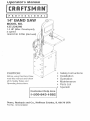
14"
SAW
MODEL
NO.
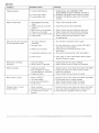
137.224240
1.5 HP (Max. Developed),
2 speed
1630/2730
RRM. (No load)
CAUTION:
Safety ]nstrucLions
Installation
,, Operation
Maintenance
Parts List
Spanish
Before using this Band Saw,
read this manual and follow
all its Safety Rules and
Operating Instructions.
Customer
He_p
Line
I °8,,00=843= 1682
Sears,
Roebuck
Part No. 137224240001
and Co.,
Hoffman
Estates,
tL 60179
USA
SECTION
Warranty
PAGE
.......
.........................................................
2
Product
Specifications
...........................
Safety
]nstructiQns
...................
. ..................
Accessories
and Attaci_ments
.........................
Cartoi_
Contents
Know Your Band
. .........................
..................
: ........
. ............
........
. .................................................
Saw ........................................................
6
8
Glossary
of Terms
........................................
Assembly
and Adjustments
................................................
Operation
...............................
: ..............................
Maintenance
............................................................
Troubleshooting
guide
.........................
Parts
..................................................................
MOTOR
BELT
..........
A 26
CUTTING
CAPACITY
Throat ............
Height ............
BLADE
Width ............
Length
.......
TABLE
Size .............
Tilt ..............
13-5/8"
6"
i
:....
1/8", 1/4", 3/8", 1/2"
91-1/2" to 93-1/2"
; ...............
. ....................
DUST COLLECTION
Power source ......
120 V AC, 60 HZ, 10 AMPS
Horsepower
.......
1.5 HP (Max. Developed)
Speed ........
1630/2730 F'eet per minute (No load)
Type .............
Induction
DRIVE
2
3
6
NET WEIGHT
.........
...
9
10
18
21
: .....
22
24
Yes
230 LBS
To avoid electrical hazards, fire hazards, or damage to
the toot, use proper circuit protection. Use a separate
electrical circuit for your tools.The Band Saw is wired at tile factory for 120V operation.
Connect to a 120V, 15 AMP branch circuit and use a 15
AMP time delay fuse or circuit breaker. To avoid shock or
fire, replace power cord immediately if it is worn, cut or
damaged in ally way.
16"X 16"
0 - 15° Left, 0 - 45 ° Right
, Some dust created by power sanding sawing, grinding, drilling, and other construction activities Contains chemicals
known to the state of California to cause cancer, birth defects or other reproductive harm. Some examples of these
chemicals are:
@ Lead from lead-based paints.
Crystalline silica from bricks and cement and other masonry products, and
Arsenic and chromium from chemically-treated lurnber.
Your risk from these exposures varies, depending on how often you do this type of work. To reduce your exposure to
these chemicals: work in a well ventilated area, and work With approved safety equipment, such as those dust masks
that are specially designed to filter out microscopic particles.
GENERAL
BEFORE
SAFETY
USnNG THE
11. WEAR PROPER APPAREL.
iNSTRUCTiONS
BAND
clothing, gloves, neckties, rings, bracelets, or other
jewelry which may get caught in moving parts.
Non-slip footwear is recommended. Wear protective
hair covering to contain long hair.
SAW
Safety is a combination of Comrnorl sense, staying alert
and knowing how to use your band saw.
12.
READ and become familiar with this entire ,nstruction
manual. LEARN the tool's applications, limitations,
and possible hazards
,
4.
KEEP
GUARDS
IN PLACE
and in working
order,
REMOVE ADJUSTING KEYS AND WRENCHES.
Form the habil of checking to see that keys and
adjusting wrenches are removed from the tool before
turning ON.
KEEP WORK AREA CLEAN,
benches invite accidents.
Cluttered
13
YOUR
ALWAYS
WEAR
EYE
WEAR A FACE MASK OR DUST
operation produces dust.
MASK.
Sawing
14. SECURE WORK. Use clamps or a vise to hold work
when practical. It's safer than usulg your hand and it
frees both hands to operate tool.
areas and
15. DISCONNECT
TOOLS before servicing,
and when
changing accessories,
such as blades, bits, cutters,
and the like.
DON'T USE IN A DANGEROUS
ENVIRONMENT.
Don't use power tools in damp or wet locations, or
expose
WEAR
PROTECTION,
Any band saw
can throw foreign objects into
the eyes that could cause
permanent eye damage.
ALWAYS wear Safety Goggles
(not glasses) that comply with
ANSI safety standard Z87.1. Everyday eyeglasses
have only impact-resistant lenses. They ARE NOT
safety glasses Safety Goggles are available at Sears,
NOTE: Glasses or goggles not in cornpliance with
ANSI Z87.1 could cause senous injury,
To avoid mistakes that could cause serious inju.ry, do not
plug the band saw in until you have read and understood
the following:
2.
DO NOT wear loose
them to rain. Keep work area well lighted
6.
KEEP CHILDREN AWAY. All viditors should be kept
at a safe distance from the work area.
16. REDUCE THE RISK OF UNINTENTIONAL
STARTING. Make sure the switch is in OFF position
before plugging in.
7.
MAKE
17
WORKSHOP
master switches,
CHILD-PROOF
or by removing
slarter
with _adlocks
k.e:ys. ,._
8.
DON'T FORCE THE TOOL. t will do the job better
and safer at the rate for which it was designed.
9.
USE THE RIGHT TOOL Don't force tool or the
18. NEVER STAND ON TOOL. Serious injury could occur
if the tool is tipped or if the cutting blade is unintentionally
contacted.
attachment to do a job for which it was not designe d.
10. USE PROPER EXTENSION CORD. Make sure your
extension cord is in good condition. When using an
extension cord, be sure to use one heavy enough to
, carry the current your product will draw.
An undersized cord will result in a drop in line voltage
and loss of power which will cause the tool to overheat.
The table on page 5 shows the correct size to use
depencling on cord length and nameplate ampere
rating. If in doubt, use the next heavier gauge. The
smaller the gauge nUmber, the heavier the cord.
SAVE THESE
USE RECOMMENDED
ACCESSORIES.
Consult the
Operator's Manual for the recommended
accessories.
The use of improper accessories
may cause risk of
injury to persons.
19. CHECK FOR DAMAGED PARTS. Before further use
of the tool, a guard or other part that is damaged
should be carefully checked to determine that it will
operate properly and perform its intended function.
Check for alignment of moving parts, binding of moving
parts, breakage of parts, mounting, and any other
conditions that may affect its operation. A guard or
other part that is clarnaged should be properly repaired
or replaced.
NSTRUCT ONS
3
20. NEVER
TURN
LEAVE TOOL RUNNING
UNATTENDED.
THE POWER OFF. Don't leave the tool until it
comes
to a complete
stop.
• 21. DON'T
OVERREACH.
balance at all tirnes.
Keep proper footing and
22. MAINTAIN TOOLS WITH CARE. Keep tools sharp
and clean for best and safest performance.
Follow
instructions
for lubricating
and changing acoessories.
23. DO NOT use power tools in the presence of
flammable liquids orgases.
24. DO NOT operate the toot if you are under the
influence of any drugs, alcohol or medication that
could affect your ability to use the tool properly.
25, Dust generated from certain materials can be
hazardous to your health. Always operate the band
saw in a well-ventilated area and provide for proper
dust removal. Use dust collection systems whenever
possible.
SPECIFIC
SAFETY
11. PLAN intricate and small work carefully to avoid
pinching the blade. Avoid awkward operation and
hand positions to prevent accidental contact with the
blade.
INSTRUCTIONS
1.
TO AVOID INJURY from unexpected movement, make
sure the saw is on a firm, level surface, properly
secured to prevent rocking. Make sure there is
adequate space for operating. B01tthe saw to a support
surface to.prevent it from slipping, walking, or sliding
during operation,
i
2.
TURN the saw OFF and unplu_l the saw before
moving it.
12. SMALL PIECES should be secured with jigs or
fixtures. Do not hand hold pieces that are so small
your fingers are under the blade guard.
13. SUPPORT round work properl.y (with a V-block or
clamped to the miter gauge) to prevent it from rolling
and the blade from biting.
14. CUT only one workpiece at a tirne. Make sure the
table is clear of everyttling except the workpiece and
its guides before you turn the saw on.
15. ALWAYS WATCH the saw run before each use. If
there is excessive vibration or unusual noise, stop
irnmediately. Turn the saw off. Unplug it immediately.
Do not start the saw again until the problem has
been located and corrected.
16. TO FREE any jammed rnaterial, turn the switch OFR
Remove the sw,itch key and unplug the saw. Wait for
all moving parts to stop before removing jammed
material.
17.
DON'T LEAVE the work area until all moving parts
are stopped. To childproof the workshop, shut off the
power to rnaster switches and rernove the switch key
from the band saw. Store it in a safe place, away
from children.
i
.
4.
USE THE CORRECT size and_style of blade.
USE blades rated at 2700 FPM or greater.
MAKE SURE the blade teeth point clown and
towards the table.
;.,-." _,-
6.
r
BLADE GUIDES, SUPPORT
BEARINGS,
AND
BLADE TENSION must be properly adjusted to avoid
accidental
blade contact and to minimize blade
breakage. To maximize blade support, always adjust
the upper blade guide and blade guard so that it is
1/8 inch above the workpiece.
7.
TABLE
LOCK
HANDLE
should
be tight.
8.
USE EXTR'A CAUTION
awkward workpieces.
9.
USE EXTRA SUPPORTS to prevent workpieces
from sliding off the table top. Never use another person
in place of a table extension, or to provide additional
support for the workpiece.
with large, very small
For your own safety, read the entire instructiorl manual
before operating the band saw.
1. Wear eye protection.
2. Do not wear gloves, necktie, or loose clotlling.
3. Make sure the saw is on a firm level surface and
properly secured.
4. USE ONLYTHE RECOMMENDED ACCESSORIES.
5. Use extra caution withvery large, very small, or
awkward workpieces.
6. Keep hands away from the blade at all times to
prevent accidental injury.
ELECTRICAL
POWER
SUPPLY
REQUIREMENTS
AND
MOTOR
SPECIHCATIONS
or
10. WORKPIECES must be secured so they don't twist,
rock, or slip while being cut.
SAVE THESE
To avoid electrical hazards, fire hazards, or damage to the
tool, use proper circuit protection. Use a separate electrical
circuit for your tools.Your saw is wired at the factory for
120V operation. Connect to a 120V, 15 Amp circuit and use
a 15 Amp time delay fuse or circuit breaker. To avoid shock or
fire, if power cord is worn or' cut, or darnaged in any way,
have it replaced immediately.
iNSTRUCTIONS
GROUNDING
INSTRUCTIONS
GUIDEUNES
This tool must be grounded while in use to protect
Operator from electrical shock.
the
IN"['HE EVENT OF A iVIALFUNCTION OR BREAKDOWN,
grounding provides a path of least resistance
for electric
current and reduces the risk of electric shock. This toot is
equipped with an electric cord that has an equipment
grounding conductor and a grounding plug. The plug
MUST be plugged into a matchirlg receptacle
that is
properly installed and grounded
in accordance
with ALL
local codes and ordinances.
DO NOT MODIFYTHE
PLUG PROVIDED.
receptacle,
have the proper
qualified electrician.
receptacle
If it will not fit the
installed
by a
FOR
CHEOK with a qualified electrician or service person if you
do not completely understand the grounding instructions, or if
you are not sure the tool is properly grounded
USE ONLY 3-wire extension
cords that
grounding
plugs and 3-pole receptacles
tool's plug. Repair or replace darn_.ged
immediately,
have 3-prong
that accept the
or worn cord
Be sure your extension cord is properly wired and in
good condition. Always replace a damaged extension cord
or have it repaired by a qualified person before using it..
Protect your extension cords flom sharp objects, excessive
heat and damp or wet areas.
Use a separate eiectrical circuit for your tools. This circuit
rnust not be less than #12 wire and should be protected
with a 15 Amp time lag fuse. Before connecting the motor to
the power line, make sure the switch is in tile OFF
position and the electric current is rated the same as the
current stamped on the motor nameplate.
lower voltage will damage the motor.
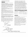
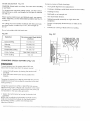
Fig. A
Running at a
_,_-. ,._
3-Prong Plug
G,oood,o
roog
Fig. IB
,
,
Grounoing LUg
(2J_
[i_
(when using 120 volls only)
Ampere
more
0
6
10
12
l]lan
Rating
nol
more
Ihar_
6
10
12
16
;__'_
Adapter
16
14
18
16
14
12
16
16
14
12
14
12
Not recommended
to rain
that has a
CAUTION:
In all cases, make certain the receptacle
is
properly grounded. If you are not sure have a qualified
electrician check the receptacle.
Receptacle
SAVE THESE
16
for use on a circuit
-- Make Sure This
_j- is
COnnected
Known
Groundto a
_
150'
18
receptacle
like the one illustrated in Fig. A
Fig. A shows a 3-prong electrical plug and receptacle
that has a groundihg
conductor. If a properly grounded
receptacle
is not available, an adapter ( Fig. IB} can be
used to temporarily
connect this plug to a 2-contact
ungrounded
receptacle. The temporary adapter should be
used only until a properly grounded
receptacle can be
installed by a qualified technician. The adapter {Fig. IB}
has a rigid lug extending from it that MUST be connected
to a permanent
earth grourld, such as a properly
grounded
receptacle box. The Canadian
Electrical Code
prohibits the use of adapters.
I _'_'---,
_¢3
Total length of cord In feet
25'
50'
:i00'
TMs band Saw is for indoor use only. Do not expose
or use in clamp locations.
This tool is intended
i
CORDS
USE PROPER EXTENSION CORD. Make sure your
extension cord is in good condition. When using an
extension cord, be sure to use one heavy enough to carry
the current your product will draw. An undersized cord will
result in a drop in line voltage and in loss of power which will
cause the tool to overheat. The table below shows the
correct size to use depending on cord length and
nameplate ampere rating. If in doubt, use the next heavier
gauge. The smaller the gauge number, the heavier the cord.
IMPROPER
CONNECTION
of the equipmenl
grounding
conductor can result in risk of elechic shock. The
conductor with the green insulation (with or without yellow
stripes) is the equipment
grounding
conciuctor. If repair or
replacement
of the electric cord or plug is necessary, DO
NOT connect the equipment grounding
conductor to a live
terminal.
EXTENSION
MNSTRUCTNONS
AVAILABLE
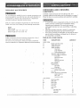
UNPACKING
CONTENTS
ACCESSORIES
Do not attempt to modify this tool or create accessories
recommended
for use with this tool. Any such alteration
modification
is misuse and could.result
in a hazardous
condition
leading
to possibl e serious
not
or
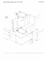
Carefully unpack the band saw and all its partS, and
compare against the list below and the illustration on page 7.
Place the saw on a secure surface and examine it carefully.
injury.
Visit your Sears 14ardware Department
or see the Sears
Power and Hand Tool Catalog for the following accessories:
"
To avoid injury from unexpected Starting, do not plug the
power cord into a power source receptacle during
unpacking and assembly. This cord must remain
unplugged whenever you are assembling or adjusting
the saw.
,,
Although compact, this saw is heavy. To avoid back
injury, get help whenever you have to lift the saw.
If any part is mis'sing or damaged, do not plug the band
saw in until the rnissing or damaged part is replaced_
and assembly is complete.
ITEM
Miter gauge
Blade width:
Blade
length:
1/8", 1/4", 3/8",
91-1/2"
AND CHECKING
1/2"
to 93-1/2"
Follow inshuctions
filat accompany
accessories.
Use of
improper accessories
may cause hazards.
Do not use any accessory unless you have completely
read the insIruction or Operator's Manual for that accessory.
_'
TABLE
OF LOOSE
PARTS
ITEM
DESCRIPTION
BAND SAW
A
B.
C.
D.
Band
Table
Table
Table
E.
F.
G.
H.
I.
J.
K.
LEG STAND
L.
M.
M-1
N.
O.
R
Q.
saw with motor
with insert
trunriions
hardware
Flex bolts
Lock washers
Table alignment pin
Trunnion support bracket
Trunnion support hardware
Long bolt
Short hex. bolt
Hex nut
Table lock knobs
Washers
Miter gauge
Sawdust port
Hex bolts
Washers
Power cord hooks
Phillips head bolts
Hex. key
Stand attachment hardware
Large washers
Hex. nuts
Long hex. bolts
Stand top plate
Sled plate
Back plate
Door plate
.Tool Tray
Foot pads
Bag:
Carriage bolts
14ex.nuts
Washers
_Q_ANTITY
1
1
2
6
6
1
1
2
1
1
2
2
1
1
2
2
2
2
1
8
4
4
1
2
1
1
1
4
32
32
32
UNPACKING
YOUR
BAND
SAW
%%%
B
C
E
F
o'o'
H
A
K
M
©
P
Q
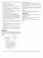
G •
Upper
covet"
Upper blade wheel
Lower blade
Lower blade
guide
support bearing
,_
Upper blade
support bearing
Blade
ON/OFF switch
Fable insert
Wheel
brush
Table removed for clarity
of illustration
r
Table
Lower cover
Sawdust
_'_Table
lock knob
.sort
"------ Lower
blade wheel
Blade tension
knob
Upper guide
bar
L
Blade tension
gauge
Blade tracking
knob
Power cord wrap
Upper guide m
lock knob
Mounting
boles
(
c
Blade guide ---/
slide knob
Table
aligning pin
F-_
Table trunnion
tilt:scale
......8
t--,J
-= ="
Table tilt stop bolt
Motor cord
Motor--
Miter gauge storage
1
Stand top
plate
Mounting holes _-'_
Stand
I
o
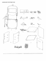
CRAFTSMAN
BAND
LEADING EDGE - The end of the workpiece guided into
the cutting tool first.
SAW TERMS
BLADE GUIDES - Support tile blade and keep it from
twisting during operation. Blade guides must be adjusted
when blade is changed or replaced.
UPPER GUIDE LOCK KNOB -,-locks the upper.slide. Use it
after you adjust the upper guide assembly to make sure
Upper blade guide just clears w0rkpiece before cutting. Upper
guide lock knob must be tightened before the band saw is
turned on.
TABLE LOCK KNOB -locks
TILT (BEVEL) SCALE -shows
tilted for bevel cutting.
the degree the table is
BLADE TRACKING
KNOB -adjusts
blade position
always runs in the center of the wheel.
so blade
SAWDUST PORT -helps keep the machine free from
sawdust. The sawdust port makes.an excellent Ilook-up for
a wet/dry vacuum.
_ .
!
i
ON/OFF SWITCH -has a built-in 8hild safety lock. To lock
the switch in the OFF a0sition, remove the switchlkey from
the switch.
_
i
BEVEL CUT -An
workpiece.
COMPOUND
RESAW -A cutting operation to reduce the thickness of
the workpiece to make thinner workpieces.
RESIN -A sticky sap that has hardened.
RIPPING CUT - A cutting operation along the length of the
workpiece.
the table in place.
BLADE TENSION KNOB -- controls the amount of blade
tension when changing blades.
WOODWORKING
MITER CUT - An angle cut made across the width of a
workpiece.
R.P.M. - Revolutions per rninute. The number of turns
completed by a spinning object in one minute.
SAW BLADE PATH -The area of the workpiece or table
top directly in line wit!] the travel of the blade or the part of
the workpiece which will be cut.
SET -The
distance between two saw blade teeth tips, that
are bent outward in opposite directions tO each other. The
further apart the tips are, the greater the set.
TRAILING
END -The
WORKPIECE - The item being cut. The surfaces of a
workpiece are commonly referred to as faces, ends, edges.
WORKTABLE -The surface on which the workpiece rests
while performing a cutting or sanding operation.
TERMS
angle cut made through tile face of a
_,
_..
CUT - A simultaneous
bevel and miter cut.
Keli Leading,_
CROSSCUT-A
workpiece.
workpiece end last cut by the blade.
Sawblade Pall]
cut made across the width of the
Surface
F.P.M.. Feet per minute. Used in reference to the sudace
speed of the saw blade.
FREEHAND - Performing a cut without using a fence
(g'uide), hold-down or other proper device to prevent the
workpiece from twisting during tile cutting operation.
Workpiece
Trailing Edge
GUM -A
HEEL
sticky sap-based residue from wood products.
- Misalignment
of the blade.
KERF - Tile material removed by a blade in a through cut,
or the slot pr0diJced by the blade in a n0n-through
or
partial cut.
ASSEMBLY
TOOLS
NSTRUCTRONS
Although compact, this saw is heavy. [b avoid back injury, ge
help to lift the saw.
NEEDED
ASSEMBLE
'Combinationsquare
1.
EEI__-3_
_ZLI_--_LTJ___Z[2-1__21
2.
Phillips screwdriver
Adjuslable wrench
Straight edge
3.
Feeler'gauge - size 0.02
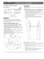
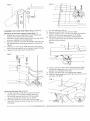
BAND SAW TO LEG STAND
(Fig. l
Lift the saw body (1) and place on tile leg stand (2),
aligning the mounting holes (3) of the saw base with the
foul" mounting holes of ttie leg stand top plate.
Attach timeband saw to the stand with four long hex heac
bolts (4) and four flat washers (5).
Place a flat washer (5) arid hex nut (6) on each bolt from
the underside. Hand tighten.
Tighten all mounting bolts and nuts with a wrench.
Tighten all leg stand bolts and nuts with the wrench.
4.
5.
Fig.
D
For your safety, never connect plug to power source
receptacle until all assembly and adjustment steps are
completed, and you have read and understood the safety
and operating instructior/s.
CLOSED
STAND
ASSEMBLY
(Fig. C)
1. Attach LH. side plate(3) to the top plate (1) with four
carriage Screw (10), flat washer(11) and hex. Nut(12):
2. Repeat above steps for the R.H.: Plate(4).
3. Attach tools tray(2) between the, L.H. Side plate and R.FI.
side plate with eight carriage sc!ew(lO), flat washer (11)
and He)(. Nut(12).
4,
Attach back plate(5) to the top plate(l) and tools tray(2)
with four set screw(9).
5. Mount the door plate(6) :to the R.14.Side plate(4) and
fasten with four set screw (9).
6. Fit knob(15) to the door plate(6) with one Hex. Screw (14).
7. Place four pad(13) to each leg.
o
i
i
f
i
i
6
Fig. C
o
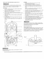
THE
SAWDUST
The sawdust
PORT
o
(Fig.
E )
port has a 2-1/2"(O.D)/2-1/4"(I.D)
ing, suitable for attaching to a wet/dry
keep the work area free of sawdust.
1.
2.
3.
4.
vacuLIm
diameter opel
hose to hell
Remove the bolts (1) and washers (2) from the sawdust
port (3).
Open the lower wheel cover (4.).
Attach the sawdust port to the edge of time wheel cover,
using the same hex. head bolts and washers.
Tighten time bolts and close the cover.
1112 _-_
-
._._..__. --
1o
I
79 -
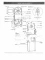
ASSEMIBLE THE £_AND SAWTABLE (Fig. F, G, H, I,}
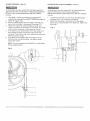
Mounting the trunnion support bracket (Fig. F )
1. Remove the Iwo hex head bolts (1) and washers (2),
located, on the lower band saw housing.
2. Place the trunnion support bracket (3) on the saw body,
as shown, aligning the mounting holes.
3. Place the washers oil the hex head bolts, and insert into
the threaded holes, through the bracket and saw body.
Tighten.
4. Thread a nut (4) onto the table stop bolt (5) and screw
both into the rear tab (6) on the trunnion support bracket.
5. Tighten the nut down onto the bracket tab.
Fig.
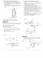
9. Turn the table right side up.
10. Remove the table insert (13) frorn the table.
11. Guide the table slot (14) over the saw blade and rotate a
1/4 turn, so the slot is perpendicular to the blade.
12. Placing the scale lock knob bolts (10) through the
trunnion brackel holes (15) as shown, lower the table
onto the trunnion bracket.
Fig. H
f
F
•
10
1
15
2
6
Mounting
the tame (Fig. G, H, i}
6.
On the underside of the table (7), place the scale
brackets (8) on the bracket mounting ho}es (9).
7.
Be sure the long loci< knob bolts (10) are placed
upwards through the bracket slots as shown.
8,
Place lock washers (11) on three short hex head
bolts (12). Thread thebolts through the mounting holes
and tighten,
13. Place a lock knob (16) on each scale knob bolt. Adjust
the table by aligning the zero scale rnark to the scale
pointer (17), and tighten the knobs.
14. Replace the table insert (13), aligning the indents.
15. Place the table aligning pin (18) in the hole at the front of
the table, and tighten.
16
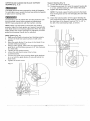
INSTALLING
AND REMOVRNG
BLADES
(Fig.
Installing
1. Make sure the blade tension knob (1) is turned
counterclockwise until it stops.
2. Remove old blade as explained in "Removing".
3. Guide the new. blade (7) througb the table slot (11). '
Make sure the blade teeth are pointing forwat:d and
down.
J)
To avoid injury from accidental starting, always turn the
switch C)FF and remove the plug frorn the power source
before moving, replacing, or adjusting the blade.
Removing
1. Loosen the blade tension by turning the blade tension
knob (1) counterclockwise.
2. Remove the table insert (2) and remove the table
aligning pin (3) from the table.
3. Open the upper and lower wheel cover doors (4).
4. Loosen the two Phillips screws (5) and remove the upper
blade guard (6).
5. Remove tile blade (7) frorn tile upperand lower blade
guides (8).
6. Carefully pull the blade from tile side slot (9) and from
the wheels (1.0).
7. Swing the left side of the blade toward you, turning the
blade so it will fit through the slot (11) in the table, and
rernove.
NOTE: To avoid lifting the workl:)iece, the blade teeth
must point downward toward the table.
4.
Swinging the left side off the blade away and back, place
the blade on the upper and lower wheels (10).
5. Place the blade carefully between the upper and lower
blade guides (8).
6+ Slide the blade ir_tothe slot (9) at the left of the wheels,
and make sure the blade is positioned at the middle of
tile wheels.
.'
7.
8.
9.
Turning the blade tension knob (1) clockwise, tigtlten the
tension until the blade is tight on the wheels.
Replace the table insert (2) and the table aligning pin (3),
Adjust the blade tracking and tension properly (See
ADJUSTMENT INSTRUCTIONS section) before
operating the band saw.
Fig. J
To avoid injury, the blade tension, tracking, and upper and
lower guides and bearings must be properly adjusted before
operating the band saw. (See ADJUSTMENT
INSTRUCTIONS section)
10
\
MITER GAUGE (Fig. K)
A miter gauge (1) is supplied with your band saw to be used
in the table slot (2) on the right side of the blade. The miter
gauge can be tilted 0 ° and to 45 ° right or left, to maintain a
accurate angle for your workpiece. A bracket is provided on
the leg stand for convenient miter gauge storage.
6
5
8
Fig. K
3
1
--
8
10
(
Before operation always make sure the blade is in center
of table insert slot.
"_'
t
iNSTALLPOWER
CORDBRACKETS
(Fig,L)
1. Powercordbrackets
(1)areprovidect
forconvenient
cordstorage.
Atlachthepowercordbrackets
totheback
ofthesawbocty,
asshown,withtwoPhillipshead
screws(2).Tighten.
2. Wrapthepowercordontothebrackets
whentheband
sawis not ill use, to prevent damage to the cord.
Fig.
L
ADJUSTMENT
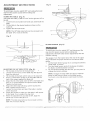
ADJUSTING THE 90 ° TABLE STOP (Fig. N)
1. Loosen the table lock knobs (2) and tilt the table to
the right.
2. Loosen the nut (4) on the table stop bolt (5) and lower
the stop bolt as far as possible.
3. Tilt the table until it rests on the stop bolt.
4.. Place a combination square (6) on the table with the
heel of the square against the saw blade.
5. Adjust the tilt of the table left or right until it is 90 ° to the
blade. Make sure there is no space between the square
and the blade.Tighten the table lock knobs.
6. Adjust the table stop bolt up until it touches the table.
Tighten the jarn nut down to the support bracket,
7. Loosen the lock knobsand see that the table is resting
on the stop bolt.
8. Check the scluare to make sure the table is still square to
the blade. If not, readjust the stop bolt.
9. When the adjustment is accurate at 90 °, align the
pointer (7) to 0° on the scale (8).
gNSTRUCT ONS
To avoid injury, turn the switch OFF and unplug the barld saw
from the power source before making any adjustments.
TABLE
ADJUSTMENTS
(Fig.
M, N)
Tilting the table (F_g. IBm)
i
The band saw table (1) tills 0° an@to 45 ° right
1.
2.
3.
2
Loosen both table lock knobs (2) undemeath:the table.
Tilt the table to the desired angle on the scale (3)
underneath the table.
Tighten the two table lock knobs.
4
Make sure the blade is in center of table insert slot(2)
Then tighten the screw(A-C) which are under the table on
both sides as shown (Fig O.)
Fig. O
_,
13
ADJUSTMENT
INSTRUCT ONS
Fig. Q
x__/
To avoid injury, turn the switch OFF and unplug the band
saw fiom the power source before making any
adjustments.
TSLTmNGTHE TABLE t_Fig. P)
Tile band saw table (1) tilts 0° to 45 ° to tile right and 15° to
the left.
!. Loosen both star handle lock knobs (2) underneath the
table.
2. Tilt tile table to the desired angle as shown on the
scale (3).
3. Tighten the two loci< knobs.
NOTE: The 90 ° table slop bolt must be removed to tilt
the table 10° or more to the left.
Fig. P
BLADE
TENSION
(Fig.
i_)
To avoid injury, turn the switch OFF and disconnect the
saw from the power source before making any
adjustments. NEVER rnake tension adjustnqentswith the
machine running.
ADJUS'NNG THE 90° TABLE STOP (Fig. q),,:..
1. Tilt the table to the front of the band saw.
O
t'_,
Loosen the jam nut (1) on the table stop bolt (2) and
lower the stop bolt.
3. Tilt the table to the back until it rests on tile stop bolt.
4. Place a combination square (3) on the table with the
heel of the square against the blade (4.).
5. Adjust the tilt of the table until it is 90 ° to the blade and
there is no space between the square and the blade.
Tighten the lock knobs.
6. Adjust the table stop boli (2) up until it touches the
table. Tighten the jam nut (1).
7. Loosen the lock knobs and see if the table is resting
on the stop bolt.
8. Check the square to make sure the table is still square
to the blade. If not, readjust the stop bolt.
9. When the adjustment is accurate at 90 °, align the
pointer (5) on the scale (6) to 0 °.
NOTE: The table stop,bolt must be removed
table 10 °or more to the left.
to tilt the
The gauge (1) on the bracket (2) at the rear of the upper
wheel indicates the proper tension for the various blade
widths.
1. Set the blade tension gauge (1) to correspond with the
blade width, as shown.
2. Turn the blade tension knob (3) clockwise to tighten
the blade, counterclockwise to loosen.
3. As you become familiar with the saw, you may want to
change the tension settings.
NOTE: Changes in blade width and type of material
being cut will have an effect on the blade tension.
Too much or too little tension could break the blade.
Fig. R
2
1
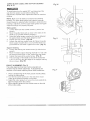
BLADE TRACKING
(F_g. S)
UPPER
BLADE
GUIDE
ASSEMBLY
(Fig.
T}
To avoid injury, turn the switch OFF and disconnect the
saw from the power source before making any adjustments.
NEVER make tracking adjustments with the machine
running.
To avoid injury, turn the switch OFF and disconnect the
saw from the power source before making any
adjustments. NEVER make adjustrnents with the machine
running.
1.
1.
2.
3.
4.
5.
6.
The blade (!) must be tensioned properly before
adjusting the tracking. (See BLADE TENSION on page 15).
Open the upper cover,
o..
Move tile blade guides (2) and support bearings (3)
away frorn tile blade, if necessary. (See page 17).
Rotate the wheel (4) slowly forward by hand, and
check the position of the blade on the wheel. The blade
should remain centered on the wheel as it turns.
If the blade moves toward the front of the wheel, turn
the tracking knob (5) on the rear of the band saw
clockwise. This tilts the top of the wheel and moves the
blade toward the center.
If the blade moves toward tile back edge, turn the
tracking knob counterclockwise, moving the blade
toward the center.
2.
Loosen tile lock knob (1) and move the blade guide
assembly (2) to 1/8" above the workpiece.
Rotate the assembly, if necessary, until the guide ,
blocks (3) are flat (parallel) to the blade (4). Tighten the
lock knob.
Fig. T
-t
NOTE: Turn the tracking knob SLIGHTLY to make blade
tracking adjustments.
Fig: S
3
4¸
2
1
'2
UPPER BLADE GUIDES AND BLADE SUPPORT
BEARING (Fig. U, V)
The blade guard has been removed for clarity of illustration.
To avoid injury never o,perate the band saw without all guards
in place and in working order.
To avoid injury, turn the switch OFF and disconnect the saw
from the power source before making any adjustments.
NEVER make adjustments with the machine running.
Support bearing (Fig, V)
9. Loosen the thumb screw (6).
10. Turning the rear knob (7), move the support bearing (8)
in or out, until the bearing is 1/64" behind the blade.
11. Tighten the thumb screw (6).
NOTE: The blade support bearing prevents the blade
from moving back too far and damaging the saw teeth
setting.
12. Check the lateral position of the support bearing (8).
The vertical back edge of the blade (3) should overlap
the front face of the support bearing 1/16" to 1/8" to
the left of the right bearing edge, as shown.
NOTE: Make sure the blade is tensioned and tracking
properly. Adjust the blade guides and support bearing after
each blade tension and tracking adjustment. When the upper
blade guides and support bearings are adjusted, the lower
guides and bearings should also be adjusted.
Blade guides (Fig. U)
1. Make sure the blade is tensioned and tracking properly.
2. Loosen the front hex socket screws (1) with a hex
wrench.
3. Move the guide blocks (2) as close to the blade (3) as
possible without pinching it.
4. Using a feeler gauge, make sure the space between
guide block and the blade measures
0.02" (the thickness
r
of a dollar bill).
5. Tighten the hex socket screws.
6. Loosen tile side thumb screw (4)by turning
counterc!ockwisel
7.
8.
Fig. V
(
3'
[iJrn the rear knob (5) to move tl)e blade guide brackets
in or out until the guide blocks !2) are just behind the
blade teeth.
Tighten the thumb screw.
Fig. U
-L
2
' _::.:'
i::'::: _'
:::::::::::::::::::::
16 ..................................................................................................................
LOWERBLADEGUiDESANDSUPPORT
BEARING
(Fig. W, X)
Fig.W
To avoid injury, turn the switch OFF and disconnect the
saw from the power source before making any
adjustments. NEVER make acljustments will] the machine
running.
NOTE: Make sure the blade is tensioned and tracking
properly. Tile lower blade guides and support bearings
should always be adjusted after the blade is tensioned, the
tracking is adjusted, and the upper blade guides and upper
support beanngs are properly adjusted.
Blade guides
1. Loosen both front hex socket
wrench.
2.
3.
4.
5.
screws
\
\
(1) with a hex
Move tile guide blocks (2) as close to the sides of the
blade (3) as possible without pinc!ling it.
Using the feeler gauge, measure the spaces between
the guide blocks and the blade. Adjust to 0.02".
Tighten the hex screws.
(Fig. W)
Loosen lhe side hex socket screw (4). Move tile guide
block support bracket (6) in or out until the blocks are
just behind the saw teeth. Tighten the screw. (Fig. X)
Fig. X
7
f
Support bearing
6. Loosen the bearing hex socket screw (7) with the hex
[
wrench.
7.
8.
9.
Move the blade support bearing shaft (8) in or out until
the support bearing (9) is 1/64"; behind the saw blade.
Tighten the bearing hex socketiscrew. (Fig. X)
The back edge of the blade (3) Ishould be positioned
1/16"to 1/8" from the right edge of the support bearing
(9), as shown. (Fig. W)
PULLEY ALIGNMENT (Fig. Y)
Tile pulley alignment has been factory adjusted and
shouldn't require further adjustrnent. If adjustnlents are
required or belt needs replacing fo ow thes6 p o_edu es
1
Fig. Y
1. Place a straight edge in the front groove of both pulley s,
behind the blade wheel.
2. Turn the hex socket screw (1) in the side of the nlotor
pulley (2) to loosen the pulley on the shaft.
3. Adjust the motor pulley in or out on the motor shaft (3) to
align the edges of tile two pulleys.
4. When aligned, tiglqten tile hex socket screw on the side
of the motor pulley.
2
8
E:]ASNC SAW OPERATF ONS
"ON/OFF" SWFTCH (Fig.. Z)
The keyed switch is intended to prevent unauthorized
use of the band saw.
1. 7o turn the band saw ON insert the yellow key (1) into
the key slot (2) in the center of ttfe switch.
2. Push the key firmly into theslot, then push switch
to the ON position to start the band saw.
3. To tLirn lhe band saw OFF push the switch to the
down position.
4. Remove the yellow switch key, when the saw has come
to a complete stop., by gently pulling it outward.
7b avoid twisting the blade do not turn sharp corners; saw
around corners.
A band saw is basically a "curve-cutting" saw, It is not
capable of doing intricate inside cutting as can be done
with a scroll saw.
It is also Llse'dfor straight line operations such as
crosscutting, ripping, mitering, beveling, compound cutting,
and resawing.
7
To avoid blade breakage, fire or other damage or injury,
NEVER use this band saw to cutmetals.
CUTTING
Renlove the switch key whenever the saw is not in use.
Place it in a safe place and out of reach of children.
Fig. Z
CURVES
When cutting curves, carefully turn the workplece so the
blade follows without twisting. If the curve is so sharp that
you repeatedly
back up and cut new kerf use a narrower
blade, or a blade with more set (teeth further apart). When
a blade has more set, the workpiece turns easier but the
cut is rougher.
When changing a cut, do not wittTdraw the workpiece frorn
the blade. The blade may _:jetdrawn of[ the wheels,
To change a cut, turn the workpiece and saw out through
the scrap material area.
When cutting long curves, make relief cuts as you go
along.
I
GENERAL
CUTTING
For your safety, read and understand all GENERAL and
SPECIFIC SAFETY INSTRUCTIONS on pages 3-5 before
using the band saw.
Operating band saws involves a certain amount of hazard.'
Before attempting regular work, Use scrap lumber to check
the settings, and to get the feel of operating the band saw.
Read instructions and plan your work before cutting a
workpiece.
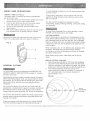
CIRCLE CUTTING
(Fig. AA)
1. Adjust the guide assembly to 1/8" above the workpiece.
2.
Use both hands while feeding the work into the blade
Hold the workpiece
firmly against the table. Use gentle
pressure: Do not force the work, ALLOW the blade to cut.
3. Tt7e smallest diameter circle that can be cut is
determined
by the width of the blade. For example_
1/4" wide blade will cut a minimum diameter of
approximately
a
1-1/2".
Fig. AA
Do not turn the power ON until after you have made all •
adjustments, checked that the guard is in place, and turned
the wheel by hand Io make sure all parts workproperly.
Always keep the guide assembly 1/8" above the workpiece.
MinirlTum
Do not force the workpiece against the blade. Light contact
permits easier cutting and prevents unwanted friction and
heating of the blade.
Sharp saw blades need little pressure for cutting. Steadily
move the workpiece against the blade without forcing it.
18 i;-:::S:.!7:
2-112"D
Circle
Diameler
1/Z'
Blade
Width
EIL.ADK
SE1LEC'TIO_
Fig. E_B
CAUTION:Bladeteetha_"e
Sharp.Usecarewhenhandling
a sawblade.
Forlongestwearandbestcuttingresults,usethe correct
,blade tMckness, width, and teml:?er for the type of material
you will cut.
For cutting wood and similar rnaterials with this band saw,
purchase blades in widths up to 1/2", and a length of
93-1/2".
with this band
Forcing or twisting a wide blade around a short radius.
_,
Feeding too fast.
_,
lbo much blade tension.
_,
Setting top guide assembly too high above the
workpiece.
o
Lumpy or improperly finished braze or weld on the
blade.
-
Continuous
running of blade when not cutting.
saw.
Fig. BEi
Fig, CO
Operation
Recommended BSade W_d_th
(_nehe_}
Cross Cutting
1/4, 3/8, t/2
Mitering
1/4, 3/8, 1/2
Beveling
1/4, 3/8, 1/2
Compound Cutting
1/4, 3/8, t/2
Circle Cutting
See chart on pg. 18
Curve Cutting
1/8, _1/4
i
CHANGING
Poor guide alignment and adiustment.
Dull teeth or not enough set.
When sawing small curves and delicate work, use narrow
blades. Otherwise, use tl_ widest blade possible. See Fig. AA
on page i 8.
..
Do not cut metals
Common causes of blade break.age:
SPEED
SETTING
5
(Fig. CC}_
To avoid injuries, turn the power switch OFF and
disconnect the band saw from the power source]
1. Loosen the belt tension by turning the tension lock
handle(5).
2. Open the lower wheel covet and re-position the
V-bell(3).
3hanging the speed from 1630 to 2730 FPM: first remove
_elt(3) from the band saw pulley(4); reposilion in the saw
:_ulleygroove(I).
3hange I:he speed frorn 2730 to 1630 FPM: first remove
_elt(3) Irolll the motor pulley(5) and reposition in the motor
_ulley groove(2). Rernove the bell from the saw pulley (4)
:_ndreposition in the saw pulley groove(2).
}. Tighten lhe belt tension by turninq the tension lock
handle(6).
_OTE: After re:adjusling belt posil.ion and belt tension,
verify and re'-adjusl the setl:ings for the blade tension
and tracking position, guides and bearings (See
\djusimenl section).
19
3
4
Applya thir_coatofpastewaxonthetablesothatthewood
slideseasilywhilecutting.
TO INSTALL A NEW BELT (Fig. DD)
1. Open the lower wheel door.
2.
Loosen the blade tension by turning the blade tension
lock knob (t).
3. Remove tile blade from the lower blade wheel.
4.
5.
6.
7.
8.
9.
Loosen and remove the hex head bolt (2) and flange (3)
on the lower blade wheel.
Remove tile lower blade wheel.
'Turn the belt tension handle (4) on the rear of the saw
tlousing to loosen the v-belt tension.
Remove the v-belt (5).
Check the alignment of the two pulleys.
If the edges of the two pulleys are not aligned, see
"ALIGN THE PULLEYS" in ADJUSTMENT
section.
10. Place the new v-belt on the saw pulley and the motor
pulley. See OPERATION
section "CHANGING
SPEED
SETTINGS" on page 19 for proper belt placement.
i 1. When positioned properly, tighten the v-belt tension by
turning tile tension lock handle.
NOTE: The pulley belt is properly tensioned when there
is 1/2" deflection if pressed in tile center between the
pulleys.
BLADE WHEEL TIRES
Pitch and sawdust that build up on the tires should be
removed with a stiff brush or scrape off with a piece of wood.
NOTE: To avoid damaging the tires do not use a sharp knife
or any kind of solvent,
When the tires become worn they should be replaced. When
replacing tt]e tires, stretch them around the wheels but do
not glue thern on.
MOTOR
Frequently blow or vacuum out any sawdust from the motor.
Follow lubrication instruction on the motor label.
To avoid electrocution or fire, immediately replace a worn, cut
or damaged power cord.
LUBRICATION
All of the bearings are packed with grease at the factory.
They require no further lubrication.
CAUTION: Never put lubricants on tile blade while it is
spinning.
12. Replace the blade wheel. Push the wheel in firmly until
it is louching the saw pulley. Replace and tighten the
flange and nut.
13. Reinstall tile blade (See INSTALLING BLADES Section
on page 12).
i
14. Adjust the blade tension, tracking, ;and the upper and
lower blade guides and bearings b'efore operating the
band saw.
"
To avoid injury, the blade tension, tracking, and upper and
lower guides and bearings must be properly adjusted before
operating the band saw. (See ADJUSTMENT INSTRI.JCT!ONS
section)
1
Fig. DD
4
_-'
3
....
5
GENERAL
MADNTENAINC,
E
For your own safety, turn switch OFF and remove the plug
from power source receptacle before maintaining, cleaning,
adjusting, or lubricating your band saw.
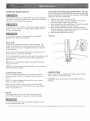
ADJUSTINGTHE UPPER BLADE GU_DETRAVEL (Fig. EE)
If the upper guide bar assembly will not move up and down
easily or falls when the lock knob is loosened, the following
adjustment should be performed.
1.
2.
3.
To avoid fire or toxic reaction, never use gasoline, naphtha,
acetone, lacquer thinner or similar highly volatile solvents
to clean the band saw.
4.
5.
To avoid eye injury from blowing debris, weal safety
goggles when blowing out sawdust.
Remove the guide bar lock knob (1);
Using a 5mm hex "L" wrench, tighten or loosen the
screw (2) located behind the lock knob.
Move the guide bar (3) up and down to ct-leck for smooth
rnovernent and ability to hold its position.
Make further adjustments .to the screw as required.
Properly adjusted, the guide bar should move smoothly
and hold its position when released.
Reinstall the guide bar lock knob.
Fig,
EE
BAND SAW
Sawdust will accumulate under the table and base. This
could cause difficulty in the movement of the table when
setting up a band saw cut. Frequently blow out or vacuurn
up the sawdust.
Keep your band saw clean. Remove the sawdust from the
inside. Vacuum or blow out flequently.
Do not allow debris :Eobuild up on theetable, the guides, or the
support bearings. Clean them with draftsman Gum and
Pitch Remover.
NOTE: Do not immerse the support_bearings
in the gum
p
an_._itch remover.
Apply a thin coat of paste wax.on the table so that the wood
slides easily while cutting.
_!...
_,_
BLADE WHEEL TIRES
Pitch and sawdust that build up on the tires should be
removed with a stiff brush or scraped off with a piece of
wood.
NOTE: To avoid damaging the tires do not use a sharp
knife or any Mnd of solvent.
When the tires become worn t.tTeyshould be replaced.
.When replacing the tires, stretch them around the wheels
but do not glue them on.
MOTOR
Frequently blow or vacuum out any sawdust from the
motor. Follow lubrication instruction on the motor label.
To avoid electrocution or fire, immediately replace a worn,
cut or damaged power cord.
LUBRJCATnON
All of the bearings are packed with grease at the factory.
They require no further lubrication.
CAUTION: Never put lubricants on the blade while it is
spinning.
To avoid injury from an accidental
making any adjustments.
start,
turn the switch
OFF and always
remove
the plug from the power
source
before
.
All electrical or rne(;hanical
Service Center.
repairs
should
be done
only by qualified
service
technicians,
Contact
the nearest
Sears
GENERAL
Problem
Probable
Cause
Blade does not run in the
center of the
upper wheel.
1. Not tracking properly.
2.
Band saw slows down
1. Belt too loose.
1. Adjust 'belt tension. See ASSEMBLY AND
ADJUSTMENTS
section "BLADE TENSION".
2. Cuttirlg
2. Stop feeding,
Defective
Remedy
blade.
when cutting.
too small a radius.
3.
!
Ddlll blade.
4.
O_'erloading
braking
motor.
1. Too much tension
the blade.
2.
back up the material slightly, until the
band saw speeds up.
3. Replace blade.
4. Slow down, trying to cut too fast. See "MOTOR
TROUBLESHOOTING
GUIDE" on page 23.
i
Blades
1. Adjust tracking. See ASSEMBLY AND ADJUSTMENTS
section "BLADE TRACKING".
2. Replace blade.
on
Kink in the blade caused by
cutting too small a radius or
turning thr_'_aterial too fast
1. Adjust tension. See ASSEMBLY AND
ADJUSTMENTS section "BLADE TENSION"
2. Use correct cutting technique.
See OPERATION section "GENERAL CUTTING".
when cutting.
Blade dulls too quickly.
1. Blade guides
the teeth.
2. Cutting
Band saw vibrates.
set too close to
incorrect
material.
1. Too much tensionon
motor belt.
1. Adjust upper and lower blade guides.
2. See OPERATION
1. Adjust according
ADJUSTMENTS
section "BLADE
SELECTION".
to ASSEMBLY AND
section, "INSTALL THE 'BELl"'.
MOTOR
Problem
Pm'obable Cause
Noisy operation.
1. Incorrect belt tension.
2. Loose motor pulley.
3. Loose pulley cover•
Motor will not start.
1. Adjust tension. See ASSEMBLY AND
ADJUSTMENTS section "INSTALL THE BEET".
2. Readjust and tighten motor pulley set screw.
3. Readjust and tigtlterl pulley cover rnounting
screws.
1. Not plugged into power
outlet.
1. Plug it into the power outlet.
2. Switch and keY not in ON
position.
3. Motor cord cut or abraded.
2, Insert key and turn the switch ON.
4, Plug on cord is faulty.
5. Fuse on circuit breaks open.
6. Faulty motor
Motor will not start and fuse
or circuit breaker opens.
I Remedy
1. Too many electrical
machines.
2. Incorrect fuse,
3. Wheels do not rotate.
4. Undersized extension cord.
3. Take to Sears Service Center for new cord.
4. Take to Sears Sef:vice Center for new plug.
5. Re-set; may be too rnany rnachines on line.
6, Take to Sears Service Center for repair
or replacement.
1. Turn off other machines and try again,
2. Try tirne delay fuse, or go to circuit with higher
rated fuse or circuit breaker.
3. Unplug and turn wheels by hand, move
obstruction.
4. Use correct size extension cord; see page 5.
5. Short circuit.
5. Cord, plug, or motor need repair; take to Sears
Service Center for repair.
Motor fails to develop
full power.
1. LoW
line voltage.
t
2. Fa_Jlty rnotor or capacitor.
1. Check power lille for proper voltage.
2. Take to Sears Service Center for evaluation.
Motor Overheats.
1. OVerload on motor.
2. Poor ventilation!of motor.
Provide better air circulation.
3. Capacitor failure.
1 • Reduce load to motor, feed work slower into blade.
2. Unplug and clean out around motor; provide
better air circulation•
3. Take to Sears Service Center for repair.
Motor stalls or slows.
1. Motor overload. _'-
1. Reduce load to motor, feed work slower into blade.
2. Check power line for proper voltage•
3. Take to Sears Service Center for repair.
4. Take to Sears Service Center for repair.
2. Low line voltage.
3. Loose wire connections.
4. Faulty motor.
Frequent fuse or circuit
breaker failure.
I. Motor overload.
2. Overload of electrical circuit,
3. Incorrect fuse or circuit
breaker.
1. Reduce load to motor, feed work slower into blade.
2. Too marly electrical appliances on same circuit.
3. Have electrician upgrade service to outlet.
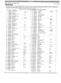
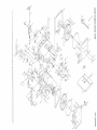
CRAFTS_#A_
" When
- Any
14" ECA_D _qAW
servicing
attempt
technicim_.
use
only
to repair
Repair
CRAF"IFSMAN
or replace
service
137.224240replacement
electrical
is availabl{]
parts
at your
ORDER
Kej!
1
2
3
Part No.
3AD001gl
3ADO()201
3AD00301
Descriplion
Upper frame mm
Lock handle
Nut
4
5
6
7
8
g
3AD00401
3ADOO501
3AD00601
3AD00701
3AD()0801
3AD0OgOl
Guide post
Guide supporl bracket
Sector screw
Upper spacing sleeve
Blade goard
Bearing
3AD01"101
3AD01201
Blade gtrar(I block
Tension knob
13
I4
16
16
17
18
19
3AD01301
3AD01401
3AD01501
3AD01602
3AD01701
3AD01801
3AD61901
Nameplale
Adjust nut
Spring
Sliding bracket
Square nut
Adjnstmenl knob
Shaft hinge
3AD02101
Steel pin
3AD02201
Upper wheel shaft
3AD02301
Bearing
3AD02401
Upper wheel
3AD02501
Tire
STD541050Hex.
nut
3AD02701
Stud
3AD02801
Upper guard inside
3AD02901
Upper guard outside
_30 _3AD93!02 J£nob.......................
31
32
33
34
35
36
37
39
39
3AD03101
3AD03201
STD551075
3AD03401
3AD03501
3AD03601
3AD03701
3ADO3801
3AD03902
Selpin
Hex. bolt
Flat washer
Base
14ex.nut
Blade
]able insert
Table pin
Table
40
41
42
43
3ADO40Ol
3AD0410/
3AD04201
"3AD04301
Special hex. bo/
Trunnion clamp shoe
Trunnion
Hex. screw
44
45
46
47
48
49
3AD0440i
Hex. bolt
3AD04501
Trunnion suppoll brackel
3AD04601
Star knob
STD551025Spring
washer
3AD04802
Set screw
3ADg4901
Hex. bolt
ONLY
Sears
3ADO510I
3AD05201
3AD05301
STD551025
Set screww/I
He_. nut
Hex. bolt
Flat washer
55
56
3AD0550I
3AD05601
t.ower guide support
Setscrew
57
58
59
3AD05701
3AD05801
3AD05gOl
Hinge
Set screw
Plate
Service
!
Qly
1
1
12
'1
1
1
2
1
2
6xl0L
6200ZZ
6x!.o...........
wasl_er
_rio _ #AD#§£0_I Se.t screw wlLwa sl_ej" ............
61 3ADO6101 Power cord storage
parts
create
3/8
5/16"'2"
:__x3jk
..........
6202ZZ
'1/2
318 ...........
may
create
a HAZARD
a HAZ_ARD
unless
repair
or cause
is done
product
by a qualified
damage.
service
Center.
AND
Key
72
73
74
Part No.
3AD07202
3AD07301
3AD07401
75
76
77
70
79
60
3AD07501
3AD07601
3AD07701
STD551031
3ADO7901
3ADOSOOl
PART NUMBER
Description
Set screw
Flatwasher
Plate
' Cord, motor
Stain relief bushing
Power cord & plug
Flatwasher
Flex, screw
Dust chute
4__8_.. :L/Lq_o
a__
£t __.._ .........................
6mm
3116x3/8
f/16x23
QIy
6
2
1
1
2
1
8
2
1
5/-16xl8
1/4x1/4
5_xsx3o
........
_2.
....
4
1
82
83
3AD08201
STD551031
Hex. screw
Flatwasher
t/2x2
112x28
1
2
1
1
1
1
1
84
85
86
87
99
89
90
3AD08402
3AD08501
3AD08601
3AD0870I
3ADO8802
3AD08901
3ADO90O2
Molor
Key
Nut
Adjusl scrwe
Motor pulley
Set screw w/I washer
Swilch
5×5x60
fi/16
6x45
3
3/16 x 3/0
1
1
4
2
1
2
1
5___t__t
.........
_....
__
_____,%&b_o__
ot __]_o_o
!__w_
a_s_h_e
r_................
2
1
2
1
2
1
2
1
1
92
93
94
95
96
97
96
99
t00
3AD09202
3AD09302
3AD0g4Ol
3AD09502
3AD0gBOl
3AD09701
3AD09802
STD541631
3AD10001
V-belt
Switch box
Set screw w/Iwasher.
Flat washer
Se(screww/I
washer
Frame arm cover, lower
Frame arm cover, upper
Nut
Pin
• A-26
3/'16x3/8
3/16x12
3/'16x1/4
5/16 '
3x10
I
I
1
1
2
2
1
1
1
I
1
2 _ I01 .,ZADj0] 0t _ __..r!s..lk..................................
3 ....
4
102 3AD10202
1 " 103 3AD10301
2
164 BAD10401
I
105 3AD10501
1
106 3AD16601
Shaft
Pointer
Scale
NutSet screw w/I washer
5/16
3/16xl/4
1
1
1
4
2.
I
1
1
107 3AD10701
108 3AD10801
109 3AD1090I
Copper washer •
Stud
Set screw w/I washer
3/16xl/2
2
2
2
I/4x5/8
1
2
2.
2
6
110
111
'112
113
1 '14
Miter gauge
Y _£e block
Flatwasher
Knob
Headless screw
5/16x1-1/4
u!" • _,-
2
1
115 3AD11501
118 3ADI '160"1
Spring
Steel ball
"16nrn]
5/16
3/16X2-1/4
5/16x3"
2
6
2
1
"117
118
119
126
Spring
Holder,
Spring
Spring
S: 19 ..........
2__ J!I 3ApJ_2]01__syLr-Jap
- screw................
3/-_613J!.......
]....
3/16x3/8
5116
1/4x3/4
114
2
1
2
2
122
123
124
125
Flatwasher
Blade guard
Clip tread
Set screw
1/4x16
3116x1/4
2
1
2
2
6x10
1
3
126 3AD1260I
127 3AD12701
hex. wrench
Set screw washer
3ram
3/'16x3/8
1
2
2
2
2
'128 3ADI2801
129 STD551031
130 3AD13001
Flatwasher
Flat washer
C-ring
3/16
5/I6
S-2O
2
2
1
311611/4 .......
3x20
_2 ___
1
3/4
3/16x3/8
1
1 ,
4
3/4
_50 _:3_A..Oo£oI
LC-ri!i"........................
other
may
BY MODE[_ NUMBER
3/4x2-1/2
3/4
51
52
53
54
of any
saw
..
_2o__35D9_2o_oj..
Y!! ........................
21
22
23
24
25
26
27
20
29
nearest
Use
band
6/I6x1-1/4
3/'16
_j o__a,L,,
po__O..L
,.s'_js_rew ........................
1'1
12
pads.
on ibis
16" x16"_
10x50
3/16x3/8
11.16x318.......
3ADl1002
3ADl1101
3ADl1201
3ADl1301
3AD11401
3ADl170"1
3A011801
3ADt 1g0"1
3AD12001
STD551025
3ADI2301
3AD12401
3AD12501
washer
brush
washer
plate, connector
L4_ _ 131 3ApJ 31 11 __ Set screw wJl washer ...........
2 132 3AD13201
Spring
62
63
64
3AD06202
3AD06302
3AD06401
Spring washer
Pulley
14ex. screw
3/16"
7"
5/16xlt/4"
16
1
4
133 3AD1330I
134 3AD13401
135 3AD1350I
Spring washer
Set screw
Set screww/I washer
65
66
67
69,
60
70
3AD06501
3ADO660I
3ADO8701
3AD06801
3AD06901
3ADO7001
Snap ring
Bearing
Lower wheel
Hex. screw
Lower door
Guard
R-34
6204ZZ
2
2
1
1
1
1
136
137
138
139
140
14I
Hinge
Spring washer
14ex. nut
Flatwashef
Handle
Pointer
71
3AD67162
Bearing cover
1
142 3ADI420I
143 3AD14301
114x5/8
3AD13601
3AD13701
3AD1380I
3A013901
3AD14001
3AD14101
Flat washer
Set Screw
5/16x5/16
1
2
2
1
1
1/4
1
1
3/16x14
3/16
3/16
3/4"
3/4!!
3/8x25
3116
MBx16L
2
1
16
2
1
1
1
1
1
1
2
1
:: ?
J
{;i
1
< ::1
?i
I
/
58
112
on
103
_55
39
7O
8O
~-
,t:_j
/
€,a
b
©
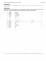
C _AIFTSI_IAIT\_ _AND
SAW
LE(_
When servicing .use 0nly CRAFTSMAN
product
_3L22424
STA_D
replacement parts. Use of any other parts may create a HAZARD or cause
damage.
Any attempt to repair or rep ace electrical paris on _,hisband saw may create a HAZARD unless repair is done by a
qualified
service
technician.
ReP.air
service
is available
at y6ur
nearest
Sears
Service
Center.
1
.-IAD30102
Top Plate
1
2
1AD30202
Tools Tray
1
3
1AD30302
L.H. Side Plate
1
4
1AD30402
R,H. Side Plate
1
5
1AD30502
Back Plate
1
6
1AD30602
Door Plate
1
7
'1AD30702
Magnetic
2
8
1AD30802
g
1AD30902
10
1AD31002
Carriage Screw
11
tAD31102
Hex Nutlw/Washer
12
1AD31202
Hex. Nut
13
1AD31302
Pad
4
14
1AD31402
Hex, Screw
1
15
1AD31502
Spring VTasher
1
16
1AD31602
Knob
"1
17
IAD3'1702
Label
1
Iron Set
Tapping Screw
Set Screw wNVasher
3 xl 2
4
3/16"x3/8"
8
5/16"xl/2"
16
5/16"
3/8
16
4
CRAFTS_'_b_N
BAil[i)
b
I-I
J
SAW
L[::Q STAili]
=Q=o_=- °.=o-=.,_',_