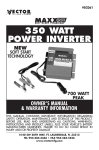
1
OWNER’S GUIDE
INSTALLATION GUIDE
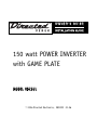
150 watt POWER INVERTER
with GAME PLATE
MODEL VDC301
© 2006 Directed Electronics, N89222 01-06
Table of Contents
Table of Contents . . . . . . . . . . . . . . . . . . . . . . . . . . . . . . . . . .2
Non-Transferable Limited Consumer Warranty . . . . . . . . . . . . . . . .4
Cautions . . . . . . . . . . . . . . . . . . . . . . . . . . . . . . . . . . . . . . . . .6
What’s Included . . . . . . . . . . . . . . . . . . . . . . . . . . . . . . . . . . . .7
Principle of Operation . . . . . . . . . . . . . . . . . . . . . . . . . . . . . . .7
Inverter Output Waveform . . . . . . . . . . . . . . . . . . . . . . . . . . . . .8
Power Source . . . . . . . . . . . . . . . . . . . . . . . . . . . . . . . . . . . . .9
Installation of rubber mounting feet . . . . . . . . . . . . . . . . . . . .10
Placement of Inverter . . . . . . . . . . . . . . . . . . . . . . . . . . . . . . .12
Connecting to Power Source . . . . . . . . . . . . . . . . . . . . . . . . . .13
Electrical Connections . . . . . . . . . . . . . . . . . . . . . . . . . . . . . .14
Temporary Battery Connection..............................................15
Permanent Battery Connection .............................................15
Connection to Load ...........................................................16
Caution: Rechargeable Appliances.........................................17
Game Plate Installation . . . . . . . . . . . . . . . . . . . . . . . . . . . . .18
Mounting the Game Plate ....................................................18
Typical Connection Diagram .................................................19
Fuse Replacement . . . . . . . . . . . . . . . . . . . . . . . . . . . . . . . . .19
Operating Tips . . . . . . . . . . . . . . . . . . . . . . . . . . . . . . . . . . . .20
Rated versus Actual Current Draw of Equipment ......................20
Battery Operating Time .......................................................21
2
© 2006 Directed Electronics - all rights reserved
Caution: Low Battery Alarm .................................................22
Troubleshooting . . . . . . . . . . . . . . . . . . . . . . . . . . . . . . . . . . .23
Automatic Protective Features of the Inverter ........................23
Common Problems . . . . . . . . . . . . . . . . . . . . . . . . . . . . . . . . .24
Troubleshooting Guide . . . . . . . . . . . . . . . . . . . . . . . . . . . . . .25
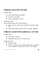
Problem: Lack of power output ............................................25
Problem: Low Output Voltage...............................................27
Problem: Low Battery Alarm On All The Time..........................27
Specifications . . . . . . . . . . . . . . . . . . . . . . . . . . . . . . . . . . . .28
© 2006 Directed Electronics - all rights reserved
3
Non-Transferable Limited Consumer Warranty
Directed Electronics, Inc. (Directed) promises to the original purchaser that the automotive
video monitor and/or source unit(s) (the Product), excluding accessories, purchased and
installed from a Directed authorized dealer within the ninety (90) days after purchase of the
new vehicle, in which the Product is installed, is free from defects in materials or workmanship under normal use and conditions for a period of three (3) years from date of purchase
or the first 36,000 miles as registered on the new vehicle's odometer reading at time of delivery of the Product for warranty service, whichever occurs first. Product purchased or
installed more than ninety (90) days after the new vehicle is purchased are warranted for a
period of one (1) year from date of purchase of the Product.
Directed promises to the original purchaser that all video accessories will be free from
defects in materials and workmanship under normal use and condition for a period of ninety (90) days after the date of purchase. A sales receipt and/or warranty registration card is
required to provide proof of date of purchase of the Product or accessories.
Should the Product be determined defective during the applicable warranty period, the
Product will be repaired or replaced with a new or comparable reconditioned part(s), at
Directed's option. To obtain warranty service, the Product must be returned to a Directed
authorized dealer along with proof of purchase and installation.
Note: This warranty does not cover labor costs for the removal and reinstallation of the
Product. IN ORDER FOR THIS WARRANTY TO BE VALID, YOUR PRODUCT MUST BE
SHIPPED WITH PROOF OF PURCHASE AND INSTALLATION BY AN AUTHORIZED
DIRECTED DEALER. ALL PRODUCTS RECEIVED BY DIRECTED FOR WARRANTY
REPAIR WITHOUT PROOF OF DIRECTED DEALER INSTALLATION WILL BE DENIED.
This warranty is non-transferable and does not apply to any Product that has been modified
or used in a manner contrary to its intended purpose, and does not cover damage to the
Product caused by installation or removal of the Product. This warranty is VOID if the product has been damaged by accident or unreasonable use, negligence, acts of God, neglect,
improper service or other causes not arising out of defect in materials or construction. This
warranty does not cover the elimination of externally generated static or noise, or the correction of antenna problems or weak television reception, damage to tapes, video games,
software, camcorders, discs, speakers, accessories or vehicle electrical systems, cosmetic
damage or damage due to negligence, misuse, abuse, failure to follow operating instruc-
4
© 2006 Directed Electronics - all rights reserved
tions, accidental spills or customer applied cleaners, damage due to environmental causes
such as floods, airborne fallout, chemicals, salt, hail, windstorms, lightning or extreme temperatures, damage due to accidents, road hazards, fire, theft, loss or vandalism, damage
due to improper connection to equipment of another manufacturer, modification of existing
equipment, use of a faulty tape cartridge or cleaning of the VCR head, or Product which has
been opened or tampered with for any reason or which has been damaged due to alteration
or service performed by anyone other than Directed Electronics, Inc.
ALL WARRANTIES INCLUDING BUT NOT LIMITED TO EXPRESS WARRANTY, IMPLIED
WARRANTY, WARRANTY OF MERCHANTABILITY, FITNESS FOR PARTICULAR PURPOSE, AND WARRANTY OF NON-INFRINGEMENT OF INTELLECTUAL PROPERTY
ARE EXPRESSLY EXCLUDED TO THE MAXIMUM EXTENT ALLOWED BY LAW, AND
DIRECTED NEITHER ASSUMES NOR AUTHORIZES ANY PERSON TO ASSUME FOR IT
ANY LIABILITY IN CONNECTION WITH THE SALE OF THE PRODUCT. DIRECTED HAS
ABSOLUTELY NO LIABILITY FOR ANY AND ALL ACTS OF THIRD PARTIES INCLUDING
ITS LICENSED DEALERS OR INSTALLERS. IN NO EVENT WILL DIRECTED ELECTRONICS, INC. BE LIABLE FOR ANY INCIDENTAL, SPECIAL OR CONSEQUENTIAL
DAMAGES (INCLUDING LOSS OF PROFITS), BY PURCHASING THIS PRODUCT, THE
CONSUMER AGREES AND CONSENTS THAT ALL DISPUTES BETWEEN THE CONSUMER AND DIRECTED SHALL BE RESOLVED IN ACCORDANCE WITH CALIFORNIA
LAWS IN SAN DIEGO COUNTY, CALIFORNIA.
Some states do not allow limitation on how long an implied warranty lasts. In such states,
the limitations or exclusions of this Limited Warranty may not apply. Some states do not allow
the exclusion or limitation of incidental or consequential damages. In such states, the exclusion or limitation of this Limited Warranty may not apply to you. This Limited Warranty gives
you specific legal rights, and you may have other rights which vary from state to state.
Some states do not allow the exclusion or limitation of incidental or consequential damages.
In such states, the exclusion or limitations of this Limited Warranty may not apply to you. This
Limited Warranty gives you specific legal rights and you may have other rights which vary
from state to state.
© 2006 Directed Electronics - all rights reserved
5
Cautions
WHEN CONNECTING DIRECTLY TO A BATTERY OR OTHER POWER SOURCE
OBSERVE PROPER POLARITY.
DO NOT EXCEED THE MAXIMUM INPUT VOLTAGE 15 ±0.3 VDC (DIRECT
CURRENT).
ALWAYS DISCONNECT THE INPUT TO THE INVERTER WHEN IT IS NOT IN USE.
REGULARLY CHECK THAT THE INPUT AND OUTPUT CONNECTIONS ARE
TIGHT. LOOSE CONNECTIONS CAN GENERATE HARMFUL HEAT AND/OR
DAMAGE THE INVERTER OR POWER SOURCE.
IMPROPER USE OF THE DEVICE CAN CAUSE DAMAGE OR INJURY AND
EVEN LOSS OF LIFE.
6
© 2006 Directed Electronics - all rights reserved
What’s Included
150W Power Inverter
Game Plate
(4) screws to mount Inverter
Fuse ATC 10 amp
(4) Rubber Feet
(4) screws to mount
Game Plate
(4) screws to mount Rubber
Feet
Principle of Operation
The inverter converts power in two stages. The first stage is a DC to
DC converter, which raises the low voltage DC at the inverter input to
145 volts DC. The second stage is the actual inverter stage. It converts the high voltage DC into 115 volts, 60Hz AC. The inverter stage
uses advanced power MOSFET transistors in a full bridge configuration.
This gives you excellent overload capability and the ability to operate
tough reactive loads.
© 2006 Directed Electronics - all rights reserved
7
Inverter Output Waveform
The AC output waveform of the Inverter is called a "quasi-sine wave"
or a "modified sine wave". It is a stepped waveform that is designed
to have characteristics similar to the sine wave shape of utility power.
A waveform of this type is suitable for a wide variety of applications.
The modified sine wave produced by the Inverter is designed to have
a RMS (root mean square) voltage of 115 volts, the same as standard
household power. Most AC voltmeters (both digital and analog) are
sensitive to the average value of the waveform rather than the RMS
value. They are calibrated for RMS voltage under the assumption that
the waveform measured will be a pure sine wave. These meters will not
read the RMS voltage of a modified sine wave correctly. They will read
about 20 to 30 volts low when measuring the output of the Inverter.
For accurate measurement of the output voltage of the Inverter, a true
RMS reading voltmeter such as a Fluke 87, Fluke 8060A, Beckman
4410, or Triplett 4200 must be used.
8
© 2006 Directed Electronics - all rights reserved
Power Source
The power source must provide between 9.5 and 15 ±0.3 volts DC and
must be able to supply sufficient current to operate the load. The
power source may be a battery or a well regulated DC power supply.
As a rough guideline, divide the power consumption of the load (in
watts) by 12 (the input voltage) to obtain the current (in amperes)
the power source must deliver.
Example: Load is rated at 140 watts.
Power source must be able to deliver: 140/12= 11.66amperes
CAUTION: THE INVERTER MUST BE CONNECTED ONLY TO BATTERIES WITH A NOMINAL OUTPUT
VOLTAGE OF 12 VOLTS. THE INVERTER WILL NOT OPERATE FROM A 6 VOLT BATTERY AND WILL
BE DAMAGED IF IT IS CONNECTED TO A 24 VOLT BATTERY.
© 2006 Directed Electronics - all rights reserved
9
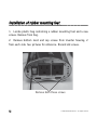
Installation of rubber mounting feet
1. Locate plastic bag containing 4 rubber mounting feet and 4 new
screws. Remove from bag.
2. Remove bottom most end cap screws from inverter housing, 2
from each side. See pictures for reference. Discard old screws.
Remove both these screws
10
© 2006 Directed Electronics - all rights reserved
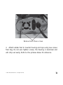
Remove both these screws
3. Attach rubber feet to inverter housing end caps using new screws
from bag. Do not over tighten screws, the housing is aluminum and
will strip out easily. Refer to the pictures below for reference.
© 2006 Directed Electronics - all rights reserved
11
Mount feet on both ends
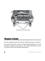
Placement of Inverter
For best operating results, the Inverter should be placed on a flat surface, such as the floor or seat of a vehicle. Approximately 20" of cord
have been provided for this purpose. The inverter should only be used
in locations that meet following requirements:
12
© 2006 Directed Electronics - all rights reserved
DRY - do not allow water to drip or splash on the Inverter.
COOL - ambient air temperature should be between 50 and 80 F. Do
not place the Inverter on or near a heating vent or any piece of equipment, which is generating heat above room temperature. Do not place
the Inverter in direct sunlight.
VENTILATED - allow at least one inch of clearance around the Inverter
for airflow. Do not place items on or over the Inverter during operation. Make sure that air is allowed to circulate freely around the unit.
SAFE - do not use the Inverter near flammable materials or in any
location which may accumulate flammable fumes or gases, such as the
battery compartment of your car, truck, RV or boat.
Connecting to Power Source
Connection can also be made directly to the vehicle’s battery. In that
case a 20 amp ATC fuse can be used (not supplied).
© 2006 Directed Electronics - all rights reserved
13
Electrical Connections
The Inverter comes with a cigarette lighter plug adapter for connection to the power source. The tip of the plug is positive and the side
contact is negative. Connect the plug to the cigarette lighter socket
by pushing in firmly to insure proper contact.
The majority of modern automobiles, RVs, and trucks are negative
ground. Do not use the Inverter with positive ground vehicle electrical systems.
CAUTION: DO NOT USE WITH POSITIVE GROUND VEHICLE SYSTEMS.
CAUTION: CONNECT DIRECTLY TO POWER SOURCE WHEN OPERATING ABOVE 100 WATTS
Most cigarette lighter currents are fused between 10-15 amps. Thus,
connection of the 150W Inverter using the cigarette lighter plug
adapter is suitable for operating the inverter at power outputs up to
approximately 100 watts.
If the inverter is to be used at power levels above 100 watts, direct
connection to the power source is recommended using a hardwire connection.
14
© 2006 Directed Electronics - all rights reserved
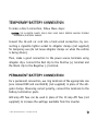
TEMPORARY BATTERY CONNECTION
To make a direct connection, follow these steps:
CAUTION: THE ALLIGATOR CLAMPS COULD COME LOOSE WHILE DRIVING CAUSING POSSIBLE
MECHANICAL/ELECTRICAL DAMAGE.
Convert the 12-volt car cord into a hard wired connection, by connecting a cigarette lighter socket to alligator clamps (not supplied)
for temporary use (do not leave alligator clamps on when the vehicle
is being driven).
Then, make a good connection to the power source terminals using
alligator clips. Connect the Red clip to the Positive (+) terminal and
the Black clip to the Negative (-) terminal.
PERMANENT BATTERY CONNECTION
For a permanent connection, use ring terminals of the appropriate size
(one colored RED and one BLACK) (not supplied) in place of the alligator clamps. Observing correct polarity, connect the terminals to the
battery termination posts.
A20 amp ATC fuse can be used in place of the 10 amp ATC fuse (not
supplied) to increase the wattage available from the inverter.
© 2006 Directed Electronics - all rights reserved
15
CONNECTION TO LOAD
Once you have determined the proper method of connection to the
power source (cigarette lighter or direct to battery with adapter socket), connect the 150W Inverter accordingly, making sure to fully insert
the plug into the appropriate socket. Now plug appliance(s) into the
receptacle(s) on the Inverter and flip the rocker switch to the (ON)
position. The green LED above it and slightly to the right will illuminate. Turn on your appliance(s) making sure the load requirements are
within the parameters of the Inverter's output
If an audible alarm sounds, that means the power input voltage is too low.
At 9.5V, the PROT (protection) indicator LED will illuminate to red and
the inverter will automatically shut down.
CAUTION: DO NOT CONNECT TO AC DISTRIBUTION WIRING
The Inverter is designed to be directly connected to standard electrical and electronic equipment in the fashion described above. Do not
connect the Inverter to household or RV AC distribution wiring. Do
not connect the Inverter to any AC load circuit in which the neutral
conductor is connected to ground or to the negative of the DC (battery) source.
16
© 2006 Directed Electronics - all rights reserved
CAUTION: RECHARGEABLE APPLIANCES
Certain rechargeable devices are designed to be plugged directly into
an AC receptacle to be recharged. These devices may damage the
Inverter. When first using a rechargeable device monitor its temperature for the first 10 minutes to ensure that it does not become abnormally hot. That will be your indication that it should not be used with
this inverter.
This problem does not occur with the vast majority of battery operated equipment. Most equipment of this type uses a separate charger or
transformer that is plugged into the AC receptacle. The Inverter
should have no trouble powering these chargers and transformers.
© 2006 Directed Electronics - all rights reserved
17
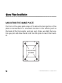
Game Plate Installation
MOUNTING THE GAME PLATE
The front of the game plate snaps off to allow the back portion of the
plate to be mounted in a convenient location in the vehicle (such as
the back of the front-center seat arm rest). Make sure that the location you pick will allow the AC cord from the plate to reach the inverter.
4-MOUNTING
SCREWS
18
© 2006 Directed Electronics - all rights reserved
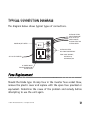
TYPICAL CONNECTION DIAGRAM
The diagram below shows typical types of connections.
L
POWER ON/OFF SWITCH
OFF
ON
AUDIO AND VIDEO
CABLES FROM GAME
PLATE TO AN A/V
SWITCH BOX OR
AUXILARY INPUT ON
A VIDEO SCREEN
AUDIO
VIDEO GAME
AUDIO AND VIDEO
RCA PHONE CONNECTIONS
R
AC PLUG TO INVERTER
110V AC
VIDEO
FROM: GAME CONSOLE,
OR PMP3520,
OR DMP040/070
AC POWER SOCKET
FOR GAME CONSOLE OR
OTHER DEVICE
Fuse Replacement
Should the blade type 10-amp fuse in the inverter fuse socket blow,
remove the plastic cover and replace with the spare fuse provided or
equivalent. Determine the cause of the problem and remedy before
attempting to use the unit again.
© 2006 Directed Electronics - all rights reserved
19
Operating Tips
RATED VERSUS ACTUAL CURRENT DRAW OF EQUIPMENT
Most electrical tools, appliances and audio/video equipment have a
label indicating power consumption in amps or watts. Add up the
power consumption of those items you will be using simultaneously,
keeping the total below the rating of Inverter. If the power consumption is rated in amps, multiply by the AC voltage (115) to determine
the wattage. For example, a power drill rated at 3.2 amps will draw
368 watts, more than the 150W Inverter can handle on a continuous
basis.
Resistive loads are the easiest for the Inverter to drive, though larger resistive loads, such as electric stoves or heaters, usually require
more wattage than the Inverter can deliver continuously. Inductive
loads, such as TV 's and stereos (any device with a coil or transformer
in it), by nature require more current to operate than a resistive load
of the same wattage rating. Induction motors (motors without brushes), as well as some televisions, may require 2 to 6 times their
wattage rating to start up. This condition may require repeated "ON
OFF, ON OFF, ON OFF" switching of the power switch on your Inverter
in order to get them "started".
20
© 2006 Directed Electronics - all rights reserved
The most demanding are those that start under load, i.e. compressors and pumps. Since motor and television characteristics vary
widely, only testing will determine if a specific load can be started
and how long it can be run. There are no standards for "surge power"
partly because this specification cannot be represented accurately
by a simple number.
Though the 150W Inverter can provide power up to 175 watts on a
momentary basis, experimentation is the only means of determining
whether it can handle the surges needed to start a particular load.
IMPORTANT NOTE: The 150W Inverter will not operate most appliances designed to produce
heat, such as hair dryers, coffee makers, irons, heaters, and toasters. The current draw of most
of these exceeds 1000 watts, far beyond the capacity of this unit.
BATTERY OPERATING TIME
With a typical vehicle battery, a minimum operating time of 1 to 2
hours can be expected between recharging, depending on the current
draw of the load being driven. We recommend that the operator start
the vehicle every hour to recharge the battery system. This will prevent any unexpected shutdowns of the equipment and will ensure that
there is always sufficient battery capacity to start the vehicle engine.
© 2006 Directed Electronics - all rights reserved
21
The inverter may be used either while the engine is running or turned
off. However, the Inverter may not operate while the engine is being
started since the battery voltage can drop substantially during cranking.
The Inverter draws less than 0.2 amperes from the battery when it is
not supplying power to a load. In most cases the 150W Inverter may
be left connected to the battery for up to 3 hours when it is not in
use since it draws so little current. If the vehicle will not be used for
several days, disconnect the Inverter from the battery.
CAUTION: LOW BATTERY ALARM
An alarm will sound when the voltage from the battery drops to 10.2
volts. This indicates that the battery requires recharging. The user
should stop operations at this time since the Inverter AC will shut
down automatically shortly afterwards (when battery voltage drops to
9.5 volts)
NOTE: The alarm may sound momentarily when the unit is being connected to, or disconnected from, the power source. This is normal and does not indicate any problem.
22
© 2006 Directed Electronics - all rights reserved
Troubleshooting
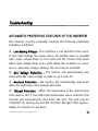
AUTOMATIC PROTECTIVE FEATURES OF THE INVERTER
Your Inverter circuitry constantly monitors the following potentially
hazardous conditions:
a) Low Battery Voltage - This condition is not harmful to the inverter but could damage the power source. An audible alarm is sounded
when input voltage drops to 10.2 volts and the inverter shut down
when input voltage drops to 9.5 volts. When the condition is corrected (i.e. alternator charges battery) the unit may be restarted.
b) Over Voltage Protection - The inverter will automatically shut
down when the input voltage exceeds 15 ±0.3 volts DC.
c) Overload Protection - the inverter will automatically shut down
when the continuous draw exceeds 300 watts.
d) Thermal Protection - When the temperature of the internal heat
sinks reaches 150°F, the solid-state temperature sensor located in the
inverter will automatically shut down the unit. The unit may be
"restarted" by turning the unit OFF and then ON again after approximately 15 minutes of cool down.
© 2006 Directed Electronics - all rights reserved
23
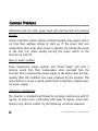
Common Problems
Televisions will not start, power tools will start but will not continue
to run.
Certain induction motors (motors without brushes) may require two to
six time their wattage ratings to start up. If the power tool runs
momentarily then stops when power is applied, try leaving the power
to the tool "on" while quickly turning the power switch on the
Inverter on and off.
Buzz in audio systems
Some inexpensive stereo systems and "boom boxes” will emit a
buzzing sound from their loudspeakers when operated from the
Inverter. This is because the power supply in the device does not adequately filter the modified sine wave produced by the Inverter. The
only solution is to use a sound system that incorporates a higher quality power supply.
Television interference
The Inverter is shielded and filtered to minimize interference with TV
signals. In some cases, particularly with weak TV signals, some interference may still be visible. Try the following corrective measures:
24
© 2006 Directed Electronics - all rights reserved
a) Position the Inverter as far as possible from the television, the
antenna and the antenna cables.
b) Adjust the orientation of the Inverter, the antenna cables, and
the TV power cord to minimize interference.
c) Make sure that the antenna feeding the television provides an
adequate ("snow free") signal and that high quality, shielded antenna
cable is used.
Troubleshooting Guide
PROBLEM: LACK OF POWER OUTPUT
Possible causes
Inverter not adequately warmed up
Automotive system requires ignition to be on
Battery voltage below 9.5 volts
Equipment being operated draws too much power
Inverter in thermal shutdown condition
© 2006 Directed Electronics - all rights reserved
25
The alligator clips of the hard wire adapter are connected
incorrectly to the battery terminals.
Suggested remedy
Some types of loads will not allow the inverter to turn on.
These type of loads are inductive (an example would be a
fan). Turn the Inverter power switch off and unplug the
load(s) from the inverter then turn the inverter On. Now connect the load(s).
Turn Inverter power switch off and then on again until the
Inverter powers your appliance. Repeat as necessary to get
your appliance "started".
Turn ignition to accessory position.
Recharge or replace battery.
Reduce load to maximum 100 watts.
Allow Inverter to cool down. Ensure there is ventilation
around unit. Ensure that load is no more than 100 watts for
continuous operation.
Replace fuse with a new 10 Amp fuse (blade type), then
ensure that the red clip is connected to the positive terminal and the black clip to the negative terminal.
26
© 2006 Directed Electronics - all rights reserved
PROBLEM: LOW OUTPUT VOLTAGE
Possible causes
Using average-reading voltmeter.
Inverter is overloaded.
Input voltage below 9.5 volts.
Suggested remedy
Use true RMS reading meter for the following:
Reduce load to a maximum of 100 watts to maintain regulation.
Keep input voltage above 9.5 volts to maintain regulation.
PROBLEM: LOW BATTERY ALARM ON ALL THE TIME
Possible causes
Poor battery condition.
Inadequate input power or excessive load.
Suggested remedy
Replace battery.
Check the voltage at the cigarette lighter plug and socket.
Clean or replace as necessary to correct for low voltage.
© 2006 Directed Electronics - all rights reserved
27
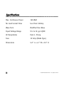
Specifications
Max. Continuous Power
150 Watt
No Load Current Draw
less than 0.2Amp
Wave form
Modified Sine Wave
Input Voltage Range
9.5 to 15 (±0.3)VDC
AC Receptacles
Dual 3 -Prong
Fuse
10 Amp (Blade Type)
Dimensions
5.2" L x 4.1" W x 2.2" H
28
© 2006 Directed Electronics - all rights reserved
© 2006 Directed Electronics - all rights reserved
29
The company behind this system is Directed Electronics.
Since its inception, Directed has had one purpose, to provide consumers with the finest vehicle security, car stereo products, rear seat entertainment, and accessories available. The recipient of more
than 20 patents in the field of advanced electronic technology, Directed is ISO 9001 registered.
Quality Directed Electronics products are sold and serviced throughout North America and around the
world.
Call (800) 274-0200 for more information about our products and services.
Directed® is committed to delivering world-class quality products
and services that excite and delight our customers.
Directed Electronics
Vista, CA 92081
www.directed.com
© 2006 Directed Electronics—All rights reserved
N89222 01-06