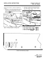
1
Print Vendor
Instructions
Paper Size:
How to use this file
Operator’s Manuals
• 11x17
• Body - 50 lbs brilliant white offset or equivalent
• Cover - on pre-printed two tone “Swash” stock.
Press:
• Body - 1 color, 2-sided
• Cover - 1 color, 1 sided
Bindery:
• Saddle stitch, face trim
*if too thick for saddle stitch, tape bind
Covers:
• FRONT COVER is present at the beginning of the file.
• BACK COVER is the page immediately after the front cover.
• The part number for this manual (typically a 172_____ number) is
located on the front cover.
• This file may contain several manual which differ only by their covers.
See the part number at the bottom of the cover page. .
Body:
• The body for all manuals is identical regardless of the cover.
• Odd number pages are always right hand pages, even number pages
are always left hand pages.
General:
• This instruction sheet is NOT part of the manual and must not be
printed.
• Pages labeled “THIS PAGE INTENSIONALLY BLANK” are placement
pages and should NOT be printed.
THIS PAGE INTENTIONALLY BLANK
(FOR PLACEMENT ONLY - DO NOT PRINT)
OPERATOR’S
MANUAL
Clean Sweep
Twin Catcher
Clean Sweep Twin Catchers
Mfg. No.
1692149
1692150
Description
Clean Sweep Twin Catcher (for 30” Mower Decks)
Clean Sweep Twin Catcher (for 34” Mower Decks)
1709142-08
Rev 04/2004
TP 100-2181-08-AT-UV
MANUFACTURING, INC.
500 N Spring Street / PO Box 997
Port Washington, WI 53074-0997
www.simplicitymfg.com
© Copyright 2004 Simplicity Manufacturing, Inc.
All Rights Reserved. Printed in USA.
Table of Contents
Safety Rules & Information
General Warnings............................................2
Safety Decals ..................................................2
General Operating Instructions
Mowing with the Catcher .................................3
Required Accessories......................................3
After Operation ................................................3
Operation & Storage
Before Operation .............................................4
Operation.........................................................4
Emptying the Bags ..........................................4
Storage ............................................................4
Normal Installation & Removal
Installation & Removal .....................................5
Troubleshooting
Chart................................................................7
Initial Setup & Assembly
30” Models - Blade and Adapter Assembly .....8
34” Models - Baffle, Blade, & Adapter Assy...10
Frame & Bagger Support Assy. - All ..............12
Grass Catcher Assy. - All...............................13
Supplemental Kit Instructions
Baffle Kit Instructions.....................................16
Heat Shield Kit Instructions ...........................17
Hardware Identification & Torque
Chart..............................................................18
1
Safety Rules
& Information
Read these safety rules and follow them closely. Failure to obey these rules could result in loss of control of
unit, severe personal injury or death to you, or bystanders, or damage to property or equipment. The triangle
in text signifies important cautions or warnings which must be followed.
GENERAL WARNINGS
• Know the unit’s controls and how to stop quickly.
READ THE OPERATOR’S MANUALS.
• Read and obey all safety decals.
• Only allow responsible adults, who are familiar with
the instructions, to operate the unit.
• Disengage the PTO. Shut off the engine and wait for
all moving parts to stop before attaching, adjusting,
or disconnecting any part of the collection system.
• Check the collection system to make sure it is bolted
tightly to the unit.
• DO NOT operate the unit without either the entire
grass catcher or the deflector in place.
• Turn off the PTO to disengage the blades when not
mowing.
• DO NOT mow in reverse. Always look down and
behind before and while travelling in reverse.
• DO NOT turn sharply when travelling alongside a
building or any object. Slow down before turning.
• DO NOT carry passengers.
• When collection system is removed from the mower
deck, the deflector must be properly installed.
• Collector bags are subject to deterioration and wear
during normal use. Inspect the bag periodically for
tears, holes, or weak spots and replace with a new
bag that meets manufacturer’s durability standards.
• If the mower stalls or the collector chute plugs:
1. Disengage the PTO;
2. Stop the engine and remove the key;
3. Set the parking brake, and wait for all moving
parts to stop.
4. Remove the foreign object or clear the chute
with a piece of wood before restarting the engine.
NEVER place hands into COLLECTOR OR
MOWER housing to clear jammed objectS.
Blower OR MOWER may rotate when object is
removed.
• For added stability and to prevent tipping or loss of
control:
a. Use reduced speed on uneven ground and
when turning corners.
b. Reduce loads on hillsides. It is recommended
that the collection system be kept only half full
when negotiating any slopes. Start mowing on
slopes when the collection system is empty.
c. Mow up and down the face of slopes; never
across the face of any slope.
• When operating on slopes, use front counterweights. Never operate on slopes greater than
17.6% (10°).
SAFETY DECALS
These labels are easily applied and will act as a constant
visual reminder to you, and others who may use the
equipment, to follow the safety instructions necessary for
safe, effective operation.
This unit has been designed and manufactured to provide you with the safety and reliability you would expect
from an industry leader in outdoor power equipment
manufacturing.
ATTACHMENT DECALS
Although reading this manual and the safety instructions
it contains will provide you with the necessary basic
knowledge to operate this equipment safely and effectively, we have placed several safety labels on the unit to
remind you of this important information while you are
operating your unit.
WARNING
• Do not open cover with engine running.
• Do not operate mower without the
complete catcher in place
• When operating on slopes, refer to
operator's manual for counterweights.
All DANGER, WARNING, CAUTION and instructional
messages on your rider, attachments and mower should
be carefully read and obeyed. Personal bodily injury can
result when these instructions are not followed. The
information is for your safety and it is important! The
safety decals below are on your product.
1704405
DANGER
DANGER
ROTATING
BLADES
ROTATING CUTTING BLADE
DO NOT OPERATE MOWER
WITHOUT DEFLECTOR
OR ENTIRE GRASS
CATCHER IN PLACE
If any decals are lost or damaged, replace them at once.
See your local dealer for replacements.
SHUT OFF MOWER
AND TRACTOR
BEFORE SERVICING
OR CLEANING BLOWER
AND MOWER.
1700259
Read and obey all operation and warning decals.
TP 600-2562-01-AT-SMA
2
General
Operating Instructions
BEFORE OPERATION
Clear the lawn of all sticks, stones, wire and other debris
which may be caught or thrown by the mower blades.
Check grass condition. If wet, wait until later in the day.
If grass is wet, the grass catcher is likely to become
plugged.
For efficient bagging, air circulation under the
mower deck, through the chute and into the bag is
very important.
For this reason, BEFORE YOU BEGIN MOWING you
should make certain the underside of the mower and
the underside of the catcher lid are free from grass and
debris.
Make sure that there is a snug fit between mower deck,
blower housing, tubes, and grass catcher cover.
MOWING WITH THE CATCHER
REQUIRED ACCESSORIES
Always operate with throttle at full speed when mowing.
A front-mounted weight carrier and approved weights are
required when using this rear-mounted grass catcher.
Never operate on slopes greater than 17.6% (10°).
Grass should be cut often, and not too short. If grass is
too long or lush it may be necessary to keep ground
speed to a minimum or to cut only half the width of the
mower to prevent clogging. If grass is long, operate with
mower in high cutting position for first pass, cutting again
in a lower position on a second pass.
AFTER OPERATION
Remove any debris from the the screen on the underside
of the lid. Note: The lid screen can be partially removed
for easier cleaning and should be cleaned regularly.
Do not open the cover with mower engaged.
The blower housing and tube should be removed for
cleaning.
If a large amount of cut grass is spilling out from under
deck, the tube may be plugged or the bags may be full—
discontinue mowing, stop the rider, disengage the PTO,
shut off the engine and then empty the catcher or clear
the tube.
Inspect the grass bags for wear or damage. Make sure
that there is a snug fit between mower deck, blower
housing, tubes, and grass catcher cover.
STORING THE GRASS CATCHER
WARNING
Clean the grass catcher thoroughly using a mild detergent (other products may damage the tube). Remove
any debris from the the screen on the underside of the
lid.
ALWAYS shut off the tractor. Disengage the PTO,
and allow all moving parts to stop BEFORE
disconnecting or clearing tube, or emptying
catcher.
If paint has been scratched on metal parts, touch up with
paint, or apply a thin film of oil to prevent corrosion.
Before leaving the operator’s position for any
reason, engage the parking brake, disengage the
PTO, stop the engine and remove the key.
Store in a dry area. Dry thoroughly before storing for a
long period of time. Always store away from moisture.
To reduce fire hazard, keep the engine, rider and
mower free of grass, leaves and excess grease.
Do not stop or park rider over dry leaves, grass or
combustible materials.
3
Operation &
Storage
OPERATION
WARNING
Grass should be cut often, and not too short. If grass is
too long or lush, it may be necessary to keep ground
speed to a minimum or to cut only half the width to prevent clogging. If grass is high, operate with mower in
high cutting position. Cut the grass again in lower cutting
position, if desired.
For safety reasons grass and debris are to be
removed from tube and adapter only after engine
is shut off, key removed and all moving parts
stopped.
WARNING
To check if grass is flowing up tube, view tube through
rear inspection window. Do not open cover with mower
engaged.
Before raising bagger cover, shut off engine,
remove key and set parking brake.
To check if grass bags are full, reach back and feel top
of right bag (left bag will fill first) or view tube through
front inspection window.
BEFORE OPERATION
Clear the lawn of all sticks, stones, wire and other debris,
which may be caught or thrown by the mower blades.
If a large amount of cut grass is spilling out from under
deck, the tube may be plugged or grass bags are full.
Shut off rider, disengage PTO and allow all moving parts
to stop before disconnecting tube.
Clean the tube with mild detergent (other products may
damage tube). Inspection windows can be removed to be
cleaned. Make sure windows are securely in place before
operating.
NOTE: If mower deck is equipped with Mulching Kit, the
mulching baffles must be removed for grass collection.
Make sure the high-lift blades (packaged with the Grass
Bagger Kit) are installed (See Assembly Instructions at
the back of this manual). Standard low-lift blades are recommended for mulching operation.
Check grass condition. If wet, wait until later in the day. If
grass is wet, plugging may occur.
For efficient bagging, air circulation under the mower
deck, through the chute and into the bag is very important. For this reason, you should remove grass and
debris from underside of mower deck, discharge chute
and screen inside cover.
Always operate with throttle at full speed.
EMPTYING THE BAGS
The adapter and tube should be removed for cleaning.
Unhook the wire form and remove the tube from the
adapter. Loosen the wing nut securing the adapter to
mower deck.
Raise the bagger cover. If a plastic liner was not used,
unhook the bag and turn upside down to empty (use
handle on bottom).
If plastic liner was used, first tie top of liner closed. Then,
either pull the liner out, or turn the bag upside down and
allow the filled liner to slide out.
If desired, the bags can be lined with 30-gallon trash
bags for easy disposal.
Inspect the grass bags for wear or damage. Make sure
that there is a snug fit between mower deck, adapter,
tubes and grass bag cover.
STORAGE
Clean the grass catcher thoroughly.
If paint has been scratched on metal parts, coat with
paint or oil.
Store in a dry area. Hang the bags to dry. Always store
away from moisture.
4
Normal Installation &
Removal
INSTALLATION & REMOVAL
NOTE: For first-time installation, refer to Initial Setup &
Installation.
NOTE: If mower deck is equipped with Mulching Kit, the
mulching baffles must be removed for grass collection.
Make sure the high-lift blades (34') or high-lift tabs (30')
are installed per the Assembly Instructions at the back of
this manual.
1. Install the grass bag and bracket assembly (A, figure
1) on the anchor assemblies (B) located on each side
of the transmission housing. Push forward so the
bracket assembly rests fully on the anchors.
2. Insert the round pin (C) through the bracket assembly
and frame, and secure it using the safety clip pin (D).
NOTE: If grass bag and bracket assembly is too bulky to
install as one piece, separate the grass bag cover (A, figure 2) from the upright support (B) by removing clips (D)
and long clevis pins (C). Reinstall cover after support
assembly is properly installed.
5
Normal Installation & Removal
Figure 3.
A. Grass Bag Frame
B. Support Bracket
Figure 4. (30” Mower Shown)
A. Adapter
B. Wing Nut
C. Deflector
D. Jam nut, 5/16-18
E. 1/2” Hole
3. Open grass bag cover and install grass bag frames
(A, figure 3) to support brackets (B).
4. On 30" mower, lift the deflector (C) up and install the
adapter (A, figure 4) to mower deck by hooking
bracket over the rear carriage bolt and securing with
jam nut (D) and positioning front slot on the adapter
under wing nut (B). Secure by tightening knob and
wing nut. Make sure that bottom of adapter is below
stone guard.
On 34" mower, lift up deflector (C) and install the
adapter by hooking rear bracket over the mower
hinge rod and positioning front slot on the adapter
under wing nut (B). Tighten wing nut. Make sure that
bottom of adapter is below stone guard.
5. Apply dry talc to rubber seal at cover opening. Install
tube (A, figure 5) as far as possible into opening to
clear adapter and install over adapter. Secure by
rotating wire form (B) down into locked position over
puck on adapter.
6. To remove the grass catcher assembly, reverse
steps 1 - 5. Make sure deflector (C, Figure 4) is in
proper operating position after removal of grass
catcher adapter.
6
Troubleshooting
The following table provides troubleshooting instructions
for the more common and easily corrected problems. For
problems not covered in the table, see your dealer.
WARNING
To avoid serious Injury, perform maintenance on
the grass catcher only after stopping the engine
and waiting for all moving parts to come to a
complete stop. Always remove the ignition key
before beginning the maintenance to prevent
accidental starting of the engine. Disconnect the
spark plug wire and fasten away from plug.
Problem
Cause/Solution
1. Leaves and grass not being completely
picked up.
A. Engine speed too slow. Run at full throttle.
B. Ground speed too fast. Use lower speed.
C. Discharge tube plugged. Stop engine and remove key. Then
remove and unplug discharge tube.
D. Using wrong mower blades. See Assy. Instructions.
E. Blades not tight. Torque to 60 ft. lbs.
F. Mower not level. See rider Operators Manual to level.
G. Belt or clutch slipping. See rider Operator's Manual for adjustment.
2. Grass catcher discharge tube or
mower plugs easily.
A. Bags full. Empty bags.
B. Grass too high. Reduce rider ground speed, reduce cutting width
or raise mower adjustment for the first pass, lower it for the second pass.
C. Grass or leaves too wet. Wait for drier conditions.
D. Build-up of cut grass in mower or adapter. Clean thoroughly.
E. Screen in grass bag cover clogged. Remove cover and clean
screens.
F. Using wrong mower blades. See Assy. instructions.
G. Belt or clutch slipping. See rider Operator's Manual for adjustment.
H. Cutting off too much grass. High-lift blades and adapter collect
best when 1-1/2" above ground.
I. Engine not running at full throttle. Use transmission lever to control ground speed and keep engine at full throttle.
Table 1. Troubleshooting
7
Initial Setup & Assembly
30” MODELS BLADE AND ADAPTER ASSEMBLY
Blade Assembly - 30” Mower
1. Remove the mower deck to access the blade or
using an overhead hoist, elevate the front of the unit
to access the mower blade.
2. Mount the lifts (B, Figure 6) to the discharge side of
the blade as shown. Torque nuts to 14 ft. lbs.
Adapter & Mounting Hardware Installation 30” Mower
D
C
1. Install reinforcement strap (A, figure 7) inside the
adapter and secure it to the top outer holes using two
10-24 x 5/8" flat head screws (B), flat washers (C)
and 10-24 nuts (D). Be sure the cut-off bracket (G) is
installed between the reinforcement plate (A) and
adapter.
D
A
C
2. In rear hole of mower deck, install 5/16-18 x 1-1/4
carriage bolt (E) from the bottom and secure with
5/16" jam nut (F).
A
F
B
E
Figure 7.
A. Reinforcement Plate
B. Flathead Screw, 10-1/4 x 5*8
C. Flat Washer
D. Nut
E. Carriage Bolt, 5/16-18 x 1-1/4
F. Jam But, 5/16-18
G. Cut-Off Bracket
8
Initial Setup - 30” Models
E
A
C
D
E
1/4"
B
Drill 1/2" Hole
1"
Figure 8.
A. Carriage Bolt, 5/16-18 x 2-1/4
B. Cup
C. Whiz Flange Nut, 5/16
D. Wing Nut
E. Centerlock Nut, 5/16
E
Figure 9. (30” Mower Shown)
A. Adapter
B. Wing Nut
C. Deflector
D. Jam nut, 5/16-18
E. 1/2” Hole
3. Install 5/16-18 x 2-1/4 carriage bolt (A, figure 8)
through front hole in mower deck along with cup (B),
whiz flange nut (C), wing nut (D) and center lock nut
(E). Nut (C) must be seated inside cup and center
lock nut (E) should be flush with end of carriage bolt.
4. Place adapter over rear carriage bolt (A, figure 9) and
position front slot of adapter between mower deck
and wing nut (B). Install jam nut (C) on carriage bolt.
Securely tighten both jam nut and wing nut.
5. Go to FRAME AND BAGGER SUPPORT ASSEMBLY - ALL MODELS to continue assembly procedures.
9
Initial Setup - 34” Models
34" MODELS BAFFLE, BLADE, & ADAPTER
ASSEMBLY
E
I
D
H
K
G
B
H
Install Baffle
F
C
1. Remove mower deck from rider. Position mower deck
upright and support in this position.
J
A
2. Position baffle with notched end towards discharge
side opening, Install all hardware as shown in figure
10. The notch must be positioned to clear the stone
guard weldment.
M
L
3. Tighten all hardware at the discharge side of baffle
first, then tighten hardware at the middle of baffle,
and finally tighten hardware at inside location.
Figure 10. Install Baffle - 34” Models
A. Carriage Bolt, 5/16-18 x 2-1/4
B. Cup
C. Flange Nut, 5/16
D. Wingnut Assy.
E. Centerlock Nut, 5/16
F. Carriage Bolt, 5/16-18 x 1-3/4
G. Spacer (Between Baffle & Deck)
H. Lockwasher, 5/16
I. Nut, 5/16
J. Carriage Bolt, 5/16-18 x 3/4
K. Nut, 5/16
L. Blade Tabs
M. High-Lift Blade
Install Blades Later Models with Hex Arbor
1. Remove existing discharge-side blade but retain
hardware.
2. Install the new high-lift blade (D, figure 11a) with the
tabs pointing up toward the bottom of the deck.
Secure with original hardware and torque capscrew
(H) to 45-55 ft. lbs. (61-75 N.m.).
NOTE: Discard the 2" O.D. splined adapter provided with
the bagger; it is not used with later model decks.
Figure 11a. Install High-Lift Blade - Later Models
A. Washer
E. Blade, 16-1/8”
B. Arbor Shaft
F. Hex Washer
C. Grass Shield
G. Spring Washer
D. High-Lift Blade
H. Capscrew
10
Initial Setup - 34” Models
Install Blades Early Models with Splined Arbor
1. Remove existing discharge-side blade but retain
hardware. Remove the retaining band (E, figure 11 b)
from the arbor shaft and remove the existing splined
adapter (3-3/8" O.D. F, figure 11b). This adapter can
be discarded. The new 2" O.D. splined adapter supplied with the bagger can be used with regular or
high-lift blades. Install the new 2" splined adapter with
existing retaining band (E).
2. Install the new high-lift blade (D, figure 11 b) with the
tabs pointing up toward the bottom of the deck.
Secure with existing hardware (A, B, & C, figure 11b)
and torque capscrew to 50-70 ft. lbs. (66-76 N.m.).
NOTE: After complete assembly of collection system,
test run mower to make sure blades do not contact baffle.
Figure 11b. Install High-Lift Blade - Early Models
A. Capscrew, 7/16-14 x 1
E. Retaining Band
B. Spring Washer
F. Splined Arbor
C. Spline Washer
G. Grass Shield
D. Blade
Adapter Installation
1. Place adapter over rear carriage bolt (A, figure 12)
and position front slot of adapter between mower
deck and wing nut (B). Install jam nut (C) on carriage
bolt. Securely tighten both jam nut and wing nut.
2. Go to FRAME AND BAGGER SUPPORT ASSEMBLY - ALL MODELS to continue assembly procedures.
Figure 12.
A. Carriage Bolt
B. Wing Nut
C. Jam Nut, 5/16-18
11
Initial Setup - All Models
FRAME & BAGGER SUPPORT
ASSEMBLY - ALL MODELS
H
Note: Units with 0510 transmissions use anchors (A, figure 13) with a notch, all other units use anchor with no
notch. See Inset Figure 13.
D
F
1. Assemble the two anchors (A, figure 13) to the transmission housing using the 5/16-18 x 3 capscrews (B),
washers (C) and nuts (E). Install the capscrews from
the bottom of transmission. Do not tighten hardware
at this time.
E
A
2. Position support assembly (F, figure 13) on anchors
and secure to rider with safety clip pin (G) and round
pin (D).
G
3. Fully seat each anchor into the support assembly
tubes and square up bagger frame with rider frame.
Tighten anchor mounting hardware securely.
C
4. Place catcher support (H) into support assembly as
shown (figure 13).
B
0510 Transmssion
Models
(Notch)
Figure 13.
A. Anchor
B. Capscrew, 5/16-18 x 3
C. Flat Washer, 5/16
D. Round Pin
E. Nut, Flange Lock, 5/16
F. Support Assembly
G. Safety Clip Pin
H. Catcher Support
12
All Other
Models
(No Notch)
Initial Setup - All Models
GRASS CATCHER ASSEMBLY ALL MODELS
NOTE: Cover and bag support are packaged as an
assembly with long clevis pins and clips. It may be easier
to separate components for the following step.
1. Install horizontal bag support (A, figure 14) to upright
catcher support (B) holes as shown. Note that the
open set of holes (D) is toward the discharge side of
mower. Install four 3/8-16 x 7/8 capscrews (C) from
the front and lightly secure with flange lock nuts.
2. Make sure bag support and catcher support are
square, then tighten flange lock nuts.
Figure 14.
A. Bag Support
B. Catcher Support
C. Capscrew, 5/16-18 x 7/8
D. Open Set Of Holes
3. Reinstall grass catcher cover (A, figure 15) to support
(B) and secure with clevis pins (C) and clips (D).
Figure 15.
A. Cover
B. Support
4. Install handle (A, figure 16) to rear surface of lid with
offset toward the rear. Secure with two 10-32 x 1/2
truss screws (B) and 10-32 hex nuts (C).
Figure 16.
A. Handle
B. Truss Screw
C. Hex Nut, 10-32
13
C. Clevis Pin
D. Clip
Initial Setup - All Models
5. Open cover and fasten cable (A, figure 17) to tube
support (B) to prevent cover from going over center
when opened. Loop end of cable fits over washer (C).
Figure 17.
A. Cable
B. Support
C. Washer
6. Open grass bag cover and install grass bag frames
(A, figure 18) to support brackets (B). Make sure
cover handle latches to grass bag frames.
Figure 18.
A. Grass Bag Frame
B. Support Frame
14
Initial Setup - All Models
7. Apply dry talc powder to rubber seal at cover opening. Install tube (A, figure 19) as far as possible into
opening to clear adapter and install over adapter.
Figure 19.
A. Tube
B. Wire Form Location
8. Secure tube by moving wire form (A, figure 20) down
over round cup (B) on adapter surface.
Figure 20.
A. Wire Form
B. Round Cup
15
Installation
Instructions
Baffle Kit
Part No. 1686783
For Coronet / 400 / 2400 Series Riders
D
A
C
B
Figure 1. Installation
This kit adds a baffle to twin bag grass catchers
installed on Coronet / 400 / 2400 series riders.
Kit Contents:
Part No.
1720375
Qty.
1
Description
Baffle
INSTALLATION
WARNING
Before beginning any service work turn off the
PTO, set the parking brake, turn off the ignition,
and disconnect the spark plug wire(s).
1. Remove the hardware (D) securing the plastic elbow
(C) to the metal support plate (B).
2. Insert the baffle (A) in between the support plate (B)
and elbow (C).
3. Reinstall the hardware (D).
MANUFACTURING, INC.
500 N Spring Street / PO Box 997
Port Washington, WI 53074-0997 USA
Form No. 1720502-00
Rev. 3/99
© 1999 Simplicity Manufacturing, Inc. All Rights Reserved
TP 200-2252-00-SK-SMA
EXHAUST SHIELD KIT
MFG. NO. 1666610
INSTALLATION INSTRUCTIONS
1. Raise the seat deck to expose the right-hand top
duct.
2. See figure 1. Cut out the template below and place
it on the duct with the edges aligned. Tape the
template in place and drill out the holes as indicated using a 13/W drill bit.
Figure 1. Placing Template for drilling holes
3. See figure 2. Install the front exhaust shield and
rear exhaust shield using the hardware supplied
with the kit. Tighten securely.
Figure 2. Installing Exhaust Shields
A. Front Exhaust Shield, (triangular) (sty. 1)
B. Rear Exhaust Shield, (square)
C. Screw, Truss Hd., MO-32 x l/2
D. Nut, Hex, w/washer, #lo-32
Exhaust Shield Mountlng Template
FORM 1713321
PRINTED IN U.S.A.
12/93-300-VP
Hardware Identification & Torque Specifications
Common Hardware Types
Torque Specification Chart
Hex Head Capscrew
FOR STANDARD MACHINE HARDWARE (Tolerance ± 20%)
Washer
Hardware
Grade
Lockwasher
Carriage Bolt
No
Marks
SAE Grade 2
Hex Nut
Size Of
Hardware
Standard Hardware Sizing
8-32
8-36
10-24
10-32
1/4-20
1/4-28
5/16-18
5/16-24
3/8-16
3/8-24
7/16-14
7/16-20
1/2-13
1/2-20
9/16-12
9/16-18
5/8-11
5/8-18
3/4-10
3/4-16
7/8-9
7/8-14
1-8
1-12
When a washer or nut is identified as 1/2”, this is the
Nominal size, meaning the inside diameter is 1/2 inch; if a
second number is present it represent the threads per inch
When bolt or capscrew is identified as 1/2 - 16 x 2”, this
means the Nominal size, or body diameter is 1/2 inch; the
second number represents the threads per inch (16 in this
example, and the final number is the body length of the
bolt or screw (in this example 2 inches long).
The guides and ruler furnished below are designed to
help you select the appropriate hardware and tools.
0
1/4
Nut, 1/2”
1/2
Inside
Diameter
3/4
1
1/4
1/2
3/4
Screw, 1/2 x 2
2
1/4
Body
Diameter
in/lbs
ft/lbs
19
20
27
31
66
76
11
12
20
23
30
35
50
55
65
75
90
100
160
180
140
155
220
240
Nm.
2.1
2.3
3.1
3.5
7.6
8.6
15.0
16.3
27.2
31.3
40.8
47.6
68.0
74.8
88.4
102.0
122.4
136
217.6
244.8
190.4
210.8
299.2
326.4
SAE Grade 5
in/lbs
ft/lbs
30
31
43
49
8
10
17
19
30
35
50
55
75
90
110
120
150
180
260
300
400
440
580
640
SAE Grade 8
Nm.
in/lbs
ft/lbs
Nm.
3.4
3.5
4.9
5.5
10.9
13.6
23.1
25.8
40.8
47.6
68.0
74.8
102.0
122.4
149.6
163.2
204.0
244.8
353.6
408.0
544.0
598.4
788.8
870.4
41
43
60
68
12
14
25
27
45
50
70
80
110
120
150
170
220
240
386
420
600
660
900
1,000
4.6
4.9
6.8
7.7
16.3
19.0
34.0
34.0
61.2
68.0
95.2
108.8
149.6
163.2
204.0
231.2
299.2
326.4
525.0
571.2
816.0
897.6
1,244.0
1,360.0
NOTES
1. These torque values are to be used for all hardware
excluding: locknuts, self-tapping screws, thread forming
screws, sheet metal screws and socket head setscrews.
2. Recommended seating torque values for locknuts:
a. for prevailing torque locknuts - use 65% of grade 5
torques.
b. for flange whizlock nuts and screws - use 135% of
grade 5 torques.
3. Unless otherwise noted on assembly drawings, all torque
values must meet this specification.
1/2
Body
Length
3/4
3
1/4
1/2
3/4
4
Wrench & Fastener Size Guide
1/4
5/16
3/8
1/4” Bolt or Nut
Wrench—7/16”
5/16” Bolt or Nut
Wrench—1/2”
3/8” Bolt or Nut
Wrench—9/16”
18
7/16
DIA.
7/16” Bolt or Nut
Wrench (Bolt)—5/8”
Wrench (Nut)—11/16”
1/2
DIA.
1/2” Bolt or Nut
Wrench—3/4”