1
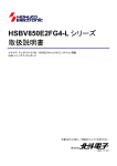
User Manual
32
Starter Kit for V850E2/FG4-L
User Manual: Hardware
RENESAS MCU
V850E2 F-Series
Y-ASK-V850E2-FG4L
All information contained in these materials, including products and product specifications,
represents information on the product at the time of publication and is subject to change by
Renesas Electronics Corp. without notice. Please review the latest information published by
Renesas Electronics Corp. through various means, including the Renesas Electronics Corp.
website (http://www.renesas.com).
www.renesas.com
March 2012
Starter Kit for V850E2/FG4-L User Manual
Notice
1.
All information included in this document is current as of the date this document is issued. Such information, however, is subject to change without
any prior notice. Before purchasing or using any Renesas Electronics products listed herein, please confirm the latest product information with a
Renesas Electronics sales office. Also, please pay regular and careful attention to additional and different information to be disclosed by Renesas
Electronics such as that disclosed through our website.
2.
Renesas Electronics does not assume any liability for infringement of patents, copyrights, or other intellectual property rights of third parties by or
arising from the use of Renesas Electronics products or technical information described in this document. No license, express, implied or otherwise, is
granted hereby under any patents, copyrights or other intellectual property rights of Renesas Electronics or others.
3.
You should not alter, modify, copy, or otherwise misappropriate any Renesas Electronics product, whether in whole or in part.
4.
Descriptions of circuits, software and other related information in this document are provided only to illustrate the operation of semiconductor products
and application examples. You are fully responsible for the incorporation of these circuits, software, and information in the design of your equipment.
Renesas Electronics assumes no responsibility for any losses incurred by you or third parties arising from the use of these circuits, software, or
information.
5.
When exporting the products or technology described in this document, you should comply with the applicable export control laws and regulations and
follow the procedures required by such laws and regulations. You should not use Renesas Electronics products or the technology described in this
document for any purpose relating to military applications or use by the military, including but not limited to the development of weapons of mass
destruction. Renesas Electronics products and technology may not be used for or incorporated into any products or systems whose manufacture, use,
or sale is prohibited under any applicable domestic or foreign laws or regulations.
6.
Renesas Electronics has used reasonable care in preparing the information included in this document, but Renesas Electronics does not warrant that
such information is error free. Renesas Electronics assumes no liability whatsoever for any damages incurred by you resulting from errors in or
omissions from the information included herein.
7.
Renesas Electronics products are classified according to the following three quality grades: “Standard”, “High Quality”, and “Specific”. The
recommended applications for each Renesas Electronics product depends on the product’s quality grade, as indicated below. You must check the
quality grade of each Renesas Electronics product before using it in a particular application. You may not use any Renesas Electronics product for
any application categorized as “Specific” without the prior written consent of Renesas Electronics. Further, you may not use any Renesas Electronics
product for any application for which it is not intended without the prior written consent of Renesas Electronics. Renesas Electronics shall not be in
any way liable for any damages or losses incurred by you or third parties arising from the use of any Renesas Electronics product for an application
categorized as “Specific” or for which the product is not intended where you have failed to obtain the prior written consent of Renesas Electronics. The
quality grade of each Renesas Electronics product is “Standard” unless otherwise expressly specified in a Renesas Electronics data sheets or data
books, etc.
“Standard”:
Computers; office equipment; communications equipment; test and measurement equipment; audio and visual equipment; home
electronic appliances; machine tools; personal electronic equipment; and industrial robots.
“High Quality”: Transportation equipment (automobiles, trains, ships, etc.); traffic control systems; anti-disaster systems; anti- crime systems; safety
equipment; and medical equipment not specifically designed for life support.
“Specific”:
Aircraft; aerospace equipment; submersible repeaters; nuclear reactor control systems; medical equipment or systems for life
support (e.g. artificial life support devices or systems), surgical implantations, or healthcare intervention (e.g. excision, etc.), and
any other applications or purposes that pose a direct threat to human life.
8.
You should use the Renesas Electronics products described in this document within the range specified by Renesas Electronics, especially with
respect to the maximum rating, operating supply voltage range, movement power voltage range, heat radiation characteristics, installation and other
product characteristics. Renesas Electronics shall have no liability for malfunctions or damages arising out of the use of Renesas Electronics products
beyond such specified ranges.
9.
Although Renesas Electronics endeavors to improve the quality and reliability of its products, semiconductor products have specific characteristics
such as the occurrence of failure at a certain rate and malfunctions under certain use conditions. Further, Renesas Electronics products are not
subject to radiation resistance design. Please be sure to implement safety measures to guard them against the possibility of physical injury, and injury
or damage caused by fire in the event of the failure of a Renesas Electronics product, such as safety design for hardware and software including but
not limited to redundancy, fire control and malfunction prevention, appropriate treatment for aging degradation or any other appropriate measures.
Because the evaluation of microcomputer software alone is very difficult, please evaluate the safety of the final products or system manufactured by
you.
10.
Please contact a Renesas Electronics sales office for details as to environmental matters such as the environmental compatibility of each Renesas
Electronics product. Please use Renesas Electronics products in compliance with all applicable laws and regulations that regulate the inclusion or use
of controlled substances, including without limitation, the EU RoHS Directive. Renesas Electronics assumes no liability for damages or losses
occurring as a result of your noncompliance with applicable laws and regulations.
11.
This document may not be reproduced or duplicated, in any form, in whole or in part, without prior written consent of Renesas Electronics.
12.
Please contact a Renesas Electronics sales office if you have any questions regarding the information contained in this document or Renesas
Electronics products, or if you have any other inquiries.
(Note 1) “Renesas Electronics” as used in this document means Renesas Electronics Corporation and also includes its majority- owned subsidiaries.
(Note 2) “Renesas Electronics product(s)” means any product developed or manufactured by or for Renesas Electronics.
R20UT0939ED0100
Mar 8, 2012
Page 2
Starter Kit for V850E2/FG4-L User Manual
Table of Contents
1.
Introduction ...............................................................................................................................4
2.
Quick Start – Connector and jumper overview ......................................................................5
2.1
2.2
2.3
2.4
2.5
3.
Software...................................................................................................................................16
3.1
3.2
4.
Microcontroller Area ................................................................................................................... 9
Pin Interfaces............................................................................................................................... 9
Power Supply Area...................................................................................................................... 9
2.3.1 Voltage Rail ............................................................................................................................... 10
Functional Areas ....................................................................................................................... 10
2.4.1 LEDs ........................................................................................................................................... 11
2.4.2 Pushbutton Switches................................................................................................................ 12
2.4.3 Analog Input - Potentiometer .................................................................................................. 12
2.4.4 Serial Communications Interfaces ......................................................................................... 13
On-chip Debug and Flash Programming Connector ............................................................. 16
Do not look into the LED beam!............................................................................................... 17
Power supply limitation of E1 Debugger ................................................................................ 17
Schematics ..............................................................................................................................18
R20UT0939ED0100
Mar 8, 2012
Page 3
Starter Kit for V850E2/FG4-L User Manual
1. Introduction
The Starter Kit for V850E2/FG4-L serves as a simple and easy to use platform for evaluating the
features and performance of Renesas Electronics’ 32-bit V850E2/FG4-L™ microcontrollers.
Features:
•
Connections for on-chip debugging and flash memory programming
•
Access to all microcontroller I/O pins
•
User interaction through potentiometer, buttons, and LEDs
•
Serial interface connections for RS232, LIN and CAN
•
Power supply by E1 On-Chip debugger or externally (3,3V to 5V DC input)
This document will describe the functionality provided by the Starter Kit and guide the user
through its operation. For details regarding the operation of the microcontroller, refer to the
V850E2/FG4-L User Manual which is available at www.renesas.eu
CAUTIONS
1. Do not look into the LED beam!
Special care must be taken with the high power LED D1 and RGB LED D6!
2. When power supply of E1 On-Chip debugger is used please note that the maximum
current provided by the debugger is limited to 200mA. Thus external power supply
is required in case all functions on the Starter Kit are used to full extend. In case
High power LED D1 is used while electrically supplied by E1 On-Chip debugger,
configure CN14 to “1-2 position” only.
R20UT0939ED0100
Mar 8, 2012
Page 4
Starter Kit for V850E2/FG4-L User Manual
2. Quick Start – Connector and jumper overview
CN1
Pin
Function
Pin
Pin
Function
Pin
1
GND
JP0_0
2
1
GND
P1_1
2
3
GND
JP0_1
4
3
GND
P1_2
4
5
GND
JP0_2
6
5
GND
P1_3
6
7
GND
JP0_3
8
7
GND
P1_4
8
9
GND
JP0_4
10
9
GND
P1_5
10
11
GND
JP0_5
12
11
GND
P1_6
12
13
GND
P0_0
14
13
GND
P1_7
14
15
GND
P0_1
16
15
GND
P1_8
16
17
GND
P0_2
18
17
GND
P1_9
18
19
GND
P0_3
20
19
GND
P1_10
20
21
GND
P0_4
22
21
GND
P1_11
22
23
GND
P0_5
24
23
GND
P1_12
24
25
GND
P0_6
26
25
GND
P1_13
26
27
GND
P0_7
28
27
GND
P1_14
28
29
GND
P0_8
30
29
GND
P1_15
30
31
GND
P0_9
32
31
GND
P11_0
32
33
GND
P0_10
34
33
GND
P11_1
34
35
GND
P0_11
36
35
GND
P11_2
36
37
GND
P0_12
38
37
GND
P11_3
38
39
VDD
VDD
40
39
VDD
VDD
40
Table 1.
R20UT0939ED0100
Mar 8, 2012
CN2
CN1 – CN2 – Signal assignment
Page 5
Starter Kit for V850E2/FG4-L User Manual
CN3
Pin
Function
Pin
Pin
Function
Pin
1
GND
P11_8
2
1
GND
P4_1
2
3
GND
P11_9
4
3
GND
P4_2
4
5
GND
P10_0
6
5
GND
P4_3
6
7
GND
P10_1
8
7
GND
P4_4
8
9
GND
P10_2
10
9
GND
P4_5
10
11
GND
P10_3
12
11
GND
P4_6
12
13
GND
P10_4
14
13
GND
P4_7
14
15
GND
P10_5
16
15
GND
P4_8
16
17
GND
P10_6
18
17
GND
P4_9
18
19
GND
P10_7
20
19
GND
P4_10
20
21
GND
P10_8
22
21
GND
P3_2
22
23
GND
P10_9
24
23
GND
P3_3
24
25
GND
P10_10
26
25
GND
P3_4
26
27
GND
P10_11
28
27
GND
P3_5
28
29
GND
P10_12
30
29
GND
P3_6
30
31
GND
P10_13
32
31
GND
P3_7
32
33
GND
P10_14
34
33
GND
P0_13
34
35
GND
P10_15
36
35
GND
P0_14
36
37
GND
P4_0
38
37
GND
P0_15
38
39
VDD
VDD
40
39
VDD
VDD
40
Table 2.
R20UT0939ED0100
Mar 8, 2012
CN4
CN3 – CN4 – Signal assignment
Page 6
Starter Kit for V850E2/FG4-L User Manual
Jumper /
Connector
CN5
Description
Setting
Note
Micro Controller power distribution
1–2
3–4
5–6
7–8
9 – 10
11 – 12
13 – 14
15 – 16
Common VDD rail (Note 2)
A0VDD to µC
REG1VDD to µC
E1VDD to µC
E0VDD to µC
REG0VDD to µC
OSCVDD to µC
I0VDD to µC
Supply by E1 Debugger
(Note 3)
+3.3V to +5.0V DC (optional)
(Note 3)
TX signal to DB9 CN12
RX signal to DB9 CN12
VBAT (12V externally) to CN12
LIN Signal to DB9 CN12
Ground to DB9 CN12
Sleep disabled
If bus termination is needed
CN6
Board supply selection
CN7
External supply (optional)
CN8
RS232
LIN
CN9
CN10
CN13
CAN0
CAN1
12V external supply (VBAT) for
LIN and CAN
CN14
Power selection LED D1
CN15
CN18
E1 Debugger interface
Test pin
Table 3.
3–4
1–2
3–4
7–8
9 – 10
11 – 12
1–2
1–2
3–4
1
2
1–2
3–4
1
2
12V DC from external
Ground from external
Low power setting
High power setting (CAUTION)
Connect E1 Debugger
VDD on board
Ground on board
Jumper / Connector settings overview
Notes:
1. Bold font indicates default setting.
2. Pins 1 – 2 can be used to measure µC total supply current.
3. In case CAN is used, the supply voltage must be 5.0V
R20UT0939ED0100
Mar 8, 2012
Page 7
Starter Kit for V850E2/FG4-L User Manual
Board Overview
Figure 1 provides a top level view of the Starter Kit. Highlighted in the image are several areas of
functionality.
Blue:
Microcontroller Area
Red:
Power Supply Area
Green: Functional Areas
These areas are described in detail in the following sections.
DC IN /
Power
UART /
LIN
CAN0
CAN1
DEBUG (E1)
Not used
Figure 1.
R20UT0939ED0100
Mar 8, 2012
Starter Kit top view
Poti /
Switches
Page 8
Starter Kit for V850E2/FG4-L User Manual
2.1 Microcontroller Area
The Microcontroller Area of the Starter Kit includes the following features:
•
Interfaces to all microcontroller I/O pins
•
Clock supply for microcontroller (16MHz)
2.2 Pin Interfaces
Each microcontroller I/O pin is connected to a Pin Interface. The Pin Interface is a group of pads
that allow easy probing of I/O pins, and provide the ability to selectively connect the I/O pins to
power, ground or other signals. Figure 2 shows a picture of unpopulated pin interfaces CN1 to CN
4. Through-hole pads with 0.1” spacing are provided for signal probing and connections. These
pads can be populated with standard 0.1” headers to facilitate signal probing.
Figure 2.
Pin Interfaces
2.3 Power Supply Area
The power supply area includes a DC jack type connector for providing external power supply to
the Starter Kit and its components. The external supply is reversibly protected against overload
and overvoltage. Nevertheless, please always observe the right polarity and voltage.
Caution: The voltage provided by connector CN7 is not regulated and is supplied to the
integrated circuits. Damage may occur if a voltage greater than that described in
Table 4 is supplied.
Connector
Description
Rail
CN7
DC Power Jack ID=2.0mm, center positive
VDD
Table 4.
R20UT0939ED0100
Mar 8, 2012
Input Voltage
Range
+3.3V to +5.0V
CN7 - Power Supply Connector Specification
Page 9
Starter Kit for V850E2/FG4-L User Manual
2.3.1 Voltage Rail
The Main Board provides two options for powering the board’s integrated circuits. Jumper CN6 is
provided to select from the available voltage sources (E1 On-Chip debugger or external supply),
or to completely disconnect the rail. A green indicator LED, D8, is provided to easily observe the
power state of the VDD voltage rail
Jumper
CN6
Description
Starter Kit supply voltage selection
Table 5.
Setting
1-2
3-4
Supply by
External (CN7)
E1 Debugger (CN15)
CN6 - Supply Voltage Selection
2.4 Functional Areas
The functional areas provide various circuits and components useful for interacting with the
microcontroller’s I/O:
UART / LIN
CAN
blue
LED
white
LED
Not used
RGB
Switches /
Poti
Figure 3.
R20UT0939ED0100
Mar 8, 2012
Functional Areas
Page 10
Starter Kit for V850E2/FG4-L User Manual
2.4.1 LEDs
2.4.1.1 White LED (High Brightness)
A RGB white high brightness / high power LED, D1, is provided to allow visual observation of
microcontroller output port state. The LED signal is active high.
LED
D1
Device Port
P0_15
Table 6.
White LED Signal
The maximum output power of D1 can be limited by jumper CN14:
Jumper
CN14
Setting
1-2
3-4
open
Table 7.
Description
Low output power
High output power
(CAUTION)
LED disabled
CN14 - White LED Power selection
2.4.1.2 Blue LEDs
Four blue LEDs, D2 to D5, are provided to allow visual observation of microcontroller output port
states. The LED signals are active high.
LED
D2
D3
D4
D5
Device Port
P1_3
P1_4
P1_5
P1_6
Table 8.
Blue LED Signals
2.4.1.3 RGB LED
An RGB (red / green / blue) LED, D6, is provided to allow visual observation of microcontroller
output port states. The LED signals are active high.
R20UT0939ED0100
Mar 8, 2012
LED
D6_Red
D6_Green
D6_Blue
Device Port
P1_14
P1_13
P1_12
Table 9.
RGB LED Signals
Page 11
Starter Kit for V850E2/FG4-L User Manual
2.4.2 Pushbutton Switches
Two pushbutton switches, SW1 and SW2, are provided to allow the switching of microcontroller
input port states. The switches are active low and normally open.
Switch
SW1
SW2
Device signal
RESET
P0_0 (INTP0)
Table 10.
Active Level
low
low
Inactive State
open
open
Pushbutton Switch Signals
2.4.3 Analog Input - Potentiometer
Potentiometer R25 is provided to generate analog voltages to the microcontroller’s analog input
ADAA0I0. By turning the potentiometer screw, a voltage between GND and VDD can be adjusted.
Potentiometer
R25
Table 11.
Analog Input FG4-L
ADAA0I0
Analog Input Signals
Note: R23 acts as overload protection in case P10_0 is configured to output accidentally.
R20UT0939ED0100
Mar 8, 2012
Page 12
Starter Kit for V850E2/FG4-L User Manual
2.4.4 Serial Communications Interfaces
2.4.4.1 RS232 and LIN
One RS232 transceiver, IC20, is supplied to provide a serial interface. The transceiver is
connected to the microcontroller’s UART interface (URTE10).
One Local Interconnect Network transceiver, IC21, is supplied to provide a LIN interface. The
transceiver is connected to the microcontroller’s LIN capable UART interface (URTE11).
The serial interfaces are connected to the DB9 connector CN12 via jumper CN8.
Caution: The DB9 connector CN12 is shared between the board’s RS232 and LIN interface.
Ensure that each interface is configured for the operation of only one, RS232 or
LIN, using jumper CN8.
Transceiver
UART instance
IC20
(RS232)
URTE10
IC21
(LIN)
URTE11
-
Table 12.
CN8 Setting
1–2
3–4
5–6
7–8
9 – 10
11- 12
13 - 16
Device signal
URTE10TX
URTE10RX
Ground
VBAT (12V DC)
URTE11
Ground
Not used
CN8 - Serial Communications Interfaces Signals
In order to operate the LIN interface, a 12V supply (VBAT) from external is required. This can be
achieved by connecting 12V DC to CN13 Pin1.
Connector
CN13
Table 13.
Position
1
2
Description
External 12V supply
Ground
CN13 – External 12V supply LIN
Caution: Ensure to NOT connect 12V DC to CN18 pin 1. This would create an overvoltage
condition for all electrical devices on the Starter Kit and will lead to irrecoverable
damage!
Connector
CN18
Table 14.
R20UT0939ED0100
Mar 8, 2012
Position
1
2
Description
VDD Test point
Ground
CN18 – Starter kit supply test points
Page 13
Starter Kit for V850E2/FG4-L User Manual
The operation modes of the LIN transceiver can be controlled by jumper CN9:
Jumper
CN9
Table 15.
Position
1–2
3-4
Description
Sleep disabled
Local wake-up input
(negative edge
triggered)
CN9 – LIN transceiver mode control
Please refer to the LIN transceiver’s data sheet for details.
2.4.4.2 CAN Interfaces
CAN transceivers, IC24 and IC25, are supplied to provide two CAN bus interfaces. Each
transceiver is connected to one of the microcontroller’s CAN interfaces (FCN0, FCN1). The CAN
bus interfaces are connected to the DB9 connectors CN17 and CN19 (not assembled on starter
kit). Jumper CN10 provides additional CAN bus interface configuration options including the
ability to selectively interconnect CAN bus interfaces on-board.
In order to achieve CAN bus communication, it is necessary to supply the transceivers with a
nominal 12 volt supply voltage in addition to the I/O voltage. This can be achieved by connecting
12V DC to CN13 Pin1.
Connector
CN13
Table 16.
Position
1
2
Description
External 12V supply
Ground
CN13 – External 12V supply CAN
Caution: Ensure to NOT connect 12V DC to CN18 pin 1. This would create an overvoltage
condition for all electrical devices on the Starter Kit and will lead to irrecoverable
damage!
Note: The Starter Kit’s supply voltage must be chosen with 5.0V to operate the CAN transceivers.
R20UT0939ED0100
Mar 8, 2012
Page 14
Starter Kit for V850E2/FG4-L User Manual
Transceiver
IC24
(CAN0)
IC25
(CAN1)
All
FCAN instance
FCN0
FCN1
All
Table 17.
R20UT0939ED0100
Mar 8, 2012
CN10
Setting
1–2
Enable termination resistor
3–4
Enable termination resistor
5–6
7–8
Connect to on-board CAN bus
Connect to on-board CAN bus
Device signal
CN10 - CAN Interfaces Signals
Page 15
Starter Kit for V850E2/FG4-L User Manual
2.5 On-chip Debug and Flash Programming Connector
Connectors CN15 is provided to allow the connection of microcontroller debug and flash
programming tools. Connector CN15 is a 14 pin, 0.1” pin pitch connector. The pinout of this
connector allows the connection of the Renesas E1 On-chip debugger.
3. Software
For a detailed description of the demonstration SW already programmed to the microcontroller,
please refer to the documentation that can be found in the related application folder on the CD
provided with the starter kit.
R20UT0939ED0100
Mar 8, 2012
Page 16
Starter Kit for V850E2/FG4-L User Manual
Precautions
3.1 Do not look into the LED beam!
Special care must be taken with the high power LED D1 and RGB LED D6!
3.2 Power supply limitation of E1 Debugger
When power supply of E1 On-Chip debugger is used please note that the maximum current
provided by the debugger is limited to 200mA. Thus external power supply is required in case all
functions on the Starter Kit are used to full extend. In case High power LED D1 is used while
electrically supplied by E1 On-Chip debugger, configure CN14 to “1-2 position” only.
R20UT0939ED0100
Mar 8, 2012
Page 17
Starter Kit for V850E2/FG4-L User Manual
4. Schematics
R20UT0939ED0100
Mar 8, 2012
Page 18
A
B
C
D
E
1B6<>
BI
ZBUS<100..1>
9
1
1
72
73
74
76
77
78
79
81
82
83
84
85
86
87
88
89
90
91
92
TP3
TP2
FIDUCIAL
2
4
6
8
10
12
14
16
18
20
22
24
26
28
30
32
34
36
38
40
2
4
6
8
10
12
14
16
18
20
22
24
26
28
30
32
34
36
38
40
2
4
6
8
10
12
14
16
18
20
22
24
26
28
30
32
34
36
38
40
2
4
6
8
10
12
14
16
18
20
22
24
26
28
30
32
34
36
38
40
52
51
61
62
63
64
65
66
47
48
49
50
55
56
57
58
59
60
71
2
4
6
8
10
12
14
16
18
20
22
24
26
28
30
32
34
36
38
40
2
4
6
8
10
12
14
16
18
20
22
24
26
28
30
32
34
36
38
40
42
41
40
39
37
36
35
34
33
32
31
30
29
28
27
46
45
44
43
N.A.
5.0V
VDD
CN4
1
3
5
7
9
11
13
15
17
19
21
23
25
27
29
31
33
35
37
39
2X20X2_54
5.0V
VDD
N.A.
CN3
1
3
5
7
9
11
13
15
17
19
21
23
25
27
29
31
33
35
37
39
2X20X2_54
5.0V
N.A.
VDD
CN2
1
3
5
7
9
11
13
15
17
19
21
23
25
27
29
31
33
35
37
39
2X20X2_54
5.0V
1
3
5
7
9
11
13
15
17
19
21
23
25
27
29
31
33
35
37
39
1
3
5
7
9
11
13
15
17
19
21
23
25
27
29
31
33
35
37
39
1
3
5
7
9
11
13
15
17
19
21
23
25
27
29
31
33
35
37
39
5.0V
VDD
5.0V
VDD
High Power white LED
1%
8
TR1
BC847B-7-F
B
1
2D8<>
R16
2.7K
EIA0603
1%
HIGH POWER LED
MX3AWT-A1-R250-000C51
D1
EIA0805
VDD
1%
R17
22
2
4
R45
390
SMD
4
23000137
EIA0603
1
3
CN14
1
3
2
4
TH
3
2
N.A.
2E4<>
BI
UART_LIN<1..4>
BI
3
4
1
2
5.0V
E0VDD
5.0V
E1VDD
2
7
EIA0603
1%
92
5.0V
100
97
98
94
95
VDD
R18
10K
1
3
5
7
9
11
13
15
17
19
21
23
25
27
29
31
33
35
37
39
76
77
78
79
80
81 81
82 82
83 83
84 84
85 85
86 86
87 87
88 88
89 89
90 90
91 91
92 92
93 93
94 94
95 95
96
97 97
98 98
99 99
100100
76
77
78
79
CAN0<1..2>
EIA0603
1%
IC1
C14
100N
50V
EIA0603
1
3
5
7
9
11
13
2
4
6
8
10
12
14
E1 INTERFACE
2
4
6
8
10
12
14
6
DEBUG (E1)
1
3
5
7
9
11
13
BI
C15
3.3U
10%
VDD_E1
3.3V
5.0V
5.0V
5.0V
REG1VDD
E1VDD
10V
E0VDD
REG0VDD 5.0V
EIA0805
ZBUS<100..1>
SAM_HTST-107-01-X-DV-A
CN15
1A9<>
P4_4_INTP2_URTE10RX_CSIG0SO
P4_5_CSIG0SC_KR0I3
P4_6_CSIG4SI_URTE11TX_KR0I2
P4_7_INTP4_URTE11RX_CSIG4SO_KR0I1
E1VDD[4]
P4_8_CSIG4SC_KR0I0
P4_9_CSIG0RY
P4_10_CSIG4RY
P3_2_TAUB0I2_TAUB0O2_KR0I7
P3_3_TAUB0I3_TAUB0O3_KR0I6
P3_4_TAUB0I4_TAUB0O4_KR0I5_CSIG0RY
P3_5_TAUB0I5_TAUB0O5_KR0I4_CSIG0SC
P3_6_TAUB0I6_TAUB0O6_CSIG0DCS_CSIG0SO
P3_7_TAUB0I7_TAUB0O7_CSIG0SI
P0_13_TAUJ0I1_TAUJ0O1_KR0I5_INTP7_CSIG0SI
P0_14_TAUJ0I2_TAUJ0O2_KR0I6_CSIG0DCS_CSIG0SO
P0_15_TAUJ0I3_TAUJ0O3_KR0I7_CSIG0SC
P0_12_TAUJ0I0_TAUJ0O0_KR0I0_INTP8__CSIG0SSI
P0_9_URTE10RX_KR0I4_INTP6_TAUB0O6_IICB0SCL
P0_8_URTE10TX_KR0I3_INTP5_TAUB0O5_IICB0SDA
E0VDD[3]
P0_7_URTE11RX_FCN1TX_KR0I2_INTP4
P0_6_FCN1RX_URTE11TX_KR0I1_NMI
P0_11_URTE11RX
P0_5_FCN0RX_INTP12
N.A.
EIA0603
1%
R24
1K
N.A.
16V
EIA0603
10%
FG4(-L)
5.0V
VDD
5
6
7
F
RESET
SW1
X1
16M
SESX1
5.0V
A0VDD
5
R27
0
N.A.
N.A.
R29
0
EIA0603
1%
EIA0603
1%
5.0V
VDD
5.0V
VDD
5.0V
INTP0
APEM\DTSM-63N
SW2
5.0V
OSCVDD
5.0V
E0VDD
IOVDD
4
37
36
35
34
33
32
31
30
29
28
27
50
49
48
47
46
45
44
43
42
41
40
39
5.0V
REG0VDD
5.0V
5.0V
5.0V
E0VDD
5.0V
5.0V
5.0V
5.0V
VDD
BI
3
2
4
6
8
10
12
14
16
2
4
6
8
10
12
14
16
3
CN5
1
3
CN6
1
3
TR5
BI
B
3.3V
5.0V
D4
EIA0603
R32
2.7K 1%
EIA0603
R31
2.7K 1%
EIA0603
R30
2.7K 1%
B
1
BC847B-7-F
TR7
B
1
5.0V
1
2
A0VDD
N.A.
1
2
CN13
1X2X2_54
B
TR3
SMAZ5V6
10V 5.6
+ C34
100U D10
FU1
5.0V
VDD +
VDD -
1X2X2_54
N.A.
2
TR4
B
CNTR2
CNTR1
SWITCH
OUTER
CN7
K.Hesse
DESIGNED
1.00
LUMBERG_1613_14
5.0V
VDD
4
3
2
1
1
D6
OSRAM
LATBT66B
RGB LED
POWER IN
3.3 TO 5.0V
CHECKED
FIRST RELEASE
PAGE 1 OF 2
1
EESS-0400-073-02
2011/10/25
Starter Kit For FG4(-L)
Renesas Electronics Europe GmbH
1
2
PWRIN
1
2
5.0V
VDD
TR2
B
5.0V
1
CN18
IOVDD REG1VDD
5.0V
12.0V
VBAT
Extern 12V input
VDD +
VDD -
D5
L-C192LBCT(BL)
BC847B-7-F
TR8
1
External
Supply
Array of blue LEDs
L-C192LBCT(BL)
RAYCHEM/MINISMDC050-2
5.0V
1
PWRFU
2
4
VDD_E1
2
4
B
TR6
D3
EIA0603
1%
L-C192LBCT(BL)
BC847B-7-F
2B6<>
1
5.0V
VDD
2
L-C192LBCT(BL)
D2
BC847B-7-F
SMD
4
23000137
FR<1..3>
VDD_CN
D8
1
3
5
7
9
11
13
15
5.0V
5.0V
1
E1VDD
R37
2.7K
EIA0603
1%
R36
2.7K
EIA0603
1%
R35
2.7K
EIA0603
1%
R34
2.7K
EIA0603
1%
LTST-C190KGKT(GN)
5.0V
E1VDD
1
3
5
7
9
11
13
15
2
3
1
VDD
POWER SELECT
2D4<>
SAM_TSM-108-XX-X-DV
OSCVDD
A0VDD
5.0V
E1VDD
CAN1<1..2>
REG1VDD
5.0V
1
2
E1VDD
5.0V
33
32
31
30
29
28
37
36
42
41
40
39
E0VDD
REG0VDD
50
49
48
47
46
45
44
43
42
41
40
39
38
37
36
35
34
33
32
31
30
29
28
27
26
OSCVDD
5.0V
IOVDD
P10_9_ADCA0TRG0_ADCA0I9
P10_8_ADCA0I8
P10_7_ADCA0I7
P10_6_ADCA0I6
P11_0_ADCA0I16
P11_1_ADCA0I17
P11_2_ADCA0I18
P11_3_ADCA0I19
P1_1_TAUB0I1_TAUB0O1_FCN1RX_FCN0TX
P1_2_TAUB0I2_TAUB0O2_CSIG7SI_FCN1TX
P1_3_TAUB0I3_TAUB0O3_CSIG7DCS_CSIG7SO
P1_4_TAUB0I4_TAUB0O4_CSIG7SC
E1VDD[2]
P1_5_TAUB0I5_TAUB0O5_CSIG7RY
P1_6_TAUB0I6_TAUB0O6__CSIG7SSI
P1_7_TAUB0I7_TAUB0O7_FCN0RX
P1_8_TAUB0I8_TAUB0O8
P1_9_TAUB0I9_TAUB0O9_INTP3
P1_10_TAUB0I10_TAUB0O10_INTP4
P1_11_TAUB0I11_TAUB0O11_INTP5
P1_12_TAUB0I12_TAUB0O12_INTP6
P1_13_TAUB0I13_TAUB0O13_INTP7
P1_14_TAUB0I14_TAUB0O14_INTP8
P1_15_TAUB0I15_TAUB0O15_INTP9
E1VDD[1]
Push Buttons
APEM\DTSM-63N
C18
15P
CN1
1
3
5
7
9
11
13
15
17
19
21
23
25
27
29
31
33
35
37
39
R19
10K
C16
4.7U
74
73
72
71
1
50V
EIA0603
10%
50V
EIA0603
1%
1
2
3
EIA0603
1%
R22
10K
C17
10N
11
12
13
50V
EIA0603
1%
2X20X2_54
R20
10K
C20
100N
18
19
2
4
6
8
10
12
14
16
18
20
22
24
26
28
30
32
34
36
38
40
R21
82K
EIA0603
1%
R23
1K
61
66
65
64
63
62
61
60
59
58
57
56
55
C19
15P
23
24
25
23
2
4
6
8
10
12
14
16
18
20
22
24
26
28
30
32
34
36
38
40
EIA0603
1%
10V
EIA0805
10%
EIA0603
1%
52
51
52
51
75
74
73
72
71
70
69
68
67
66
65
64
63
62
61
60
59
58
57
56
55
54
53
52
51
E1VSS
P4_3_CSIG0SI_URTE10TX
P4_2_TAUB0I15_TAUB0O15_URTE2TX
P4_1_TAUB0I14_TAUB0O14_URTE2RX
P4_0_TAUB0I13_TAUB0O13
E1VDD[3]
REG1VDD
REG1C
REG1VSS
P10_5_ADCA0I5
P10_4_ADCA0I4
P10_3_ADCA0I3
P10_2_ADCA0I2
P10_1_ADCA0I1
P10_0_ADCA0I0
P10_15_ADCA0I15
P10_14_ADCA0I14
P10_13_ADCA0I13
P10_12_ADCA0I12
P10_11_ADCA0TRG2_ADCA0I11
P10_10_ADCA0TRG1_ADCA0I10
A0VSS
A0VDD
P11_8
P11_9
P0_4_FCN0TX_INTP11
JP0_0_INTP0_TAUJ0I0_TAUJ0O0_FLCS0SI_FLUR0RX_FLUR0TX_DCUTDI
P0_10_URTE11TX_INTP9
E0VDD[1]
JP0_1_INTP1_TAUJ0I1_TAUJ0O1_FLCS0SO_FLUR0TX_DCUTDO
JP0_2_INTP2_TAUJ0I2_TAUJ0O2_FLCS0SCI_DCUTCK
JP0_3_INTP3_TAUJ0I3_TAUJ0O3_DCUTMS
REG0VDD
REG0C
REG0VSS
JP0_4__DCUTRST
JP0_5_NMI__DCURDY
RESET_Z
X2
X1
OSCVSS
OSCVDD
P0_0__CSIG4SSI_ADCA0TRG0_INTP0
P0_1_CSIG4DCS_CSIG4SO_URTE2RX_INTP1_TAUB0O1_FLMD1
E0VDD[2]
E0VSS
I0VDD
FLMD0
P0_2_CSIG4SI_ADCA0TRG2_URTE2TX_INTP2_TAUB0O2_MODE0
P0_3_CSIG4SC_ADCA0TRG1_INTP3_MODE1
50V
EIA0603
10%
2
5
6
7
11
12
18
19
24
25
1
100
98
97
95
94
3
99
93
50V
EIA0603
1
1
2
2
3
3
4
5
5
6
6
7
7
8
9
10
11 11
12 12
13 13
14
15
16
17
18 18
19 19
20
21
22
23
24
25
R26
EIA0603
10K 1%
EIA0603
1%
R28
10K
C21
10N
4
C22
50V
100N
EIA0603
Potentiometer
C23
100N
5
50V
EIA0603
R25
10K
C24
100N
50V
EIA0603
5.0V
C27
100N
50V
EIA0603
VDD
C25
50V
100N
EIA0603
R43
220
C29
100N
EIA0603
1%
6
C26
100N
50V
EIA0603
EIA0603
1%
C28
100N
50V
EIA0603
EIA0603
1%
50V
EIA0603
7
C30
100N
EIA0603
1%
C31
100N
8
50V
EIA0603
R42
390
3
R40
390
3
2
R44
390
3
EIA0603
1%
R41
390
50V
EIA0603
2
3
2
C32
100N
4
EIA0603
1%
BC847B-7-F
3
R38
120
3
1
EIA0603
1%
BC847B-7-F
2
R33
120
3
2
2
50V
EIA0603
R39
150
3
B
2
R
C33
100N
BC847B-7-F
R20UT0939ED0100
Mar 8, 2012
G
2
9
APPROVED
2011/11
A
B
C
D
E
F
Starter Kit for V850E2/FG4-L User Manual
Page 19
A
B
C
D
E
9
1C7<>
BI
12.0V
VBAT
UART_LIN<1..4>
3
4
1
2
1
3
R10
10K
EIA0603
1%
CN9
1
3
2
4
SMD
4
23000137
8
2
4
5.0V
VDD
C82
100N
100N
EIA0603
C85
470N
C84
C2PLUS
C2MINUS
T1IN_TTL
T2IN_TTL
R1OUT_TTL
R2OUT_TTL
5
6
12
11
13
10
17
16
1 RXD
2 NSLP
3 NWAKE
8 INH
TXD
LIN
BAT
GND
4
6
7
5
R1IN_RS232
R2IN_RS232
T1OUT_RS232
T2OUT_RS232
VMINUS
VPLUS
EN
12.0V
7
C6
470N
C83
470N
C88
100N
EIA0603
VBAT
14
9
15
8
7
3
1
IC20
MAX3222ECWN+
IC21 TJA1020T
LIN
C1PLUS
C1MINUS
SHDN
2
4
18
VCC
GND
EIA0603
16V
EIA0603
10%
EIA0603
C1
100N
N.A.
C2
100N
N.A.
16V
EIA0603
10%
5.0V
1n
EIA0603
C13
1K
EIA1206
R14
16V
EIA0603
10%
VDD
N.A.
1C2<>
BI
1
3
5
7
9
11
13
15
6
TP1
1
N.A.
RXD
ERRN
RXEN
7
13
12
3
WAKE
TXD
TXEN
BGE
STBN
EN
5
6
8
9
3
IC2
1
2
15
10
11
1
2
3
4
5
6
7
8
9
GND
GND
1
2
3
4
5
6
7
8
9
CN12
MALE
INH1
INH2
TJA1080ATS/2/T
BP
BM
12.0V
VBAT
2
1
18
17
5
2
1
L1
4
1
3
N.A.
N.A.
CN11
1
3
N.A.
2
4
SMD
4
23000137
0
R2
3
2
4
1D2<>
1B7<>
ACT45B-510-2P-TL
R1 N.A.
0
K202XHT-E9P-N
KYC_K202XHT_E9P
FLEXRAY (FG4 only)
TRXD0
TRXD1
2
4
6
8
10
12
14
16
11
10
2
4
6
8
10
12
14
16
SAM_TSM-108-XX-X-DV
CN8
5.0V
VDD
1
3
5
7
9
11
13
15
FR<1..3>
12.0V
VBAT
20
14
VBUF
VBAT
UART
4
19
VIO
VCC
GND
16
16V
EIA0603
10%
EIA0603
1%
C3
100N
5
C4
100N
R3
51
6
R12
0
C5
4.7N
BI
BI
CAN1<1..2>
CAN0<1..2>
4
2
1
4
1
2
10
11
1
2
3
4
5
6
7
8
9
R5
0
EIA0603
1%
N.A.
GND
GND
1
2
3
4
5
6
7
8
9
CN16
K202XHT-E9S-N
KYC_K202XHT_E9S
FEMALE
EIA0603
1%
R4
0
5.0V
VDD
5.0V
VDD
1
2
3
4
5
6
7
1
2
3
4
5
6
7
3
ERR_Z
STB_Z
CANH
CANL
SPLIT
VBAT
WAKE
TJA1041T
TX0
GND
VCC
RX0
VIO
EN
INH
IC25
3
Driver
ERR_Z
STB_Z
CANH
CANL
SPLIT
VBAT
WAKE
TJA1041T
CAN1
TX0
GND
VCC
RX0
VIO
EN
INH
Driver
CAN0
IC24
EIA0603
16V 10%
7
R13
51
EIA0603
1%
N.A.
N.A.
50V
EIA0603
10%
EIA0603
1%
N.A.
N.A.
100N
C7
100N
C9
C10
100N
8
N.A.
EIA0603
16V 10%
16V
EIA0603
10%
16V
C8
EIA0603
100N
10%
14
13
12
11
10
9
8
14
13
12
11
10
9
8
EIA0603
1%
EIA0603
1%
1%
R8
1K
R9
1K
EIA0603
1%
16V
EIA0603
10%
16V
EIA0603
10%
R6
0
R7
0
C11
100N
C12
100N
5.0V
VDD
R15
120
12.0V
VBAT
VBAT
12.0V
5.0V
VDD
EIA0805
1%
EIA0805
1%
R20UT0939ED0100
Mar 8, 2012
R11
120
F
9
CN10
1
2
3
4
5
6
7
8
CAN0H
CAN0L
2
2
4
6
8
SAM_TSM-104-XX-X-DV
CAN1H
CAN1L
1
3
5
7
2
K.Hesse
DESIGNED
1.00
N.A.
GND
GND
1
2
3
4
5
6
7
8
9
CN19
CHECKED
FIRST RELEASE
SDT09166G3TR4BA
SUBD9_F
N.A.
GND
GND
1
2
3
4
5
6
7
8
9
SDT09166G3TR4BA
SUBD9_F
CN17
PAGE 2 OF 2
1
EESS-0400-073-02
2011/10/25
Starter Kit For FG4(-L)
Renesas Electronics Europe GmbH
10
11
1
2
3
4
5
6
7
8
9
10
11
1
2
3
4
5
6
7
8
9
1
APPROVED
2011/11
A
B
C
D
E
F
Starter Kit for V850E2/FG4-L User Manual
Page 20
REVISION HISTORY
Rev.
Starter Kit for V850E2/FG4-L User Manual: Hardware
Date
Description
Page
1.00
March, 2012
⎯
Summary
First Edition issued
V850E2/FG4-L Starter Kit User Manual: Hardware
Publication Date:
Rev.1.00
March, 2012
Published by:
Renesas Electronics Europe
http://www.renesas.com
SALES OFFICES
Refer to "http://www.renesas.com/" for the latest and detailed information.
Renesas Electronics America Inc.
2880 Scott Boulevard Santa Clara, CA 95050-2554, U.S.A.
Tel: +1-408-588-6000, Fax: +1-408-588-6130
Renesas Electronics Canada Limited
1101 Nicholson Road, Newmarket, Ontario L3Y 9C3, Canada
Tel: +1-905-898-5441, Fax: +1-905-898-3220
Renesas Electronics Europe Limited
Dukes Meadow, Millboard Road, Bourne End, Buckinghamshire, SL8 5FH, U.K
Tel: +44-1628-585-100, Fax: +44-1628-585-900
Renesas Electronics Europe GmbH
Arcadiastrasse 10, 40472 Düsseldorf, Germany
Tel: +49-211-65030, Fax: +49-211-6503-1327
Renesas Electronics (China) Co., Ltd.
7th Floor, Quantum Plaza, No.27 ZhiChunLu Haidian District, Beijing 100083, P.R.China
Tel: +86-10-8235-1155, Fax: +86-10-8235-7679
Renesas Electronics (Shanghai) Co., Ltd.
Unit 204, 205, AZIA Center, No.1233 Lujiazui Ring Rd., Pudong District, Shanghai 200120, China
Tel: +86-21-5877-1818, Fax: +86-21-6887-7858 / -7898
Renesas Electronics Hong Kong Limited
Unit 1601-1613, 16/F., Tower 2, Grand Century Place, 193 Prince Edward Road West, Mongkok, Kowloon, Hong Kong
Tel: +852-2886-9318, Fax: +852 2886-9022/9044
Renesas Electronics Taiwan Co., Ltd.
7F, No. 363 Fu Shing North Road Taipei, Taiwan
Tel: +886-2-8175-9600, Fax: +886 2-8175-9670
Renesas Electronics Singapore Pte. Ltd.
1 harbourFront Avenue, #06-10, keppel Bay Tower, Singapore 098632
Tel: +65-6213-0200, Fax: +65-6278-8001
Renesas Electronics Malaysia Sdn.Bhd.
Unit 906, Block B, Menara Amcorp, Amcorp Trade Centre, No. 18, Jln Persiaran Barat, 46050 Petaling Jaya, Selangor Darul Ehsan, Malaysia
Tel: +60-3-7955-9390, Fax: +60-3-7955-9510
Renesas Electronics Korea Co., Ltd.
11F., Samik Lavied' or Bldg., 720-2 Yeoksam-Dong, Kangnam-Ku, Seoul 135-080, Korea
Tel: +82-2-558-3737, Fax: +82-2-558-5141
© 2012 Renesas Electronics Corporation. All rights reserved.
Colophon 1.0
V850E2/Fx4 Starter Kit
R20UT0939ED0100