1
RENA Direct Address Printer
DA615
Instruction Manual
This manual is written and verified thoroughly. Yet, we will not undertake liability for any fault.
Technical specifications may change due to design advances.
The data stated are nominal values only.
Order No. R0615.0.980 State 12.99
CONTENTS
Page
Important notes on safety
1.
Introduction
1.1
What can the DA615 address printer do ?
1.1
Presenting the DA615 address printer
1.2
Control panel
1.3
In off-line mode
In programming mode
1.3
1.3
Brief guide
2.
1.4
Operation
2.1
Connecting the printer
Interface cable
Power cable
2.1
2.1
Switching the printer on
3.
2.2
What does the display show ?
What do the keys mean ?
When are the keys active ?
OFF-LINE MODE
ON-LINE MODE
2.2
2.3
2.4
2.4
2.4
Addressing media
3.1
Adjusting the support height
3.1
Adjusting the print-head spacing
3.1
Transport direction
3.2
Lateral guides
3.4
Paper transport without address printing
3.4
Positioning the media
3.5
Positioning print areas
3.5
Pinwheels
3.7
Paper guide
3.7
Adjusting the print position
3.8
Address block rotation
Left margin
Clearance
Print test
\text\etd\DA615\contents
2.1
I.1
3.8
3.8
3.8
3.9
DA615 instruction manual
Contents
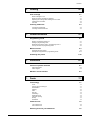
4.
Printing
4.1
Print cartridge
4.1
Which cartridges to use
When should the cartridge be replaced ?
Replacing the cartridge and resetting the ink counter
Cleaning the ink nozzles
Print test
Counting addresses
Counting test addresses
Counting received addresses
5.
Printer functions
Programming mode
What is programming mode for ?
Getting to programming mode
What does the display show in programming mode ?
The key functions in programming mode
Menu overview
5.1
5.1
5.1
5.1
5.2
5.2
5.4
5.14
5.14
Interfaces
6.1
Signal description
Pulse diagram
6.1
6.2
6.3
RS-232-C serial interface
Fonts
6.4
7.1
Terminology
7.1
Fonts
Serif or sans serif font type
Normal/italics
Spacing
Pitch
Dot size
Underlining
Expanded mode
Character spacing
Quality
Orientation
Character sets
7.1
7.1
7.1
7.2
7.2
7.3
7.3
7.3
7.3
7.4
7.4
7.5
7-bit character set
8-bit character set
7.5
7.5
Selecting fonts for your addresses
\text\etd\DA615\contents
4.3
4.3
Initializing the printer
Centronics parallel interface
7.
4.3
5.3
Explaining the menu fields
Example of an application in programming mode
6.
4.1
4.1
4.2
4.3
4.3
I.2
7.6
DA615 instruction manual
Contents
8.
9.
Error messages and hints
8.1
General error messages
8.1
Error messages for soft fonts
8.3
Notes on maintenance
8.3
Annex
9.1
A. Technical data
A.1
B. Character sets
B.1
7-bit character sets
8-bit character sets
B.1
B.4
C. Glossary
C.1
D. Index
D.1
E. Accessories
E.1
Guide brackets
Pinwheels
Paper guide
Variant list
E.1
E.2
E.2
Declaration of conformity
\text\etd\DA615\contents
I.3
DA615 instruction manual
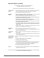
Important Notes on Safety
PLEASE READ THESE INSTRUCTIONS CAREFULLY.
Keep them within easy reach for later use.
All direction and warning labels on instruments must be observed.
Setting up the
printer
Electrical
safety
•
•
•
•
•
•
•
•
•
Operational
safety
Cleaning the
printer
Let your service
partner check
the printer !
•
•
•
•
The printer must be protected from moisture
When connecting the printer to the power supply, observe the rated
values for the power connection on the type plate.
Check the voltage setting at the printer’s power input module.
For reasons of electrical safety, the power connection socket must be
equipped with a grounded conductor contact.
The printer has a double-pole fuse protection! In the event of fuse
failure, electrical parts in the instrument may still be live.
Run the power supply cable so that no-one can trip over it. Also ensure
that nothing is placed upon the cable.
If the printer remains unused over a longer period of time, disconnect it
from the power supply. This ensures that no damage will be caused by
voltage surges.
Never open the printer. For reasons of electrical safety, it may be
opened only by authorized service personnel.
Never touch the internal parts of the printer while it is running !
To avoid damaging the printer, use only spares that have been
approved by the manufacturer.
Before cleaning, the printer must always be disconnected from the
power supply.
Use no liquid or aerosol cleaning agents. Cleaning is best done with a
cloth dampened with water.
IN THE FOLLOWING CASES, DISCONNECT THE PRINTER FROM THE POWER
SUPPLY !
•
•
•
•
•
•
Spares
When setting up the printer, ensure that it is positioned securely and is
level. If it is allowed to tilt, roll away or drop, injuries may result.
•
The power cable or power socket are damaged.
Liquid has penetrated the printer.
The printer was exposed to moisture.
If the printer does not function as described in the operating instructions,
or you can obtain no improvements with the aid of these instructions.
The printer was dropped and/or the housing is damaged.
If the printer shows clear signs of a defect.
In the event of repair, only original spares or those corresponding to the
original parts should be used.
Consult your service partner about all queries relating to service and repair. This will ensure that
your printer will operate perfectly at all times.
\text\etd\allege\ impnotes
Important Notes on Safety
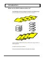
1. Introduction
What can the DA615 address printer do?
The DA615 address printer is an ink-jet printer ensuring a high-quality printout. It
prints addresses at the correct positions on media such as envelopes, cards,
brochures, magazines and other documents up to 10 mm in thickness.
A total of thirteen installed fonts lets you choose from a large selection of
different typefaces.
The width of the print area is 600 mm.
Printing is performed with standard exchangeable ink cartridges.
\text\etd\da615\Introduction
1.1
DA615 instruction manual
Introduction
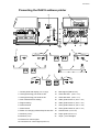
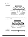
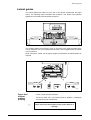
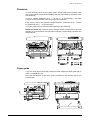
Presenting the DA615 address printer
1. Control panel with display (see next page)
12.
Mid-support (R0615.0.098)
2. Locking/unlocking print units H4-H3
13.
Guide bracket 1 (R0615.1.076)
3. Locking/unlocking print units H2-H1
14.
Guide bracket 2 (R0615.1.077)
4. Print media thickness setting
15.
Wide guide bracket 3 (R0615.1.078)
5. Support setting
16.
Wide guide bracket 4 (R0615.1.079)
6. Power terminal
17.
Short guide bracket 5 (R0615.1.080)
7. Power switch
18.
Short guide bracket 6 (R0615.1.081)
8. Switch for changing media transport direction 19.
Knurled knob (K2913.029)
9. Interface (parallel)
20.
Paper guide (R0615.2.051)
21.
Inkjet – print cartridges
10. Interface (serial)
11a. Socket for control signal
11b. Connector for control signal (E0906.024)
\text\etd\da615\Introduction
1.2
DA615 instruction manual
Introduction
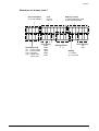
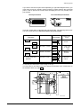
Control panel
In off-line mode
On-line mode
Off-line mode
Measurement
of paper width
Start/stop
Paper transport
Repeat print-out of
last address(es)
Print-out of a test address
Programming mode
Measuring the transport speed
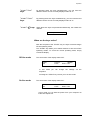
In programming
mode
In programming mode, menu settings are made on the printer. In this
mode, the upper line of key descriptors applies (END, NEXT, PREV,
ENTER)
End of programming-mode
Select next value
in combination
with the power
switch
\text\etd\da615\Introduction
Address rotation by 180°
Change activation between
Menu field and option field
Select previous value
Key combination
Meaning
Power on + Prog
Power on + Start
Reset to works default
HexDump
1.3
DA615 instruction manual
Introduction
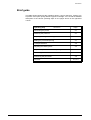
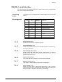
Brief guide
The table shown below lists the operating steps in correct sequence. It allows you
to perform a test print quickly without any prior knowledge. You can find the detailed
description of the various operating steps on the pages shown in the right-hand
column.
Operating step
Page
Connecting the printer
2.1
Switching the printer on
2.1
Adjusting the height of the supports
3.1
Setting the print-head spacing
3.1
Transport direction
3.2
Adjusting the lateral guides
3.4
Paper transport without address printing
3.4
Positioning the media
3.5
Positioning the print areas
3.5
Print test
\text\etd\da615\Introduction
described on
3.9; 4.3
1.4
DA615 instruction manual
1.
Introduction
1.1
What can the DA615 address printer do?
1.1
Presenting the DA615 address printer
1.2
Control panel
1.3
In off-line mode
In programming mode
in combination with the power switch
Brief guide
\text\etd\da615\Introduction
1.3
1.3
1.3
1.4
1.0
DA615 instruction manual
2. Operation
Connecting the printer
Interface cable
Plug the interface cable into terminal (9) on the right-hand side of
the printer for a parallel interface connection or into terminal (10)
for a serial interface connection. Then lock it and connect the cable
to your PC.
Connection to
media feed unit
Connect the cable of the media feed unit to the connector supplied
(11b). Connect the cable to the control signal terminal (11a).
Power cable
CAUTION!
The DA615 is an instrument of
Protection Class 1
The printer may be operated only from grounded power outlets !
Plug the power cable into the right-hand side of the printer (6).
Switching the printer on
Switch the printer on via the power switch (7).
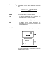
The display in the control
panel (10) shows the
following brief message for initialization
When the printer is in online mode, the display
shown
on
the
right
appears (for example).
DA615
Inkjet
Initialization
100%
On
Cour12
000000
FAST
Set1U Nor
The messages are explained on the next page.
\text\etd\DA615/operation
2.1
DA615 instruction manual
Operation
What does the display show ?
Ink consumption
% ink still available
Font
Cour12
Helv12
Print quality
600D
Operating mode
450D
On = on-line mode
300D
Off = off-line mode
300F
Test = test-print
200D
Pap = paper feed/
150D
paper eject
\text\etd\DA615/operation
2.2
Address counter
In normal operating mode
In test operating mode
Setting number
0-9
Print direction
Nor
Rev
Setting
L = locked
U = unlocked
DA615 instruction manual
Operation
What do the keys mean ?
On-line mode
Off-line mode
Measurement
of paper width
Start/stop
Paper transport
Print-out of a test address
Measuring the transport speed
☞
Repeat print-out of
last address(es)
Programming mode
Address rotation by 180°
The four middle keys have a dual meaning, depending on the operating mode!
"START" key
The "Start" key is used to switch between on-line and off-line
modes.
"PAP" key
The "Pap" key is used to start or stop the transport unit.
"TEST" key
The "Test" key is used to print the test address onto all sheets of
paper which are fed in.
If you press the “Test” key a second time, the print test is
terminated.
"PROG" key
The "Prog" key gets you into programming mode.
key
key
\text\etd\DA615/operation
This key allows you to repeat the print out of the last (up to 20)
addresses.
This key allows you to measure the width of an inserted sheet of
paper.
2.3
DA615 instruction manual
Operation
"START"+"PAP"
keys
By pressing these two keys simultaneously, you can reset the
address counter from its currently displayed value to "0".
"START"+"TEST"
keys
By pressing these two keys simultaneously, you can reset the test
address counter from its currently displayed value to "0".
"START"+
keys When these two keys are pressed simultaneously, the nozzles are
cleaned.
NOTE ! Higher ink consumption !!
When are the keys active?
With the exception of the "START" key, the keys are active only in
off-line operating mode.
The "START" key allows you to switch between on-line and off-line
operating modes. To check the current operating mode, simply
consult the display.
Off-line mode
The second line of the display reads "Off".
100%
Off
Cour12
FAST
000000
Set1U Nor
In this mode you can change
keyboard.
the
settings
via
the
Pressing the "START" key returns you to on-line mode.
On-line mode
The second line of the display reads "On".
100%
On
Cour12
FAST
000000
Set1U Nor
In this mode you can start the printer from your computer via
instruction sequences.
\text\etd\DA615/operation
2.4
DA615 instruction manual
2.
Operation
2.1
Connecting the printer
Interface cable
Connection to media feed unit
Power cable
Switching the printer on
What does the display show ?
What do the keys mean ?
When are the keys active?
OFF-LINE MODE
ON-LINE MODE
\text\etd\DA615/operation
2.0
2.1
2.1
2.1
2.1
2.1
2.2
2.3
2.4
2.4
2.4
DA615 instruction manual
Addressing media
3. Addressing media
Adjusting the support height
The DA615 operates with single-sheet feed and uses a band for transporting the
media.
The DA615 support can be raised or lowered by up to 43 mm in order to adjust its
level to adjacent equipment. To do this, turn the rotary knob (5) in the direction of
the arrow (see diagram below).
The set distance can be read off from the right-hand scale (arrow).
\text\etd\DA615/address
3.1
DA615 instruction manual
Addressing media
Setting the print-head spacing
When printing media up to 1 mm in thickness, you can work with the smallest
spacing between print-head and contact plate. Turn the rotary button (4) in the
direction of the arrow as far as the left stop (see left diagram on the next page).
If the print is smudged or if you are using thick media such as magazines, the
spacing must be increased.
Turn the rotary knob (4) clockwise until the medium (up to 10 mm) fits into the gap
(d).
Place two thin (< 1 mm thick) or one thick (> 1 mm thick) media between all four
pairs of contact bars and the roller (gap D). Turn the rotary knob to the left again
until the medium can be pulled out against a slight resistance.
The set spacing can be read off the left-hand scale (arrow).
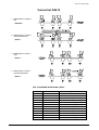
Transport direction
The transport direction from right to left is set at the works as the default option.
The mounts of the print cartridges are numbered through from right to left as H1 to
H4 following the sequence in which the medium (D) reaches the four print
cartridges (see following diagram). When the media is fed in the opposite transport
direction, it first reaches print-head H4 (see broken line in the diagram below).
If you need to use the opposite transport direction, you must first replace the holddown sets. To do this, refer to the following page and to the first and third sections
of the variant list.
\text\etd\DA615/address
3.2
DA615 instruction manual
Addressing media
Hold-down set 4 – 1 must be replaced completely by set 7 – 10 (Accessories!). The
order numbers for the hold-down units are given in the variant list.
Switch the printer off ! Remove the two hexagon-socket screws (see arrow in left
diagram) of each hold-down unit and replace them by the corresponding variants
(see table).
Ensure correct assignment of
the hold-down units to the
print-head mounts!
Media feed direction def
Print-head
mount
H1
H2
H3
H4
Media feed direction
Def.
Opp.
1
2
3
4
10
9
8
7
Media feed direction opp
Check these points before switching the printer on !
•
Check to ensure that the hold-down units of print-head mounts H4/H3 and
H2/H1 are all aligned in the feed direction.
•
When changing feed directions, activate switch (8) – after replacing the holddown units. The white arrow now applies. Compare the switch position with the
right-hand diagram.
Media feed direction
8
☞
Def.
Opp.
The switch position is only effective after the printer has been switched on !
Any changes made via the menu or via control sequences are effective only
as long as the printer is switched on!
The direction can also be changed in programming mode or via control sequences.
Read the interface description relating to this point.
\text\etd\DA615/address
3.3
DA615 instruction manual
Addressing media
Lateral guides
Two lateral guides are fitted on each side of the printer (media-feed and eject
sides). The following figure illustrates their positions. The broken lines indicate
appliances connected before and after the printer.
The chapter entitled “Accessories” gives an overview of the guide brackets which
can be ordered to suit your individual format sizes if those supplied with the printer
are not sufficient.
When using thick media, set the paper support (12) between the lateral guides as
required.
Paper feed
without
address
printing
–
Press the "PAP" key: The inserted sheet is pulled in, transported
through the printer and ejected.
☞
\text\etd\DA615/address
Place a sheet onto the feed side
Never touch the internal parts of the printer while it is
running !
3.4
DA615 instruction manual
Addressing media
Positioning the media
Each feed side is equipped with two paper light barriers (P-Li) for measuring the
print position (see diagram below).
The medium must always completely cover one of the two
paper light barriers in its transport path!
Positioning print areas
Each of the two print-head pairs H1-H2 and H3-H4 has its own print area (DB1-2
and DB3-4) and can be separately adjusted with respect to the other one. Both
print-head pairs have an adjustment scale (Sk in the diagram below).
To obtain a 12-line print-out with equal line spacing (cf. left diagram on the next
page), you must shift the print-head pairs with respect to each other by an offset (V)
of 25.4 mm / 1 inch as shown in the diagram below.
\text\etd\DA615/address
3.5
DA615 instruction manual
Addressing media
If you want to use the two print areas separately (cf. right-hand diagram below), you
must make sure that a specific minimum offset (V) exists between the print-head
pairs in order to prevent the contact rollers smudging the ink or any overlap of the
print formats.
12-line print format
Two individual print formats
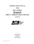
There are several ways of adjusting the print-head pairs. The following table shows
how each offset affects the distance between the print formats.
Arrangement of printhead pairs
H4-H3
Minimum offset V
Position of
print formats
38 mm / 1½ inch
DB3-4
a
H2-H1
H2-H1
25.4 mm / 1 inch
0 mm / inch
(= 12 line
print)
DB1-2
DB3-4
64 mm / 2½ inch
H4-H3
At any scale endpositions
12.7 mm /
½ inch
DB1-2
H4-H3
H2-H1
Distance (a)
between print
formats
DB1-2
a
38 mm /
1½ inch
a
150 mm /
6 inch
DB3-4
175 mm / 7 inch
DB3-4
DB1-2
To shift the print-head pairs, loosen fixing screw (3).
You may have to use rotary knob (4) to reduce the pressure of the contact bars on
the transport rollers (cf. page 3.2).
\text\etd\DA615/address
3.6
DA615 instruction manual
Addressing media
Pinwheels
To avoid smudging of ink by the contact rollers, simply replace the hold-down units
with contact rollers positioned immediately after the print-heads by equivalent ones
with pinwheels.
To do so, replace hold-down set 3 – 4 by set 5 – 6 (Accessories!). The order
numbers of these hold-down units are given in the variant list.
If the printer is set for the opposite transport direction, hold-down set 9 – 10 must
be replaced by set 11 – 12 (Accessories!).
To do this, refer to the second and fourth sections of the variant list.
Switch the printer off ! Remove the two hexagon-socket screws (see arrow in left
diagram) of each hold-down unit.
Paper guide
If you are using large formats with small print areas, adjust the paper guide (20) to
avoid a smudged print-out.
Note that the direction of the arrow must correspond to the direction set for the
medium feed.
\text\etd\DA615/address
3.7
DA615 instruction manual
Addressing media
Adjusting the print position
Before inserting the medium, you must decide how you wish to position the address
on your medium and how this can be done within the print area of the printer.
Address-block
rotation
The direction of printing depends on the size of your print area. If the
cartridge cannot reach the desired upper margin, then the address
block must be rotated by 180° together with its left margin.
–
You can rotate the address block in programming mode (see Sect.
5) in the "ORIENTATION" menu by selecting between “Nor“ and
“Rev“. The selected position can be read from the display.
The address block can contain up to 12 lines.
The display shows:
Left margin
The left margin is the spacing between the print area edge and the first
printed character, when the address block direction “REV“ and the
media transport direction “Def“ are set.
The default setting for the margin is 0 mm.
–
Clearance
If you wish to set a different value, you may select a margin of 0304 mm in the "Left Margin" menu in programming mode (see
Sect. 5).
The clearance is determined by the position of cartridges H1/H2 or
H3/H4.
To be quite sure, check your print position settings by performing a print test (see
next page).
\text\etd\DA615/address
3.8
DA615 instruction manual
Addressing media
Print test
–
Place a sheet onto the feed side.
–
Press the “TEST” key. The sheet is pulled in, the test address is
printed out and the sheet is ejected.
Assuming that the test shows the print-out to be correctly
positioned, press the “START” key to return to on-line status.
☞
\text\etd\DA615/address
Never touch the internal parts of the printer while
it is running !
3.9
DA615 instruction manual
3.
Addressing media
Adjusting the support height
3.1
Setting the print-head spacing
3.2
Transport direction
3.2
Lateral guides
3.4
Paper feed without address printing
3.4
Positioning the media
3.5
Positioning print areas
3.5
Pinwheels
3.7
Paper guide
3.7
Adjusting the print position
3.8
Address-block rotation
Left margin
Clearance
Print test
\text\etd\DA615address
3.1
3.0
3.8
3.8
3.8
3.9
DA615 instruction manual
4. Printing
Print cartridge
Printing is performed with a standard print cartridge. When the ink
is used up, the cartridge must be replaced.
Which cartridges to
use
Inkjet HP 51645A
When should the
cartridge be
replaced ?
When the display (see arrow) reads 0%
0%
Off
Cour12
600D
Set1U
000000
Nor
the following message appears
NO INK !!
CHANGE PRINTHEAD
and printing is interrupted.
The empty cartridge can be identified by its color code.
The following page describes how to replace the cartridge and to reset the ink
counter.
\text\etd\DA615\Printing
4.1
DA615 instruction manual
Printing
Replacing the
cartridge and
resetting the ink
counter
–
Press the "START" key to go into off-line mode.
–
Remove one, some or all of the cartridges (16) in sequence in the
direction of the arrow.
16
–
When inserting the new cartridges, make sure that they click
audibly into place.
–
Observe the directions on the new cartridge packet.
–
Press the “PROG“ key.
–
Press the “PREV“ key to get to the “HEAD RESET“ menu.
–
Use the “PREV“ or “NEXT“ keys to select the print-head which
should be reset.
–
Press the “ENTER“ key.
–
The counter for the selected print-head is reset to 100%.
–
Return to on-line mode by pressing the "START" key.
☞
\text\etd\DA615\Printing
The ink counter display applies to the lowest value of
all the HP 51645A cartridges !
4.2
DA615 instruction manual
Printing
Cleaning the
ink nozzles
The ink nozzles are cleaned:
–
–
Print test
automatically when the printer is switched on
by pressing the “START +
“ keys simultaneously.
Press the “TEST” key. A sheet is pulled in and printed with a test
address. The sheet is then transported further and the next sheet is
pulled in (if other sheets are waiting on the feed plate).
☞
Never touch the internal parts of the printer while it is
running!
Counting addresses
Every print operation is counted after the paper has been ejected. The number of
print operations can be seen in the right top of the display. The printer can count
addresses in two different and independent ways.
Counting test
addresses
A count of the test addresses represents the number of test print
operations performed by the printer after the paper is ejected. To
perform this count, press the “TEST” key when the printer is in off-line
mode.
If you switch to on-line by pressing the “START” key, the count will
disappear from the display but will remain stored in the printer.
If you return to off-line mode by pressing the "START" key again and
carry out more test prints, the stored counter number reappears in the
display and counting is continued.
By simultaneously pressing the "PAP" and "TEST" keys, you can reset
the currently displayed counter number to “0”.
Counting
received
addresses
An address count represents the number of data sets received by the
computer after the paper is ejected.
This counting takes place when the printer is on-line. The counted
number remains visible in the display until you press the "TEST" key in
off-line mode. Only when you change back to on-line mode does the
counted number of the received data-print operations reappear in the
display.
If you return to data transfer with printing, the counting is continued.
By simultaneously pressing the "START" and "PAP" keys, you can
reset the currently displayed counter number to “0”.
☞
\text\etd\DA615\Printing
All address counters are reset when the printer is switched off!
4.3
DA615 instruction manual
4.
Printing
4.1
Print cartridge
4.1
Which cartridges to use
When should the cartridge be replaced ?
Replacing the cartridge and resetting the ink counter
Cleaning the ink nozzles
Print test
Counting addresses
4.3
Counting test addresses
Counting received addresses
\text\etd\DA615\Printing
4.1
4.1
4.2
4.3
4.3
4.0
4.3
4.3
DA615 instruction manual
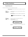
5. Printer functions
Programming mode
The printer is delivered with its menus set to default values at the works.
Should you wish to change a font quality or type, for example, you must go into
programming mode.
What is
programming
mode for?
Programming mode is used to set specific parameters manually via
the control panel.
The "Menu overview" section lists the available menu fields and their
associated options.
J
Getting to
programming
mode
The parameters can be changed either by software instructions
or by making new settings in programming mode.
Change over to off-line mode by pressing the "START" key.
Press the "PROG" key.
The following display briefly appears:
DA615
Inkjet
Programming mode
The printer is in programming mode when the following display
appears:
(Menu field) blinking
\text\etd\DA615\printerf
5.1
(Option field)
DA615 instruction manual
Printer functions
What does the
display show in
programming
mode ?
Menu
The key
functions in
programming
mode
Option
In programming mode, the top line of the key lettering applies (END,
NEXT, PREV, ENTER).
End of programming-mode
Select next value
Change activation between
Menu field and option field
Select previous value
"ENTER" key
This key allows you to change over between displaying the menu field
and the option field. The currently active field blinks. The last status
set is always stored.
"NEXT" key
This key allows you to move to the next possible contents of the active
field.
"PREV" key
This key allows you to move to the previous contents in the active
field.
"END" key
This key allows you to leave programming mode and return to normal
mode.
\text\etd\DA615\printerf
5.2
DA615 instruction manual
Printer functions
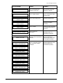
Menu overview
MENU
OPTION
SETTING
No 0 No 1 ... No 9
FONT
Cour12 Cour12bo Cour12it Helv07 Helv10 Helv12 Helv12bo
Helv12it Helv13 LetGot12 TmsRm12 Bru12 OCR-A
PRINT QUALITY
450D 600D 300D 300F 150D 200D
LEFT MARGIN
0
...
304 [mm] 0
TOP MARGIN
0
...
50 [mm] 0
TYPE OF BARC.
off
zip
...
...
11.9 [inch]
1.96 [inch]
bpo4 kix
cana
BARC. OPTIONS
off zip4 dpbc
BARC. POSITION
top bot
2/5i coda co39
c128
SMALL WIDTH (dots)
1 ... 6 ... 99
LARGE WIDTH (dots)
1 ... 15 ... 99
BARCODE HEIGHT (dots)
0 1 2 ... 89 90
CHAR. HEIGHT
1x 2x 3x 4x 5x 6x
CHAR. WIDTH
1x 2x 3x 4x 5x 6x
LINE SPACING
1 2 ... 6 ... 10
ORIENTATION
REV NOR
PAPER SIZE
USER
Maximum values
[mm]
[inch]
off EXEC LETT LEGA A4 A5 MONA C10
INTD C5 INSD C6 A6 CRD1 CRD2 HAGA B5
762
30.0
CHARACTER SET
USA7 UK7 Fra7 Ger7 Ita7 Spa7 Den7 Nor7
SwN7 Por7 PC8 Rom8 P850 ECMA P8DN
P852 P860
TRANSP. DIRECT.
def opp
HEAD12 CORRECT.
-24 -23 -22 -21 ...-2 -1 0 1 2... 21 22 23 24
HEAD34 CORRECT.
-24 -23 -22 -21 ...-2 -1 0 1 2... 21 22 23 24
FIRST UNIT
1+2 3+4
DISTANCE HD2_3
-48 -47 -46 -45 ...-2 -1 0 1 2... 45 46 47 48
PAPER SPEED
mm/s // inch/s
USER
PAP SPEED [Hz]
1
1 ... 50 ... 999
CHAR. SPACING
PAP. LENGTH
ean1)
Swe7
ICEL
NOTE ! Conversion required see Page 6 !
MAX
FAST
MED
1439 // 56.6 1207 // 47.5 889 // 35.0
SLOW
MIN
688 // 27.0
370 // 14.5
1 - 6800
PAPER SENSOR
on off
SETTING LOCKED
no yes
) EAN barcode for European printers / UPC barcode for US printers
\text\etd\DA615\printerf
5.3
DA615 instruction manual
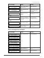
Printer functions
MENU
OPTION
SPECIAL FUNCT.
BIT8 SET TO
BIT8 FIX0 FIX1
AUTO LF
off on_1 on_2 on_3
HEX TO ASCII
off on
LINE MODE
off 0 1 ... 99
DELIMITER < >
off on
STX-ETX
off on
OFFS. EDGE [mm]
0
WARMING
off lev1 lev2 lev3 lev4 max
PAPER TIME-OUT
on off
SPEED REDUCT.
off 5% 10% 15% 20%
SERIAL INTERF.
...
304 [mm]
PC DISP
HANDSHAKE
DTR both XON
BAUDRATE
9600 4800 19K2
DATA LENGTH
8Bit 7Bit
PARITY
no even odd
STOPBIT
1 2
SERVICE
Rev. Adrc Head Char HexD InpD SetD
HARDWARE TEST
-- For service use only ! --
HEAD RESET
all Hd.1 Hd.2 Hd.3 Hd.4 no
The underlined values are default settings
Explaining the menu fields
Setting
Selection of user configurations.
If you wish to use the DA615 in certain applications, it may be necessary
to change some menu settings. You may set up various configurations
yourself and store them in the "Setting" menu.
Nine of the 10 options, namely "No 1" - "No 9", are available for your
own configuration.
The first option, "No 0", is reserved for the default setting.
If you select this option, programming mode is terminated immediately
after you press the "ENTER" key. No further changes can then be made
in this configuration.
To make changes in your configuration, you must first select one of the
remaining nine options ("No 1" to "No 9").
When programming mode is terminated, the changes made are
automatically stored in the selected "Setting No".
\text\etd\DA615\printerf
5.4
DA615 instruction manual
Printer functions
You can lock the setting you have made immediately by using the “A/∀“
key to call the “SETTING LOCKED“ option and selecting between “yes“
and “no“ with the same key.
The set configurations are retained when the printer is switched off.
In the "SetD" option in the “Service” menu you can print out the active
configuration (see "Service" description).
After a works initialization via the "PROG" key (at switch on) all
configurations are set to the default setting.
Selecting individual menu options.
Page down the menu until you get to the option you want. Press the
“A/∀“ key. The following message will appear on the display:
Menu field
Local locked : NO blinking
Option field
Use the PREV, NEXT or
keys to select between the options
"YES" and "NO".
When you select the "YES" option, "(L)" appears in the second line of
the display:
Menu field
(L)
Option field
In the sample print-out of the “SetD" service program on page 5.13, for
example, "ORIENTATION : REV" and "PAPER SIZE : A4" are marked
as “local locked“.
You may also change local locked statuses when the setting is locked.
The following menu options can be individually locked:
FONT
PRINT QUALITY
LEFT MARGIN (mm)
TOP MARGIN (mm)
NOTE !
TYPE OF BARC.
CHAR. SPACING
CHAR. HEIGHT
CHAR. WIDTH
LINE SPACING
ORIENTATION
PAPER SIZE
CHARACTER SET
Locking of settings may lead to incompatibilities with software
applications.
EXAMPLES:
When you lock the left margin, the application program may
implement absolute horizontal positions.
Other conflicts may also occur.
\text\etd\DA615\printerf
5.5
DA615 instruction manual
Printer functions
Fonts
In selecting your fonts, refer to the section entitled “Fonts”. Thirteen
different fonts are installed in the printer. If more fonts are present,
only the first 25 are shown. The following sequence is observed:
works fonts
soft fonts.
Print Quality
You may select between six print qualities:
The numbers specify the number of print dots per character.
The higher the number, the better the print quality.
600D
450D
300D
300F
200D
High print quality
150D :
Low print quality
Slow print
Left Margin
Fast print
This menu allows you to set the spacing between the printing area and
the first printed character in the range between 0-304 mm.
When the PREV/NEXT key is pressed continuously, the change is
performed in cm-steps, otherwise in mm-steps.
Top Margin
This menu allows you to set the spacing between the paper edge and
the first printed line in the range between 0-50 mm.
When the PREV/NEXT key is pressed continuously, the change is
performed in cm-steps, otherwise in mm-steps.
Type of
barcode
Use this menu to select a barcode.
The following barcodes are available:
ZIP barcode
bpo4 barcode
kix barcode
cana barcode
2/5 interleaved barcode
coda barcode
co39 barcode
c128 barcode
ean barcode
If you acknowledge the "ZIP" barcode with the ENTER key, you will be
offered the following parameter setting:
" BARCODE OPTIONS: off "
BARCODE
OPTIONS
(Only for USA !)
\text\etd\DA615\printerf
You may select between the options "off", "zip" and "dpbc".
In the setting "ZIP" the nine (or five) digits of the postal code from the
"ZIP line" are recognized and the corresponding barcode (with check
sum) is printed. The line with the "DLE" sequence (see interface
description - Sect. 8 Zip barcode) in the addressing is then obviated.
5.6
DA615 instruction manual
Printer functions
The numbers of the postal code should be sent in the last line of the
address. The postal code cannot have more than nine digits, but must
have at least five. As the number sequence search starts from the end
of the address, the last nine digits of a sequence are converted. You
may add a separating hyphen or other printable character between the
fifth and sixth digits.
At the "DPBC" setting, the program searches for the house number at
the start of the street line and adds it to the ZIP barcode.
The street line must be sent to the printer before the line containing the
postal code. The house number should be at the beginning of the line.
Where the house number consists of three digits, only the last two are
converted into barcode. House numbers consisting of only a single digit
are preceded by a 0.
BARCODE
POSITION
After you acknowledge your choice in the "BARCODE OPTIONS"
menu field, the following display appears:
"BARCODE POSITION : top"
The ZIP barcode position can be defined by the options "top" or "bot".
These define the position of the ZIP barcode within the address block.
The following variants are possible:
top:
bottom:
Other barcodes
the barcode line is printed as the first address line.
the barcode line is printed after the last address line.
If you acknowledge barcode "2/5i", "coda", "co39" or “c128” with the
ENTER key, you will be offered the following parameter setting:
"SMALL WIDTH : 6"
SMALL WIDTH
You can set the width of the narrow bar from 1 to 99 (dots).
LARGE WIDTH
After you have acknowledged your setting in the "SMALL WIDTH"
menu field, the following appears:
"LARGE WIDTH : 15"
You can now set the width of the thick bar from 1 to 99 (dots).
BARCODE
HEIGHT
After you have acknowledged your setting in the "LARGE WIDTH"
menu field, the following appears:
"BARCODE HEIGHT : 50"
You can now set the height of the barcode from 1 to 999 (dots).
☞
Other barcodes
\text\etd\DA615\printerf
A maximum of 50 dots can be printed with a single traverse
of the print-head.
If you acknowledge the barcode "ean" with the ENTER key, then you
will be offered only the parameter setting "BARCODE HEIGHT" - as
already described.
5.7
DA615 instruction manual
Printer functions
Char. Spacing
You can change the character spacing from 0 to 90 dots by inserting
additional blanks.
Char. Height
You can increase the character height to up to six times the standard
height without changing the width.
Char. Width
You can increase the character width to up to six times the standard
width without changing the height.
Line Spacing
You can change the spacing between the lines from 1 to 10 lines per
inch.
Orientation
The address block may be rotated by 180°.
In "Nor" mode, the address is printed in reverse.
In "Rev" mode, the address is printed in legible form.
Paper Size
You may select any of the following format sizes:
Format
Meaning
off
No format size
EXEC
Size in inches
Width x length**
Size in mm
Width x length**
--
--
--
Executive
P
71/4 x 101/2
184 x 267
LETT
Letter
P
81/2 x 11
216 x 279
LEGA
Legal
P
81/2 x 14
216 x 356
A4
DIN A4
P
81/4 x 1111/16
210 x 297
A5
DIN A5
P
513/16 x 81/4
148 x 210
MONA
Monarch
K
37/8 x 71/2
98 x 190,5
C10
Com-10 (Business)
K
41/8 x 91/2
105 x 241
INTD
International DL
K
411/32 x 821/32
110 x 220
C5
International C5
K
63/8 x 91/64
162 x 229
INSD
Inserter DL
K
41/2 x 91/64
114 x 229
C6
International C6
K
41/2 x 63/8
114 x 162
A6
DIN A6
P
41/8 x 513/16
105 x 148
CRD1
Card 1
Kt
4x6
102 x 152
CRD2
Card 2
Kt
5x8
127 x 203
HAGA
Hagaki
K
315/16 x 513/16
100 x 148
K
615/16 x 927/32
176 x 250
P
max. 30
max.
B5
USER
The format width
is entered in mm
P/E/
Cd*
762
* P = Paper / E = Envelope / Cd = Card
** The values printed in bold are the lengths in the direction of transport
\text\etd\DA615\printerf
5.8
DA615 instruction manual
Printer functions
Character Set
National character sets are available with their own special characters
in each language (see character sets in the Annex).
Transport
Direction
Change of media transport direction
Def. (from right ➔ left)
Opp. (from left ➔ right).
The transport direction can be changed only if you replace the holddown sets (cf. Section 3).
The default setting of the transport direction is from right to left.
Head12 Correct.
This function allows a mechanical horizontal offset between the two
print cartridges 1 and 2 to be corrected. The correction is performed in
1
steps of /300 inch.
Select one of the following 49 values :
-24, -23 ... -5, -4, -3, -2, -1, 0, +1, +2, +3, +4, +5 ... +23, +24
Head34 Correct.
This function allows a mechanical horizontal offset between the two
print cartridges 3 and 4 to be corrected. The correction is performed in
1
steps of /300 inch.
Select one of the following 49 values :
-24, -23 ... -5, -4, -3, -2, -1, 0, +1, +2, +3, +4, +5 ... +23, +24
First Unit
This menu allows you to select the print cartridge block which –
depending on the transport direction – prints lines 1 to 6.
H12 for transport direction of the media from right to left
H34 for transport direction of the media from left to right
Paper Speed
The maximum transport speed for each print quality may be set.
Paper Sensor
End-of-form detection on/off.
When the end-of-form detection function is activated, the light barrier is
interrogated before every line is printed as to whether paper is present
in the print area.
For printing media with black surfaces, you can deactivate the light
barrier during printing. To do this, you must set a format size in the
“PAPER SIZE“ menu (see page 5.8).
When the end-of-form detection is deactivated and a format size has
been specified, the light barrier is interrogated as to whether paper is
present in the print area only when the paper is fed in.
☞
\text\etd\DA615\printerf
An incorrect format size can lead to printing outside the
paper area!
5.9
DA615 instruction manual
Printer functions
Setting locked
You may "lock" each configuration individually. This means that the
corresponding configuration cannot be changed via printer instructions.
If you select the "yes" option, your configuration is locked and the
corresponding printer instructions are ignored. In the “SETD“ service
program, this setting is clearly identified by “!!!“ (see the sample print-out
on page 5.13).
The status of the active configuration is shown on the display.
The display text "Set1U" means that configuration "No 1" was selected,
but is Unlocked.
The display text "Set1L" means that configuration "No 1" was selected,
but is Locked.
Special Funct.
Bit8 Set To
This menu allows you to define how the DA615 should execute bit 8.
This menu option is active only for 7-bit character sets.
The following variants are possible:
BIT8:
FIX0:
FIX1:
Auto LF
The higher-value bit (bit 8) of the received character is taken
over in unchanged form.
The higher-value bit (bit 8) of the received character is always
deleted.
The higher-value bit (bit 8) of the received character is always
set to "1".
Automatic line feed off / on_1 / on_2 / on_3
Use this menu to define how the DA615 should interpret the following
control characters:
and
CR =
LF =
FF =
Carriage return
Line feed
Form feed.
The following variants may be selected:
off :
on_1:
on_2:
on_3:
Hex to ASCII
CR = CR,
CR = CR + LF
CR = CR,
CR = CR + LF
LF = LF,
LF = LF
LF = CR + LF
LF = CR + LF
FF = FF
FF = FF
FF = CR + FF
FF = CR + FF
HEX to ASCII conversion off/on
When the conversion is switched on, the printer interprets the percentage symbol "%" as a non-printable control character. The two characters following the % symbol are then interpreted as HEX values and
combined into a single character.
Example: %0C = Form Feed
Line Mode
Line mode off / 1 - 99 lines
This option allows address separation by a specific number of line
feeds.
If the PREV/NEXT key is kept continuously pressed, the change takes
place in steps of 10, otherwise in steps of 1.
\text\etd\DA615\printerf
5.10
DA615 instruction manual
Printer functions
Delimiter < >
Individual page feed on/off
When the delimiter is activated, the two print characters "< >" are
recognized as the beginning and end of a page print with paper ejection.
This means that you should set the character "<" before a piece of text
that should go onto a new page and the character ">" after the text,
before the page is to be ejected.
STX-ETX
Print-out of a specific text area off/on
With this mode activated, only the text located between STX and ETX
will be printed.
STX = Start text
Offset Edge
ETX = End text
Offset edge of page by 0 – 304 mm
This function shifts the measured edge of the paper. To the user, it will
look as if the left margin had been increased.
This option is required for:
Warming
–
Windows programs in which the left edge cannot be changed (or
this is not desired).
–
Printing of large envelopes with Windows serial print, where the
desired print position cannot be set on the PC.
Warming the print cartridges
This function sets the time during which the cartridges are warmed.
min. lev1 lev2 lev3 lev4 max.
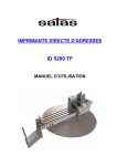
Service
Rev.
(=Revision)
The version number of the firmware is displayed together with the
prom number of the paper transport controller. Both numbers must be
specified if problems occur with the printer.
Adrc
Display of printed addresses from the initial operation of the printer.
This counter can be reset only by service personnel.
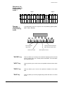
Head
Several print tests are performed for all cartridges:
– the contacts to the nozzles are displayed in a grid pattern,
H1 = Head 1
H3 = Head 3
H1
1
5
10
15
20
3 5
10
15
20
12
H3
1
\text\etd\DA615\printerf
5
10
5.11
15
20
3 5
10
15
20
12
DA615 instruction manual
Printer functions
H2 = Head 2
H4 = Head 4
1
5
10
15
20
3 5
10
15
20
12
H2
1
5
10
15
20
3 5
10
15
20
12
H4
–
the contacts to all nozzles, addressed individually in sequence, are
displayed in a continuous oblique line.
H1
H2
H3
H4
Char
Print-out of the currently defined character set.
HexD
Hex Dump causes all received characters to be printed from the
receive buffer in LetGot12.
Hex Dump is terminated with the PROG, END or START keys.
☞
InpD
In Inp-Dump, all 96 kbytes of the receive buffer are printed with PC8
symbols.
NOTE !
SetD
Hex Dump may also be initiated directly by keeping the START
key pressed down when the printer is switched on. Do not
terminate Hex Dump by switching off the printer as this may lead
to changes in the settings!!
The entire print-out requires about 30 DINA4 pages. Switch the
printer off and then on again, send the print job and then start the
dump print-out. The required data is now located at the beginning
of the buffer. As soon as it has been printed out, you may stop
further printing.
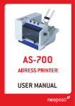
The 10 printer settings that are activated under each number in the
“Setting” option are printed out.
To do this, you will need nine sheets with minimum dimensions (LxW)
160 x 50 mm (6.3x2“). They are not pulled in until after the “SetD“
instruction has been given.
The following page shows a complete SetD print-out.
\text\etd\DA615\printerf
5.12
DA615 instruction manual
Printer functions
DA615
\text\etd\DA615\printerf
SETTING
No 1
No 2 ...
No 0
FONT
PRINT QUALITY
Cour12
600D
Helv10
600D
Cour12
300D
LEFT MARG. [mm]
TOP MARGIN [mm]
10
0
20
10
0
0
TYPE OF BARC.
BARC. OPTIONS
BARC. POSITION
SMALL WIDTH
LARGE WIDTH
BARCODE HEIGHT
zip
off
top
-
2/5i
6
15
50
ean
50
CHAR. SPACING
CHAR. HEIGHT
CHAR. WIDTH
0
1x
1x
0
1x
1x
0
3x
2x
LINE SPACING
ORIENTATION
PAPER SIZE
PAP LENGTH [mm]
CHARACTER SET
TRANSP. DIRECT.
6
Rev
A4
PC8
def
HEAD12 CORRECT.
HEAD34 CORRECT.
FIRST UNIT
DISTANCE HD2_3
PAP SPEED mm/s
PAPER SENSOR
SETTING LOCKED
HEAD SENSOR
SEPARATION
BIT8 SET TO
AUTO LF
HEX TO ASCII
LINE MODE
DELIMITER < >
STX-ETX
OFFS. EDGE[[mm]]
WARMING
PAPER TIME-OUT
SPEED REDUCT.
SERIAL INTERF.
HANDSHAKE
BAUDRATE
DATA LENGTH
PARITY
STOPBIT
-2
-2
1+2
0
MIN=370
on
yes
!!!
on
min
Bit8
off
off
off
off
off
0
off
on
10%
PC
DTR
9600
8Bit
no
2
EMULATION
MACRO
DL FONT
INK COUNTER 1
INK COUNTER 2
INK COUNTER 3
INK COUNTER 4
ADDRCOUNTER
RAM
REVISION
PCL3
32333[H=4]
no
99%
98%
94%
92%
1581
Expanded [4MByte]
V3.30 #2763
5.13
(L)
(L)
Nor
User
237
PC8
def
Rev
off
PC8
opp
-1
-1
3+4
-1
MED=889
on
no
on
lev12
Bit8
on_1
off
off
off
on
0
lev_1
on
30%
PC
DTR
9600
8Bit
even
2
0
0
1+2
0
FAST=1207
on
no
on
min
Bit8
off
off
off
off
off
0
max
off
20%
PC
XON
19K2
8Bit
even
2
DA615 instruction manual
Printer functions
Hardware Test
Testing of various hardware components.
(For service personnel only!)
Head Reset
Resets the ink counter after a new cartridge has been inserted (see
page 4.1).
Example of an application in programming mode
You want to set up a configuration whose line spacing is changed from
6 lines/inch to 8 lines/inch.
Switch the printer on.
Programming mode
Press the "PROG" key.
Activate required
menu field
Use the "PREV" or "NEXT" keys to move to the desired "Line spacing"
menu field. The blinking menu field is activated.
Changing from menu Press the "ENTER" key. The option field (= 1 line to the right) blinks.
field to option field
Activate required
option field
Use the "PREV" or "NEXT" keys to move to the desired option field
"8". The blinking option field is activated.
End programming
mode
Press the "END" key. The new value is now stored in the configuration
under the selected "Setting No" and the printer is in off-line mode
again
or
Press the "START" key. The printer is now in on-line mode again and
is ready to continue the print job.
Initializing the printer
without loss of
configuration
To get to the default configuration, select option "No 0" in the "Setting"
menu field in programming mode. To end programming mode, press
the "ENTER" key. The "Set 0U" message appears on the display. The
set configurations are stored under their respective setting numbers
(cf. "Setting" menu).
with loss of
configuration
To return all the changed values and configurations to their original
settings, switch the printer off.
Keep the “PROG" key pressed down when switching the printer
on again.
The display shows
DA615
Inkjet
Default Reset
The printer now has the default settings and all configurations as set at
the works. The display shows "Set 1U”.
\text\etd\DA615\printerf
5.14
DA615 instruction manual
5.
Printer functions
Programming mode
What is programming mode for?
Getting to programming mode
What does the display show in programming mode ?
The key functions in programming mode
Menu overview
5.1
5.1
5.1
5.2
5.2
5.3
Explaining the menu fields
Example of an application in programming mode
Initializing the printer
\text\etd\DA615\printerf
5.1
5.0
5.4
5.14
5.14
DA615 instruction manual
6. Interfaces
The DA615 printer is equipped with two standard data communications interfaces.
The interface connection sockets are:
- Centronics parallel
- RS-232-C serial
Both of them allow connection of the printer to the terminal or the
computer.
Centronics parallel interface
The DA615 printer is equipped with a standard Centronics parallel
interface. This interface is most frequently used for connecting to a
personal computer. In contrast to the RS-232-C serial socket, it usually
requires no special instructions or configurations for the printer or
computer. In addition, the Centronics parallel interface cable allows
faster data transmission.
The parallel interface connector has a standard 36-pin Amphenol
socket with two metal clips.
Connecting socket
Connector type:
Amphenol socket strip
Design: 57 - 40360
Cable length max. 2 m with Amphenol
plug strip 57 - 30360
The signal description is given on the next page.
\text/etd/DA615\Interfaces
6.1
DA615 instruction manual
Interfaces
Signal description
PIN
\text/etd/DA615\Interfaces
Associated
GND
1
19
2-9
20-27
10
Signal
Signal-
Meaning
Input/Output
________
STROBE
E
This pulse (0.5µs)
reports that data
bits are valid
DATA 1-8
_____________
E
Data bits D0-D7
28
ACKNOWLEDGE
A
Printer report:
data are processed
(ready to receive)
11
29
BUSY
A
Printer report:
data received,
data being processed
12
30
PE (Paper empty)
A
Printer reports to
computer: no
paper
13
--
SELECT (Online)
A
Signal is high when
printer is on-line
14
--
Autofeed
E
No function, only
for bidirectional
interface
15
--
Free
Free
16
--
GND
GND
17
--
Chassis GND
Chassis GND
18, 35
--
+ 5V
+ 5V over 0.2A Si
19-30
--
GND
31
--
32
--
GND
____
INIT
_______
ERROR
33
--
GND
GND
34
--
Free
Free
36
--
SELECT IN
6.2
E
Resets printer
A
Signal is low at
printer error
E
No function, only
for bidirectional
interface
DA615 instruction manual
Interfaces
Pulse diagram
DATA 1 - 8
________
STROBE
BUSY
_______________
ACKNOWLEDGE
\text/etd/DA615\Interfaces
6.3
DA615 instruction manual
Interfaces
RS-232-C serial interface
The DA615 printer has a standard RS-232-C serial interface that is compatiblewith
with most computers and terminals.
Connecting
socket
Pin assignment
The DA615 printer is equipped with a standard DB-9 serial connection
socket.
PIN
Signal
SignalInput/Output
Meaning
1
---
-
Free
2
Rxd
E
Receive data
3
Txd
A
Transmit data
4
DTR
A
Clear to receive
5
GND
-
Signal ground
6
---
-
Free
7
RTS
A
+12V
8
CTS
E
Clear to send
9
---
-
Free
Pin 2
Received Data (RxD):
Serial data transfer from computer to printer.
Pin 3
Transmitted Data (TxD):
Serial data transfer from printer to computer system or terminal (e.g.
XON/XOFF characters).
Pin 4
Data Terminal Ready (DTR):
Printer output that clears data transfer to the printer or aborts it
(handshaking). Data transfer is possible when DTR is high. It is not
possible when DTR is low.
Pin 5
Signal Ground (GND):
This is the reference potential for the entire data exchange.
Pin 7
Request to Send (RTS):
This signal is always high when the printer is switched on.
Pin 8
Clear to Send (CTS):
Printer input that clears or aborts data transmission to the computer.
When the input is high, the printer can transmit data. This input must
always be high for software handshaking with Xon/Xoff.
\text/etd/DA615\Interfaces
6.4
DA615 instruction manual
6.
Interfaces
6.1
Centronics parallel interface
Signal description
Pulse diagram
6.2
6.3
RS-232-C serial interface
\text/etd/DA615\Interfaces
6.1
6.0
6.4
DA615 instruction manual
7. Fonts
Terminology
A font is a collection of characters and symbols with the same font type and
spacing, the same size (height), line thickness and character position
Font type
A font type is a set of characters and symbols of a specific design.
Cour
Helv
TmsRm
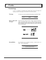
Serif or sans serif
font type
Serifs are small cross-lines above or below characters (known as
"feet" in the Antiqua fonts). Cour is a Serif font type. Font types
without serifs are known as Sans Serif. Helv is a Sans Serif font
type. The diagram below shows the difference between a Serif and
a Sans Serif font type.
Normal/italics
The characters can be printed out either in normal mode or in
italics - with a constant slope.
This line is printed with normal characters.
This line is printed in italics.
\text\etd\DA615\font
7.1
DA615 instruction manual
Fonts
Spacing
Fixed spacing
Spacing refers to the relative print density between the letters of a
font. The character spacing is either fixed or proportional.
With fixed character spacing, each letter of a font assumes the
same width and has the same spacing to the adjacent letters. Cour
and LetGot are fonts with fixed spacing.
Fixed spacing between
characters
Proportional
spacing
With proportional character spacing, the spacing depends on the
width of each letter. Helv and TmsRm are examples of fonts with
proportional spacing.
Proportional character spacing
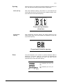
Pitch
The pitch depends on the number of printed characters within a
linear inch. A font with a pitch of 10 cpi prints 10 characters per
horizontal inch (cpi = characters per inch). The pitch can be
specified only for fonts with fixed spacing.
12 characters per inch (12
cpi)
10 characters per inch (10
cpi)
0
\text\etd\DA615\font
1
7.2
(inch)
DA615 instruction manual
Fonts
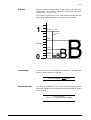
Dot size
Dot size (character height) refers to the height of an upper-case
printed latter. The dot size is measured in pica points. One point
corresponds to 1/72 of an inch.
The heights of both types of font, those with fixed and those with
proportional character spacing, are measured in pica points.
1
72 dot s = 1 i nch
Pica dot
48 dots
(inch)
24 dots
12 dots
8 dots
0
Underlining
A piece of text may be highlighted by underlining. The otherwise
uniform typeface remains unchanged.
You can underline a single word.
Expanded mode
You can print the address (e. g. for large goods packages) twice as
wide while maintaining the proportional character width with respect
to the spacing.
This is normal width
Thi s i s expanded wi dt h
\text\etd\DA615\font
7.3
DA615 instruction manual
Fonts
Character spacing
To bring single words out more clearly, you can expand the spacing
between letters and words without changing the character size
itself.
This E x a m p l e is printed with expanded
spacing.
Quality
The term quality refers to the quality of the printout.
150D
Use 150D for fast printing with low ink consumption. This
corresponds to a pitch of 150x150 dpi (dots/inch).
300F
Use 300F for your standard correspondence. This mode makes
use of the maximum pitch of 300 dpi (dots/inch).
600D
Use 600D to obtain an enhanced appearance for your
correspondence. This mode makes use of the maximum pitch
of 600x600 dpi (dots/inch).
Orientation
Orientation refers to the (readable) address position on the paper. It
may be rotated by 180°.
Note the specifications relating to image memory capacity in the
“Orientation“ menu on page 5.8.
\text\etd\DA615\font
7.4
DA615 instruction manual
Fonts
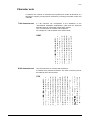
Character sets
A character set consists of characters and symbols that contain all elements of a
language or subject (country-specific characters), including punctuation marks and
numerals.
7-bit character set
A 7-bit character set corresponds to the definitions of the
"International Standards Organization" (ISO) and the 'American
Standard Code for Information Interchange' (ASCII).
The 7-bit character set contains 128 characters.
An example of a 7-bit character set is shown below.
USA7
8-bit character set
The 8-bit character set contains 256 characters.
It includes many national characters. The most commonly used 8bit character set is shown below.
PC8
\text\etd\DA615\font
7.5
DA615 instruction manual
Fonts
Selecting fonts for your addresses
☞
The fonts are selected either by software or by printer
commands.
Fonts can be used selectively to give an address a specific
appearance.
Select the fonts that correspond to the message that you want your
document to express.
Serif fonts
The example below shows an address using Cour12 font:
Dr.
Lemuel Gulliver
104 Churchill St.
Cambridge CB8 5TD
Sans serif
fonts
The example below shows an address using Helv12 font:
Dr.
Lemuel Gulliver
104 Churchill St.
Cambridge CB8 5TD
\text\etd\DA615\font
7.6
DA615 instruction manual
7.
Fonts
7.1
Terminology
7.1
Font type
Serif or sans serif font type
Normal/italics
Spacing
Pitch
Dot size
Underlining
Expanded mode
Character spacing
Quality
Orientation
Character sets
7.5
7-bit character set
8-bit character set
7.5
7.5
Selecting fonts for your addresses
\text\etd\DA615\font
7.1
7.1
7.1
7.2
7.2
7.3
7.3
7.3
7.4
7.4
7.4
7.0
7.6
DA615 instruction manual
8. Error messages and hints
General error messages
Error message
Cause
Solution
ERROR LCA !!
CALL SERVICE
Error in loading the
hardware into the XC5206
module.
ERROR LCA# Ready
CALL SERVICE
Printing error – the
XC5206 module does not
confirm successful
completion of the print
operation.
- Check the connection on
or to the print board.
- Check the module
XC5206
- Check the print-head.
- Check that the correct
firmware was loaded.
# = Number 1-4 specifies which module
is responsible for this error.
NO PAPER !!
Paper has run out.
Insert new paper
PAPER JAM !!
REMOVE PAPER
Paper is jammed.
Remove jammed paper and
readjust the paper feed
mechanism (see Sect. 3).
The printed area is
– Check the light barrier.
outside the paper format. – Reduce the "Top margin"
setting with the "ð
ð" key or
– The light barrier for paper
in programming mode, or
detection is not working
correct the paper size (see
properly.
Sect. 5).
– Check the paper for black
areas.
POSITION ERROR !!
CHECK TOP MARGIN
–
NO INK !!
CHANGE PRINTHEAD
The cartridge is empty.
Replace the cartridge (see
Sect. 4).
CHECKSUM ERROR !!
MAKE DEFAULT RESET
Error in the buffered
RAM (module M48Z58).
–
Reset to default value (see
Sect. 5).
– Replace module M48Z58.
CHECKSUM ERROR !!
MAKE COUNTER RESET
CHECKSUM ERROR !!
TESTMACRO RESET
CHECKSUM ERROR !!
SETTING RESET
\text\etd\DA615\Error
8.1
DA615 instruction manual
Error messages and hints
Error message
Cause
Solution
TEST MACRO TOO LONG
The user-defined test
address is too long.
Limit the size of the test
address to 3 Kbytes.
BUFFER OVERFLOW !!
Error in data transfer.
Check connections of the
interface cable.
Error in the Flash prom.
Reload the RENA fonts.
EPROM ERROR !!
VERIFY FONT
Reload the program
(firmware).
EPROM ERROR !!
VERIFY PROG
RAM ERROR !!
VERIFY RAM
PROGRAM ERROR !!
MAKE DEFAULT RESET
UNPRINTED ADDRESSES !
FINISH THE JOB
PIC ERROR
VERIFY CONTROLLER
Error in RAM.
Arrange for the CPU board
to be replaced by service
personnel.
Error in program
execution.
- Perform a default initialization (Sect. 5)
- Reload the firmware.
Address was not printed to Make no changes in
the end.
programming mode when
the print job is running!
Error in controller module
that controls the paper
transport.
- Check module PIC 1665.
- Set the paper feed
mechanism properly.
PIC TIME OUT
VERIFY CONTROLLER
PIC STATUS ANSW.
PAPER OUT (PAP)
PIC CALL
PROGRAM ERROR
TIME OUT PIC
WAITING FOR PAPER
PIC CODE
PAPER OUT (PAP)
IBF ERROR
VERIFY CONTROLLER
PIC OBF ERROR
PAPER OUT (PAP)
\text\etd\DA615\Error
8.2
DA615 instruction manual
Error messages and hints
Error message
Cause
Solution
UART TIMEOUT
CALL SERVICE
Error in UART module
(serial interface).
Replace CPU board.
DISPLAY TIMEOUT
CALL SERVICE
Error in addressing the
display
–
Cartridge No. # is not
inserted.
Insert the missing cartridge
(see Sect. 4).
CHECK CARTRIDGE #
Check cable connections
– Replace display unit if
necessary
# specifies the number of the missing
cartridges
CHECK CARTRIDGES #,#
## specifies the number of the missing
cartridges
Insert both missing
One pair of cartridges is
not inserted. #,# stands for cartridges (see Sect. 4).
1,2 or 3,4.
CHECK ALL CARTRIDGES
No cartridge is inserted.
Insert all 4 cartridges (see
Sect. 4).
CHECK THE CARTRIDGES
Some cartridges are not
properly inserted.
Insert the missing cartridges
(see Sect. 4).
Error messages for soft fonts
Error message
FONT LOADING
ERROR: TIMEOUT
Cause
Solution
Error in download font.
Check download font.
Error in loading the font:
insufficient memory
Font no longer fits into the
memory
Error in download font
Check download font
FONT LOADING
ERROR: HEADER (SB)
FONT LOADING
ERROR: HEADER (F)
FONT LOADING
ERROR: FONT ORIENT
FONT LOADING
ERROR: CHAR. HEADER
FONT LOADING
ERROR: MEMORY (RAM)
FONT LOADING
ERROR: CHAR. NO.
\text\etd\DA615\Error
8.3
DA615 instruction manual
Error messages and hints
Error message
FONT LOADING
ERROR: SUPPL. CHAR.
Cause
Solution
Error in download font
Check download font
Error in loading the macro:
insufficient memory
Macro no longer fits in the
memory
FONT LOADING
ERROR: CHAR. LasFt
FONT LOADING
ERROR: DATA LasFt
FONT LOADING
ERROR: CHAR. HEIGHT
FONT LOADING
ERROR: DL DISABLED
MACRO LOADING
ERROR: MEMORY (RAM)
In some error messages, from Rev. 4.5, a number is displayed in the top right
corner. This number must be specified in the event of all error messages.
Notes on maintenance
Ensure that the contact wheels and rollers are kept clean at all times
\text\etd\DA615\Error
8.4
DA615 instruction manual
8.
\text\etd\DA615\Error
Error messages and hints
8.1
General error messages
8.1
Error messages for soft fonts
8.3
Notes on maintenance
8.4
8.0
DA615 instruction manual
9. Annex
Page
Technical data
A.1
Character sets
B.1
7-bit character set
B.1
8-bit character set
B.4
Glossary
C.1
Index
D.1
Accessories
E.1
Guide brackets
E.1
Pinwheels
E.2
Paper guide
E.2
Variant list
\text\etd\DA615\annex
9.0
DA615 instruction manual
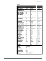
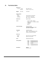
A.
Technical data
Dimensions
L x W x H (mm)
(inches)
Weight
(kg / lbs.)
687 x 281 x 410
27.05 x 11.06 x 16.14.
40 / 88.18
Paper formats
Width
Length
Thickness
From 100 mm / 3.93 inches
From 50 mm / 2.0 inches
Max. 10 mm / 0.393 inches
Paper feed
External feed
Fonts
-
Print technology
Ink-jet technology
Two blocks, each with two inkjet
HP 51645A cartridges
Cartridges
Inkjet HP 51645A
Life
Cour12, 12bold, 12italics
Helv 7, 10, 12, 13, 12bold, 12italics
TmsRm12
LetGot12
Bru12
Approx. 160,000 addresses in fast
quality, 60 characters/address
Print area
Height
Width
\text\etd\DA615\technic
2x25.4 mm / 2x1 inches height
600 mm / 23.6 inches
Pitch
600 dpi (dots per inch)
Print qualities
-
Orientation
Normal
Rotated by 180°
A.1
600D
450D
300D
300F
200D
150D
600 dpi (dots per inch)
450 dpi (dots per inch)
300 dpi (dots per inch)
300 fast
200 dpi (dots per inch)
150 dpi (dots per inch)
DA615 annex
Annex A – Technical data
Codabar
Code 39
C128
2/5 interleaved barcode
EAN industry barcode
Postal barcode for the UK
Postal barcode for the Netherlands
Postal barcode for Canada
Postal barcode for USA
Barcodes
-
Buffer
4 MB
Settings
10 configurations can be stored
Address buffer
Stores the last 20 addresses
Firmware update
Via PC interface in flash proms
Counter
-
Resettable address counter
Life counter
Interface
Parallel
Serial
Centronics compatible
V24, 2400 – 19K2 baud
Power supply
100 - 120V / 220 - 240V
50 / 60 Hz
Fuse (power input)
1 x 2A (slow-acting)
100 - 120V, 230 - 240V
Noise
< 55 db at a distance of 1 m
(ISO 9296)
Options
-
\text\etd\DA615\technic
A.2
Automatic dry band
Stand for height adjustment of dry
band
Stop plate for lateral paper
transport
Hold-down units for changing print
direction with contact rollers
Hold-down units for changing print
direction with pinwheels
Stacker for DIN A4 formats
DA615 annex
A.
\text\etd\DA615\technic
Technical data
A.0
A.1
DA615 annex
B.
Character sets
7-Bit-character sets
ASCII (= USA7)*
ASCII:
Decimal:
Hexadecimal:
England (= UK7)*
ASCII:
Decimal:
Hexadecimal:
*
**
Ec ( 0 U
27 40 48 85
1B 28 30 55
**
Ec ( 1 F
27 40 49 70
1B 28 31 46
**
Frankreich (= Fra7)*
Ec ( 1 E
27 40 49 69
1B 28 31 45
**
ASCII:
Decimal:
Hexadecimal:
The figures in parentheses correspond to the option field names in the DA615
You can use the printer command to call the character set via software.
\text\etd\DA615\character
B.1
Annex DA615
Annex A - character sets
Deutschland (= Ger7)*
ASCII:
Decimal:
Hexadecimal:
Ec ( 1 G
27 40 49 71
1B 28 31 47
Italien (= Ita7)*
**
Spanien (= Spa7)*
ASCII:
Decimal:
Hexadecimal:
*
**
ASCII:
Decimal:
Hexadecimal:
Ec ( 0 I
27 40 48 73
1B 28 30 49
Dänemark (= Den7)*
Ec ( 2 S
27 40 50 83
1B 28 32 53
ASCII:
Decimal:
Hexadecimal:
Ec ( 1 D
27 40 49 68
1B 28 31 44
The figures in parentheses correspond to the option field names in the DA615
You can use the printer command to call the character set via software.
\text\etd\DA615\character
B.2
Annex DA615
Annex A - character sets
Norwegen (= Nor7)*
ASCII:
Decimal:
Hexadecimal:
*
**
Schweden (= Swe7)*
Ec ( 0 D
27 40 48 68
1B 28 30 44
**
ASCII:
Decimal:
Hexadecimal:
Schweden/Namen (= SwN7)*
Portugal (= Por7)*
ASCII:
Decimal:
Hexadecimal:
ASCII:
Decimal:
Hexadecimal:
Ec ( 0 S
27 40 48 83
1B 28 30 53
Ec ( 3 S
27 40 51 83
1B 28 33 53
Ec ( 4 S
27 40 52 83
1B 28 34 53
The figures in parentheses correspond to the option field names in the DA615
You can use the printer command to call the character set via software.
\text\etd\DA615\character
B.3
Annex DA615
Annex A - character sets
8-Bit-character sets
PC-8 (= PC8)*
ASCII:
Decimal:
Hexadecimal:
Ec ( 10 U
27 40 49 48 85
1B 28 31 30 55
**
Ec ( 8 U
27 40 56 85
1B 28 38 55
**
Roman8 (= Rom8)*
ASCII:
Decimal:
Hexadecimal:
*
**
The figures in parentheses correspond to the option field names in the DA615
You can use the printer command to call the character set via software.
\text\etd\DA615\character
B.4
Annex DA615
Annex A - character sets
PC-850 (= P850)*
ASCII:
Decimal:
Hexadecimal:
Ec ( 12 U
27 40 49 50 85
1B 28 31 32 55
**
ECMA-94 Latin 18 (= ECMA)*
ASCII:
Decimal:
Hexadecimal:
*
**
Ec ( 0 N
27 40 48 78
1B 28 30 4E
The figures in parentheses correspond to the option field names in the DA615
You can use the printer command to call the character set via software.
\text\etd\DA615\character
B.5
Annex DA615
Annex A - character sets
PC-8 Dänemark/Norwegen (= P8DN)*
ASCII:
Decimal:
Hexadecimal:
Ec ( 11 U
27 40 49 49 85
1B 28 31 31 55
**
ICEL (= ICEL)*
ASCII:
Decimal:
Hexadecimal:
*
**
Ec ( 33 O
27 40 51 51 79
1B 28 33 33 4F
The figures in parentheses correspond to the option field names in the DA615
You can use the printer command to call the character set via software.
\text\etd\DA615\character
B.6
Annex DA615
Annex A - character sets
PC-852 (= P852)*
ASCII:
Decimal:
Hexadecimal:
Ec ( 17 U
27 40 49 55 85
1B 28 31 37 55
**
PC-860 (= P860)*
ASCII:
Decimal:
Hexadecimal:
*
**
Ec ( 20 U
27 40 50 48 85
1B 28 32 30 55
The figures in parentheses correspond to the option field names in the DA615
You can use the printer command to call the character set via software.
\text\etd\DA615\character
B.7
Annex DA615
\text\etd\DA615\character
B.0
DA615 annex
C.
Glossary
ASCll:
Character spacing
ASCll stands for American Standard Code for
Information Interchange. The printer commands used in this User Guide are entered
with ASCII characters. However, decimal or
hexadecimal characters may also be used.
All fonts have either a constant or a variable
character spacing. In a font with a constant
spacing, all characters have the same width
irrespective of their size. In proportional fonts,
the printed width depends on the actual widths
of the respective characters.
Barcode:
Configuration:
Data information about a print medium is converted into a barcode, a form independent of
language and characters. A barcode is easy to
create and simple to read by opto-electronic
devices. It is printed in addition to information
written in normal text.
A configuration is a set of specific printer settings. Several configurations can be set up and
stored under specific configuration numbers.
Control code:
Baud rate:
See printer command.
This is the speed at which data is transferred
between the computer and the printer via the
serial interface. The computer and printer must
have the same baud rate. It can vary between
1200 and 9600 baud depending on the computer used. The baud rate is specified only if a
serial interface is used.
Control panel:
This comprises the keyboard and the display. It
is used to make all the internal settings for the
printer.
CPl:
Characters Per Inch: the unit of print density.
Bit:
Data transfer:
Binary digit. A bit is the smallest unit of digital
information and can represent only two states,
namely "I" or "O".
The transfer of information between computer
and printer.
Bit map:
Default configuration:
A collection of dots forming text or graphics in
output equipment (printer, monitor).
Before being dispatched, the printer is programmed with standard settings. These are
stored in the „O“ configuration and remain
active until a different configuration number is
selected and the settings are changed.
Buffer:
A buffer is a memory area in the printer. It
stores the input and output information until its
subsequent processing.
Dot size:
The dot size is measured in pica dots. One dot
represents 1/72 of an inch.
Byte:
A memory unit consisting of 8 bits.
DPl:
Character:
Letters, numbers and symbols that can be
printed.
Dots Per Inch: the unit of measurement for the
image definition. The more dots, the sharper
the image.
Character height:
Driver:
The height of an upper-case printed letter. The
dot size is measured in pica dots. One dot is
1/72 of an inch.
See Printer driver.
Escape character:
The escape character EC is an instruction
indicator in ASCII code. This character is not
printed, but the printer recognises the characters following it as instruction code.
Character set:
A character set is defined according to the
application and is usually a combination of
letters, numbers, lines and symbols within a
font. Character sets may, however, consist
only of symbols.
\text\etd\DA615\glossary
Escape sequences:
See Printer commands.
C.1
Annex DA615
Annex C - Glossary
Font:
Paper sensor:
A font is a collection of characters and symbols
of the same print type and spacing, the same
size (height), line thickness and print orientation. Fonts can be installed inside the printer or
loaded externally via font cartridges.
This is required for maintaining the top margin
value and for stopping the printer in the event
of a paper jam. The medium must always be
transported over the paper sensor.
Paper size:
Font cartridges:
This refers to the paper format on which text is
printed. With an address block rotation around
180°, the top margin is automatically calculated
so that it corresponds to the value set for the
normal address-block orientation.
These contain fonts that can be loaded into the
printer.
Handshake:
This refers to the control of the data transfer
between the computer and the printer in order
to protect the printer’s memory buffer from
overflow or loss of data.
Parallel interface:
This is also known as a Centronics interface
and connects the computer to the printer. It
always transfers 8 bits = 1 byte at a time (in
parallel).
Hardware:
The parts of your computer system such as the
computer itself, the keyboard and the printer.
Parity:
The data transfer cable that connects your
computer with the printer or other peripheral.
Parity is an error-detection technique used on
a serial interface. Errors are detected during
data transfer. This involves checking the even
number of binary ones in an information unit
(such as a byte).
Interface connection socket:
PCL instruction
The DA 615 is supplied with two interface
connection sockets, a parallel and a serial one.
Both are located under the paper feed tray
next to the power module. The connection
cable for your computer and printer is connected to this socket.
Printer Control Language is the HP PCL Level
III printer language developed by HewlettPackard.
Interface cable:
Pitch:
The number of printed characters in an inch.
Internal fonts:
Print area:
These fonts are installed in the printer of which
they form a permanent part.
The maximum width accessible to the printer
cartridge.
Line thickness:
Print cartridge:
This refers to the width of barcode lines. Normal and bold thicknesses are available.
The cartridge contains the ink for printing. An
empty cartridge is replaced by a new one of
the same type.
LPI
Lines Per Inch: the unit of line spacing. The
most frequent spacing for printing is 6 Ipi.
Print density:
A measure of image definition. It is measured
in dots per inch (dpi).
Off-line:
In off-line mode, the printer cannot receive any
data from the computer. Settings and programming are then carried out directly on the
printer.
Print orientation:
On-line:
Print type:
In on-line mode, the printer can receive data
from the computer. In this state, the keyboard
is locked except for the START key.
This refers to the print design of a character
set. Thus Cour has a different character design
than LetGot or Helv.
Paper jam:
Printer commands:
A paper jam may occur during printing, with
blockage of paper feed or ejection.
Commands entered via the software application in order to make changes in the active
printer configuration.
\text\etd\DA615\glossary
The characters can be printed either upright
(normal) or as italics with a constant angle.
C.2
Annex DA615
Annex C - Glossary
Printer driver:
The driver converts the printer commands
entered via software into instruction codes for
the printer. It must be adapted to both the
software and the printer.
Print-head cradle:
The print head is attached to a movable cradle.
Print-head holder:
This holds the print head securely in place.
Print-head spacing:
This affects the print quality. If the spacing is
too big, the print is unclear. If it is too small, the
ink can smudge.
Sans Serif font:
A font type with no horizontal lines on the head
or foot of a letter. This text is printed in a Sans
Serif font, for instance.
Separators:
Separators allow single-sheet feed from a
media stack. The lowest sheet is drawn in first.
Serial interface:
In a serial interface, the data are transferred
successively (bit by bit) from the computer to
the printer. The connection is set up via an RS232-C socket.
Serif font:
Serifs are the „feet“ on the Antiqua fonts. Cour
is a serif font, for example.
Setting:
Selecting configurations.
Soft fonts:
Soft or download fonts are stored on floppy
disk. They can be loaded into the printer memory.
Software:
The various programs installed in your computer system, including operating and graphics
programs or special application packages.
\text\etd\DA615\glossary
C.3
Annex DA615
C.
\text\etd\DA615\glossary
Glossary
Fehler! Textmarke nicht definiert.
C.0
Annex DA615
D.
Index
A
L
Address block rotation
Auto LF
3.6
5.10
B
Barcode
Bit 8 set to
5.6, 5.7, 5.8
5.10
C
D
Default setting
Delimiter < >
Dot size
5.4
5.11
7.3
E
7.4
5.9
8.1, 8.2, 8.3, 8.4
7.4
F
Fixed spacing
Font
Font position
Font size
7.2
5.5
7.1
7.1
Hardware test
Head correction
Head reset
Hex to ASCII
Hex dump
5.14
5.9
5.14
5.10
5.12
I
Initialising the printer
Ink counter
Interface cable
\text\etd\DA615\index
5.15
4.2
2.1
Terminology
Test print
Top margin
Type of barcode
7.1
3.8, 4.3
3.7, 5.6, 5.9
5.6
U
8.4
5.3
O
Underline
U-profile horizontal alignment
U-profile vertical alignment
7.3
3.4
3.4
W
Off-line mode
On-line mode
Orientation
1.3, 2.3, 2.4
2.1, 2.3, 2.4
5.8
Wide font
7.3
P
Paper feed
3.2
Paper size
5.8
Paper speed
5.9
Paper feed without address
printing
3.5
Parallel interface
2.1
Pitch
7.2
Power switch
2.1
Power feed line
2.1
Print cartridge
4.1, 4.2
Print direction
7.4
Print mode
5.9
Print position adjustment
3.6
Print quality
5.5
Print-head spacing
3.1
Programming mode
1.3, 5.1,
5.2, 5.14, 5.15
Proportional spacing
7.2
Q
Quality
H
3.3
3.6, 5.6
7.4
5.11
5.8
M
Maintenance
Menu overview
Cartridge replacement
4.2
Character height
5.8
Character set
5.9
Character spacing
5.8
Character width
5.8
Cleaning print nozzles
4.3
Control panel
1.2, 1.3
Counting received addresses
4.4
Counting test addresses
4.4
EconoFast
Eject delay
Error message
Executive
T
Lateral guide adjustment
Left margin
Letter
Line mode
Line spacing
7.4
R
Runner adjustment
3.5
S
Sans Serif
Sans Serif font
Serif font
Service
Setting
Setting locked
7.6
7.1
7.1, 7.6
5.11
5.4
5.10
D.1
Annex DA615
E.
Accessories
Guide brackets
Item No.
Order No.
Designation
Suitable for format size
Length x Width
160-250 mm from 76 mm
25
26
R0615.1.053
R0615.1.054
Guide bracket narrow 7 right
Guide bracket narrow 8 left
27
28
R0615.1.068
R0615.1.069
Guide bracket narrow 9 right
Guide bracket narrow 10 left
220-300 mm
180-302 mm
29
30
R0615.1.072
R0615.1.073
Guide bracket wide 13 right
Guide bracket wide 14 left
220-300 mm
296-360 mm
31
32
R0615.1.070
R0615.1.071
Guide bracket narrow 11 right
Guide bracket narrow 12 left
250-400 mm
180-302 mm
33
34
R0615.1.074
R0615.1.075
Guide bracket wide 15 right
Guide bracket wide 16 left
250-400 mm
296-360 mm
\text\etd\DA615\Accessories
E.1
Annex DA615
Annex E -Accessories
Pinwheels
To avoid smudging of ink by the contact rollers, simply replace the hold-down units
with contact rollers positioned immediately after the print-heads by equivalent ones
with pinwheels.
To do so, replace hold-down set 3 – 4 by set 5 – 6 (Accessories!). The order
numbers of these hold-down units are given in the variant list.
If the printer is set for the opposite transport direction, hold-down set 9 – 10 must
be replaced by set 11 – 12 (Accessories!).
To do this, refer to the second and fourth sections of the variant list.
Switch the printer off ! Remove the two hexagon-socket screws (see arrow in left
diagram) of each hold-down unit and replace it by the corresponding hold-down unit
with pinwheels.
Paper guide
If you are using large formats with small print areas, adjust the paper guide (20) to
avoid a smudged print-out.
Note that the direction of the arrow must correspond to the direction set for the
medium feed.
\text\etd\DA615\Accessories
E.2
Annex DA615
E.
\text\etd\DA615\\Accessories
Accessories
E.1
Guide brackets
E.1
Pinwheels
E.2
Paper guide
E.2
E.0
Annex DA615
Order No. R0615.0.985
Variant list DA615
1. Media feed from right to
left
- Standard -
2. Media feed from right to
left with pinwheels
- Option -
3. Media feed from left to
right
- Option -
4. Media feed from left to
right with pinwheels
- Option -
List of available hold-down rollers
Item No.
1
2
3
4
5
6
7
8
9
10
11
12
\text\etd\DA615\variant
Order No.
R0615.2.035
R0615.2.036
R0615.2.037
R0615.2.038
R0615.2.039
R0615.2.040
R0615.2.041
R0615.2.042
R0615.2.043
R0615.2.044
R0615.2.045
R0615.2.046
Designation
Hold-down H1 - Paper from right
Hold-down H2 - Paper from right
Hold-down H3 - Paper from right
Hold-down H4 - Paper from right
Hold-down H3 - P.f.r. (pinwheel)
Hold-down H4 - P.f.r. (pinwheel)
Hold-down H4 - Paper from left
Hold-down H3 - Paper from left
Hold-down H2 - Paper from left
Hold-down H1 - Paper from left
Hold-down H2 - P.f.l. (pinwheel)
Hold-down H1 - P.f.l. (pinwheel)
DA615 variant list