1
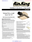
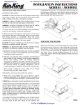
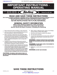
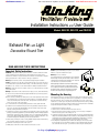
::bathroomsource.com
Call 1-800-667-8721 anywhere in the US and Canada -
www.bathroomsource.com
Installation Instructions and User Guide
Models DRLC702, DRLC703, and DRLC709
Exhaust Fan with Light
Decorative Round Trim
READ AND SAVE THESE INSTRUCTIONS
Important Safety Instructions
Caution: For general ventilating use only. Do not use to exhaust
hazardous or explosive materials and vapors.
CAUTION: The equipment covered by these instructions should be installed and serviced
only by competent personnel utilizing proper safety practices and procedures. These
instructions are written for such personnel and are not intended as a substitute for adequate
training and experience in safe procedures for this type of equipment.
Warning: Do not use in kitchens.
To ensure the best air and sound performance, it is recommended
that the length of ducting and the number of elbows be kept to
a minimum, and that insulated hard ducting be used. Larger duct
sizes will reduce noise and airflow restriction.
Warning: Disconnect the power at service panel before beginning this installation.
Caution: To reduce the risk of fire and to properly exhaust air, be sure to duct air outside. Do
not vent exhaust air into spaces within walls or ceilings, or into attics, crawl spaces, or garages.
Before beginning this installation remove the fan's venturiassembly,
which is secured in place with one screw through the venturi.
This is a captive screw and will stay installed in the venturi. Keep
the venturi assembly and grill/lens/light reflector assembly in
the carton until needed so they do not get damaged or lost.
Acceptable for use over tub or shower when installed in a GFCI protected branch circuit.
Warning: To reduce the risk of fire or electric shock, do not use this fan with any solid-state
speed control device.
Warning: To reduce the risk of fire or electric shock or injury to persons, observe the following:
a) Use this unit only in the manner intended by the manufacturer. If you have any questions,
please contact the manufacturer.
b) Before servicing or cleaning unit, switch power to off at service panel and lock the service
disconnecting means to prevent power from being switched on accidentally. When the
service disconnecting means cannot be locked, securely fasten a prominent warning
device, such as a tag, to the service panel.
c) Do not install this fan in a ceiling thermally insulated to a value greater than R-40
d) Installation work and electrical wiring must be done by qualified, competent, trained
person(s) in accordance with all applicable codes and standards using proper safety
practices, including fire-related construction.
e) Sufficient air is needed for proper combustion and exhausting of gases through the flue
(chimney) of fuel burning equipment to prevent back drafting. Follow the heating equipment
manufacturer’s guideline and safety standards such as those published by the National
Fire Protection Agency (NFPA) and the American Society for Heating, Refrigeration, and
Air Conditioning Engineers (ASHRAE), and the local code authorities.
f) When cutting or drilling into a wall or ceiling, ALWAYS identify hidden electrical wiring
and other hidden utilities in advance, to avoid damage.
g) Ducted fans must always be vented to the outdoors.
f) NEVER place a switch where it can be reached from the tub or shower.
Mounting the Housing
Fig. 2
Select the best location to mount the housing in the ceiling. This fan will require at least
6" of clearance in the ceiling, and will mount through drywall up to 3/4" thick. The fan can
be mounted directly to the joist using the two mounting tabs on the sides of the housing
or between 16" on center joists using the 4 provided mounting rails. Before cutting or drilling
into any drywall, check the area from above to plan the unit's wiring and duct run. Remember
to keep the duct length and number of elbows to a minimum.
1. Determine the best location for the fan.
2. Select the most convenient electrical knockout and remove it.
3. If the unit is being mounted in existing construction, use the housing as a template to
mark the necessary space on the ceiling to cut out.
4. Locate the housing next to the joist and adjust the height so the housing is level with the finished
ceiling. If the unit is being installed in new construction, use the drywall thickness gauge to line
up the bottom of the joist with the appropriate drywall thickness indicated (fig. 1). Secure the
housing directly to the joist through the two holes and two keyhole slots provided.
5. If mounting the housing between joists install the side rails (fig. 2) on the housing. Position
the housing next to the joist and adjust the height so it is flush with the drywall. Secure the
ends of the slide rails to the joists – you can then move the housing into the final position.
Air King at bathroom::accessories
U
Fig. 1
N
L
I
M
I
T
E
D
::bathroomsource.com
Call 1-800-667-8721 anywhere in the US and Canada -
www.bathroomsource.com
the electrical wires to the housing with an approved electrical connector. Make sure you
leave enough wiring in the box to make the connection to the fan and light receptacle.
2. From where you have access to inside the fan's junction box, connect the white wire from
the house to both the fan's white wire and the light's white wire. Connect one black wire
from the double switch to the fan's black wire and the other black wire from the double
switch to the light's black wire. If you are using a single switch to control both fan and
light, connect both fan and light's white wire to the house white wire, and both fan and
light's black wire to the switch black wire. Connect the ground wire from the house to the
fan's green ground. Use approved electrical wire nuts.
Ducting
Note: All ducting must comply with local and national
building codes.
1. Connect the ducting to the fan's duct collar. Secure in
place using duct tape or screw clamp. Always duct the
fan to the outside through a wall or roof cap. To ensure
maximum air delivery, keep the length of duct and number
of elbows to a minimum.
Electrical Wiring
Completing the Installation
WARNING: POWER MUST BE PROVEN DISCONNECTED
BEFORE STARTING INSTALLATION, INSPECTION OR
MAINTENANCE! FAILURE TO DO SO MAY CAUSE SERIOUS
INJURY, DEATH AND/OR PROPERTY DAMAGE.
Caution: Make sure power is switched off at service panel
Fig. 3
before beginning this installation.
Note: All wiring must comply with local and national codes.
You must ground this unit.
Note: The unit can be controlled with a standard single wall switch for on/off control of
both fan and light, or a standard double wall switch for independent on/off control
of the fan and light.
1. Run wiring from an approved wall switch carrying the appropriate rating. One neutral (white),
one ground (green or bare copper), and two hot (black leads connected to the switch). Secure
1. To complete the installation, reinstall the fan’s venturi assembly. With the venturi at
approximately a 45 degree angle, hook the two tabs on the venture into the slots on the
housing and secure in place by tightening down the venturi screw. Rotate the blower wheel
by hand to ensure it revolves freely. Now plug the fan motor into the appropriate receptacle.
2. To install the grill/lens/light reflector assembly, first remove the glass lens from the grill
base by loosening the top nut. The glass lens will then lift off the center rod. (fig 3.)
3. Using the two #8 screws (packaged with the grill & Lens ) secure the grill base to the
housing by installing the screws through the 2 holes in the grill base and into the lances
on the side of the housing. (fig 3). Remember to plug the lamp holder into the appropriate
receptacle before securing the grill base in place.
4. Once the grill base is secure install the bulbs (2 x 60 watt max) and reinstall the glass lens,
securing in place using the spacer and top nut. (fig 3)
5. Turn the power back on and test your installation.
Troubleshooting Guide
Trouble
Probable Cause
Suggested Remedy
1. Fan does not operate when the switch is on.
1a. A fuse may be blown or a circuit tripped.
1b. Connector plug from motor is not plugged in.
1a. Replace fuse or reset circuit breaker.
1b. Turn off power to unit. Remove Grill and plug
motor into receptacle in housing. Restore power
to unit.
2. Fan is operating, but air moves slower than normal.
2.
2.
3. Fan is operating, is louder than normal.
3a. Motor is loose.
Obstruction in the exhaust ducting.
3a. Turn off power to unit. Remove grill and check
that all screws are fully tightened. Restore
power to unit.
3b. Call your dealer for service.
3b. Fan blade is hitting housing of unit.
Air King at bathroom::accessories
U
N
L
I
M
I
Check for any obstructions in the ducting. The
most common are bird nests in the roof cap or
wall cap where the fan exhausts to the outside.
T
E
D