1
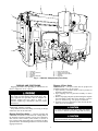
16DF013-050
Hermetic Absorption Liquid
Chiller/Heaters
Installation Instructions
SAFETY CONSIDERATIONS
Absorption liquid chiller/heaters provide safe and reliable
service when operated within design specifications. When
operating this equipment, use good judgment and safety precautions to avoid damage to equipment and property or injury to personnel.
Be sure you understand and follow the procedures and safety
precautions contained in the machine instructions as well as
those listed in this guide.
DO NOT USE OXYGEN or air to purge lines, leak test, or
pressurize a machine. Use nitrogen.
NEVER EXCEED specified test pressures. For the 16DF machine, the maximum pressure is 12 psig (83 kPa). For the
chilled/hot water and condensing water piping, the maximum pressure is stamped on the machine.
WEAR goggles and suitable protective clothing when handling lithium bromide, octyl alcohol, inhibitor, lithium hydroxide, and hydrobromic acid. IMMEDIATELY wash any
spills from the skin with soap and water. IMMEDIATELY
FLUSH EYES with water and consult a physician.
DO NOT USE eyebolts or eyebolt holes to rig maching sections or the entire assembly.
DO NOT work on high-voltage equipment unless you are a
qualified electrician.
DO NOT WORK ON electrical components, including control panels or switches, until you are sure ALL POWER IS
OFF and no residual voltage can leak from capacitors or solidstate components.
LOCK OPEN AND TAG electrical circuits during servicing. IF WORK IS INTERRUPTED, confirm that all circuits
are deenergized before resuming work.
NEVER DISCONNECT safety devices or bypass electric interlocks and operate the machine. Also, never operate the
machine when any safety devices are not adjusted and functioning normally.
DO NOT REPEAT unsuccessful ignition attempts or restart
after flame failure without assurance that post-purge and prepurge have eliminated combustible gas or oil vapors from
the combustion chamber. DO NOT EVER ATTEMPT IGNITION of a burner if there is shutdown leakage of gas or
oil through the fuel shutoff valves or from the fuel lines.
DO NOT syphon lithium bromide or any other chemical by
mouth.
BE SURE all hydrogen has been exhausted before cutting
into pure chambers. Hydrogen mixed with air can explode
when ignited.
WHEN FLAMECUTTING OR WELDING on an absorption machine, some noxious fumes may be produced. Ventilate the area thoroughly to avoid breathing concentrated fumes.
DO NOT perform any welding or flamecutting to a machine
while it is under a vacuum or pressurized condition.
NEVER APPLY an open flame or live steam to a refrigerant
cylinder. Dangerous overpressure can result. When necesary
to heat a cylinder, use only warm (110 F [43 C]) water.
DO NOT REUSE disposable (nonreturnable) cylinders or attempt to refill them. It is DANGEROUS AND ILLEGAL.
When cylinder is emptied, bleed off remaining gas pressure,
loosen the collar and unscrew and discard the valve stem.
DO NOT INCINERATE.
DO NOT ATTEMPT TO REMOVE fittings, covers, etc., while
machine is under pressure or while machine is running. DO
NOT OPERATE or pressurize a machine without all cover
plates or bolts in place.
DO NOT climb over a machine. Use platform, catwalk, or
staging. Follow safe practices when using ladders.
DO NOT STEP ON machine piping. It might break or bend
and cause personal injury.
USE MECHANICAL EQUIPMENT (crane, hoist, etc.) to
lift or move inspection covers or other heavy components.
Even if components are light, use such equipment when there
is a risk of slipping or losing your balance.
VALVE OFF AND TAG steam, water, or brine lines before
opening them.
DO NOT LOOSEN water box cover bolt until the water box
has been completely drained.
DO NOT VENT OR DRAIN water boxes containing industrial brines, liquid, gases, or semisolids without permission
of your process control group.
BE AWARE that certain automatic start arrangements can
engage starters. Open the disconnects ahead of the starters
in addition to shutting off the machine or pump.
INVESTIGATE THE CAUSE of flame failure or any other
safety shutdown before attempting a restart.
KEEP EYES sufficiently away from sight tubes or burner
openings, and wear a protective shield or safety glasses when
viewing a burner flame.
USE only repaired or replacement parts that meet the code
requirements of the original equipment.
DO NOT ALLOW UNAUTHORIZED PERSONS to tamper
with burner equipment or machine safeties, or to make major repairs.
PERIODICALLY INSPECT all valves, fittings, piping, and
relief devices for corrosion, rust, leaks, or damage.
PROVIDE A DRAIN connection in the vent line near each
pressure relief device to prevent a build-up of condensate or
rain water.
IMMEDIATELY wipe or flush the floor if lithium bromide
or octyl alcohol is spilled on it.
BE SURE combustion air inlets to the equipment room are
open and clear of any blockage.
Manufacturer reserves the right to discontinue, or change at any time, specifications or designs without notice and without incurring obligations.
Book 2
PC 211
Catalog No. 531-602
Printed in U.S.A.
Form 16DF-1SI
Pg 1
3-92
Replaces: New
Tab 5b
CONTENTS
RECEIVING THE MACHINE AND BURNER
Page
SAFETY CONSIDERATIONS . . . . . . . . . . . . . . . . 1
INTRODUCTION . . . . . . . . . . . . . . . . . . . . . . . . . . 2
General . . . . . . . . . . . . . . . . . . . . . . . . . . . . . . . . . . 2
Job Data . . . . . . . . . . . . . . . . . . . . . . . . . . . . . . . . . . 2
RECEIVING THE MACHINE AND BURNER . . 2
Identify Machine and Burner . . . . . . . . . . . . . . 2
Inspect Shipment . . . . . . . . . . . . . . . . . . . . . . . . . . 2
Check Shipping Vacuum . . . . . . . . . . . . . . . . . . 2
Check Shipping Pressure . . . . . . . . . . . . . . . . . . 2
Provide Machine Protection . . . . . . . . . . . . . . . . 2
RIGGING AND POSITIONING . . . . . . . . . . . . . . 3-6
Rigging One-Piece Units . . . . . . . . . . . . . . . . . . 3
Rigging 2-Piece Units . . . . . . . . . . . . . . . . . . . . . . 3
• PREPARATION
• RIGGING
Position and Level The Equipment . . . . . . . . 6
MACHINE ASSEMBLY . . . . . . . . . . . . . . . . . . . . 7,8
Assemble 2-Piece Units . . . . . . . . . . . . . . . . . . . . 7
Machine Leak Test . . . . . . . . . . . . . . . . . . . . . . . . 7
Machine Evacuation . . . . . . . . . . . . . . . . . . . . . . 7
MOUNTING THE BURNER . . . . . . . . . . . . . . . . 8,9
Rigging . . . . . . . . . . . . . . . . . . . . . . . . . . . . . . . . . . 8
Frontplate an Burner Installation . . . . . . . . . . 8
Fuel System Installation . . . . . . . . . . . . . . . . . . 9
• GAS TRAIN
• OIL SUPPLY SYSTEM
FIELD PIPING . . . . . . . . . . . . . . . . . . . . . . . . . . . . 9-12
Connect Water Piping . . . . . . . . . . . . . . . . . . . . . . 9
Fusible Plug Drain Piping . . . . . . . . . . . . . . . . . . 11
Connect Rupture Disc Piping . . . . . . . . . . . . . . 12
Connect Fuel Piping . . . . . . . . . . . . . . . . . . . . . . 12
Connect Exhaust Duct . . . . . . . . . . . . . . . . . . . . 12
INSULATION AND PAINT . . . . . . . . . . . . . . . . . . 12
Insulation (If Required) . . . . . . . . . . . . . . . . . . . . 12
Final Paint Coat (If Required) . . . . . . . . . . . . . . 12
ELECTRICAL CONNECTIONS . . . . . . . . . . . . . . 12
Check Available Power Supply and Safety
Interlocks . . . . . . . . . . . . . . . . . . . . . . . . . . . . . . . . 12
Machine Control Panel External Wiring . . . . 12
Burner Control Panel Wiring . . . . . . . . . . . . . . 12
INITIAL SOLUTION AND REFRIGERANT
CHARGING . . . . . . . . . . . . . . . . . . . . . . . . . . . . . . 12
NOTE: The chiller/heater machine and the burner are shipped
separately from different sources.
Identify Machine and Burner — The machine and
burner model numbers and serial numbers are stamped on
machine identification plates. Check this information against
shipping papers and job data.
Inspect Shipment — (Fig. 1). Single-piece machines
are at a deep vacuum when shipped. Do not open any valves
until the vacuum has been noted. Refer to Check Shipping
Vacuum section, below. Machines shipped in 2 pieces are
under nitrogen pressure.
Inspect for shipping damage while machine and burner
are still on shipping conveyance. If either appears to be damaged or has been torn loose from its anchorage, have it examined by transportation inspectors before removal. Forward
claim papers directly to transportation company. Manufacturer is not responsible for any damage incurred in transit.
Check all items against shipping list. Immediately notify
your Carrier office if any item is missing.
To prevent loss or damage, leave all parts in original packages until installation.
Check Shipping Vacuum — To check for leaks that
have occurred during shipment on single-piece machines:
1. Connect an absolute pressure gage to a service valve.
2. Record the absolute pressure of the assembly. If vessel
pressure is greater than 0.28 in. (7 mm) of mercury, the
machine has acquired a leak in shipping, and must be leak
tested. Refer to the Machine Leak Test procedure for instructions.
Check Shipping Pressure — To check for leaks that
have occurred during shipment on 2-piece machines:
1. Connect a pressure gage (30 psig [200 k Pa]) to a service
valve on each piece.
2. If the vessel has lost its pressure, it has acquired a leak
during shipping and must be leak tested after positioning
and assembly. Refer to the Machine Leak Test section for
instructions.
Provide Machine Protection — If the machine will
not be installed immediately, it is very important to use a
drop cloth or plastic covering to protect the machine from
construction dirt and moisture before installation. Also, do
not remove protective shipping cover on control panel until
ready to use.
INTRODUCTION
General — The 16DF machine is factory assembled, wired,
and leak tested. Installation (not by Carrier) consists primarily of establishing water, fuel, exhaust, and electrical services to the machine as well as mounting and connecting the
burner. Rigging, installation, insulation, painting, field wiring, and field piping are the responsibility of the contractor
and/or customer. Carrier has no installation responsibilities
for the equipment.
Job Data — Necessary information consists of: machine location drawings, piping drawings, field wiring diagrams, and rigging guide.
2
2
3
4
1
11
10
9
1
2
3
4
5
6
—
—
—
—
—
—
8
7
6
7
8
9
10
11
Condenser
Low-Stage Generator
Flue Stack
Separator
High-Stage Generator
Burner
—
—
—
—
—
5
Burner Control Panel
Solution Heat Exchanger
Chiller/Heater Control Panel
Absorber
Evaporator
Fig. 1 — Machine Components (Front View)
RIGGING AND POSITIONING
Rigging 2-Piece Units
Lifting machine from points other than those specified
may result in serious damage and personal injury. Rigging equipment and procedure must be adequate for
machine weights and sizes. Refer to Table 1 for
machine weights, Fig. 2 and Tables 2 and 3 for overall
dimensions.
PREPARATION — Two-piece units must be prepared for
installation before they can be rigged.
1. Open auxiliary evacuation valves to relieve pressure in
absorber-evaporator shell.
2. Open shipping valve on generator assembly to relieve
pressure.
3. Remove all piping end plates by flamecutting the end plate
and weld flange around their outer diameter. Cut these
pieces as shown in Fig. 5 for proper reconnection.
4. Grind the cut pieces smooth for a close fit when the machine pieces are assembled.
Carefully position cables on machine to avoid damage to
small piping, controls, or wiring.
Keep shell horizontal when lifting or lowering so all legs
contact the floor at the same time.
To avoid contaminates and debris getting into chiller,
do not leave machine open any longer than necessary.
Rigging procedures vary depending on whether the machine is shipped in one or 2 pieces.
Rigging One-Piece Units — Lift entire assembly with
cable hooks and shackles connected to the 3 lifting holes on
the absorber-evaporator assembly (lower part of machine),
and with the center balance point location, as shown in
Fig. 3 and 4. Lifting from other holes or locations can damage the machine. See Mounting the Burner section for burner
rigging instructions.
Do not remove any stock from pipe ends. Do not get
slag inside machine while flamecu<tting.
3
Fig. 2 — 16DF Views (Typical)
V — Lifting Holes
Fig. 3 — Rigging One-Piece Units, Typical, Top View
4
Fig. 4 — Rigging One-Piece Units, Typical, Side and End Views
Table 1 — Rigging Weights
English
SHIPPING WEIGHT (lb)
AbsorberHighUNIT
Evaporator
Temperature
16DF Low-Temperature GeneratorGenerator
Separator
Assembly
Assembly
013*
—
—
015*
—
—
018*
—
—
020*
—
—
023
14,560
3,970
025
14,780
3,970
028
16,100
8,600
032
16,540
8,600
036
18,530
8,820
040
18,970
8,820
045
21,610
10,150
050
22,050
10,150
SI
SHIPPING WEIGHT (kg)
AbsorberHighUNIT
Evaporator
Temperature
16DF Low-Temperature Generator
Generator
Separator
Assembly
Assembly
013*
—
—
015*
—
—
018*
—
—
020*
—
—
023
6 600
1800
025
6 700
1800
028
7 300
3900
032
7 500
3900
036
8 400
4000
040
8 600
4000
045
9 800
4600
050
10 000
4600
*16 DF013-020 are shipped in one section
Fig. 5 — Flamecutting and Welding Detail
5
Total
Weight
OPERATING
WEIGHT
(lb)
13,230
13,450
15,220
15,440
18,530
18,750
24,700
25,140
27,350
27,790
31,760
32,200
17,200
17,420
20,290
20,510
24,920
25,140
32,640
33,080
37,050
37,490
43,660
44,100
Total
Weight
OPERATING
WEIGHT
(kg)
6 000
7 800
6 100
7 900
6 900
9 200
7 000
9 300
8 400
11 300
8 500
11 400
11 200
14 800
11 400
15 000
12 400
16 800
12 600
17 000
14 400
19 800
14 600
20 000
as standard.
Table 2 — Overall Dimensions, 16DF013-025
English
UNIT
16DF
LENGTH
WIDTH
HEIGHT
UNIT
16DF
LENGTH
WIDTH
HEIGHT
013
11-10
6- 7
7- 9
013
3600
1995
2350
OVERALL DIMENSIONS (ft-in.)
015
018
020
023
11-10
11-10
11-10
11-10
6- 7
7- 8
7- 8
8- 3
7- 9
7- 9
7- 9
8- 3
SI
OVERALL DIMENSIONS (mm)
015
018
020
023
3600
3600
3600
3600
1995
2330
2330
2520
2350
2350
2350
2500
025
11-10
8- 3
8- 3
025
3600
2520
2500
Table 3 — Overall Dimensions, 16DF028-050
English
UNIT
16DF
LENGTH
WIDTH
HEIGHT
UNIT
16DF
LENGTH
WIDTH
HEIGHT
028
15-4
9-4
8-6
028
4660
2850
2595
OVERALL DIMENSIONS (ft-in.)
032
036
040
045
15-4
15- 4
15- 4
15-4
9-4
9-10
9-10
10-6
8-6
8-10
8-10
9-8
SI
OVERALL DIMENSIONS (mm)
032
036
040
045
4660
4660
4660
4660
2850
3000
3000
3200
2595
2695
2695
2950
Absorber-Evaporator Low-Temperature Generator Assembly
050
15-4
10-6
9-8
050
4660
3200
2950
RIGGING — The 2 pieces are the high-temperature generatorseparator assembly and absorber-evaporator low-temperature
generator assembly (Fig. 6).
1. Lift each assembly with cable, hooks, and shackles connected to the 4 lifting holes on each assembly. Lifting
from other holes or locations can damage the machine.
2. Position and level the absorber-evaporator-assembly first.
See Position and Level the Equipment section.
3. Move the generator-separator assembly into place beside
the absorber-evaporator assembly.
4. Align connecting piping for generator-separator and absorberevaporator assemblies. Make sure serial numbers correspond on both assemblies.
5. See Mounting the Burner section for burner rigging
instructions.
High-Temperature Generator-Separator Assembly
Fig. 6 — Rigging 2-Piece Units, Sizes 16DF023-050
Position and Level the Equipment — Isolation
pads are not necessary for most installations. However, for
cases where isolation pads are required, refer to Fig. 7 for
typical installation.
Both 16DF machine assemblies must be level within
1⁄4 in. per 20 ft (6.3 mm per 6 m), both lengthwise and diagonally. To level the machine, proceed as follows:
1. Completely fill 50-ft (15 m) length of clear flexible tubing with water.
2. Use water gage and leveling reference points stamped on
tube sheets to level machine.
3. Level machine with shims until requirements are met. If
isolation assembly is used, shim under the soleplate. Be
sure matching piping is in alignment.
NOTES:
1. Be sure only the machine base is on the isolation pad at each
corner.
2. Shim under soleplate to level machine.
Fig. 7 — Typical Isolation Assembly
6
MACHINE ASSEMBLY
Machine Leak Test — All field-welded joints on the
chiller must be leak tested prior to starting the machine. Leak
test as follows:
1. Close all external service valves.
2. If machine is under vacuum, bring to atmospheric pressure with dry air or dry nitrogen.
3. Pressurize to 6 psig (40 kPa) with tracer gas. Charge through
auxiliary evacuation valve.
4. Increase the machine pressure to 12 psig (80 kPa) with
dry air or dry nitrogen.
No assembly is required for one-piece units (16DF013020) other than installing the burner. See Mounting the Burner
section.
Assemble 2-Piece Units (Fig. 8 and 9)
1. Weld piping connections and make sure weld connections are vacuum leak tight.
2. Install the burner. See Mounting the Burner section.
Exceeding 12 psi (80 kPa) can cause severe damage
to chiller.
5. Leak test all field-welded joints with electronic leak detectors or equivalent. If machine has acquired a leak in
shipment or rigging, all joints must be leak tested.
6. After leak testing has been completed and leaks have been
corrected, release the machine pressure.
Machine Evacuation — Removal of non-condensables
from the machine is required after machine has been opened.
To evacuate the machine, proceed as follows:
1. Connect auxiliary evacuation device (Fig. 10) to auxiliary evacuation valve. Be sure that the line is as short as
possible and that line size is not smaller than connection
to auxiliary device. A check valve or oil trap must be used
on the suction lines to keep vacuum pump oil out of the
chiller. Be sure that all connections are vacuum tight.
2. Close external service valve(s).
3. Start auxiliary evacuation device. Open auxiliary evacuation valve. Reduce machine pressure to one in. of mercury absolute or lower. Check pressure with absolute pressure
gage at refrigerant pump service valve.
Fig. 8 — Machine Piping Assembly
Diagram, End View
Fig. 9 — Machine Piping Assembly Diagram, Side View
7
4. Close auxiliary evacuation valve and shut off auxiliary
evacuation device.
5. Note and record absolute pressure gage reading.
6. Coat all machine field-welded joints with weld sealant.
Frontplate and Burner Installation To prevent leakage of high-temperature combustion gases with this type of
forced draft burner, a high-temperature insulating gasket or
1/2-in. Fiberfrax® rope seal is required between the generator and the front plate assembly, and between the front plate
and the burner assembly.
Either the gasket or the rope may be provided with the
burner, depending on manufacturer’s availability.
When using high-temperature insulating rope, it must
be wrapped around the flange circumference INSIDE of
the mounting studs or bolt holes, with overlapping ends,
to provide a complete gas tight seal. Wrapping the rope
around the outside of the studs or bolt holes could allow
high-temperature gas leakage through the holes in the
attached plates.Use either gasket cement or masking tape
to hold the ropes in place during installation of the front
plate and burner assemblies.
Fig. 10 — Auxiliary Evacuation Device
MOUNTING THE BURNER
The burner is shipped and installed as 3 separate subassemblies (Fig. 11):
• front plate and refractory assembly, which is attached to
the generator
• burner assembly, which is attached to the frontplate
• gas train and/or oil supply system, which are connected to
the burner
1. Place the high-temperature gasket or insulating rope on
the generator mounting flange, inside the bolt holes.
2. Position the frontplate and refractory assembly against the
generator mounting flange, with the refractory can extending into the generator fire tube. Secure in place with
washers, nuts, and bolts.
3. Place the high-temperature gasket or insulating rope on
the frontplate flange, inside the studs.
4. Position the burner assembly with the burner head extending into the front plate and refractory assembly, making sure it is plumb. Secure in place with the retaining
lugs on the frontplate studs to ensure a rigid mounting.
Keep the control panel door closed during the burner installation to avoid damage. Also, it is good practice to
remove the flame safeguard chassis during installation and
to store it in a safe, dry place until start-up.
5. Measure and fabricate burner support pedestal from pipe(s)
with pipe thread on both ends. Screw the support pipe
into the support receptacle, and then screw the opposite
end into the collar that is welded to the underside of the
burner housing. Adjust or shim until the burner is level
and firmly supported.
Rigging — Rigging should be used to position both the
front plate assembly and the burner assembly because of their
weights. Refer to the shipping container or paperwork for
the weight of these units. For the front plate, either webbed
strapping placed around the refractory can or a lifting bar in
the center opening may be used.
IMPORTANT: Be careful that the assembly does not
slip off.
For burner assemblies which do not have lifting lugs, place
webbed strapping around a central balance area of the burner.
IMPORTANT: Be careful to avoid damage to small
piping, controls, or wiring.
Fig. 11 — Burner Mounting
8
Fuel System Installation — See Fig. 12-14 for typical gas train and oil supply system arrangements. Refer to
burner manual supplied with the burner for installation instructions on the particular version of gas train and/or oil
supply system used with your application. These systems are
supplied pre-assembled, and with pre-installed interconnection fittings.
IMPORTANT: Do not use copper tubing for the gas
pilot supply.
Gas supply and vent connections are discussed under Connect Fuel Piping in the Field Piping section of this manual.
OIL SUPPLY SYSTEM — This burner uses a separate motordriven oil pump which should be located close to the burner
and secured to the floor. The oil pump connections are identified with tags for suction (supply) and return lines. The piping diagram with mounting dimensions and port sizes for
your particular application is shown in the burner manual.
Oil supply and return connections are discussed under Connect Fuel Piping in the Field Piping section of this
manual.
Do not use Teflon tape on any threaded connections as
a gas or oil pipe sealant. Loose tape pieces can cause
valve leakage and are a safety hazard. Use a pipe joint
compound.
GAS TRAIN — The high-gas pressure switch is mounted
on the gas train piping for convenience only, and does not
monitor the gas pressure at that location. A brass pipe tee
and a coil of 3/8-in. aluminum tubing with fittings are supplied to connect the sensing line between the pressure switch
and the top of the burner manifold, as shown with dashed
lines on the gas train piping schematic.
Another coil of 3/8-in. aluminum tubing with compression fittings is provided for the pilot connection between the
pilot shutoff valve (mounted ahead of the main manual shutoff valve) and the pilot gas pressure regulator (mounted on
the burner).
ITEM
1
2
3
4
5
6
7
8
9
10
11
12
13
FIELD PIPING
Connect Water Piping — Install piping using job data,
piping drawings, and procedures outlined below. A typical
piping installation is shown in Fig. 15.
1. Make sure all connections to water box covers allow opening of covers for maintenance.
2. Installation and piping should allow sufficient access for
cleaning or replacing tubes.
3. Install pipe hangers where needed. Make sure no weight
or stress is placed on water box nozzles or flanges.
DESCRIPTION
Pilot Shutoff Cock
Pilot Gas Pressure Regulator
Second Safety Shutoff
Pilot Valve (if used)
Safety Shutoff Pilot Valve
Gas Pressure Gage (if used)
Manual Leak Test Valve
Butterfly Gas Valve
High Gas Pressure Switch
Safety Shutoff Gas Valve
Second Safety Shutoff Gas Valve
Low Gas Pressure Switch
Gas Pressure Regulator
Manual Gas Shutoff Valve
NOTES:
1. Piping and fittings shown dashed to be supplied and installed by the burner
installation contractor.
2. For proper regulation and performance, regulators with internal control
require at least 5 pipe diameters of straight pipe on the outlet side uninterrupted with fittings, elbows, etc.
3. The outlet screwed connections must conform with good piping practices, free of excess thread engagement.
4. The top cap at the spring must be in place or unstable operation can
occur.
5. For parts not identified, see burner manufacturer’s material list.
Fig. 12 — Gas Train, Typical
9
NOTES:
1. Oil system schematic shown in high fire
position.
2. Supply pressure must not exceed 3 psi
(20 kPa) or pump seals may be damaged.
Fig. 13 — Mechanical Pressure Atomizing, Light Oil (Pump with External Regulating Relief Valve)
NOTES:
1. Oil system schematic shown in high fire
position.
2. Supply pressure must not exceed 3 psi
(20 kPa) or pump seals may be damaged.
Fig. 14 — Mechanical Pressure Atomizing, Light Oil (Pump with Integral Regulating Relief Valve)
10
2. Do not loosen or disconnect fusible plug while connecting relief pipe to it.
3. Make sure connections to fusible plug are threaded and
allow easy piping removal for leak test and maintenance.
4. Install pipe hangers where needed to be sure no weight or
stress is placed on the fusible plug.
4. Water flow direction must be as specified in job flow diagrams or water flow markings on water boxes, and connections must be to the correct entering and leaving water box nozzles.
5. Install water box vent and drain piping in accordance with
individual job data. Air vents should be at all high points
in piping to eliminate water hammer.
6. Location of the chilled hot water and cooling water pumps
as well as the expansion tank must allow for the hydrostatic and water heads, to ensure that the total pressure
does not exceed the water box design working pressure.
7. A cooling tower bypass valve should be installed if the
cooling water temperature might fall below 59 F (15 C)
during chiller operation.
8. Install thermometer wells and thermometers on the entering and leaving chilled/hot water pipes, absorber entering and leaving cooling water pipes, and condenser leaving
cooling water pipe. Thermometer wells should extend into
the pipe a minimum of 1⁄3 pipe diameter.
9. Install pressure gage taps and pressure gages on the entering and leaving chilled/hot water pipes and cooling water pipes.
Fusible Plug Drain Piping (Fig. 16)
1. Connect drain piping to discharge hot water to safe area.
Fig. 16 — Fusible Plug Drain Piping
LEGEND
— PRESSURE GAGE
— STRAINER
— THERMOMETER
— CHECK VALVE
— FLOW METER
— MACHINE ENVELOPE
Fig. 15 — Piping Flow Schematic
11
Connect Rupture Disc Piping — Vent rupture disc
to the outside of the building for safety. Model 16DF machines sometimes are factory equipped with a rupture disc
assembly on the generator-vapor transfer area.
1. Add a flexible connection and adequate support to pipe,
as required, to eliminate any piping stress on rupture disc.
Provide fittings so vent piping can be disconnected periodically for inspection of disc. Provide pipe plug on outlet side of relief device for leak testing.
2. Cover outdoor vent with a rain cap to prevent excessive
moisture from entering the vent line.
3. Place a condensate drain at the low point in the piping to
prevent any water build-up on the atmospheric side of
the disc assembly.
Connect Fuel Piping — Connect fuel lines to burner
fuel system and install separate fuel fittings using job data,
piping drawings, and general guidelines found in the burner
manual supplied by the burner manufacturer. Installation requirements will vary for local building and insurance codes,
and for different application conditions.
Do not use Teflon Tape as an oil or gas pipe sealant.
Tape can cause valves to fail, creating a safety hazard.
Use a pipe joint compound.
1. Use a full size dirt pocket or trap in gas piping ahead of
the main manual shutoff.
2. Piping must be sized to provide the minimum specified
oil or gas pressure at the main manual shutoff when operating at the maximum input.
3. A 2-pipe system with suction and return lines must be
used for oil burners, and the lines should be run in a trench
or under the floor when possible. Copper tubing with flare
fittings should be used for oil lines.
4. Hand valves must not be installed on discharge side of oil
pump or return line without a bypass relief installed to
the tank. An oil shut-off valve should be provided in the
suction line near the burner.
5. Oil suction lines should be pitched back slightly to the
tank and care should be taken to avoid any air traps in the
line.
6. The fuel system must be pressure tested with air or inert
gas and proven leak tight. Gas systems should be tested
for at least 3 times the gas pressure that will be used.
Connect Exhaust Duct — Connect combustion exhaust ducting using job data and piping drawings. Systems
will vary for different application conditions.
1. Sharp bends and restrictions should be avoided to allow
smooth gas flow.
2. The outlet should be arranged to prevent rainwater entry
into the machine exhaust, and drains should be provided
to remove condensate or water.
3. Exhaust gas dampers and draft regulators must be installed correctly for proper operation.
Most of the machine surfaces become hot during the heating cycle and those areas should be insulated with heatresistant material. High-temperature, fire resistant material
should be used in areas near the burner, refractory door, and
exhaust. All wiring should be external to the finished insulation. The insulation should be applied so all flanged service connections can be easily opened, and all valves, controls, and sensor locations should be easily accessible.
Final Paint Coat (If Required) — Paint machine as
indicated in job data, after installation assembly, leak testing, and insulation have been completed. Use specified paint,
making sure only high-temperature paint is applied to areas
with hot surfaces.
ELECTRICAL CONNECTIONS
Field wiring must be installed in accordance with job and
machine/burner wiring diagrams, and all applicable electrical codes.
Check Available Power Supply and SafetyInterlocks — Available power supply and safety interlocks must match the machine equipment. Job voltage, amperage, and values are stated on the machine and burner wiring
diagrams.
Machine Control Panel External Wiring — All
machine sensors and controls are factory installed. External
field wiring connections to machine control panel wiring terminals include:
• three-phase power supply
• control start/stop interlocks for chilled/hot water pump(s),
cooling water pump(s), and cooling tower fan(s)
• high-temperature generator sensors on machines shipped
in 2 pieces
• remote start/stop (when used)
• remote status indicators (when used)
Burner Control Panel Wiring — Field wiring connections between wiring terminals in the machine and burner
control panels include:
• three-phase blower motor and oil pump motor power supply
• burner control power supply and burner start/stop signal
• open/close signals for firing rate positioning motor
• burner alarm and firing rate limit position signals for machine/
burner vs chiller heater microprocessor controls
There are also field wiring connections between the highstage generator’s low-level probe and its relay contacts in
the burner control panel, and between the burner control panel
and the fuel line connector box.
INITIAL SOLUTION AND REFRIGERANT
CHARGING
Lithium bromide solution and refrigerant (water) will be
placed in the machine at initial start-up. Do not charge solution into the machine until the unit is ready for operation.
INSULATION AND PAINT
Insulation (If Required) — Apply insulation as indicated in job data, after machine assembly and field piping
have been completed. If shipping vacuum or pressure test
indicate possible leakage, do not apply insulation until leak
has been corrected.
Do not start any pump motors until the machine has been
charged with solution and refrigerant. The hermetic pumps
can be seriously damaged by dry operations.
Refer to 16DF Start-up, Operation, and Maintenance Instructions for charging procedures.
Copyright 1992 Carrier Corporation
Manufacturer reserves the right to discontinue, or change at any time, specifications or designs without notice and without incurring obligations.
Book 2
PC 211
Catalog No. 531-602
Printed in U.S.A.
Form 16DF-1SI
Pg 12
3-92
Replaces: New
Tab 5b