1
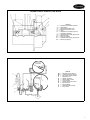
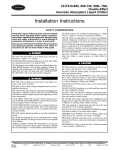
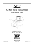
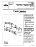
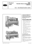
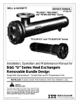
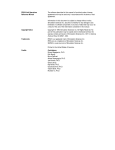
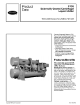
Product
Data
16JB
Steam/Hot Water
Single Effect, Hermetic Absorption
Liquid Chiller
with Product Integrated Controls (PIC)
50/60 Hz
108 to 680 Nominal Tons (380 to 2392 kW)
Carrier’s 16JB single effect hermetic
absorption liquid chiller offers a viable alternative to traditional electric
driven chillers. By utilizing low
pressure steam or hot water, the
16JB avoids high cost electricity and
qualifies for utility rebates and incentives as a gas cooling product.
The utilization of low pressure steam
or hot water in the generator provides the 16JB with application
flexibility.
• no CFCs; environmentally friendly
• one-stage design for simple, reliable operation
• operates using low pressure steam
or hot water
• quiet, vibration-free operation
• few moving parts equates to high
reliability
• Direct Digital Controls (DDC) for
optimum chiller performance.
Features/Benefits
Single effect absorption
provides efficient, economical water chilling with
minimal use of electricity.
Cost-effective cooling
Alternative-energy chiller — The
16JB offers an alternative for building
owners who want to avoid the high
operating costs associated with electricdriven chillers. Powered by low pressure steam or hot water, the Carrier
16JB single effect absorption chiller
not only reduces or eliminates electric
demand and/or ratchet charges, but
also allows the owner to take advantage of gas cooling rebates and
incentive programs offered by many
utility companies.
Copyright 1998 Carrier Corporation
Form 16JB-2PD
Single, reliable operation — The
16JB absorption chiller employs a
single generator to provide one stage
of solution reconcentration, making
it the most basic of the cycles available
today. Simplicity of design, combined
with its numerous other quality features, equates to inherently high reliability. Few moving parts and simple,
dependable operation reduce downtime, as well as service and maintenance costs. The 16JB chiller offers
typical full-load steam rates of approximately 18 lb/hr-ton at standard
ARI (Air Conditioning and Refrigeration Institute) operating
conditions.
Superior part-load performance
— The 16JB’s standard concentration
control system allows stable, partload operation at cooling water temperatures as low as 55 F (12.8 C)
without the need for a cooling tower
bypass. In addition, a control valve
ensures stable, continuous evaporator
pump operation at part-load conditions. The 16JB has a continuous
operating range from 100% to10% of
machine capacity.
Application versatility
Designed to suit a variety of applications — The use of steam or hot
water from a number of sources allows
the 16JB machine to meet a variety
of cooling needs. Waste heat sources
generated from industrial processes
and cogeneration systems can be utilized to provide chilled water for
process cooling as well as comfort
cooling, reducing the need for
purchased energy and contributing to
even greater energy savings.
Ideal for new or retrofit applications — Whether intended for replacement of existing chiller systems
or for new construction purposes, the
16JB is well suited to meet the needs
of almost any cooling application. The
16JB’s 15 model sizes, spanning a
capacity range of 108 to 680 tons,
make the 16JB single effect absorption
chiller the ideal choice for comfort
cooling and/or light industrial applications. Carrier’s computerized performance ratings assist in the selection of
the appropriate machine, properly
sized to meet exact job requirements.
Dependable operation, as well as
low sound and vibration levels, ensures occupant comfort, even when
installed on upper floors.
2
Combine absorption and
electric-driven chillers — Utilizing
both absorption and electric chillers in
a central plant offers the flexibility to
base load one chiller, while using
the other to handle peak load requirements. Hybrid chiller systems have
proven to be an economical solution
for many comfort cooling installations.
In many geographical areas, operating the electric chiller as the base
loaded machine, while utilizing the
absorption chiller during peak load
conditions, avoids or reduces electric
demand charges. Depending on utility
rate structures, a 16JB single effect
absorption chiller used in conjunction
with an electric-driven chiller may
be the most efficient and cost-effective
combination available.
Location and installation
savings
Ease of installation — All 16JB’s
are completely fabricated, assembled, and wired in the factory as single
piece units. Standard shipping configuration is either 1- or 2-piece(s),
depending on size. Refer to the 16JB
Standard Shipping Configuration
table below.
16JB STANDARD SHIPPING
CONFIGURATION
SIZE
010-047
054-068
1-PIECE
X
2-PIECES
X
Model sizes through 16JB047 ship
completely assembled as standard with
an option for 2-piece shipment. The
2-piece shipment is ideal for retrofit or replacement installations where
access into the equipment room
may be limited. The 16JB054-068
machines ship in 2 pieces as standard
for easier handling and rigging. Jobsite re-assembly and alignment of
units shipped in 2 sections is simplified by pre-erecting the machine in
the factory and incorporating
weld-type assembly flanges on all
interconnecting piping.
Table of contents
Page
Features/Benefits . . . . . . . . . . . . . . . . . . . . . . . . . . . . . . . . . . . . . . . . . . . . . . . . . 1-7
Model Number Nomenclature . . . . . . . . . . . . . . . . . . . . . . . . . . . . . . . . . . . . . . . . 2
Options and Accessories . . . . . . . . . . . . . . . . . . . . . . . . . . . . . . . . . . . . . . . . . . . . 8
Machine Components . . . . . . . . . . . . . . . . . . . . . . . . . . . . . . . . . . . . . . . . . . . . 9,10
Physical Data . . . . . . . . . . . . . . . . . . . . . . . . . . . . . . . . . . . . . . . . . . . . . . . . . . . 11,12
Dimensions . . . . . . . . . . . . . . . . . . . . . . . . . . . . . . . . . . . . . . . . . . . . . . . . . . . . . . 13
Performance Data . . . . . . . . . . . . . . . . . . . . . . . . . . . . . . . . . . . . . . . . . . . . . . . . 14
Application Data . . . . . . . . . . . . . . . . . . . . . . . . . . . . . . . . . . . . . . . . . . . . . . . . . 15,16
Electrical Data . . . . . . . . . . . . . . . . . . . . . . . . . . . . . . . . . . . . . . . . . . . . . . . . . . 17,18
Controls . . . . . . . . . . . . . . . . . . . . . . . . . . . . . . . . . . . . . . . . . . . . . . . . . . . . . . . . 19-21
Typical Piping and Wiring . . . . . . . . . . . . . . . . . . . . . . . . . . . . . . . . . . . . . . . . . . 22
Guide Specifications . . . . . . . . . . . . . . . . . . . . . . . . . . . . . . . . . . . . . . . . . . . . . 23-28
Model number nomenclature
Features/Benefits (cont)
Microprocessor control
features/benefits
Direct Digital Product Integrated
Control (PIC) — Carrier’s PIC
provides unmatched flexibility and
functionality. Each unit integrates
directly with Carrier’s Comfort Network (CCN), providing a system solution to controls applications. PICs
are pre-programmed to meet precise
control requirements.
PID (Proportional/Integral/
Derivative) control algorithms —
PID algorithms provide tight chilled
water control to optimize chiller
operation.
Local Interface Device (LID) —
The LID, which can be configured to
display in English or Metric units, provides unparalleled ease of operation.
A 16-line by 40-character backlit,
liquid crystal display (LCD) features
4 menu-specific softkeys. A default
display offers a one-glance review of
key chiller operation data, simplifying the interaction between machine
and user.
Chilled water reset — Reset can be
accomplished manually or automatically from the building management
system. Chilled water reset saves
energy when warmer chilled water
can be used.
Steam demand limit — During
start-up, the steam demand limit provides boiler protection (low feedwater, steam starvation) by limiting
control valve travel during the initial
warm-up period.
Ramp loading — Ramp loading
ensures a smooth pulldown of water
loop temperature and prevents a rapid
increase in steam consumption.
Advanced crystallization protection — Protects against crystallization
by automatically sensing impending
abnormalities in the absorption operating cycle and taking a series of
actions to either self-correct and/or
limit the chiller from approaching the
cycle crystallization line.
Absorption cycle state points —
Absorption cycle state points provide the operator with precise and
dynamic cycle operating conditions at
any time during chiller operation.
They save time by eliminating the cumbersome task of taking solution
samples and calculating state points
and assist in both chiller operation
and diagnostics.
Refrigerant low temperature override — The capacity control valve
position is inhibited to prevent
freeze-up and ensure continuous chiller
operation.
Extensive service menu — Unauthorized access to the service menu
can be password-protected. Builtin, enhanced, diagnostic capabilities
assist in troubleshooting and recommend proper corrective action for
pre-set alarms, resulting in more up
time.
Alarm history — The last 25 alarms
and/or alerts are retained in memory
with date and time stamps. Alarm
histories reduce troubleshooting time
and cost.
Additional controls features/
benefits
• Encapsulated circuit boards —
Designed and built by Carrier, encapsulated circuit boards offer superior
reliability compared to open board
designs.
• PROM (programmable read-only
memory) based modules — PROM
modules provide protection during power failures and eliminate
time-consuming reconfiguration.
They require no battery back-up.
• Modular pull-out/plug-in design —
This feature reduces field wiring
requirements and simplifies
installation.
• Low voltage (24 v) design — Low
voltage provides ultimate assurance of personal safety and control
integrity.
Reliable operation
16JB PIC control system features
automatic monitoring and precise control of chiller operation
— Each Carrier 16JB single-effect
chiller includes a pre-programmed,
factory-mounted and factory-wired
PIC panel which is functionally tested
prior to shipment. Chiller monitoring and control is automatic and continuous, and the LID on the front
panel displays chiller operational status and fault indications in English
or metric units. The PIC panel components include a Local Interface
Device (LID), processor module
(ComfortWorks™ controller), two slave
processor modules (PSIO), a fused
disconnect switch, pump contactors,
ambient-compensated 3-phase pump
overloads, multi-tap control power
transformers, terminal blocks, relays,
and all other necessary safeties and
controls for proper chiller operation.
Single point electrical connection
— Installation costs are further reduced by eliminating field wiring between machine components. All unitmounted electrical items are
factory-wired to the chiller control
center and require only a single point
electrical connection to the machine
from the building’s electrical service. A
multi-tap transformer mounted in the
chiller panel provides secondary
single-phase power for the 16JB
controls.
Low sound and vibration levels
allow location flexibility — Low
sound and vibration levels are characteristic of absorption chillers, primarily due to the fact that the only rotating
parts are the refrigerant and solution
pumps. The overall sound level of
a Carrier 16JB is typically 80 dbA.
This allows the machine to be installed
near occupied spaces or in areas
with strict sound requirements. Low
vibration levels also make it possible
to install the chiller on upper flows
without special consideration for vibration dampening systems.
Low maintenance
Standard features simplify maintenance procedures — Every 16JB
is provided with numerous standard
design features that provide for convenient and simple maintenance. Removable waterbox covers on the
evaporator, absorber, and condenser
facilitate tube and waterbox inspection
from either end. All moving parts
are easily accessible for inspection or
replacement, as required. The U-bend
tube design in the generator greatly
reduces the likelihood of expensive
and time-consuming tube bundle
replacement. Unlike ordinary tubes,
the U-bend configuration allows the
entire tube bundle to expand or
contract as a unit when subjected to
rapid temperature changes. The tube
bundle floats and adjusts freely as a
unit, decreasing tube wear due to thermal stresses and reducing tube bundle
failures. Each shell is divided by a
‘‘U-baffle’’ forming a double sump.
The U-baffle design not only forms a
thermal barrier between the sections but also allows the solution or
refrigerant to be stored temporarily on
one side of the vessel while the other
side is being serviced, consequently
reducing maintenance costs.
3
Features/Benefits (cont)
Factory-trained service organization — Carrier’s extensive service
organization offers trained and experienced service technicians in every
major city. In addition to routine maintenance and repair services,
Carrier also offers a wide array of preventative maintenance, full maintenance, and/or extended service contracts which can be custom-tailored to
fulfill any service requirements.
Leakproof hermetic pumps cut
maintenance costs — Carrier’s
proven solution and refrigerant pump/
motors are leakproof, completely
self-contained, and hermetically sealed.
The hermetic design eliminates the
need for a separate, complicated, and
possibly leakprone seal water system
and auxiliary water piping, while
providing leak tightness and longer
machine life. There are no packing glands or seals to maintain — air
cannot leak in, fluids cannot leak
out. Specially designed bearings absorb both radial and axial thrusts
to ensure correct fit at all times. There
is no possibility of external contamination since the fluid being pumped
lubricates and cools the pump and
motor assemblies. In addition, both
the rotor and stator are separated by
a stainless steel liner that protects
the windings from the fluid being
pumped. As an additional safety feature, thermal overload switches are
embedded in the stator to protect
against high winding temperature. The
pumps are field serviceable and inspection is recommended after 6
years of operation. Pump isolation
valves are not included on 16JB machines to minimize potential leak
paths into the machine. The pump
isolation valves are not required
because of the exceptionally high
reliability of the pump/motor
assemblies.
Superior corrosion protection —
Absorption chillers must be protected
from the internal corrosion that is
always present when lithium bromide
solution is in contact with internal
machine surfaces. The Carrier 16JB
absorption chiller incorporates a
highly effective corrosion inhibitor
to provide an extra margin of
4
protection against internal corrosion.
Other inhibitors may necessitate
the use of exotic tube materials in certain heat exchangers since they are
less effective and require frequent
maintenance and analysis. The superior corrosion protection of the inhibitor allows for the use of standard
copper tubes throughout the machine
(except for the generator [90/10
cupro-nickel]). This results in long machine life and dependable operation.
Rugged machine construction
— Every Carrier 16JB offers numerous standard features designed to
provide reliable, trouble-free operation. The machine is fabricated to
meet stringent manufacturing and
design requirements. Non-clogging,
corrosion-proof spray nozzles ensure
against both corrosion and possible
blockage for continuous, reliable
operation. U-bend tubes of 90/10
cupro-nickel in the generator allow
the tube bundle to expand and adjust
freely when subjected to rapid temperature changes. Allowing for this
thermal growth and expansion reduces
tube wear and helps prevent premature tube failure. The numerous standard features mean that every 16JB
single effect chiller is built to withstand
the most rigorous duty, whether it is
used for comfort cooling or light
process applications.
Automatic motorless purge extends machine life, ensures optimum efficiency and performance
— The purge system on an absorption chiller is critical to ensuring long
machine life and efficient operation. All absorption chillers operate in
a vacuum and generate hydrogen
(and other noncondensable gases) in
small quantities, whether they are
vacuum tight or properly inhibited.
These gases are present in sufficient
volume to interfere with proper
machine operation, making it imperative that they be removed to protect
against internal corrosion, lithium bromide solution crystallization, and/or
reduction of chiller capacity. The
Carrier motorless purge system protects against these potential hazards
by operating continuously during
machine operation.
How the motorless purge operates
—The absorber eductor device discharges the solution and noncondensables into the overflow line where
noncondensables are separated from
the solution. Noncondensables flow up
the overflow line and into the condenser. The solution flows through the
secondary heat exchanger and into
the sump of the absorber.
The condenser eductor device draws
the noncondensables from the condenser and discharges the solution
and noncondensable mix into the storage chamber. The mix separates, the
noncondensables remain and the solution returns through the solution
return line to the secondary heat exchanger and into the sump of the
absorber.
As noncondensables accumulate in
the external storage chamber, they are
isolated from the chiller and cannot
re-enter the chiller even during
shutdown. These gases must be periodically exhausted (normally once a
day or as indicated by the purge indicator) from the storage chamber by
a simple procedure which can be performed while the chiller is running.
Evacuation is accomplished by manually positioning valves to pressurize
the storage chamber with lithium bromide solution and then exhausting
the noncondensable gases into the
atmosphere.
CUTAWAY VIEW OF HERMETIC PUMP MOTOR
1
2
3
4
5
6
7
8
9
10
11
12
—
—
—
—
—
—
—
—
—
—
—
—
LEGEND
Graphite Conical Bearing (Rear)
Terminal Box
Stainless Steel Stator Can
Stainless Steel Rotor Liner
Rotor
Graphite Conical Bearing (Front)
Circulation Passages
Graphite Wearing Ring (Motor End)
Discharge Pipe
Cast Iron Impeller
Graphite Wearing Ring (Pump End)
Steel Pump Casing
16JB MOTORLESS PURGE SYSTEM
A1
A2
B
C
D
E
F
G
H
J
K
L
—
—
—
—
—
—
—
—
—
—
—
—
LEGEND
Absorber Eductor Device
Condenser Eductor Device
Secondary Heat Exchanger
Separation Pot
Storage Chamber
Solution Return Valve
Level Indicator
Auxiliary Evacuation Valve
Exhaust Valve
Exhaust Bottle
Hermetic Solution Pump
Purge Valve
5
Features/Benefits (cont)
Carrier Cycle-Guard™ anticrystallization controls maintain
proper solution concentration
— The 16JB automatically limits solution concentration in several ways to
avoid both crystallization and overdilution to provide dependable, troublefree operation. Crystallization of the
lithium bromide solution depends
on the combination of temperature
and concentration. Carrier’s CycleGuard concentration control system automatically monitors the refrigerant water level in the evaporator
in conjunction with the solution temperature returning to the absorber.
Because concentration varies with the
amount of water in the lithium bromide solution, a rising evaporator
level indicates less water in the solution and thus a higher solution concentration. When the refrigerant in the
evaporator rises to a preset level,
water is transferred from the evaporator to the absorber, thus preventing
overconcentration to ensure
continuous, reliable operation even at
cooling water temperatures as low
as 55 F (12.8 C).
The 16JB also incorporates a
simple, passive method of control to
correct any crystallization that would
normally start to occur on the
shellside of the low temperature solution heat exchanger under abnormal conditions. As the hot solution
begins to back up in the generator as
a result of any shellside blockage, it
rises above the overflow pipe and
returns directly to the absorber. It is
subsequently pumped through the
tubeside (heating the shellside) to
restore proper operation. In addition
to this passive method of control,
the 16JB PIC advanced crystallization
protection senses any impending
abnormalities in the operating cycle
and self corrects and/or limits the
chller from any possibility of crystallization, adding another layer of protection and reducing chiller down time.
In addition, the 16JB automatic
dilution cycle ensures proper concentration after a scheduled unit shutdown so that the unit will not crystallize
when the machine cools to ambient
or machine room temperature. The
dilution cycle controls operation of the
pumps until the refrigerant drops to
a predetermined level and the dilution
level switch opens. The opening of
the dilution level switch deenergizes
the pumps after shutdown. This dilutes
the solution to prevent an overconcentration condition. Crystallization is
also minimized by the gravity drain
feature of the generator on the 16JB.
The force of gravity and top-mounting
of the generator above the absorber
enable the strong solution to drain out
of the generator should a power outage occur.
CYCLE-GUARD SYSTEM OPERATION SCHEMATIC
LEGEND
NC — Normally Closed
6
16JB single effect absorption
cooling cycle — The 16JB single
effect absorption chiller consists of an
evaporator, absorber, condenser,
steam or hot water generator, solution
heat exchanger, refrigerant/solution
pumps, purge, controls, and auxiliaries. Water is used as the refrigerant
in vessels maintained under low absolute pressure (vacuum). The chiller
operates on the principle that under
vacuum, water boils at a low temperature (in this case approximately 40 F
[4.4 C]), thereby cooling the chilled
water circulating through the tubes of
the evaporator. A refrigerant pump
is used to circulate the refrigerant
water over the evaporator tubes to
improve heat transfer.
To make the cooling process continuous, the refrigerant vapor must be
removed as it is produced. A lithium
bromide solution (which has a high
affinity for water) is used to absorb the
water vapor. As this process continues, the lithium bromide becomes
diluted, which reduces its absorption
capacity. A solution pump then transfers this weak (diluted) solution to
the generator where it is reconcentrated by the introduction of steam or
hot water to boil off the previously
absorbed water. The water vapor
released in the shellside of the generator then enters the condenser to be
cooled and returned to a liquid state.
At this point, the refrigerant water
returns to the evaporator to begin a
new cycle.
To remove heat from the machine,
relatively cool water from a cooling
tower or other source is first circulated
through the tubes of the absorber to
remove the heat of vaporization. This
same water is then circulated through
the tubes of the condenser. The
strong (reconcentrated) solution from
the generator flows back to the absorber to also begin a new cycle. For
efficiency reasons, the strong solution from the generator is passed
through a solution heat exchanger to
preheat the weak solution while
precooling the strong solution before
returning to the absorber.
16JB ABSORPTION COOLING CYCLE
LEGEND
PIC — Product Integrated Control
Concentrated LiBr
Diluted LiBr
Refrigerant Liquid
7
Options and accessories
ITEM
300 psig (2068 kPa) NIH Waterboxes
Special Tubing
Unit Voltage 50/60 Hz
CSA Certification
Flanged Waterbox Connections
Victaulic Waterbox Connections
Shipping Configuration (1- or 2-piece)
Hot Water Generator (ASME 250 psig [1724 kPa])
Steam Valve (Electric or Pneumatic)
Thermometer Set
Isolation Package
Chilled and Condenser Water Flow Switches
LEGEND
ASME — American Society of Mechanical Engineers
CSA
— Canadian Standards Association
NIH
— Nozzle-in-Head
*Factory installed.
†Field installed.
8
OPTION*
X
X
X
X
X
X
X
X
ACCESSORY†
X
X
X
X
STRONG SOLUTION LINE
CONTROL CENTER
STRONG SOLUTION OVERFLOW PIPE
WEAK SOLUTION LINE
Carrier
PURGE EXHAUST VALVE
PURGE
LEVEL
SWITCH
PURGE STORAGE
CHAMBER
PURGE SOLUTION
RETURN VALVE
CYCLE GUARD™
VALVE (HIDDEN)
SOLUTION
PUMP
LOW LEVEL
CONTROL (LLC) (HIDDEN)
REFRIGERANT PUMP
Machine components
PURGE VALVE
16JB MACHINE ASSEMBLY (FRONT VIEW)
9
CONDENSER
STEAM BOX
VACUUM BREAKER
GENERATOR
REFRIGERANT
CONDENSATE
LINE
EVAPORATOR
SPRAY
HEADER
ABSORBER
ABSORBER
SPRAY
HEADER
SECONDARY
HEAT EXCHANGER
EVAPORATOR
LEVEL
SWITCHES
EVAPORATOR
HEAT EXCHANGER
Machine components (cont)
10
16JB MACHINE ASSEMBLY (SIDE VIEW)
Physical data
ENGLISH
UNIT 16JB
NOMINAL COOLING CAPACITY (ton)
RIGGING WEIGHT* (lb)
Absorber/Evaporator
Generator/Condenser
Total
OPERATING WEIGHT (lb)
LITHIUM BROMIDE SOLUTION CHARGE (gal)
REFRIGERANT (WATER) CHARGE (gal)
CHILLED WATER
Pipe Connection Size (in.)
No. of Passes
COOLING WATER
Pipe Connection Size (in.)
No. of Passes
Absorber
Condenser
STEAM/HOT WATER
Pipe Connection Size (in.)
Steam Inlet/Hot Water Inlet
Drain Outlet/Hot Water Outlet
010
108
012
122
014
137
018
186
021
211
6,300
2,700
9,000
11,240
110
40
6,370
2,730
9,100
11,400
110
40
6,370
2,730
9,100
11,480
110
40
8,050
3,450
11,500
14,860
160
50
8,610
3,690
12,300
15,750
160
50
4
2
4
2
4
2
6
2
6
2
6
6
6
6
6
2
1
2
1
2
1
2
1
2
1
3/2.5
1.25/2.5
3/2.5
1.25/2.5
3/2.5
1.25/2.5
4/3
1.25/3
4/3
1.25/3
024
245
028
279
032
326
036
362
041
413
10,220
4,380
14,600
18,860
200
65
10,370
4,440
14,810
19,410
200
65
12,950
5,550
18,500
24,150
260
70
13,230
5,670
18,900
24,690
260
70
18,000
5,550
23,550
30,330
320
90
6
2
6
2
8
2
8
2
8
2
8
8
8
8
10
2
1
2
1
2
1
2
1
2
1
6/4
1.5/4
6/4
1.5/4
6/4
2/4
6/4
2/4
6/6
2/6
047
479
054
539
057
574
061
618
068
680
18,500
5,550
24,050
31,110
320
90
21,500
7,000
28,500
37,690
360
175
22,000
7,000
29,000
38,530
360
175
26,500
7,000
33,500
43,880
390
265
28,000
7,400
35,400
46,290
390
265
8
2
8
2
8
2
8
2
8
2
10
10
10
10
10
2
1
2
1
2
1
2
1
2
1
6/6
2/6
8/6
3/6
8/6
3/6
8/6
3/6
8/6
3/6
*Standard shipping configuration is 1-piece for sizes 010-047; 2-piece for sizes 054-068.
11
Physical data (cont)
SI
UNIT 16JB
NOMINAL COOLING CAPACITY (kW)
RIGGING WEIGHT* (kg)
Absorber/Evaporator
Generator/Condenser
Total
OPERATING WEIGHT (kg)
LITHIUM BROMIDE SOLUTION CHARGE (L)
REFRIGERANT (WATER) CHARGE (L)
CHILLED WATER
Pipe Connection Size (in.)
No. of Passes
COOLING WATER
Pipe Connection Size (in.)
No. of Passes
Absorber
Condenser
STEAM/HOT WATER
Pipe Connection Size (in.)
Steam Inlet/Hot Water Inlet
Drain Outlet/Hot Water Outlet
UNIT 16JB
NOMINAL COOLING CAPACITY (kW)
RIGGING WEIGHT* (kg)
Absorber/Evaporator
Generator/Condenser
Total
OPERATING WEIGHT (kg)
LITHIUM BROMIDE SOLUTION CHARGE (L)
REFRIGERANT (WATER) CHARGE (L)
CHILLED WATER
Pipe Connection Size (in.)
No. of Passes
COOLING WATER
Pipe Connection Size (in.)
No. of Passes
Absorber
Condenser
STEAM/HOT WATER
Pipe Connection Size (in.)
Steam Inlet/Hot Water Inlet
Drain Outlet /Hot Water Outlet
010
108
012
122
014
137
018
186
021
211
2857
1225
4082
5100
417
152
2890
1238
4128
5172
417
152
2890
1238
4128
5208
417
152
3652
1565
5217
6742
606
190
3905
1674
5579
7146
606
190
4
2
4
2
4
2
6
2
6
2
6
6
6
6
6
2
1
2
1
2
1
2
1
2
1
3 /2.5
1.25/2.5
3/2.5
1.25/2.5
3/2.5
1.25/2.5
4/3
1.25/3
4/3
1.25/3
024
245
028
279
032
326
036
362
041
413
4636
1987
6623
8557
758
246
4704
2014
6718
8807
758
246
5 875
2 518
8 393
10 958
985
265
6 001
2 572
8 573
11 202
985
265
8 167
2 518
10 685
13 761
1213
341
6
2
6
2
8
2
8
2
8
2
8
8
8
8
10
2
1
2
1
2
1
2
1
2
1
6/4
1.5/4
6/4
1.5/4
6/4
2/4
6/4
2/4
6/6
2/6
047
479
054
539
057
574
061
618
068
680
8 393
2 518
10 911
14 115
1213
341
9 755
3 176
12 931
17 100
1365
663
9 982
3 176
13 158
17 480
1365
663
12 024
3 176
15 200
19 910
1477
1004
12 705
3 357
16 062
20 860
1477
1004
8
2
8
2
8
2
8
2
8
2
10
10
10
10
10
2
1
2
1
2
1
2
1
2
1
6/6
2/6
8/6
3/6
8/6
3/6
8/6
3/6
8/6
3/6
*Standard shipping configuration is 1-piece for sizes 010-047; 2-piece for sizes 054-068.
12
Dimensions
16JB SIZES 010-068
TYPICAL FRONT VIEW
TYPICAL SIDE VIEW
A
B
C
D
Carrier
DIMENSIONS (ft-in.)
UNIT 16JB
Overall Length A
Overall Width B
Overall Height C
Height D*
010
16- 9
5- 29⁄16
7- 31⁄2
4-10
012
16- 9
5- 29⁄16
7- 31⁄2
4-10
014
16- 9
5- 29⁄16
7- 31⁄2
4-10
018
16-101⁄2
5-10
7-103⁄16
5- 7
021
16-101⁄2
5-10
7-103⁄16
5- 7
024
16-103⁄4
6- 5
8-10
6- 3
028
16-103⁄4
6- 5
8-10
6- 3
UNIT 16JB
Overall Length A
Overall Width B
Overall Height C
Height D*
036
16-9
7-63⁄16
10-15⁄8
7-4
041
16-105⁄8
8- 49⁄16
11- 61⁄8
8- 7
047
16-105⁄8
8- 49⁄16
11- 61⁄8
8- 7
054
21- 81⁄8
7- 67⁄8
11-10
8- 2
057
21- 81⁄8
7- 67⁄8
11-10
8- 2
061
21-81⁄8
8-415⁄16
13-21⁄4
9-7
068
21-81⁄8
8-415⁄16
13-21⁄4
9-7
024
5150
1956
2540
1905
028
5150
1956
2540
1905
032
16-113⁄8
7-63⁄16
10-15⁄8
7-4
DIMENSIONS (mm)
UNIT 16JB
Overall Length A
Overall Width B
Overall Height C
Height D*
010
5105
1589
2223
1473
012
5105
1589
2223
1473
014
5105
1589
2223
1473
018
5144
1829
2392
1702
021
5144
1829
2392
1702
UNIT 16DF
Overall Length A
Overall Width B
Overall Height C
Height D*
036
5105
2291
3089
2235
041
5147
2554
3508
2616
047
5147
2554
3508
2616
054
6607
2308
3607
2489
057
6607
2308
3607
2489
061
6607
2563
4020
2921
032
5166
2291
3089
2235
068
6607
2563
4020
2921
*Standard shipping configuration for sizes 010-047 is 1-piece, sizes 054-068 are 2-piece.
Dimension 9D9 is height of absorber/evaporator section for 2-piece shipment.
NOTES:
1. All dimensions are approximate and do not take into account absorber-condenser crossover piping.
2. For routine maintenance, allow 3 ft (1m) clearance on all sides and 6 in. (150 mm) above chiller.
3. For service access, allow clearances as follows:
a. For tube removal, allow space equal to 9A9 dimension (length) at either end of the chiller.
b. For opening waterbox cover, allow space equal to half of 9B9 dimension (width) at end of chiller
opposite nozzle.
13
Performance data
ENGLISH
UNIT 16JB
COOLING CAPACITY (ton)
CHILLED WATER
Flow Rate (gpm)
Pressure Drop (ft)
COOLING WATER
Flow Rate (gpm)
Pressure Drop (ft)
STEAM (lb/hr-ton)
(lb/hr)
UNIT 16JB
COOLING CAPACITY (ton)
CHILLED WATER
Flow Rate (gpm)
Pressure Drop (ft)
COOLING WATER
Flow Rate (gpm)
Pressure Drop (ft)
STEAM (lb/hr-ton)
(lb/hr)
010
108
012
122
014
137
018
186
021
211
024
245
028
279
032
326
259
15.9
292
16.0
328
16.4
446
15.6
506
15.7
587
15.9
669
16.2
781
15.6
389
20.0
1915
17.7
439
20.2
2178
17.9
493
19.2
2448
17.9
670
22.4
3319
17.8
760
23.2
3784
17.9
882
20.8
4373
17.9
1004
20.9
5004
17.9
1174
21.3
5826
17.9
036
362
041
413
047
479
054
539
057
574
061
618
068
680
868
15.7
990
15.9
1148
16.1
1292
33.3
1376
32.9
1481
32.7
1630
32.9
1303
22.0
6492
17.9
1487
20.9
7387
17.9
1724
21.6
8585
17.9
1940
35.9
9706
18.0
2066
36.2
10,440
18.2
2225
36.5
11,231
18.2
2448
36.3
12,456
18.3
LEGEND
ARI — Air Conditioning and Refrigeration Institute
NOTE: Ratings are based on ARI 560, latest edition, 54/44 F (2.4 gpm/ton) chilled water; 85 F cooling water (3.6 gpm/ton);
fouling factor .00025 ft2-hr − F/Btu.
SI
UNIT 16JB
COOLING CAPACITY (kW)
CHILLED WATER
Flow Rate (L/s)
Pressure Drop (kPa)
COOLING WATER
Flow Rate (L/s)
Pressure Drop (kPa)
STEAM (kg/hr-kW)
(kg/hr)
UNIT 16JB
COOLING CAPACITY (kW)
CHILLED WATER
Flow Rate (L/s)
Pressure Drop (kPa)
COOLING WATER
Flow Rate (L/s)
Pressure Drop (kPa)
STEAM (kg/hr-kW)
(kg/hr)
010
380
012
429
014
482
018
654
021
742
024
862
028
981
032
1147
16.3
47.6
18.5
47.9
20.7
49.0
38.1
46.7
31.9
46.9
37.1
47.6
42.2
48.3
49.3
46.7
24.5
59.8
2.29
867
27.7
60.5
2.30
988
31.1
57.3
2.30
1110
42.3
67.0
2.30
1505
47.9
69.4
2.31
1716
55.6
62.2
2.30
1983
63.3
62.4
2.31
2269
74.1
63.7
2.30
2642
036
1273
041
1453
047
1685
054
1896
057
2019
061
2173
068
2392
54.7
46.9
62.5
47.4
72.4
48.2
81.5
99.4
86.8
98.4
93.5
97.7
102.8
98.4
82.2
65.9
2.31
2944
93.8
62.3
2.31
3350
108.8
64.6
2.31
3893
122.4
107.4
2.32
4402
130.3
108.3
2.35
4735
140.4
109.2
2.34
5093
154.4
108.4
2.36
5649
LEGEND
ARI — Air Conditioning and Refrigeration Institute
NOTE: Ratings are based on ARI 560, latest edition, 12.2/6.7 C (.043 L/s-kW) chilled water; 29.4 C (.081 L/s-kW) cooling
water; fouling factor .000044 m2-hr − C/w.
Part-load performance
Through the use of Carrier’s Electronic Catalog (E-CAT) computer program, part-load performance energy requirements
ranging from 10% to 100% of full load can be provided in
accurate detail. These programs are rated in accordance
with ARI 560, latest edition.
ARI 560, latest edition, defines Integrated Part Load Value
(IPLV) as a measure of part-load efficiency representing the
14
weighted average of overall chiller performance calculated
by the following equation:
IPLV = .17A + .39B + .33C + .11D
where A = COP at 100%
B = COP at 75%
C = COP at 50%
D = COP at 25% or minimum load
NOTE: COP = Coefficient of Performance
Application data
Vent and drain connections
Service access
All vent and drain connections are found on the waterbox
covers. Connection size is 3⁄4 in. FPT.
Provide high points of the machine piping system with
vents and the low points with drains. If shutoff valves are
provided in the main water pipes near the unit, a minimum
amount of system water is lost when the heat exchangers
are drained.
It is recommended that pressure gages be provided at
points of entering and leaving water to measure pressure
drop through the heat exchanger. Gages may be installed
as shown in the table below. Pressure gages installed at the
vent and drain connections do not include nozzle pressure
losses.
Use a reliable manometer to measure pressure differential when determining water flow. Regular gages are insensitive and do not provide an accurate measurement of flow
conditions.
To perform routine maintenance, allow 3 ft (1 m) clearance
on all sides of machine and 6 in. (150 mm) above the chiller.
Tube removal space equal to the overall length of the unit
should be provided on either end of the 16JB.
NUMBER OF
PASSES
1,3
2,4
GAGE LOCATION
One gage in each waterbox
Two gages in waterbox with nozzles
Range of application
The 16JB single effect absorption chiller is designed for
standard water chilling applications of 108 to 680 tons (380
to 2,392 kW) at standard ARI rating conditions.
ASME stamping
MATERIAL SPECIFICATIONS
ITEM
SHELL:
Evaporator
Absorber
Condenser
Generator
TUBESHEET:
Evaporator
Absorber
Condenser
Generator
WATERBOX:
Evaporator
Absorber
Condenser
Generator
TUBES:
Evaporator
Absorber
Condenser
MATERIAL
SPECIFICATION
Steel
Steel
Steel
Steel
ASTM A285
ASTM A285
ASTM A285
ASTM A285
Steel
Steel
Steel
Steel
ASTM A285
ASTM A285
ASTM A285
ASTM A285
Steel
Steel
Steel
Steel
ASTM A285
ASTM A285
ASTM A285
ASTM A285
Copper
Copper
Copper
Generator
90-10 CuNi
ASME SB359
ASME SB75
ASME SB75
ASME SB111
Alloy 706
ASTM A53
PIPING:
The water side of the 16JB054 (and larger) absorbers and
the 16JB061 (and larger) evaporators shall carry the ASME
Section VIII ‘‘U’’ stamp. In addition, the water side of all
16JB hot water generators shall also be stamped.
Steel
LEGEND
ASME — American Society of Mechanical Engineers
ASTM — American Society for Testing and Materials
Rupture disk piping
The 16JB hot water generator is equipped with a rupture
disk. It is recommended that piping from the rupture disk
be routed to appropriate areas away from the machine in
accordance with Carrier’s written installation instructions,
the latest version of ANSI/ASHRAE-15 (American National Standards Institute/American Society of Heating, Refrigeration, and Air Conditioning Engineers), and any local
jurisdictional requirements that may apply. Piping should be
adequately supported and the proper fittings should be provided to allow periodic inspection of the disk. Refer to
Carrier 16JB certified drawings for the exact location of the
rupture disk on the chiller.
UNIT SIZE
16JB010-021
16JB024-036
16JB041-068
RUPTURE DISK
CONNECTION SIZE
2 in. 150 psig (1034 kPa) RF flange
3 in. 150 psig (1034 kPa) RF flange
4 in. 150 psig (1034 kPa) RF flange
LEGEND
RF — Raised Face
15
Application data (cont)
HEAT EXCHANGER STANDARD PASS AND NOZZLE ARRANGEMENTS
In
L
R
16JB010-068 EVAPORATOR
2-Pass
Out
Arrangement
L
X
R
W
In
R
L
In
L
R
ABSORBER
2-Pass
Size 024,028
Out
Arrangement
L
Z
R
Y
In
L
R
1-Pass
In
L
R
In
L
R
Out
R
L
Arrangement
T
S
Size 010-014
Out
Arrangement
L
Z
R
Y
3-Pass
Out
L
R
Arrangement
V
U
Size 018,021, 032-068
Out
Arrangement
L
Z
R
Y
LEGEND
L — Left End Inlet
R — Right End Inlet
NOTE: Condenser is always 1-pass; inlet located on the same side as the absorber outlet. Generator inlet and outlet are
always located on left end (when facing the control center).
HEAT EXCHANGER MINIMUM/MAXIMUM FLOW RATES
ENGLISH (gpm)
UNIT
16JB
010
012
014
018
021
024
028
032
036
041
047
054
057
061
068
1-Pass
Min
212
240
270
366
414
482
548
638
710
810
938
800
860
934
1030
Max
850
962
1076
1460
1660
1924
2194
2554
2842
3242
3754
3204
3444
3738
4118
EVAPORATOR
2-Pass
3-Pass
Min
Max
Min
Max
106
425
71
283
120
481
80
320
135
538
90
358
183
730
122
486
207
830
138
553
241
962
161
641
274
1097
182
731
319
1277
212
850
355
1421
236
946
405
1621
270
1080
469
1877
312
1250
400
1602
266
1067
430
1722
286
1147
467
1869
311
1245
515
2059
343
1371
4-Pass
Min
Max
53
212
60
240
67
269
91
365
103
415
120
481
137
548
159
638
177
710
202
810
234
938
200
800
215
860
233
934
257
1028
ABSORBER-CONDENSER
2-Pass/1-Pass
Min
Max
149
581
174
646
195
766
259
957
294
1078
351
1277
404
1460
468
1724
511
1907
585
2171
681
2483
592
2347
638
2489
692
2681
766
3001
NOTE: Flow rates based on standard tubes. Minimum flow based on tube velocity of 3 ft/sec; maximum flow based on 12 ft/sec.
SI (L/s)
UNIT
16JB
010
012
014
018
021
024
028
032
036
041
047
054
057
061
068
EVAPORATOR
1-Pass
Min
Max
13
54
15
61
17
68
23
92
26
105
30
122
35
139
40
162
45
180
51
205
59
237
51
203
54
218
59
236
65
260
2-Pass
Min
Max
7
27
8
30
9
34
12
46
13
52
15
61
17
69
20
81
22
90
26
103
30
119
25
101
27
109
30
118
33
130
3-Pass
Min
Max
4
18
5
20
6
23
8
31
9
35
10
41
12
46
13
54
15
60
17
68
20
79
17
67
18
73
20
79
22
87
4-Pass
Min
Max
3
13
4
15
4
17
6
23
7
26
8
30
9
35
10
40
11
45
13
51
15
59
13
51
14
54
15
59
16
65
ABSORBER-CONDENSER
2-Pass/1-Pass
Min
Max
9
37
11
41
12
48
16
61
19
68
22
81
26
92
30
109
32
121
37
137
43
157
37
148
40
157
44
170
48
190
NOTE: Flow rates based on standard tubes. Minimum flow based on tube velocity of .9 m/sec; maximum flow based on 3.6 m/sec.
16
Electrical data (60 Hz)
UNIT VOLTAGE
208/230-3-60*
UNIT
16JB
010
012
014
018
021
024
028
032
036
041
047
054
057
061
068
PUMP/MOTOR
SIZE (Hp)
SP
RP
3
3
3
3
3
3
3
3
3
3
3
3
3
3
5
3
5
3
5
5
5
5
5
5
5
5
5
5
5
5
RLA
SP
12.0
12.0
12.0
12.0
12.0
12.0
12.0
19.0
19.0
19.0
19.0
19.0
19.0
19.0
19.0
LRA
RP
12.0
12.0
12.0
12.0
12.0
12.0
12.0
12.0
12.0
19.0
19.0
19.0
19.0
19.0
19.0
SP
55.0
55.0
55.0
55.0
55.0
55.0
55.0
82.0
82.0
82.0
82.0
82.0
82.0
82.0
82.0
RP
55.0
55.0
55.0
55.0
55.0
55.0
55.0
55.0
55.0
82.0
82.0
82.0
82.0
82.0
82.0
MCA
MFA
kW
28.0
28.0
28.0
28.0
28.0
28.0
28.0
36.8
36.8
43.8
43.8
43.8
43.8
43.8
43.8
40.0
40.0
40.0
40.0
40.0
40.0
40.0
50.0
50.0
60.0
60.0
60.0
60.0
60.0
60.0
3.8
3.8
3.8
4.1
4.1
4.4
4.4
5.0
5.0
5.9
5.9
6.8
6.8
7.3
7.3
MCA
MFA
kW
14.5
14.5
14.5
14.5
14.5
14.5
14.5
18.9
18.9
22.4
22.4
22.4
22.4
22.4
22.4
20.0
20.0
20.0
20.0
20.0
20.0
20.0
25.0
25.0
30.0
30.0
30.0
30.0
30.0
30.0
3.8
3.8
3.8
4.1
4.1
4.4
4.4
5.0
5.0
5.9
5.9
6.8
6.8
7.3
7.3
460-3-60*
UNIT
16JB
010
012
014
018
021
024
028
032
036
041
047
054
057
061
068
PUMP/MOTOR
SIZE (Hp)
SP
RP
3
3
3
3
3
3
3
3
3
3
3
3
3
3
5
3
5
3
5
5
5
5
5
5
5
5
5
5
5
5
RLA
SP
6.0
6.0
6.0
6.0
6.0
6.0
6.0
9.5
9.5
9.5
9.5
9.5
9.5
9.5
9.5
LRA
RP
6.0
6.0
6.0
6.0
6.0
6.0
6.0
6.0
6.0
9.5
9.5
9.5
9.5
9.5
9.5
010
012
014
018
021
024
028
032
036
041
047
054
057
061
068
PUMP/MOTOR
SIZE (Hp)
SP
RP
3
3
3
3
3
3
3
3
3
3
3
3
3
3
5
3
5
3
5
5
5
5
5
5
5
5
5
5
5
5
RLA
SP
4.8
4.8
4.8
4.8
4.8
4.8
4.8
7.6
7.6
7.6
7.6
7.6
7.6
7.6
7.6
RP
4.8
4.8
4.8
4.8
4.8
4.8
4.8
4.8
4.8
7.6
7.6
7.6
7.6
7.6
7.6
LRA
SP
23.0
23.0
23.0
23.0
23.0
23.0
23.0
33.0
33.0
33.0
33.0
33.0
33.0
33.0
33.0
RP
23.0
23.0
23.0
23.0
23.0
23.0
23.0
23.0
23.0
33.0
33.0
33.0
33.0
33.0
33.0
RP
27.5
27.5
27.5
27.5
27.5
27.5
27.5
27.5
27.5
41.0
41.0
41.0
41.0
41.0
41.0
*Refrigerant and solution pump/motor assemblies are designed for dual
voltage applications and can be applied at either 208/230-3-60 or 4603-60 (requiring only wiring and heater element changes).
575-3-60
UNIT
16JB
SP
27.5
27.5
27.5
27.5
27.5
27.5
27.5
41.0
41.0
41.0
41.0
41.0
41.0
41.0
41.0
MCA
11.8
11.8
11.8
11.8
11.8
11.8
11.8
15.3
15.3
18.1
18.1
18.1
18.1
18.1
18.1
MFA
15.0
15.0
15.0
15.0
15.0
15.0
15.0
20.0
20.0
25.0
25.0
25.0
25.0
25.0
25.0
kW
3.8
3.8
3.8
4.1
4.1
4.4
4.4
5.0
5.0
5.9
5.9
6.8
6.8
7.3
7.3
LRA
MCA
MFA
RLA
RP
SP
—
—
—
—
—
—
LEGEND
Locked Rotor Amps
Minimum Circuit Ampacity
Maximum Fuse Amps
Rated Load Amps
Refrigerant Pump
Solution Pump
NOTES:
1. Standard voltages (3-Ph, 60 Hz)
VOLTAGE
208
230
460
575
FOR USE ON SUPPLY VOLTAGES
200 to 208 Volt Systems
220 to 240 Volt Systems
440 to 480 Volt systems
550 to 600 Volt Systems
Motor nameplates can be stamped for any voltage within the supply voltage range.
2. Control circuit voltage 110-1-60.
3. Control circuit amps = 1.0.
4. MCA and MFA include refrigerant and solution pumps, and control
circuit.
5. kW includes solution and refrigerant pumps and control circuit.
17
Electrical data (50 Hz)
UNIT VOLTAGE
400-3-50
UNIT
16JB
010
012
014
018
021
024
028
032
036
041
047
054
057
061
068
LRA
MCA
MFA
RLA
RP
SP
—
—
—
—
—
—
PUMP/MOTOR
SIZE (Hp)
SP
RP
3
5
3
5
3
5
3
5
3
5
5
5
5
5
5
5
5
5
5
5
5
5
5
5
5
5
5
5
5
5
LEGEND
Locked Rotor Amps
Minimum Circuit Ampacity
Maximum Fuse Amps
Rated Load Amps
Refrigerant Pump
Solution Pump
RLA
SP
6.0
6.0
6.0
6.0
6.0
10.5
10.5
10.5
10.5
10.5
10.5
10.5
10.5
10.5
10.5
LRA
RP
10.5
10.5
10.5
10.5
10.5
10.5
10.5
10.5
10.5
10.5
10.5
10.5
10.5
10.5
10.5
SP
27.5
27.5
27.5
27.5
27.5
41.0
41.0
41.0
41.0
41.0
41.0
41.0
41.0
41.0
41.0
RP
41.0
41.0
41.0
41.0
41.0
41.0
41.0
41.0
41.0
41.0
41.0
41.0
41.0
41.0
41.0
MCA
MFA
kW
10.0
10.0
10.0
10.0
10.0
20.0
20.0
20.0
20.0
20.0
20.0
20.0
20.0
20.0
20.0
30.0
30.0
30.0
30.0
30.0
30.0
30.0
30.0
30.0
30.0
30.0
30.0
30.0
30.0
30.0
3.8
3.8
3.8
4.1
4.1
4.4
4.4
5.0
5.0
5.9
5.9
6.8
6.8
7.3
7.3
NOTES:
1. Standard voltages (3-Ph, 50 Hz)
VOLTAGE
400
FOR USE ON SUPPLY VOLTAGES
380 to 415 Volt Systems
Motor nameplates can be stamped for any voltage within the supply voltage range.
2. Control circuit voltage 110-1-50.
3. Control circuit amps = 1.0.
4. MCA and MFA include refrigerant and solution pumps, and control
circuit.
5. kW includes solution and refrigerant pumps and control circuit.
18
Controls
Microprocessor controls
Microprocessor controls provide the safety, interlock, capacity control, and indications necessary to operate the chiller
in a safe and efficient manner.
Control system
The microprocessor control on each 16JB double-effect
chiller is factory mounted, wired, and tested to ensure chiller
protection and efficient capacity control. In addition, the
program logic ensures proper starting, stopping, and recycling of the chiller and provides a communication link to
the Carrier Comfort Network (CCN).
Features
Control system
• Component Test and Diagnostic Check
• Menu-Driven Keypad Interface for Status Display,
Set Point Control, and System Configuration
• CCN Compatible
• Primary and Secondary Status Messages
• Individual Start/Stop Schedules for Local and
CCN Operation Modes
• Recall of Up to 25 Alarm/Alert Messages with
Diagnostic Help
• Extensive Diagnostic and Service Capabilities
• Advanced Crystallization Protection
Safety cutouts
• Solution Pump Motor Overload/High Temperature
• Refrigerant Pump Motor Overload/High Temperature
• Low Chilled Water Temperature Cutout
• Generator Solution Temperature Cutout
• Generator Pressure Cutout
• Evaporator and Condenser Water Flow
• Intermittent Power Loss
• Generator High Level
Protective limits
• Low Chilled and Cooling Water Flow
• Solution Pump Overload/High Temperature
• Refrigerant Pump Overload/High Temperature
• Transducer Reference Voltage
• Generator High Temperature
• Solution Pump Pressure
• Entering and Leaving Chilled Water Temperature
• Cooling Water Temperature Entering and
Leaving Absorber
• Cooling Water Temperature Leaving Condenser
• Weak Solution Temperature Leaving Absorber
• Strong Solution Temperature Entering Heat Exchanger
• Strong Solution Temperature Leaving Generator
• Solution Temperature Entering Spray Header
• Low Refrigerant Temperature
• Condenser Vapor Condensate Temperature
Overrides
• Refrigerant Low Temperature
• Generator High Saturation Temperature
• Generator High Solution Temperature
• Generator High Solution Level
• Recycle Control
• Solution Concentration Control
• Desolidification Mode
Capacity control
• Leaving Chilled Water Control
• Entering Chilled Water Control
• Ramp Loading
• Steam Demand Limit
• Chilled Water Reset
Indications
• Chiller Operating Status Message
• Absorption Cycle State Points
• Dilution Cycle
• Power-On
• Pre-Alarm Alert
• Alarm
• Safety Shutdown Messages
• Elapsed Time (Hours of Operation)
• Control Valve Position
16JB MICROPROCESSOR CONTROL CENTER
(EXTERNAL VIEW)
LID
WINDOW
SOLUTION
PUMP
REFRIGERANT
PUMP
G
G
EXHAUST
PURGE
LLC
VALVE
R
W
DILUTION
VALVE
W
DILUTION CYCLE
MANUAL/AUTO
19
Controls (cont)
16JB MICROPROCESSOR CONTROL CENTER (LID SCREEN AND SOFTKEYS)
16JB MICROPROCESSOR CONTROL CENTER (INTERNAL VIEW)
1
2
3
4
5
11
LEGEND
PIC — Product Integrated Controls
PSIO — Processor Sensor Input/Output Module
1
2
3
4
5
6
7
8
9
10
11
10
9
8
7
20
6
—
—
—
—
—
—
—
—
—
—
—
Low Voltage Transformers (4)
6-Pack Relay Boards (2)
PC 6400 (Central Controller of the PIC)
Slave PSIO 1 and 2
Spare Module Slots (2)
Terminal Boards (3)
Pump Overloads (2)
Pump Motor Overloads (2)
Control Relays (9)
Power Transformer
Fused Disconnect
Control sequence
To start: Local start-up (manual start-up) is initiated by pressing the LOCAL menu softkey which is indicated on the default local interface device (LID) screen. All pre-start safeties
are checked to verify that all pre-start alerts and safeties are
within limits. If one is not, an indication of the fault will be
displayed and the start is aborted. The signal is sent to start
the chilled water pump. Five seconds later, the condenser
water pump is energized. Thirty seconds later, the controls
check to see if flow has been confirmed by the closure of
the chilled water and condenser water flow switches. If flow
is not confirmed, the controls continue to monitor flows for
a maximum of 5 minutes. If flow is confirmed, the controls
check the chilled water temperature against the control point.
If the temperature is less than or equal to the chilled water
control point, the condenser water pump turns off and the
controls go into a recycle mode.
If the water/brine temperature is high enough, the startup sequence continues and starts the solution pump. Once
the pump starts, the controls look for and verify that the
solution pump pressure is greater than 10 psig (67 kPa). If
the pump pressure is not verified in 2 minutes, the start-up
procedure is terminated and a solution pump pressure fault
is displayed. After solution pump pressure is verified, the
controls go into the warm-up period.
The refrigerant pump is energized and the steam control
valve slowly opens to 50%. The initial steam control valve
position for warm-up can be adjusted. The controls monitor the strong solution temperature from the generator. When
this temperature reaches 158 F (70 C) and there is a temperature difference across the evaporator, the controls go
into ramp loading. If both conditions are not met in
20 minutes, the unit will shut down on a solution warm-up
fault.
Once started: The controls enter the ramp loading mode
to slowly open the steam control valve to prevent a rapid
increase in boiler demand. Once ramp loading is completed, the controls enter the capacity control mode. Any
failure that results in a safety shutdown immediately activates the dilution cycle, closes the steam control valve at its
maximum rate of travel, activates the alarm light and relay,
displays the fault that occurred, and updates the alarm history log.
Shutdown sequence: Chiller shutdown can occur if any
of the following events happen:
• The Stop button is pressed for at least one second
• A recycle shutdown is initiated
• Time schedule has gone into Unoccupied mode
• Machine protective limit has been reached and chiller is
in alarm
• The start/stop status is overridden to stop from the CCN
network or the LID
Once the controls are placed in shutdown mode, the shutdown sequence closes the steam control valve. The software then initiates a 15-minute dilution cycle to lower the
concentration of the solution and equalize chiller temperatures. Solution pump ontime and service ontime stops. The
condenser and chilled water pumps stop.
Restart: Restart is permitted after the dilution cycle is completed and there is a need for chilled water. If the shutdown
was due to a safety shutdown, the reset button must be depressed before restarting the chiller.
21
Typical piping and wiring
LEGEND
Field Piping
Control Wiring
Power Wiring
22
Guide specifications
Hermetic Absorption Liquid Chiller
Size Range: 108 to 680 Tons (380 to 2392 kW)
Carrier Model Number: 16JB
Part 1 — General
1.01 SYSTEM DESCRIPTION
Microprocessor controlled, single-effect (one-stage)
absorption liquid chiller utilizing hermetic refrigerant
and solution pumps, lithium bromide solution as the
absorbent, and water as the refrigerant. Low pressure
steam or hot water shall be supplied to the generator
as the heat source.
1.02 QUALITY ASSURANCE
A. Chiller performance shall be rated in accordance with
ARI Standard 560 (latest edition).
B. Chiller shall be manufactured in accordance with ANSI/
ASHRAE 15 (latest edition) Safety Code for Mechanical Refrigeration.
C. The tube side of the absorber and evaporator sections
(when applicable) and the tube side of the generator
(for hot water applications) shall be designed, constructed and stamped in accordance with ASME Section VIII, Division 1 requirements.
D. Each chiller shall undergo a series of standard factory
tests to ensure that the unit is leak tight, that all electrical components operate as intended, and that every aspect of unit fabrication meets stringent quality
standards in accordance with good practice and the
manufacturer’s quality assurance requirements.
1. The shell side of each chiller shall be leak tested
by pressurizing to 15 psig (103 kPa) with dry air
and then checked by spraying a soap and water
mixture on all welds, tube joints, and/or gasketed
joints to identify any major leaks. Afterward, a mass
spectrometer test shall be performed by evacuating the unit to 0.10 mm Hg absolute, covering the
machine with a vinyl tent and introducing helium
gas under the tent. Any remaining leaks will allow
the helium to be drawn into the shell side of the
machine. The acceptable total leak rate as measured by the mass spectrometer test shall not
exceed .00002 cc/sec standard air.
2. The tube side of the evaporator, absorber, condenser, and (steam) generator shall be hydrostatically tested at 1.5 times rated design pressure and
held for 1 hour. For hot water applications, a pneumatic test shall be performed on the generator at
1.25 times rated design pressure.
3. All machine wiring shall undergo an insulation resistance test. The machine control panel and all
electrical components shall also be functionally
tested to verify continuity and proper electrical
operation.
4. Final assembly inspection shall consist of verifying
that all valves, controls, instrumentation, pumps,
purge components, and all other machine components have been properly installed on the
machine.
1.03
A.
B.
C.
D.
E.
1.04
Part
2.01
A.
5. Each unit shall then be checked for overall appearance and dimensional accuracy.
6. Final inspection shall be performed on each unit
to check that painting of the unit is as specified,
nameplate data is correct, and that all accessories
are furnished as required.
DELIVERY, STORAGE, AND HANDLING
Unit shall be stored and handled in accordance with
the manufacturer’s recommendations.
Unit shall not be factory-charged with lithium bromide solution to prevent possible internal corrosion
damage from occurring should the inside of the machine be accidentally exposed to air during shipment
and/or installation. Charging of lithium bromide solution shall be performed at the jobsite in accordance
with the manufacturer’s written instructions.
One-piece units shall be shipped under vacuum on
the shell side. Two-piece units shall be shipped with
5 psig (34 kPa) nitrogen pressure.
Chiller shall be shipped with nameplates indicating
name of manufacturer, model size, serial number, and
all other pertinent machine data.
Chiller shall include shipping rails as standard for ease
of sliding or moving a unit into position to simplify
installation. Neoprene isolation pads shall also be included with the machine as standard.
WARRANTY
Manufacturer shall guarantee the chiller against defects in materials or workmanship for a period of one
year from date of initial operation or 18 months from
date of shipment, whichever occurs first. Manufacturer shall provide the labor to repair or replace any
part found to be defective in material or workmanship within the warranty period.
2 — Products
EQUIPMENT
General:
Absorption liquid chiller shall include evaporator,
absorber, condenser, generator, solution heat exchanger, refrigerant/solution pumps, purge system,
piping, wiring, controls and auxiliaries. Shipment of
the machine shall be in 1 or 2 pieces depending on
model size. Initial charge of lithium bromide shall be
included with the chiller for charging at the jobsite.
Generator shall be designed for operation on either
low pressure steam or hot water as specified on the
equipment schedule. A U-baffle shall be provided in
both the upper and lower shell to serve as a natural
insulating barrier between sections. The double sump
formed by the U-baffle in the bottom of the absorberevaporator section shall allow temporary storage of
refrigerant or solution, thereby reducing service time
and expense by alleviating the need to remove the
fluids from the machine during service and/or maintenance operations.
23
Guide specifications (cont)
B. Operating Characteristics:
1. Chiller operation shall be characteristic of a single
effect absorption cycle. The weak solution pumped
from the absorber to the generator shall initially
pass through a solution heat exchanger to improve operating efficiency by pre-heating the weak
solution on the tube side with the strong solution
returning from the generator on the shell side.
2. Unit shall be capable of continuous operation from
100% to 10% capacity, with entering condenser
water temperatures as low as 55 F (12.7 C), without the need for a cooling tower bypass valve. Thermostat on/off control of the cooling tower fan is
recommended when cooling water temperature
falls below 55 F (12.7 C).
C. Heat Exchangers:
1. All heat exchangers shall be of shell and tube construction with shells, tubesheets, tube support sheets
and waterboxes fabricated of carbon steel. All heat
exchangers shall incorporate straight tubes, except for the generator which shall use U-tubes. All
tubes shall be rolled into grooved tubesheets and
expanded into tube support sheets, and shall be
individually replaceable.
2. The evaporator, absorber, and condenser waterboxes shall be designed for 150 psig (1034 kPa)
working pressure and shall be supplied with nozzlein-head (NIH) type waterboxes. Removable waterbox covers shall permit access to all tubes from
either end. All waterboxes shall be provided with
vent and drain connections. Nozzle connections
shall be of the victaulic groove type, unless otherwise noted.
3. The generator tube bundle shall consist of U-bend
tubes secured to the tube sheet on one end only
to allow for thermal expansion and contraction.
The tube side of the generator shall be designed
for 15 psig (103 kPa) working pressure for steam
applications; or 250 psig (1725 kPa) working pressure for hot water applications. All hot water generators shall be designed, constructed and stamped
in accordance with ASME Section VIII, Division 1
requirements on the tube side. For steam applications, a vacuum breaker shall be factory supplied
on the machine.
4. A solution heat exchanger shall be an integral part
of the machine to increase efficiency by pre-heating
weak solution on the tube side with strong solution on the shell side. Tube material for this heat
exchanger shall be carbon steel.
5. Spray heads for the evaporator, absorber and generator shall be of a non-clogging design, specifically designed for the intended duty. Spray heads
shall be fabricated of a corrosion-proof material to
ensure continuous, high efficiency operation.
6. Heat exchanger tube material and minimum wall
thickness shall be contingent on the type of
corrosion inhibitor used in the machine. The
24
following tube specifications shall apply to ensure
long machine life and continuous operation:
Evaporator
copper, externally finned
Absorber
copper, prime surface
Condenser
copper, prime surface
Generator
90/10 CuNi, prime surface
D. Pump/Motors:
Refrigerant and solution pump/motors shall be selfcontained, leakproof, hermetic type, without pump
seals, isolation valves or external seal water system
to minimize air leakage into the machine. Each pump
casing shall be welded into suction and discharge lines
and factory installed and shall include spring-loaded,
wear-compensating tapered carbon bearings. Lubrication and cooling shall be accomplished by the fluid
being pumped; auxiliary water piping for cooling and
lubrication shall not be acceptable. Pump/motor assemblies shall be designed for 50,000 to 60,000 hours
of normal operation between inspections. If pump/
motor assemblies are furnished with less than a design of 50,000 to 60,000 hours between inspections,
they must be provided with isolation valves and a bearing monitoring system to aid in diagnosing and performing on-going maintenance.
E. Purge System:
An automatic motorless purge system shall be furnished to provide a continuous purging action whenever the chiller is in operation to assure long machine
life and efficient performance. Noncondensables shall
be removed from the absorber by a liquid eductor,
which shall use flow from the solution pump to create a suction. Noncondensables shall be stored external to the unit and shall be prevented from diffusing
back into the machine when the unit is not operating. Evacuation of the external storage chamber shall
be accomplished by manually positioning valves to
pressurize the chamber with lithium bromide solution
and exhausting it to atmosphere. If the purge system
design is such that it requires a vacuum pump, then
it shall be unit mounted and wired to the control panel
by the chiller manufacturer.
F. Controls, Safeties and Diagnostics:
1. Controls:
a. The chiller shall be provided with a factory
installed and wired microprocessor control
system with individually replaceable modular
component construction. The system shall include a control center, power supply, temperature (thermistor) and pressure (transducer)
sensors, and all necessary auxiliary devices
required for proper operation.
The chiller control system shall have the ability to interface and communicate directly to
the building control system without the use
of additional field-installed hardware or software. Additional hardware will be necessary
if the building control system is not a Carrier
Comfort Network (CCN).
The control center shall include a 16-line by
40-character liquid crystal display (LCD) screen,
four function keys, stop button, and alarm
light. The microprocessor shall be configurable
to display either English or SI metric units.
b. The default standard display screen shall simultaneously indicate the following minimum
information:
• date and time of day
• 24-character primary system status
message
• 24-character secondary system status
message
• chiller operating hours
• entering chilled water temperature
• leaving chilled water temperature
• evaporator refrigerant temperature
• entering absorber water temperature
• leaving absorber water temperature
• leaving condenser water temperature
• strong solution temperature leaving
generator
• weak solution temperature leaving
absorber
• output signal to steam/hot water control
valve
• The default screen shall be displayed if there
is no manual activity at the control console
for 15 minutes.
c. The 4 function keys shall be software driven
within the Status, Schedule, Set Point and
Service menu structures (as described below).
1) Status Function:
In addition to the default screen, status
screens shall be accessible to view the status of every point monitored by the control center including:
• refrigerant temperature
• vapor condensate temperature
• generator temperature
• solution concentrations
• capacity control valve position
• control point settings
• refrigerant level switches
• solution pump starts
• absorber loss
• evaporator approach temperature
• absorber and condenser approach
temperatures
• discrete output status of various devices
2) Schedule Function:
The chiller controls shall be configurable
for manual or automatic startup and shutdown. In automatic operation mode, the
controls shall be capable of automatically
starting and stopping the chiller according to a stored user programmable
occupancy schedule. The controls shall include built-in provisions for accepting a
minimum of two 365-day occupancy schedules. Each schedule shall allow a minimum of 8 separate occupied and unoccupied periods, any or all of which can be
scheduled by individual day for any or all
days of the week, with a separate schedule for holidays. Schedules shall allow specification of daylight savings start/end and
up to 18 user-defined holidays up to one
year in advance (month, day, and duration in days). Display of the occupancy
schedules shall be viewable on the LCD
screen. Each schedule shall provide a means
of configuring an occupancy timed override to permit a ‘‘one time extension’’ of
an occupied period on the configured day.
The controls shall also provide for chiller
start-up and shutdown via remote contact
closure from a customer supplied device,
or from a building management system
software command.
3) Set Point Function:
The controls shall provide the capability
to view and change the leaving chilled water set point, entering chilled water set
point, and demand limit set point at anytime during chiller operating or shutdown
periods. The controls shall allow for the
specification of capacity control via either
leaving chilled water or entering chilled
water.
4) Service Function:
The controls shall provide a password protected service function which allows authorized individuals to:
• view an alarm history file which shall
contain the last 25 alarm and/or alert
messages with time and date stamp.
These messages shall be displayed in text
form, not codes.
• execute a chiller controls test function
for quick identification of malfunctioning components.
• view and/or modify chiller
configuration.
• view and/or modify chiller occupancy
periods.
• view and/or modify schedule holiday periods.
• view and/or modify schedule override
periods.
• view and/or modify system time and
date.
25
Guide specifications (cont)
d.
e.
f.
g.
h.
26
Network Window Function:
Each Chiller LID (Local Interface Device)
shall be capable of viewing multiple point
values and statuses from other connected on
a common network, including controller
maintenance data. The operator shall be
able to alter the remote controller’s set
points or time schedule and to force point
values or statuses that are operator forcible.
The LID shall also have access to the alarm
history file of all like controllers connected
on the network.
Capacity control shall be by means of electronically modulating the steam control valve
actuator to maintain the temperature of the
leaving chilled water. Load modulation shall
be from 100% to 10% of machine full load
under normal ARI conditions. The steam
control valve shall be precisely positioned by
a PID (Proportional Integral Derivative) control algorithm to ensure precise control
(± .5 F [±.3 C]) of desired chilled water temperature without hunting or overshooting
the set point.
The microprocessor control system shall include a programmed sequence to ensure
machine readiness prior to machine
start-up. The microprocessor shall automatically activate and interlock the chilled water
pump, cooling water pump, cooling tower
fans upon chiller activation.
Upon request to start the chiller, the control
system shall start the chilled water pump and
verify chilled water flow. The controller shall
then compare the entering or leaving chilled
water temperature with the chilled water set
point. If the chilled water temperature is less
than the chilled water set point, the control
system shall enter the recycle mode until a
cooling load has been established. Once a
cooling load has been established the control
system shall start the cooling water pump
and verify flow, before starting tower fan(s),
solution pump(s) and refrigerant pump.
Once the refrigerant pump is started the
control system shall then initiate a programmed warm-up cycle. The controller
shall then compare the strong solution temperature leaving the generator and the leaving chilled water temperature. If the highstage solution temperature is equal to or
greater than 158 F (70 C), and the leaving
chilled water is decreasing in temperature the control system shall enter ramp
loading mode. A message shall be displayed:
‘‘Running Temp Control, Temperature
Ramp Loading.’’
The control system shall automatically sense
impending abnormalities in the absorption
operating cycle and take one or all of the following actions to either self-correct and/or
limit the machine from approaching cycle
crystallization line:
• inhibit steam control valve position
until concentration drops below preset
threshold*
• drive steam valve to closed position
until concentration drops below preset
threshold*
• initiate non-recycle shutdown of the chiller
if safety shutdown threshold exceeded†
*Message will be displayed: ‘‘run capacity
limited, high concentration.’’
†Message will be displayed: shutdown in
progress, dilution cycle.’’
i. A user-configurable ramp loading rate, effective during the chilled water temperature
pulldown period, shall control the rate of
steam control valve opening to limit start-up
steam demand. The controls shall allow configuration of the ramp loading rate in
degrees per minute of chilled water
temperature pulldown. During the ramp
loading period, a message shall be displayed
informing the operator that the chiller is operating in ramp loading mode.
j. The control system shall automatically cycle
the machine to minimize energy usage
whenever the leaving chilled water temperature is 3 F (1.7 C) below the desired chilled
water set point. The chilled water pump
shall remain on, and when the leaving
chilled water temperature rises above the set
point by a user-configured amount, the
chiller shall automatically restart. During the
shutdown period, a message shall be
displayed informing the operator a recycle
restart is pending.
k. The control center shall allow reset of the
chilled water temperature set point based on
any one of the following criteria:
• Chilled water reset based on an external
4 to 20 mA signal.
• Chilled water reset based on a remote
temperature (such as outdoor air).
• Chilled water reset based on water
temperature rise across the evaporator.
When reset is active, a message shall be
displayed indicating the type of reset in
effect.
l. The control center shall limit the opening of
the steam control valve to 50% (userconfigurable) open at start-up until the
warm-up period has been completed and
ramp loading is enabled.
m. When the stop button is pressed, or remote
contacts open the control center shall immediately drive the steam control valve to the
closed position and initiate the normal shutdown sequence including dilution cycle. The
display shall indicate ‘‘shutdown in progress,
dilution cycle.’’
2. Safeties:
a. Unit shall automatically shut down when any
of the following conditions occur: (Each of
these protective limits shall require manual
reset and cause an alarm message to be displayed on the LCD screen, informing the
operator of the shutdown cause.)
• solution pump motor overload/high
temperature
• refrigerant pump motor overload/high
temperature
• low chilled water temperature
• low evaporator refrigerant temperature
• generator high solution temperature
• loss of evaporator water flow
• loss of cooling water flow
• prolonged warm-up period
b. The control system shall detect conditions
which approach protective limits and take
self-corrective action prior to an alarm
occurring. The system shall automatically reduce chiller capacity when any of the
following parameters are outside their
normal operating range:
• low evaporator refrigerant temperature.
• generator high saturation temperature
• generator high solution temperature
• high solution concentration
During the capacity override period, a prealarm (alert) message shall be displayed
informing the operator which condition is
causing the capacity override. Once the condition is again within acceptable limits, the
override condition shall terminate and the
chiller shall revert to normal chilled water
control. If during either condition the protective limit is reached, the chiller shall shut
down, an alarm shall be generated, and a
text message shall be displayed informing
the operator which condition caused the
shut down and alarm.
3. Diagnostics and Service:
a. The control system shall execute a series of
pre-start checks whenever a start command
is received to determine if pressures,
temperatures, and timers are within prestart
limits, thereby allowing start-up to proceed.
If any of the limits are exceeded a text alert
message will be displayed informing the operator of the cause of the pre-start alert.
b. The control system shall provide a manual
test which permits selection and test of individual control components and inputs. A
thermistor test and transducer test shall
allow display on the LCD screen of the actual reading of each transducer and each
thermistor installed on the chiller.
A pump test shall automatically energize the
chilled water and condenser water pumps,
and the control system shall confirm water
flows have been established and require operator confirmation prior to proceeding to
the next test.
A steam control valve test shall allow the operator to test the control valve travel range
by manually increasing or decreasing valve
travel limit. Upon completion of the steam
control valve test the control valve shall revert to the closed position.
c. All sensors shall have quick disconnects to
allow replacement of the sensor without replacement of the entire sensor wire.
4. Building Control System Interface:
The chiller control system shall have the ability to
interface and communicate directly to the building control system without the use of additional
field installed hardware and software. The building control system and the absorption chiller must
be supplied by the same manufacturer. If different
building control and chiller suppliers are chosen
the chiller shall be supplied with a dataport module which shall translate the information in the
chiller microprocessor to an ASCII stream of data
which can be read by any manufacturer’s building
management control system.
G. Electrical Requirements:
1. Power supply to the unit shall be 3-ph, 60 Hz
with voltages of 208, 230, 460, or 575 and
3-ph, 50 Hz with 400 v as specified on the equipment schedule. A multitap transformer shall provide 110 v single-phase secondary power for the
control panel.
2. Contractor shall supply and install the electrical
power line and all auxiliary electrical protection
devices per local code requirements and as indicated necessary by the chiller manufacturer.
3. Contractor shall supply and install electrical
wiring and devices required to interface the chiller
controls with the building controls system if
applicable.
H. Piping Requirements:
1. Piping and instrumentation for the chilled water,
cooling water, steam, and condensate piping (or
hot water supply and return piping) shall be supplied and installed by the contractor/owner.
2. Absorber-condenser crossover piping shall be furnished by the contractor/owner or the chiller
manufacturer as specified on the equipment
schedule.
3. Chilled water and condenser water flow switch
shall be field installed and supplied by either the
chiller manufacturer or the contractor/owner.
4. Piping from the rupture disk shall be provided
and installed by the contractor/owner and piped
in accordance with the chiller manufacturer’s
written instructions and any local jurisdictional
requirements.
27
Guide specifications (cont)
I. Thermal Insulation:
Evaporator surfaces shall be factory insulated. Insulation of refrigerant pump, sump, piping, and chilled
water headers, in addition to any hot surfaces shall
be field supplied and installed on the machine.
Chiller manufacturer shall recommend the material
and specify surface area to be insulated.
J. Sound Level:
The overall sound pressure level of the chiller shall
not exceed 80 dbA when measured per ARI Standard 575 (latest edition).
K. Start-up:
1. Unit manufacturer shall provide a factory-trained
service representative, employed by the chiller
manufacturer, to perform and/or supervise
chiller pressure test (when required), charge
chiller with refrigerant (water) and lithium
bromide solution, place unit into operation, and
calibrate all controls in accordance with the
manufacturer’s written start-up, operating, and
maintenance instructions.
2. After unit start-up has been performed, the same
factory representative shall be available for a period of instruction not to exceed 4 hours to
instruct the owner’s personnel in the proper startup, operating and maintenance procedures.
3. Manufacturer shall provide the following
literature:
a. Installation Instructions
b. Start-Up, Operating and Maintenance
Instructions
c. Field Wiring Diagrams
L. Options and Accessories:
1. High-Pressure Waterboxes:
Waterboxes rated for 300 psig (2068 kPa)
working pressure with removable covers shall be
furnished when specified on the equipment
schedule.
2. Hot Water Generator:
A generator designed, built and stamped in accordance with ASME Section VIII, Division 1 requirements with a design working pressure of
250 psig (1724 kPa) shall be furnished for hot
water applications when specified on the equipment schedule.
Carrier Corporation • Syracuse, New York 13221
3. Special Tubing:
Tubing of non-standard materials shall be
provided when specified on the equipment
schedule.
4. CSA Certification:
Chiller shall be certified in accordance with CSA
requirements when specified on the equipment
schedule.
5. Shipping Configuration:
Chiller shall ship in either one or two pieces as
specified on the equipment schedule.
6. Flanged Nozzle Connections:
ANSI 150 psig (1034 kPa) R.F. (raised face)
flanges shall be furnished on all waterbox nozzle
connections when specified on the equipment
schedule.
7. Thermometer Set:
A package of 5 adjustable angle thermometers
shall be factory supplied for field installation
when specified on the equipment schedule.
Each shall have a 9-in. scale with a working
range of 0° to 120 F (-18 to 49 C) and shall be
equipped with a 3⁄4-in. NPT brass well.
8. Chilled and Condenser Water Flow Switches:
Chilled water and condenser water flow
switches, rated for either for 150 psig
(1034 kPa) or 300 psig (2068 kPa), shall be factory supplied for field installation when specified
on the equipment schedule.
9. Steam Valve (electric or pneumatic):
A steam valve shall be provided when specified
on the equipment schedule.
10. Unit Voltage:
Unit shall be capable of operating on 3 phase,
50/60 Hz, when specified on equipment
schedule.
11. Isolation Package:
A vibration isolation package consisting of soleplates and neoprene isolation pads shall be furnished when specified on the equipment
schedule.
6-98
Manufacturer reserves the right to discontinue, or change at any time, specifications or designs without notice and without incurring obligations.
Book 2
Tab 5b
Page 28
Catalog No. 521-612
Printed in U.S.A.
PC 211
Form 16JB-2PD
Replaces: New