1
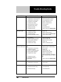
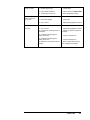
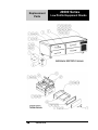
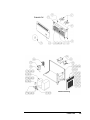
OPERATORS MANUAL
This manual provides
Installation & Operating instructions for
20000 SERIES
LOW PROFILE
EQUIPMENT
STANDS
NOTIFY CARRIER OF DAMAGE AT ONCE.
It is the responsibility of the consignee to inspect the
container upon receipt of same and to determine
the possibility of any damage, including concealed
damage. Randell suggests that if you are suspicious
of damage to make a notation on the delivery receipt. It will be the responsibility of the consignee to
file a claim with the carrier. We recommend that you
do so at once.
Manufacture Service/Questions 888-994-7636.
Information contained in this document is known to be
current and accurate at the time of printing/creation.
Unified Brands recommends referencing our product line
websites, unifiedbrands.net, for the most updated product
information and specifications.
P/N OMANUAL_MNL0503-01/07
1055 Mendell Davis Drive
Jackson, MS 39272
888-994-7636, fax 888-864-7636
randell.com
Table of Contents
page 2………………………………….…………Congratulations
page 3……………………………………Parts & Service Hotline
page 3………………………………...…Serial Number Location
page 4-7……………………………….Randell Limited Warranty
page 8…………………………………………Unit Specifications
page 9-10…..……………………………..……...Unit Installation
page 11………………………………………Electrical Diagrams
page 12-13………………………………………...Unit Operation
page 14-15……………………..………Preventive Maintenance
page 16-17..………………………………..……Troubleshooting
page 18-21…………………………….……..Replacement Parts
Congratulations on your recent purchase of Randell food service equipment,
and welcome to the growing family of satisfied Randell customers.
Our reputation for superior products is the result of consistent quality
craftsmanship. From the earliest stages of product design to successive steps
in fabrication and assembly, rigid standards of excellence are maintained by
out staff of designers, engineers, and skilled employees.
Only the finest heavy-duty materials and parts are used in the production of
Randell brand equipment.
This means that each unit, given proper
maintenance will provide years of trouble free service to its owner.
randell.com
2
In addition, all Randell food service equipment is backed by
some of the best warranties in the food service industry and by
our professional staff of service technicians.
Retain this manual for future reference.
NOTICE: Due to a continuous program of product improvement, Randell
Manufacturing reserves the right to make changes in design and specifications
without prior notice.
NOTICE: Please read the entire manual carefully before installation. If certain
recommended procedures are not followed, warranty claims will be denied.
MODEL NUMBER _________________________
SERIAL NUMBER _________________________
INSTALLATION DATE _____________________
The serial number is located in the mechanical housing.
800-621-8560
Randell Manufacturing Service
and Parts Hotline
randell.com
3
Warranty Policies
Congratulations on your purchase of a Randell Manufactured piece of equipment.
Randell believes strongly in the products it builds and backs them with the best
warranty in the industry. Standard with every unit comes the peace of mind that
this unit has been thoroughly engineered, properly tested and manufactured to
excruciating tolerances, by a manufacturer with over 30 years of industry presence.
On top of that front end commitment, Randell has a dedicated staff of certified
technicians that monitor our own technical service hotline at 1-800-621-8560 to
assist you with any questions or concerns that may arise after delivery of your new
Randell equipment.
PARTS WARRANTY
1. One year parts replacement of any and all parts that are found defective in
material or workmanship.
Randell warrants all component parts of
manufactured new equipment to be free of defects in material or workmanship,
and that the equipment meets or exceeds reasonable industry standards of
performance for a period of one year from the date of shipment from any
Randell factory, assembly plant or warehouse facility.
NOTE: Warranties are effective from date of shipment, with a thirty day
window to allow for shipment, installation and set-up. In the event
equipment was shipped to a site other than the final installation site,
Randell will warranty for a period of three months following installation,
with proof of starting date, up to a maximum of fifteen months from the
date of purchase.
2. Free ground freight of customer specified location for all in warranty parts
within continental U.S. Component part warranty does not cover glass
breakage or gasket replacement. Randell covers all shipping cost related to
component part warranty sent at regular ground rates (UPS, USPS). Freight
or postage incurred for any express or specialty methods of shipping are
the responsibility of the customer.
LABOR COVERAGE
In the unlikely event a Randell manufactured unit fails due to defects in
materials or workmanship within the first ninety days, Randell agrees to pay
reasonable labor rate performed by an Authorized Service Agent (ASA). Any
work performed by a non-ASA will not be honored by Randell. Please consult
Randell Technical Support (1-800-621-8560) for a complete listing of ASAs.
Warranties are effective from date of shipment, with a thirty day window to
allow for shipment, installation and setup. Where equipment is shipped to any
site other than final installation, Randell will honor the labor warranty for a
4
888-994-7636
period of ninety days following installation with proof of starting date, up to a
maximum of six months from date of purchase.
Temperature adjustments are not covered under warranty, due to the wide
range of ambient conditions.
To request a warranty approval number, call our Field Service Department at:
1-800-621-8560
WHEN OPTIONAL 5 YEAR COMPRESSOR WARRANTY APPLIES
1. Provide reimbursement to servicing company for the cost of locally
obtained replacement compressor in exchange for the return of the
defective compressor sent back freight prepaid. Note: Randell does
limit amount of reimbursement allowed and does require bill from local
supply house where compressor was obtained (customer should not
pay servicing agent up front for compressor).
2. Provide repair at the manufacturing facility by requiring that the
defective unit be sent back to Randell freight prepaid. Perform repair at
the expense of Randell and ship the item back to the customer freight
collect.
3. Furnish complete condensing unit freight collect in exchange for the
return of the defective compressor sent back freight prepaid.
(Decisions on whether or not to send complete condensing units will be
made by Randell’s in-house service technician).
WHEN OPTIONAL LABOR EXTENSION POLICY APPLIES
Randell will provide reimbursement of labor invoiced to an ASA for any
customer that has an optional labor extension of our standard warranty.
(Contracted rates do apply) Randell offers both 1 and 2 year extensions.
Labor extensions begin at the end of our standard warranty and extend out 9
months to 1 calendar year or 21 months to 2 calendar years from date of
purchase. Please contact Randell’s technical service hotline at 1-800-6218560 for details and any question on Authorized Service Agents (ASA).
WHEN EXPORT WARRANTIES APPLY
1. Randell covers all non-electrical components under the same
guidelines as our standard domestic policy.
2. All electrical components operated on 60 cycle power are covered
under our standard domestic policy.
3. All electrical components operated on 50 cycle power are covered for
90 days from shipment only.
4. Extended warranty options are not available from the factory.
ITEMS NOT COVERED UNDER WARRANTY
1. Maintenance type of repairs such as condenser cleaning, temperature
adjustments, clogged drains and unit leveling.
2. Randell does not cover gaskets under warranty. Gaskets are a
maintenance type component that are subject to daily wear and tear
and are the responsibility of the owner of the equipment. Because of
the unlimited number of customer related circumstances that can cause
gasket failure all gasket replacement issues are considered nonwarranty. Randell recommends thorough cleaning of gaskets on a
randell.com
5
weekly basis with a mild dish soap and warm water. With proper care
Randell gaskets can last up to two years, at which time we recommend
replacement of all gaskets on the equipment for the best possible
performance.
NOTICE: FOOD LOSS IS NOT COVERED UNDER WARRANTY
3. Repairs caused by abuse such as broken glass, freight damage, or
scratches and dents.
4. Electrical component failure due to water damage from cleaning
procedures.
QUOTATIONS
Verbal quotations are provided for customer convenience only and are
considered invalid in the absence of a written quotation. Written quotations
from Randell are valid for 30 days from quote date unless otherwise specified.
Randell assumes no liability for dealer quotations to end-users.
SPECIFICATION & PRODUCT DESIGN
Due to continued product improvement, specification and product design may
change without notice. Such revisions do not entitle the buyer to additions.
Changes or replacements for previously purchased equipment.
SANITATION REQUIREMENTS
Certain areas require specific annotation requirements other than N.S.F. &
U.L. standards. Randell must be advised of these specifications before
fabrication of equipment. In these special circumstances, a revised quotation
may be required to cover additional costs. Failure to notify Randell before
fabrication holds the dealer accountable for all additional charges.
CANCELLATIONS
Orders
canceled
prior
to
production
scheduling
entered
into
engineering/production and cancelled are subject to a cancellation charge
(contact factory for details).
STORAGE CHARGES
Randell makes every effort to consistently meet our customer’s shipment
expectations. If after the equipment has been fabricated, the customer
requests delay in shipment, and warehousing is required:
1. Equipment held for shipment at purchasers request for a period of 30
days beyond original delivery date specified will be invoiced and
become immediately payable.
2. Equipment held beyond 30 days after the original delivery date
specified will also include storage charges.
SHIPPING & DELIVERY
Randell will attempt to comply with any shipping, routing or carrier request
designated by dealer, but reserves the right to ship merchandise via any
responsible carrier at the time equipment is ready for shipment. Randell will
not be held responsible for any carrier rate differences; rate differences are
entirely between the carrier and purchaser. Point of shipping shall be
determined by Randell (Weidman, MI/Tucson, AZ/Jackson, MS). At dealer’s
6
888-994-7636
request, Randell will endeavor whenever practical to meet dealer’s request.
Freight charges to be collect unless otherwise noted.
DAMAGES
All crating conforms to general motor carrier specifications.
To avoid
concealed damage, we recommend inspection of every carton upon receipt.
In the event the item shows rough handling or visible damage to minimize
liability, a full inspection is necessary upon arrival. Appearance of damage will
require removing the crate in the presence of the driver. A notation must be
placed on the freight bill and signed for by the truck driver at the time of
delivery.
Any and all freight damage that occurs to a Randell piece of
equipment as a result of carrier handling is not considered under warranty, and
is not covered under warranty guidelines. Any freight damage incurred during
shipping needs to have a freight claim filed by the receiver with the shipping
carrier. Consignee is responsible for filing of freight claims when a clear
delivery receipt is signed. Claims for damages must be filed immediately
(within 10 days) by the consignee with the freight carrier and all cartons and
merchandise must be retained for inspection.
RETURNED GOODS
Authorization for return must first be obtained from Randell before returning
any merchandise.
Any returned goods shipment lacking the return
authorization number will be refused, all additional freight costs to be borne by
the returning party. Returned equipment must be shipped in original carton,
freight prepaid and received in good conditions. Any returned merchandise is
subject to a minimum handling charge (consult factory for rate).
INSTALLATION
Equipment installation is the responsibility of the dealer and/or their customer.
Randell requires all equipment to be professionally installed.
PENALTY CLAUSES
Dealer penalty clauses, on their purchase order or contractually agreed to
between the dealer and their clients are not binding on Randell. Randell does
not accept orders subject to penalty clauses. This agreement supersedes any
such clauses in dealer purchase orders.
EXPORT POLICY
All quotations for export sales will be handled by Dorian Drake International
(www.doriandrake.com), Randell’s export management organization.
*FOOTNOTES IN REFERENCE TO PARAGRAPHS ABOVE
1. Herein called Randell.
2. NET means list price less discount, warranty, labor policy, freight, Randell delivery and other
miscellaneous charges.
CASH DISCOUNTS WILL BE CALCULATED ON NET ONLY.
randell.com
7
Unit Specifications
20072SC shown
L
D
H
Drawers
12x20x4
Pan
Capacity
H.P.
Volts
Amps
NEMA
Ship
Wt.
20048SC
48"
32.5"
26"
(2)27"ext.
4
1/4
115
6
5-15P
400
20048SC-C4
48"
32.5"
24"
(2)27"ext.
4
1/4
115
6
5-15P
400
20072SC
72"
32.5"
26"
(4)27"ext.
8
1/3
115
7.4
5-15P
530
20072SC-C4
72”
32.5”
24”
(4)27”ext.
8
1/3
115
7.4
5-15P
530
20078SC
78”
32.5”
26”
(4)27”ext
8
1/3
115
7.4
5-15P
550
Model
Self Contained
20078SC-C4
78”
32.5”
24”
(4)27”ext
8
1/3
115
7.4
5-15P
550
20105SC
105”
32.5”
26”
(6)27”ext
12
3/8
115
12
5-15P
675
20105SC-C4
105”
32.5”
24”
(6)27”ext
12
3/8
115
12
5-15P
675
20048SCF
48”
32.5”
26”
(2)27”ext
4
1/3
115
8.7
5-15P
400
20072SCF
72”
32.5”
26”
(4)27”ext
8
1/3
115
8.7
5-15P
530
20105SCF
105”
32.5”
26”
(6)27”ext
1/2
115
10.9
5-15P
675
L
D
H
Drawers
12
12x20x4
Pan
Capacity
BTU
Volts
Amps
NEMA
Ship
Wt.
20042R
42”
32.5”
26”
(2)27”ext
466
115
3
N/A
330
20065R
65”
32.5”
26”
(4)27”ext
8
823
115
3
N/A
460
20092R
92”
32.5”
26”
(6)27”ext
12
1300
115
4
N/A
600
20042RF
42”
32.5”
26”
(2)27”ext
4
619
115
6
N/A
330
20065RF
65”
32.5”
26”
(4)27”ext
8
1093
115
6
N/A
460
20092RF
92”
32.5”
26”
(6)27”ext
12
1726
115
8.5
N/A
600
Model
Remote
4
Models with suffix SC are self-contained refrigerated units, SCF are self-contained freezer
units, and SC-C4 are self-contained refrigerated units with heavy-duty 4” casters.
Models with suffix R are remote refrigerated units.
8
888-994-7636
Unit Installation
SELECTING A LOCATION FOR YOUR NEW UNIT
The following conditions should be considered when selecting a location for your
unit:
1. Floor Load: The area on which the unit will rest must be level, free of
vibration, and suitably strong enough to support the combined weights
of the unit plus the maximum product load weight.
NOTE: Randell’s Low Profile Equipment Stands are designed to support
the weight of standard cooking equipment, such as griddles, fryers, and
cook top ranges. For non-standard cooking equipment or if there is a
question pertaining to weight load limits, consult the factory at 1-800621-8560.
2. Clearance: There must be a combined total of at least 3” clearance on
all sides of the unit.
3. Ventilation: The air cooled self contained unit requires a sufficient
amount of cool clean air. Avoid surrounding your equipment stand
around other heat generating equipment and out of direct sunlight.
Also, avoid locating in an unheated room or where the room
temperature may drop below 55° F or about 90° F.
INSTALLATION CHECKLIST
After the final location has been determined, refer to the following checklist prior to
start-up:
1. Check all exposed refrigeration lines to ensure that they are not kinked,
dented, or rubbing together.
2. Check that the condenser and evaporator fans rotate freely without
striking any stationary members.
3. Unit must be properly leveled; check all legs or casters to ensure they
all are in contact with the floor while maintaining a level work surface.
Adjusting bullet feet heights or shimming casters may be necessary if
the floor is not level. NOTE: Damage to equipment may result if not
followed. Randell is not responsible for damage to equipment if
improperly installed.
4. Plug in unit and turn on main on/off power switch.
5. Allow unit time to cool down to temperature.
If temperature
adjustments are required, the temperature control is located within the
cabinet on the front face of the evaporator coil behind the thermometer
(Note: The left set of drawers or center set for a 6 drawer unit must be
removed to access the temperature adjustment control).
6. Refer to the front of this manual for serial number location. Please
record this information in your manual on page 3 now. It will be
necessary when ordering replacement parts or requesting warranty
service.
7. Confirm that the unit is holding temperature. Set controls to desired
temperature for your particular ambient and altitude.
8. Allow your unit to operate for approximately 2 hours before putting in
food to allow interior of unit to cool down to storage temperature.
randell.com
9
NOTE: All motors are oiled and sealed.
NOTE:
FAILURE TO FOLLOW INSTALLATION GUIDELINES
RECOMMENDATIONS MAY VOID THE WARRANTY ON YOUR UNIT.
AND
ELECTRICAL SUPPLY: The wiring should be done by a qualified electrician in
accordance with local electrical codes. A properly wired and grounded outlet will
assure proper operation. Please consult the data tag attached to the compressor
to ascertain the correct electrical requirements. Supply voltage and amperage
requirements are located on the serial number tag located inside the mechanical
housing.
NOTE: It is important that a voltage reading be made at the compressor
motor electrical connections, while the unit is in operation to verify the
correct voltage required by the compressor is being supplied. Low or high
voltage can detrimentally affect operation and thereby void its warranty.
NOTE: it is important that your unit has its own dedicated line. Condensing
units are designed to operate with a voltage fluctuation of plus or minus 10%
of the voltage indicated on the unit data tag. Burn out of a condensing unit
due to exceeding voltage limits will void the warranty.
10
888-994-7636
Electrical Diagrams
randell.com
11
Unit Operation
Randell has attempted to preset the cold controls to ensure that your unit runs at
an optimum temperature, but due to varying ambient conditions, including
elevation, food product as well as type of operation, you may need to alter this
temperature.
It is strongly recommended that the drawers be kept closed when the unit is not in
use and between rush periods. This is especially important in the summer and in
kitchens exceeding 80° F. Do not leave the drawers open for prolonged periods of
time. Close after using.
NOTE: Even though your equipment stand was designed for heavy use, excessive
drawer openings should be avoided in order to maintain proper cabinet
temperature and eliminate the possibility of coil freeze-up.
Your equipment stand was equipped with a temperature adjustment control located
within the cabinet on the front face of the evaporator coil behind the thermometer
(Note: The left set of drawers or center set for a 6 drawer unit must be removed to
access the temperature adjustment control).
To adjust the temperature in refrigerated units:
A. To lower the temperature:
1. Turn the dial knob clockwise.
2. There are numbers to indicate settings. Keep the arrow on the
knob pointed within the numbered section of the arc.
3. Turning it clockwise beyond the numbered section can result in
freeze-up.
B. To raise the temperature:
1. Turn the dial knob counterclockwise.
2. There are numbers to indicate settings. Keep the arrow on the
knob pointed within the numbered section of the arc.
3. Turning it counterclockwise beyond the numbered section will
shut the compressor off.
NOTE: It is not recommended to turn the dial above 8 or below 1 on
the temperature control. If the adjustments still do not result
in proper temperature please contact the factory at 1-800-6218560.
C. If your temperature control is at the maximum setting and the cabinet
temperature still remains too low or too high, you may need to adjust
the pressure control.
1. Turn the right adjustment screw clockwise (1/4 turn at a time) to
a lower number for a colder temperature.
2. Turn the right adjustment screw counterclockwise (1/4 turn at a
time) to a higher number for a warmer temperature.
NOTE: Numbers on pressure control are pounds of pressure, not
degrees F.
NOTE: Do not adjust the differential screw.
To adjust the temperature in freezer units:
12
888-994-7636
A. Push and hold the “set” button until 12 appears and then release the
“set” button. 12 is the current set point temperature. NOTE: Standard
freezer units are preset to operate at 12° F.
B. To lower the temperature, push and release the up arrow 2 times until
10 is displayed. Push and release the “set” button one time. The new
set point, 10 will flash 3 times and then will be locked in.
C. To raise the temperature, push and release the down arrow 2 times
until 14 is displayed. Push and release the “set” button one time. The
new set point, 14, will flash 3 times and then will be locked in.
NOTE: It is recommended to only make changes of 2 degree increments
at a time. Allow for the unit to operate 24 hours between
adjustments. If the 2 degree adjustment is not enough another
adjustment can be made. The maximum highest setting is 25
degrees and the minimum lowest setting is 5 degrees. If the
settings need to go above or below this point there may be other
contributing factors as to the cause of the temperature variances,
please contact the factory at 1-800-621-8560.
randell.com
13
Preventive Maintenance
Randell strongly suggests a preventive maintenance program which would include
the following Monthly procedures:
1. Cleaning of all condenser coils. Condenser coils are a critical component in the
life of the compressor and must remain clean to assure proper air flow and heat
transfer. Failure to maintain this heat transfer will affect unit performance and
eventually destroy the compressor. Clean the condenser coils with coil cleaner
and/or a vacuum, cleaner and brush.
NOTE: Brush coil in direction of fins, normally vertically as to not damage or
restrict air from passing through condenser.
2. Clean fan blade on the condensing unit.
3. Clean and disinfect drains with a solution of warm water and bleach.
4. Clean and disinfect drain lines and evaporator pan with a solution of warm water
and bleach.
5. Clean all gaskets on a weekly if not daily basis with a solution of warm water
and a mild detergent to extend gasket life.
NOTE: DO NOT USE SHARP UTENSILS.
RECOMMENDED CLEANERS FOR YOUR STAINLESS STEEL INCLUDE THE
FOLLOWING:
JOB
Routine cleaning
Fingerprints and smears
Stubborn stains and
discoloration
Greasy and fatty acids,
blood, burnt-on foods
Grease and Oil
Restoration/Preservation
CLEANING AGENT
Soap, ammonia, detergent
Medallion
Arcal 20, Lac-O-Nu,
Ecoshine
Cameo, Talc, Zud, First
Impression
COMMENTS
Apply with a sponge or cloth
Provides a barrier film
Rub in the direction of the
polish lines
Easy-Off, Degrease It, Oven
Aid
Any good commercial
detergent
Excellent removal on all
finishes
Benefit, Super Sheen
Good idea monthly
Apply with a sponge or cloth
Reference: Nickel Development Institute, Diversey Lever, Savin, Ecolab, NAFEM.
NOTE: Do not use steel pads, wire brushes, scrapers, or chloride cleaners
to clean your stainless steel. CAUTION: DO NOT USE ABRASIVE
CLEANING SOLVENTS, AND NEVER USE HYDROCHLORIC ACID
(MURIATIC ACID) ON STAINLESS STEEL.
NOTE:
Do not pressure wash equipment as damage to electrical
components may result.
14
888-994-7636
Preventive Maintenance (cont.)
To remove and re-install drawer tracks, please refer to Figure 2 below for proper
installation instructions.
Figure 2
Proper maintenance of equipment is the ultimate necessity in preventing costly
repairs. By evaluating each unit on a regular schedule, you can often catch and
repair minor problems before they completely disable the unit and become
burdensome on your entire operation.
For more information on preventive maintenance, consult your local service
company or CFESA member. Most repair companies offer this service at very
reasonable rates to allow you the time you need to run your business along with
the peace of mind that all your equipment will last throughout its expected life.
These services often offer guarantees as well as the flexibility in scheduling or
maintenance for your convenience.
Randell believes strongly in the products it manufactures and backs those products
with one of the best warranties in the industry. We believe with the proper
maintenance and use, you will realize a profitable return on your investment and
years of satisfied service.
randell.com
15
Trouble Shooting Guide
SYMPTOM
POSSIBLE CAUSE
PROCEDURE
Unit doesn't run
1.
2.
3.
4.
5.
6.
7.
8.
9.
No power to unit
Temperature control turned off
Temperature control faulty
Compressor overheated
Condenser fan faulty
Overload protector faulty
Compressor relay faulty
Defrost timer faulty
Compressor faulty
1.
2.
3.
4.
5.
6.
7.
8.
9.
Plug in unit
Check temperature control
Test temperature control
Clean condenser coil
Service condenser fan
Test overload
Test relay
Test defrost timer
Call for service at 800-621-8561
Unit short cycles
1.
2.
3.
4.
Condenser coil dirty
Condenser fan faulty
Compressor faulty
Overload repeatedly tripping
1.
2.
3.
4.
Clean coil
Service fan and motor.
Call for service at 800-621-8561
Check outlet voltage
Unit runs constantly
1.
2.
3.
4.
5.
Frost build-up
Drawer not sealing properly
Drawer gasket damaged
Condenser coil dirty
Condenser fan faulty
1.
2.
3.
4.
5.
Defrost evaporator
Check drawer seal
Replace drawer gasket
Clean coil
Service condenser motor
Unit not cold enough
1. Temperature control set too
high
2. Temperature control faulty
3. Condenser coil dirty
4. Drawer not sealing properly
5. Drawer gasket damaged
6. Evaporator fan faulty
7. Evaporator iced up
8. Refrigerant leaking or
contaminated
1. Adjust control to lower setting
2. Test control
3. Clean coil
4. Check drawer seal
5. Replace drawer gasket
6. Service evaporator fan
7. Defrost evaporator, test defrost
heater, test thermodisc, test defrost
timer
8. Call for service at 800-621-8561
Unit too cold
1. Temperature control set too low
2. Temperature control faulty
1. Adjust control to raise setting
2. Test control
Unit doesn’t defrost
1. Defrost heater faulty
1. Test defrost heater
2. Defrost thermodisc faulty
2. Test thermodisc
3. Defrost timer faulty
3. Test defrost timer
16
888-994-7636
Moisture around
drawer or frame
Ice in drain pan or
water in bottom of
unit or floor
Unit noisy
1. Breaker strips faulty
1. Inspect strips
2. Frame heater defective
2. Call for service at 800-621-8561
3. Temperature set too low
3. Raise temperature setting
1. Drain tube clogged
1. Clean drain
2. Unit not level
2. Adjust leveling leg/shim casters
1. Unit not level
1. Adjust leveling leg/shim casters
2. Compressor mountings loose or
hardened.
2. Tighten or replace compressor
mountings
3. Condenser fan damaged or
hitting fan shroud
3. Inspect condenser fan
4. Evaporator fan damaged or
hitting fan shroud
4. Inspect evaporator fan
5. Mechanical compartment louver
rattling
5. Bend or align tabs to reduce
noise. Replace if necessary.
randell.com
17
Replacement
Parts
18
888-994-7636
20000 Series
Low Profile Equipment Stands
randell.com
19
ITEM
DESCRIPTION
PART #
1
Drawer Front, 27", Top
RP FRT05T
1A
Drawer Front, 19", Top
RP FRT118
1B
Drawer Front, 32", Top
RP FRT35T
2
Drawer Front, 27”, Bottom
RP FRT05B
2A
Drawer Front, 19”, Bottom
RP FRT119
2B
Drawer Front, 32”, Bottom
RP FRT35B
3
Sculptured Handle, 12-13/16”
HD HDL130
4
Dial Thermometer
HD THR9901
5
Mechanical Housing Louver, 20048SC & 20072SC only
RP LVR0321
5A
Mechanical Housing Louver, 20078SC only
RP LVR0505
5B
Mechanical Housing Louver, 20105SC only
RP LVR0322
5C
Mechanical Housing Louver, 20048SCF & 20072SCF only
RP LVR0326
5D
Mechanical Housing Louver, 20105SCF only
RP LVR0327
5E
Mechanical Housing Louver, 20042R only
RP LVR0323
5F
Mechanical Housing Louver, 20065R only
RP LVR0324
5G
Mechanical Housing Louver, 20092R only
RP LVR0325
5H
Mechanical Housing Louver, 20042RF only
RP LVR0506
5I
Mechanical Housing Louver, 20065RF only
RP LVR0507
5J
Mechanical Housing Louver, 20092RF only
RP LVR0508
6
4 ½” Heavy Duty Casters w/locking mechanism
HD CST030
6A
4 ½” Heavy Duty Casters w/out locking mechanism
HD CST031
6B
5 ½” Heavy Duty Casters w/locking mechanism
HD CST0213
6C
5 ½” Heavy Duty Casters w/out locking mechanism
HD CST0212
7
Caster Shim Plate (20pc)
RP KIT0412
8
6” Stainless Steel Legs w/adjustable bullet feet
HD LEG9902
9
Mounting Plate for 27” Drawer
RP MPT027
9A
Mounting Plate for 19” Drawer
RP MPT019
9B
Mounting Plate for 32” Drawer
RP MPT032
10
Thumb Screw
HD PIN107
11
Drawer Track, 2pc. Set (Jan 1997-present)
RP TRK05SM
11A
Drawer Track, 1pc. Pin mounted (1993-1997)
RP TRK05P
12
Roller Bearings for Drawer (Jan 1997-present)
HD BRG210
Screw for HD BRG210 draw bearing
FA SCW6002
Drawer Frame, 27” Extendable
RP FRM127E
13A
Drawer Frame, 19” Non-extendable
RP FRM019
13B
Drawer Frame, 32” Extendable
RP FRM132E
14
Drawer Gasket, 27” DR. FR. 24.75 X 7.25 PRESS IN
IN GSK1070
14A
Drawer Gasket, 19” DR. FT. 16.75 X 7.25 PRESS IN
IN GSK1081
14B
Drawer Gasket, 32” DR. FT. 29.75 X 7.25 PRESS IN
IN GSK1075
14C
Drawer gasket, 27” DR. FT. 24.75 X 7.25 SCREW IN
IN GSK195
14D
Drawer gasket, 32” DR. FT. 29.75 X 7.25 SCREW IN
IN GSK196
15
Fan Mounting Bracket for Coil Assembly
RP SHD107
16
Mounting Support Bracket for Coil Assembly
RP BRK006
17
Evaporator Fan Motor w/ blade (April 1998 – Present)
EL MTR2338
17A
Evaporator Fan Motor no blade (prior to 4/1998)
EL MTR0230
17B
Evaporator Fan Blade (prior to 4/1998)
RF FAN005
17C
12A
13
Evaporator Fan Bracket (prior to 4/1998)
RP BRK1050
18
Dial Temperature Control for cooler
HD CNT200
18a
Dial Temperature control for freezer
HD CNT100
19
Plastic Bottom 18.25 X 4.25 Drain comes out back
RP DRP107
20
Heating Element for Coil Assembly, Freezer Units only
EL ELM9903
21
TXV Valve for Coil Assembly
134A COOLERS
RF VLV200
21A
TXV Valve for coil assembly
404A FREZZERS
RF VLV404
22
20
Evaporator Coil
888-994-7636
RP COI107
22A
Evaporator Coil Assembly, Refrigerated Units only
RF CSY0401
22B
Evaporator Coil Assembly, Freezer Units only
RP CSY0402
23
Shield Panel for Coil Assembly
RP PNL107
24
Power Cord, Male 9’
EL WIR461
25
Rocker On/Off Switch
EL SWT140
26
Power Cord, Female 12”
EL WIR469
27
Compressor, 20048SC
RF CMP010-134
27A
Compressor, 20072SC, 20078SC
RF CMP020-134
27B
Compressor, 20105SC
RF CMP0104P
27C
Compressor, 20048SCF, 20072SCF
RF CMP031P
27D
Compressor, 20105SCF
RF CMP9902P
Condensing Unit, 20048SC
RF CON0004
28A
Condensing Unit, 20072SC, 20078SC
RF CON9803
28
28B
Condensing Unit, 20105SC
RF CON0006
28C
Condensing Unit, 20048SCF, 20072SCF
RF CON0003
28D
Condensing Unit, 20105SCF
Condenser Fan Motor, 20048SC, 20072SC, 20078SC, 20048SCF,
20072SCF
RF CON9901
29A
Condenser Fan Motor, 20105SC
EL MTR0102
29B
Condenser Fan Motor, 20105SCF
Condenser Fan Blade, 20048SC, 20072SC, 20078SC, 20105SC,
20048SCF, 20072SCF
EL MTR300
30A
Condenser Fan Blade, 20105SCF
RF FAN007
31
29
30
RF MTR0104
RF BLD0101
Condensing Unit Shroud, 20048SC
RP SHD0505
31A
Condensing Unit Shroud, 20072SC, 20078SC
RP SHD0506
31B
Condensing Unit Shroud, 20105SC
RP SHD0507
31C
Condensing Unit Shroud, 20048SCF, 20072SCF
RP SHD0508
31D
Condensing Unit Shroud, 20105SCF
RP SHD0509
32
Dixell Temperature Control for Rail
RP CNT0207
33
Dixell Face Plate
RP FPT0501
34
Dixell Mounting Housing Bracket
RP BRK0509
35
Solenoid Valve, Remote Units only 120V.
RF SOL9801
randell.com
21