1
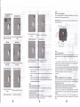
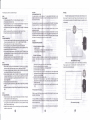
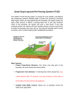
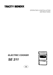
Smart Dog In-ground Pet Fenc ing System HT-023
This hidden HT-023 fencing system is among the most reliable , cost-efficient pet containment
•
1 x Adjustable receiver collar;
•
1 x 6 Volt battery for collar;
•
boundary wire of 300 metres;
2 x Extra metal contact points ;
systems available today . A buried wire transmits a harmless radio signal. When you dog
approaches the boundary, the signal causes the dog's collar receiver to deliver a warning beep
first. If your dog continues closer to the boundary, the system will issue a mild shock . If your dog
continues further, the system will issue stronger shocks until your dog returns to within the
boundary your have set up. Your dog will naturally seek to avoid correction, and is content
staying within established boundaries.
1x
should take place using a long leash to keep you in control of the situation . Also realize that an
aggressive animal could tum against the handler upon receiving the stimul us. Th erefore, if you
feel your dog has an aggressive behaviour andlor it has a history of agg ressive beh aviour , you
should consult a certified animal behaviourist before using this product.
•
20 x Traini ng flags ;
•
1 x Test bulb;
•
•
4 x screws ;
1 x User's manual.
SECTION 1
INST RUCTI ONS FOR SETTING UP YOUR CONTAINMENT SYSTEM
STEP 1
PREPARE A LAYOUT OF YOUR CONTAINMENT AREA
A. Des ign and Draw Diag ram
Other Items you may need:
SCrewdriver ;
6OUND. 6HOCK
STIMULUS IS
DELIVERED IN
SHORT PULSES.
Straight edged spade or a lawn edger ;
Wire stripping pliers;
Electrical tape;
Waterproofing compound (e.g . silicone cau lk):
Patching compound for your type of drive way or sidewalk;
PVC pipe if crossing a gravel or dirt drive way, pond or lake;
Pencil , Ruler or Protractor;
Drill with drill bit or masonry bit if drilling through wood or concrete;
Additio nal Bou ndary Wire.
CAUTION
Main Features:
Pulsed Propo rtional Stimulus-The closer your dog gets to the boundary, the more
Please take a few minutes to read the instruction manual prior to your first use.
intense the shock will be;
Pr ogressi ve To ne St lm ulus-A warning tone will be issued first , then a shock stimulus if
For best results, follow these impo rtant rules:
your dog continues to move closer to the boundary;
Var iable Field Width Co nt rol- Allows you to precisely control the width of the signal
•
field;
•
A low battery may cause intennittent operation. DO NOT USE if yo u suspect a low
battery .
Aud ible and Visual W ire Break Ind ic ators-Should your buried wire ever break , a loud
sonic alarm will sound accompanied by a flashing light;
The electronic dog collar is intended only for use on dogs .
•
Allow your dog to get used to the collar before you begin training. You want your dog to
accept the collar as part of a routine, not to associate the colla r with corre ction .
Speed Detect Ant l·Run th roug h-Th e faster your dog is moving , the quicker the higher
level of intensity is issued;
•
Built-In LIghtn in g Protect lo n-Protects transmitter from power surges caused by
• . NEVER perform set-up procedures when the collar is on your dog .
DO NOT leave the collar on your dog for more than 12 hours per day .
lightning strikes ;
•
Mu lti ple Collar Operation-Add as many collars as you like to contain as many animals
•
KEEP OUT OF THE REACH OF CHILD REN.
you have . There is no limit to the number of collars it can control.
•
Read all instructions before using this prod uct.
An electronic collar should only be used under close supervision by the dog's owner.
Up to 5000 square metre range (over 1.2 acre) .
IMPORTANT
Pac ka ge Con tents :
• 1 x Indoor wall -mounted transmitter;
•
Realize that because individual dogs have uniq ue temperaments, the re is no way of knowing
how your dog will react to its introduction to this product, For the safety of your dog, initial train ing
1 x Power plug ;
o
Prepare a diagram of the area you want to contain your dog . A diagram will help to avoid
unforeseen obstacles. Include the location of house , driveway, pond, garde n, swimming pool, etc.
If your neighbour has a containment system installed, mark the location of the buried wire on
your diagram.
B. Contact Utility Company
Contact your utility companies to mark any buried utility lines . Be sure to incl ude the buried lines
on your drawing because these utility lines will affect the place ment of you r wire .
C. Determ ine L oc atio n of Wall Transmitter
The transmitter can be mounted to a wall near any standard 240·volt household outlet with the
included screws . It wilt withstand freeZing temperatures, but it is not waterp roof. There fore , it is
best to locate the transmitter in an enclosed area. Install the transmitter at least three feet from
any large metal objects such as breaker boxes , water heaters, metal garage doors, or washer
andlor dryer . When insta lling the transmitter make sure the wire is not cut off or pinche d by a
window , door or garage door . When drilling holes , make sure there are no electrical wires , nails
or screws inside the area you are drilling .
D. Determine the Exit Route of Your Boundary W ire from the Transmitter to the Outside
Containment Area
Since your transmitter must be mounted in an enclosed area to protect it from the weather, give
careful consi deration on where the wire exits to the exterio r. Exis ting ope nings such as a win dow,
door or utility line hole may provide easy access to the outside . You may need to drill a hole
thro ugh the exterior wall.
e
STEP 2
ADD PROPOSED WIRE LOCATION TO YOUR DRAWING
Mark your diagram with the proposed location of your wire . Th is will provide an easy reference
as you install the wire. For the system to work properly , the wire must make one conti nuous loop.
The signa l is trans mitte d from one terminal of the transmi tter , through the wire and back to the
othe r terminal.
Example Installation Diagrams
Zones within Zones
STEP 4
INSTALL THE WALL TRANSMITTER
Install the wa ll transmitter close to a standard 24 0-volt household outlet. 0 0 not p lug the
transmi tter to the outlet until the bou ndary wire is in place.
Basic Singia Wire Zona
I
IMPORT A NT NOTE : We recommend that you unplug the transmitter and disconnect the fence
wire during lightning storms.
Your pet has run of the hous e and
Your pe t has run of the house and front yard .
b ac k ya rd.
Keeps your pet safely away from Your pet has a 360 degr ee perimeter to roa m
gardens. poo ls, and othe r areas .
with in.
------Dual Zones
Front & Rear Barr ier Zones
Side Barrier Zones
Open Back Zone
If bur l de wire br. .tr. •• loud
'eOni calAM1 _ i 1 1 IIOUDd
STEPS
LA V OUT THE PERIMETER WIRE
IMPORTA NT NOTE : Do NOT bury the wi re until you have tested the sys tem and are sure it is
working property. Do NOT nick or scra pe the wire duri ng installatio n. Improper function may
result.
Yo ur pet has full access to both Your pet has full access to the front or rear , but
sides , but not to the front or rear .
not to the sides .
Keep pets sepa rate d, or to
. preven t run-tnru.
Th is lets yo ur pet have access to the lake or
other rea r area .
Single loop· Back Yard Zone
Single Loop· Front Yard Zone
IMPORTANT NO TES FOR WIRE PLACEM ENT:
•
Do NOT run the loop within
2 mete rs pa rallel to electri cal , telephone, cab le TV, or other
buried wire in the yard .
•
Do NOT run one section of wire within 3 meters of ano ther section or the signal may
cancel.
•
•
00 NOT run your wIre within 3 mete rs of any adjacent containment syste m's wire .
00 NOT run your wire within 3 ce nti-meters of any steels bars under concrete ground
otherwise signal strength will be red uced,
STEP 3
J
ESTIMATE TH E AMOUNT OF WIRE NEE OED
HT-023 model include s 300 metres of bou ndary wire . It can enclose an area of over 1.2 acres.
Yo ur pet has run o f the hou se an d
Vour pet has run of the house and fron t yard .
b ac k ya rd.
Double Loop · Back Vard Zone
Double Lcop , Front Vard Zona
The amount of wire needed is de termi ned by several factors:
(a)Totalarea to be contained;
(b)Using a double loop . This requires twice as much wire ,
(c)Slze of the signal field . The sIgnal field is the distance from the wire to the place where the
collar receiver first activates. A 3 to 4 met ers wide field is preferred .
1. Use your drawing as a reference. Begin laying the wire around the perimeter of your
containment area to form a continuous loo p. Use gradual turns at the comers with a minimum of
1meter radius. This provides a mo re consistent signal fie ld .
2. If you are using more wire than initially supplied with your co ntainment system . the wire
con nections must be waterproo f to provide a sealed connection between the wires . Do not use
electrical tape or twisted wire nuts. This will cause an intermittent signal or disarm the sys tem ,
3. Conti nue aro und your perimeter until you return to the start of the loop.
4. Cut the wire .
STEP 6
CONNECT THE PERIMETER WIRE TO THE WALL TRANSMITTER
The wi re from the perimeter to the wall transmitter should be twisted to cancel th e sign al. This
allo ws the dog to cross the area without receiving a correction. It also elim inates possible
interference fro m electrical wires . etc .
1. Me asur e the distance from the wa ll transmitter to the edge of the perimeter wi re.
2. Beca use twisting th e wire decreases the length of the wi re, multiply the distance by 1¥.I .
3. Me asur e and cut two wires of equal lengths of the above measurement.
4. Hold the two ends of the wire side by side and twist them together. The wires can be twisted
manually until the twists are 6 to 12 cm apart , The tighte r the wire Is tw isted the better the signal
cancellation.
5. Pu ll the tw:isted wire to the perimeter locat ion of the two ends of your boundary wire loop .
Splice the ends of the twisted wire to the ends of the boundary wire ONLY with waterproof
splices.
6. Put the twisted wires through the existing open ing or drilled hole so
transmitter.
7. Strip off about 1 em of insulation from the end of each tw isted wire .
8. Insert the wires into the termi na ls of the tra nsmi tter.
9. Plug the power adapte r into a sta ndard 240-volt ho useho ld outlet.
10. Conn ect the power adapter to the transmitter's power port.
rtcan
be connected to the
STEP 7
VERIFY TRANSMITTER IS FUNCTIONING PROPERLY
To verify the transmitter is functioning property, look for OK and Power lights on the tra nsmitter.
When both of them tum green , it means the transmitter is receMng powe r, both wires are
connected , and the wire forms an unbroken , continuou s loop . If the Break light turns red. it
means that one or both wires are not property co nnect ed or both wires are co nnect ed but the
wi re is brok en . Correct the problem and retest.
STEP 8
SET UP YOUR COLLAR RECEIVER
Insert 6V 4LR 44 battery in th e co llar receiver following the positi ve (+) and neg ative (-) signs
inside the battery compartment. Incorrect Installation could cause permanent damages to some
electronic pa rts . When the indicat or ligh t turns green, it means the collar rece iver is working
property. When the indicator light turn s red , it means battery is run ning down and needs to be
replaced.
PushDown
IMPORTANT NOTE : Do NOT place the collar receiver on your dog until the containment system
has been tested and the signal field adjusted.
STEP 9
TEST THE CONTAINMENT SYSTEM
DO NOT TEST THE CONT AIN M ENT SYSTEM WITH THE COLLAR RECEIVER ON TH E DOG .
You must man ually test the containment system to verify that the sig nal is pro pe rly tra nsmitted
throug h the wi re. Use the supplied test light.
Select a section of straight boundary wire that is at least 50 feet long. Attach the supplied test
light to the receiver probes and ho ld the collar receiver at yo ur dog 's neck hei ght. Slow ly walk the
collar toward the boundary wire . Usten for the warning tone an d watch for the test light to light.
The wider you can make the containment field , the less chance your dog can run through. Adjust
the FIELD WIDTH as necessaoy and test again.
Test in a number of different areas unti l you are satisfied there are no wire breaks and the
syste m is functioning properly.
Next walk all around the "sate" part of the yard to ensure there are no stray signals, particularty
near the twisted wir e coming from the transmitter . Test collar in and around the inside of the
house as we ll. Signals from Cable TV , electrical or telephone lines can 'couple" ca using stray
signa ls insi de and outsi de the house that can activate the dog 's co llar accidentally. If you do
encoun ter this pheno menon, you r boundary wire is probably too close to these out side lines and
will need to be moved or modified . Containment coll ar s sho uld not be worn inside the house .
STEP 10
ADJUST THE SIGNAL FIELD WIDTH
The signal field Is the distance from the wire to the place where the co llar rece iver first acti va tes .
The Field Wtdth Knob adjus ts the size of the signal field, not the correction intensi ty. Turning the
knob clockwise increases the signal field width ; turn ing it counter-clockwise dec reases it. Turning
the knob com pletely counter-ctockwise switches oN the transmitter po wer.
Follow th e instructions in Step 10-to test the signal field width . Walk the enti re perimeter to be
sure that the signa l field is consistent throughout your contai nment area . The signa l field sho uld
exte nd a minimum of 2 meters on eithe r side of the wire (creati ng a 4 meter wide field) . A 3 to 4
me ter wide field is prefe rred. The wider the signal tl Id width, the less chance that a dog ca n run
thro ugh th e field.
IMPORTANT NOTE: If the Field Width knob is rem oved or the posit ion of the knob is alte red by
turning it clockwise or co unter-dockwi se, you mu st atways check the signal field for th e desired
setti ng . Refer to Step 10, tes t me Co ntain ment Sys t m.
STEP 11
INSTALL THE BOUNDARY WIRE
Tool. Needed - Straight-ed ged spade, wire cutt er I stripper, and standard screwdriver. If you
plan to run the wire across co ncrete, you will also need a caulk gun . silico ne caulkin q. and a
ci rcula r saw with a masonry blade .
Burying the WIre · Th e wire does not have to be bu rled, but for protection you probably want to
bury it at least one inch underground. Start by diggi ng abo ut 7 to 10 cm deep where th e wire first
enters the ground near the trans mitter and co ntinue arou nd the path of th e loop wire.
Note: When covering a larg e area , you ma y wish to use a trenching mach ine to cut into the
placed in the trench by ha nd. A commercial
ground. However, we recommend that the wi re
wire-placing machine may break the wi re.
Driveways I Sidewalks - W hen crossing an asphalt driveway, mak e a 2 em dee p cut across the
driveway using a circu lar saw and masOnry blad e. Place the wi re in th e c rack and seal with
asphalt sealant. On driveways and sidew alks , if an ex pansion joi nt is available, simply place the
wire in the jo int and seal wtth an outdoo r ca ulk. When crossi ng gra vel , b ury th e wire at least 7 em
dee p. Use an old ga rden ho se or plas tic PVC pipin g to protect the wi re. In wa ter , anchor the wire
wit h large rock s. Protect the wire with an old garden hose or plasti c PVC piping.
STEP 12
INSTALL THE BOUNDARY TRAINING FLAGS
After installing the wire , retest the contai nment system as described in Step 10, Test the
Containment Sys tem . Verify that the signal field wktth is consistent by following the instructions
in Step 11. Adjust the Signal Field Width. As you are retesting and verifying the system , install
the boundary training flags . Place the flags where the warni ng ton e is first heard as you
approach the wire . The flags should be placed at the edge of the sign al fiel d width, not directly on
the wire . This will add a visual cue to the audio warnin g tone and he lp your dog to learn the
boundaoy .
o
STEP 13
FITTING THE COLLAR TO YOUR DOG
IMPORTANT NOTE: Never leav e th e colla r rece iver on the dog for longe r than 12 hours a day.
Leavi ng the colla r on the dog for ext ended periods co uld result in skin irritatio n. Check your dog's
neck periodically for skin irritation.
A. Probe.
Ma ke sure both probes contact the dog 's skin. If needed, a small amount of hair remov al
or thin ning will Improv e probe contact with the skin .
Use short probes for sho rt-ha ired dogs . Use long probes for lon g-h aired dogs.
Finger-tighten the probes , then tum the m one add itiona l revolution . Do not over -tigh ten.
Check the tightne ss of the probe s regu larly to pre vent loss of the rece iver box.
B. Collar Strap
To prevent acci dental correction inside the home , remove the collar from the dog's neck
when it comes inside .
Place th e co llar around the dog 'S neck with the receiver bo x under the chin . The collar
mu st be on relat ively tight to keep th e probes making skin co ntact without restricting
brea thing. You should be able to slide only on e finger under the strap at the back of the
dog 's neck .
Always mak e sure the co llar is function ing property BEFORE putt ing it on the dog .
Remov e othe r metal collars whe n the dog we ars the co ntainme nt coUar. Metal colla rs may
interfere with proper operation.
Remove the collar and trim the excess strap.
SEcnON2
HOW THE CORRECnON WORKS
1. Pre-Correction Warning Tone : When the dog reac hes the edge of the signal field in the yard ,
lasts about Iwo seco nd s. If the dog does not retum to the safe part
of the yard , it will rece ive a co ntinuous correction until it returns to the safe area.
rtwill hear a waming ton e that
2. Run-Through Prevention: The receiver automatically increases th e co rrection as the dog
en ters the signa l field . The dog cann ot 'run thro ug h' the signa l field wrthout receiving a stro ng
co rrection .
SEcnON3
TRAINING YOUR DOG
To get the most out of your containment system when training. keep these tips in mind :
To prevent acc idental correction ins ide th e ho me, rem ove the collar from the dog 's nec k
when it comes inside.
Alw ays make su re the col lar is functioning prope rly BEFORE putti ng rt on the dog . Ve rify
the syst em is operating prope rly and the fiel d width is appropriate as de scribed in Section
I , Step 11. Adjust the Signal Field Width .
Stay positive an d playful du ring the training session.
Kee p traini ng sess ions brief. Never co ntinue a sessi on after your dog has lost interest.
Take a brea k to rest or play .
ALWAYS praise you r dog for good beh aviour .
The follow ing steps outline a successful training plan:
STEP 1
FLAG TRAINING
1. Turn the wall transmitter "orr so no corrections will be given to your dog.
2. Place the collar receiver on your dog .
3 . Place a long leash on your dog . Play with your dog in the safe area of the yard for 2-4
minutes . Do not allow your dog to run free or cross the flag lines .
4 . Walk towards the flags. Reach down and shake a flag. Say "bad flag- in a disapproving
tone .
5. Return to the centre part of the yard and play with your dog . Reward with treats.
6. Repeat this exercise several times in various locations of the yard.
STEP 2
THE FIRST CORRECTION
1. You need to reset the signal field width before placing the collar receiver on your dog .
Follow the Instructions outlined in Sect ion 1, Step 11, Adjust the Signal Field Width .
2. Place the collar receiver on your dog in the safe area of the yard.
3. Place a long leash on your dog . Play with the dog In the safe area of the yard .
4. Walk towards the flags . If your dog tries to avoid the flags , praise and reassure your dog .
5. Repeat this step in other locations of the yard.
6. Allow no more than three correcti ons in a day or seven in a week . This depends on your
dog's stress tolerance . Most dogs only receive a few correcti ons during the training phase;
they respond to tone very quickly .
7, Reward your dog when it avoids the flags, even if a correction is issued .
8. Play in the safe zone with your dog before ending this train ing session.
STEP 3
ON·LEASH PROOFING
1. With the collar on your dog and the wall transmitter "on", play with your dog (on leash) in
the safe area. After a few minutes of play , toss a toy or treat through the lIags.l 0
2. If your dog runs through the flags to chase the toy, wait for the startled response and pull
your dog back into the safe area . Praise and reward your dog .
3. Reinforce training by shaking a flag. Say -bad flag - with a disapprovi ng tone. Consider
increasing the signal field area . If you choose to increas e the signal field area, remove the
collar from your dog , increase the signal field, and retest. Refer to Section 1, Step 11,
Adju st the Signal Field .
4. Repeat this exercise in other locations of the yard .
5. Praise your dog when it avoid s the flags . Stay positive and playful during the training
session .
6. When your dog refuses to run through the flags 20 co nsecutive tim es, proceed to the next
step .
STEP 4
OFF·LEASH PROOFING
1. Follow the instructions In Step 3, On-Leash Proofing excep t drop the leash on the ground .
It will be available if you need to retrieve your dog.
2. If your dog gets through the signal field du ring this phase , qu ickly remove the collar. Bring
your dog back into the safe area. Put the collar back on your dog . Reinforce "bad flag train ing. Praise and reward your dog.
3. Repeat this on-leash training until you are con fident that your dog will Ignore temptations
outside the containment area.
SECTION 4
SYSTEM MAINTENANCE TIPS
Your system requires very little maintenance . The battery-opera ted co llar receiver is water
resistant and should not be Immersed in any liquid. This will cause damage not covered und er
the manufa cturer's warr anty.
The wall transmitter is not waterproo f and must be protected from the weather. A close lightn ing
strike may damage the unit. Unplug the transmitter and disconnect the wires during storms.
Warning:
1.The system included a boundary wire of 300 metres. If there still have ary weres
atter you used it to make the fence wire. Please cut down the remanent wire. You can't
use the remanennt wire connect with the transmitt er.Otherwise the transmitter will can't
working proper1y.
Do not attempt to d ismantle or repair any of the system components; this wilt void the
manufac ture r's warranty.
Test the system once a week to make sure the collar receiver is working proper1y. Also , testing
the system will verify th e field width setting is co rrect. To test, attach the supplied test light to the
colla r receiver·probes. Holding the receiver by the case, NOT by the probes . walk Into the signal
field . Usten for the warni ng tone to sound and the test light to illuminate.
SECTION 5.11
TROUBLESHOOTING GUIDELINES
A. Dog Is not responding to correction:
• Adju st the collar lit.
• Trim the dog's hair or use longer probes to make better skin contact.
• Change the batt ery In the collar receiver.
8. System Test Procedure:
Whene ver you experience a ma lfunction. you will need to do a Test Loop to determine which
component· collar, wall transmitter, or yard wire - Is not working . To perform the Test loop
procedur e:
(This connect way Is wrong)
2.lf there are any wrong operation caused the system working unconventionally.
1. Make a test loop using
a piece of wire at least 4 meters in length.
2. Remove the existi ng wIre from your wall transmitter.
3. Inse rt the two ends of the test loop wire Into the wail ira nsmitter.
Please unplug the power of the transmitter.After 5 minutes,The system will work
properly when you plug the power again.
4 . Tum the field width knob to a low setting .
5. Place the test light on the collar receiver. With the co llar in hand, move outside the field
and approach the test loop. Make a mental note ot the distance between the co llar and
the wire when the collar activates.
6. Tum the field width knob to a medium setting .
7. Back away trom the wlr. and approach it again. Determine the distance between the
collar and the wire when the colla r activa tes. The distance should be greater on the
medium rang lIell ing .
8. If more than one collllr recei ver is used with the system . repeat the above test on each
collar.
A.aults of Sy tem Telt Procedures :
If there II no greon POWER light on the wall transmitter with the test loop wire in place, the wall
tran8mltt r la ma lfunctioning ,
If the green POW A and OK lights are solid on the wall Iransmitter, but the collar does not
actlva le on th te t loop wlr., the collar receiver III not working . Change the battery in the collar
receiver and r pesl the t I t.
If the rod Br k light on the tr nsm itter tu ms on 10 elher with be ping sound, the problem is in
the yar d wlr• .
(This connect way Is right)