1
User's Manual
Verb
24 32 Bit Digital Effects Module
R
LTO
www.altoproaudio.com
Version 2.0 Dec. 2002
English
SAFETY RELATED SYMBOLS
External Connection
CAUTION
RISK OF ELECTRIC SHOCK
DO NOT OPEN
This symbol, wherever used, alerts
you to the presence of un-insulated
and dangerous voltages within the
product enclosure. These are voltages
that may be sufficient to constitute the
risk of electric shock or death.
This symbol, wherever used, alerts
you to important operating and maintenance instructions. Please read.
Protective Ground Terminal
Always use proper ready-made insulated
mains cabling (power cord). Failure to do
so could result in shock/death or fire. If
in doubt, seek advice, from a registered
electrician.
Do not Remove any Covers
Within the product are areas where high
voltages may present. To reduce the risk
of electric shock do not remove any
covers unless the AC mains power cord
is removed.
AC mains (Alternating Current)
Covers should be removed by qualified
service personnel only.
Hazardous Live Terminal
No user serviceable parts inside.
ON: Denotes the product is turned on.
Fuse
OFF: Denotes the product is turned off.
To prevent fire and damage to the
product, use only the recommended
fuse type as indicated in this manual.
Do not short-circuit the fuse holder.
Before replacing the fuse, make sure
that the product is OFF and disconnected
from the AC outlet.
WARNING
Describes precautions that should be
observed to prevent the possibility of
death or injury to the user.
CAUTION
Describes precautions that should be
observed to prevent damage to the
product.
WARNING
Power Supply
Ensure that the mains source voltage
(AC outlet) matches the voltage rating
of the product. Failure to do so could
result in damage to the product and
possibly the user.
Unplug the product before electrical
storms occur and when unused for
long periods of time to reduce the
risk of electric shock or fire.
1
Protective Ground
Before turning the product ON, make sure
that it is connected to Ground. This is to
prevent the risk of electric shock.
Never cut internal or external Ground wires.
Likewise, never remove Ground wiring
from the Protective Ground Terminal.
Operating Conditions
Always install in accordance with the
manufacturer's instructions.
To avoid the risk of electric shock and
damage, do not subject this product to
any liquid/rain or moisture. Do not use this
product when in close proximity to water.
Do not install this product near any direct
heat source.
Do not block areas of ventilation. Failure
to do so could result in fire.
Keep product away from naked flames.
IMPORTANT SAFETY INSTRUCTIONS
Read these instructions
Follow all instructions
Keep these instructions. Do not discard.
Heed all warnings.
Only use attachments/accessories
specified by the manufacturer.
Power Cord and Plug
Do not tamper with the power cord or plug.
These are designed for your safety.
Do not remove Ground connections!
If the plug does not fit your AC outlet seek
advice from a qualified electrician.
Protect the power cord and plug from any
physical stress to avoid risk of electric shock.
Do not place heavy objects on the power
cord. This could cause electric shock or fire.
Cleaning
When required, either blow off dust from
the product or use a dry cloth.
Do not use any solvents such as Benzol
or Alcohol.
For safety, keep product clean and free
from dust.
Servicing
Refer all servicing to qualified service
personnel only.
Do not perform any servicing other than
those instructions contained within the
User's Manual.
2
Preface
Dear Customer,
Thanks for choosing LTO Verb and thanks for choosing one of the results of
AUDIO TEAM job and researches.
LTO
For our LTO AUDIO TEAM, music and sound are more than a job...are first of all passion
and let us say...our obsession!
We have been designing professional audio products for a long time in cooperation with
some of the major brands in the world in the audio field.
The LTO line presents unparalleled analogue and digital products made by Musicians
for Musicians in our R&D Centers in Italy, Netherlands, United Kingdom and Taiwan.
The core of our digital audio products is a sophisticated DSP (Digital sound processor)
and a large range of state of the art algorithms which have been developed by our Software
team for the last 7 years.
Because we are convinced you are the most important member of LTO AUDIO TEAM
and the one confirming the quality of our job, we'd like to share with you our work and
our dreams, paying attention to your suggestions and your comments.
Following this idea we create our products and we will create the new ones! From our side,
we guarantee you and we will guarantee you also in future the best quality, the best fruits
of our continuous researches and the best prices.
Our LTO Verb is the result of many hours of listening and tests involving common
people, area experts, musicians and technicians.
The result of this effort is the realization of effects such as reverb, chorus, flanger and
delay that are today available in the best guitar amplifiers and studio equipment effects
that we collected and transformed in presets now available in our small (half rack space),
efficient and easy to use LTO Verb.
Nothing else to add, but that we would like to thank all the people that made the LTO
Verb a reality available to our customers, and thank our designers and all the LTO
staff, there to make possible the realization of products containing our idea of music and
sound and there to support you, our customers, in the best way, conscious that you are
our best richness.
Thank you very much.
LTO AUDIO TEAM
3
Table of Contents
1. Introduction ........................................................................................................... 6
2. Feature List ............................................................................................................ 6
3. Front and Back Panels Description ................................................................. 6
3.1 Control Panel (Front Panel)
a. Program and Variations Selections
b. Analog Levels
c. LED and Illuminated Power Switch
3.2 Analog Connections (Back Panel)
a. Analog Inputs/Outputs
b. Effects Bypass Pedal Input
c. Power Connector
4. Installation & Connection .................................................................................. 8
4.1 Audio Connections and Power Up
a. Audio Connections
b. Power Up Setting
4.2 Analog
a. Input Jack Wiring
b. Levels Setting
c. Effects Mix Level Adjust
d. Effects Bypass
4.3 Installation
a. Standard Use
b. Application Examples
- Line Instrument
- Mixer
4.4 Rack Mounting
5. Preset Functions Descriptions ....................................................................... 13
5.1 Reverbs
a. Halls
b. Rooms
c. Plates
5.2 Modulations
a. Tremolo
b. Chorus
c. Flanger
d. Rotary (Speakers)
4
5.3 Delay
5.4 Combined Effects
a. Delay+Reverb
b. Flanger+Reverb
c. Chorus+Reverb
5.5 Effects Summary Table
a. Program Chart
b. Preset Value
6. Technical Specifications .............................................................................................. 28
6.1 Block Diagram
6.2 Specifications
7. Warranty ............................................................................................................................... 31
5
1. Introduction
Purchasing LTO Verb, you purchased a very powerful effect processor, easy to use
and contained in a very efficient half rack package.
LTO Verb is divided in 16 effects algorithms and 16 variations for each of these
algorithms. The variations modify the most important parameter of the current algorithm
and, for some algorithm as chorus and flanger, may decide also the shape of the modulating signal (Sinusoid or Ramp).
The first 8 algorithms are reverb algorithms and have been designed following the theory
of different reverberation algorithms, taking care about the density and the body of the
reverberated sound. The second 8 algorithms have been designed following the theory
of modulation effects as chorus, flanger and rotary speakers. Within this second group
of algorithms are included also the delays and the combined effects as flanger/ reverb,
chorus/reverb and delay /reverb.
All the algorithms are based on classical algorithms for the effects generation and
environment response modelling, modified and optimized thanks to the experience of
LTO AUDIO TEAM researchers.
2. Feature List
Robust and Compact Design
24/32 bits Digital Audio Processor
MPU Control
Automatic Bypass Switch Detection
16 Great Sounding Programs
Variation Adjust Knob (16 positions)
Analog Mix (Dry/Wet) Potentiometer
Variable Input Output Gain
Stereo/Mono Jack Inputs
Illuminated Power Switch
Digital Saturation LED
Up to 9dBu Line Level
Easy to Operate Front Panel Controls
SMT Design for Greater Reliability
Short Signal Path and no Internal Cabling to Provide Superior Sound
Manufactured Under QS9000, VDA6.1 Quality System
3. Front and Back Panels Description
3.1 Control Panel (Front Panel)
R
LTO
0
SIGNAL
10
INPUT
Verb
TM
24 32 BIT DIGITAL EFFECTS MODULE
0
10
MIX
0
10
Rotary
Chorus/Rev
Flange/Rev
Delay/Rev
Delay
Flange
Chorus
Tremolo
Hall 1
Hall 2
16 1
15
Hall 3
Room 1 14
Room 2 13
Room 3 12
Plate 1
11
10 9
Plate 2
2
3
4
5
6
7
8
VARIATIONS
OUTPUT
6
ON OFF
POWER
a. Program and Variations Selections
- Program Select Knob: The Program Select Knob is used to choose the program
you wish to perform.
- Variations Select Knob: Each program on this apparatus has one parameter
which can be adjusted. Depending on the type of program selected, this knob
might alter reverb decay, chorus depth, etc.
b. Analog levels
- Analog Input Level Potentiometer: The input level control sets the main input
Gain, before the signal reaches the input bus. It controls both the Left (Mono)
and Right input levels simultaneously.
- Analog Output Level Potentiometer: The output level control sets the level
of the output signal going to the amplifier or mixer from Verb.
- Dry/Wet Mix Potentiometer: Adjusts the balance between the dry signal coming
into the input and the effects generated by Verb.
c. Led and Illuminated Power Switch
- Digital Saturation LED: Displays the signal level coming into the input during
Normal operation, if the signal level is too high, this LED light and you will begin
to hear the signal distortion.
- Power On/Off Switch: Turns the apparatus on and off.
3.2 Analog Connections (Back Panel)
9 VAC~
POWER
A102
INPUT
OUTPUT
BYPASS
LEFT
RIGHT
LEFT(MONO)
RIGHT
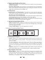
a. Analog Inputs/Outputs
- Inputs: These are 1/4" unbalanced phone jacks which connect to sources such
as the effects sends of mixing console. They may be used with nominal input
level up to 9dBu.
For mono application, use the Left / Mono input. The Left / Mono input jack is
normal to the Right jack. This means that when nothing is plugged into the Right
input jack, the signal present at the Left / Mono input is routed to the Right as
well.
- Outputs: These are 1/4" unbalanced phone jacks which connect to devices
such as the effects returns on a mixing console or power amplifier inputs.
b. Effects Bypass Pedal Input
- Effects Bypass: This is a 1/4" phone jack which connects to a footswitch (with
latching), either normally-open or normally-closed. When the footswitch is in
the state of "OFF", the function will be "Effects"; On the other hand, when the
footswitch is in the state of "ON", the effect will be disabled.
7
c. Power Connector
- Power connector: This is a plug for connecting the 9VAC power supply adaptor
provided by the manufacturer.
4. Installation & Connection
4.1 Audio Connections and Power Up
a. Audio Connections
The connections between the Verb and the other audio devices have to be
made using high quality cables so to prevent bad performances of the Verb
itself. So it should be good to use low-capacitance shielded cables with a flexible
internal conductor. Connect the cables to the Verb properly by observing the
following precautions:
Do not bundle audio cables with AC power cords.
Do not place audio cables and Verb, near sources of electromagnetic interference such as transformers, monitors, computers, etc.
Always unplug cables by firmly grasping the body of the plug and pulling directly outward.
Do not place cables where they can be stepped on.
Avoid twisting the cable or having it make sharp, right angle turns.
b. Power Up Setting
After making your connections, turn on the system's power using this procedure:
Before turning on the Verb's power, check if:
All connections have been made correctly.
The volume controls of the amplifier or mixer are turned down.
Insert the Power plug into the POWER input on the rear panel of the Verb and plug
the power adapter into an AC outlet.
Turn on the power of the Verb, pushing the ON/OFF button on the front panel.
Turn on the power of the amplifier/mixer, and adjust the volume.
4.2. Analog
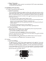
a. Input Jack Wiring
The Verb's [LEFT] INPUT jack is also mono input for the Verb. If you only
connect a single mono cable to the [LEFT] INPUT jack, it will be also routed automatically to the [RIGHT] INPUT. However, if we are using stereo input signals,
connecting a cable to the RIGHT INPUT jack, the automatic routing will be avoided
and the LEFT INPUT jack will feed only the LEFT INPUT, and the RIGHT INPUT
jack will feed only the RIGHT INPUT.
Inputs
Outputs
LEFT/CH 1
LEFT/CH 1
RIGHT/CH 2
LEFT/CH 1
RIGHT/CH 2
LEFT/CH 1
RIGHT/CH 2
8
b. Levels Setting
Proper setting of the input and output levels is crucial in order to achieve the
maximum signal-to-noise ratio. It is possible to say that it is usually best to set
both input and output level controls at 3/4 or 75% of full. This will decrease the
possibility of overload distortion and keep the amount of background noise to a
minimum. If the signal LED on the Verb start lighting, signalling a process saturation, turn down the Input level or decrease the volume of the source (instrument, mixer send, etc.). If the Verb's level is causing the mixer or amp to distort,
turn the Output Level down.
c. Effects Mix Level Adjust
Whether a program contains a single effect or two or three effects, you can adjust the Verb's [MIX] control to obtain a desirable balance between the original
signal and the effect one. Turning [MIX] to the right allows you to hear more Effects; turning it to the left lets you hear more of the source signal. When hooked
up to an instrument setup, such as a guitar amp, the Mix setting will typically
be somewhere in the middle, balancing the effects with the sound of the source
instrument. If the Verb is connected to a mixing console's Aux Send, the [MIX]
control should be set all the way to the right (effects only) so that the balance
can be controlled from the board.
d. Effects Bypass
At any time you can bypass the process, there by allowing the direct signal to
pass through the Verb unchanged. This can be done in two ways:
by turning the MIX knob all the way to the left.
by connecting a footswitch to the [BYPASS] jack and pressing the footswitch.
On the back panel you will find a footswitch jack labelled [BYPASS]. This is a
mono jack with connections for a standard footswitch. The footswitch must be
plugged in before the Verb has its power turned on: Verb will automatically
recognise the right "polarity" of the pedal.
4.3 Installation
a. Standard Use
The Verb may be placed almost anywhere: on a table, on top of an amp, next
to a mixing console. If it will be on furniture, check the rubber feet provided to
the bottom of the unit. Make sure to place the Verb's power supply away from
other audio equipment that may induce fields, and away from the signal wiring.
It is possible that Verb may pick up noise fields generated by other equipment
such as large power amplifiers; in this case, move the Verb until the noise
goes away.
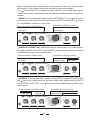
b. Application Examples
- LINE INSTRUMENT
9
When connecting audio cables and/or turning power on and off, make sure that
all devices in your system have their volume controls turned down.
The Verb has two 1/4" unbalanced inputs and two 1/4" unbalanced outputs.
These input/output configuration may provide three different audio connections
options:
MONO. Connect an audio cable to the [LEFT] INPUT of the Verb from a
mono source, and another audio cable from the [LEFT] output of the Verb to
an amplification system or mixer input.
To Amplifier or Mixing Console
From Instrument or Effects Send
Left Input
Left Output
R
LTO
0
10
Verb
24 32 BIT DIGITAL EFFECTS MODULE
0
INPUT
SIGNAL
TM
10
0
MIX
10
Rotary
Chorus/Rev
Flange/Rev
Delay/Rev
Delay
Flange
Chorus
Tremolo
Hall 1
Hall 2
16 1
15
Hall 3
Room 1 14
Room 2 13
Room 3 12
Plate 1
11
10 9
Plate 2
2
3
4
5
6
7
8
ON OFF
POWER
VARIATIONS
OUTPUT
MONO IN, STEREO OUT. While still using a mono input, you could connect
two audio cables to the [LEFT] and [RIGHT] outputs of the Verb to a stereo
amplification system or two mixer inputs.
To Amplifier or Mixing Console
From Instrument or Effects Send
Left Input
Right Output
R
LTO
0
10
Verb
24 32 BIT DIGITAL EFFECTS MODULE
0
INPUT
SIGNAL
TM
10
0
MIX
10
Rotary
Chorus/Rev
Flange/Rev
Delay/Rev
Delay
Flange
Chorus
Tremolo
Hall 1
Hall 2
16 1
15
Hall 3
Room 1 14
Room 2 13
Room 3 12
Plate 1
11
10 9
Plate 2
Left Output
2
3
4
5
6
7
8
ON OFF
POWER
VARIATIONS
OUTPUT
STEREO. Connect two audio cables to the [LEFT] and [RIGHT] INPUTS of
the Verb from a stereo source, and two other audio cables from the [LEFT]
and [ RIGHT] OUTPUTS of the Verb to a stereo amplification system or two
mixer inputs.
To Amplifier or Mixing Console
From Instrument or Effects Send
Right Input
R
LTO
0
SIGNAL
10
INPUT
Right Output
Left Input
Verb
TM
24 32 BIT DIGITAL EFFECTS MODULE
0
10
MIX
0
10
Rotary
Chorus/Rev
Flange/Rev
Delay/Rev
Delay
Flange
Chorus
Tremolo
Left Output
Hall 1
Hall 2
16 1
15
Hall 3
Room 1 14
Room 2 13
Room 3 12
Plate 1
11
10 9
Plate 2
2
3
4
5
6
7
8
VARIATIONS
OUTPUT
10
ON OFF
POWER
- MIXER
Interfacing to a Mixing Console
The Verb can accept mono or stereo sends at all system levels. The input
circuitry of the Verb can easily accept professional +8/9dBu levels while having
enough input and output gain to interface with the low signal levels of home
recording systems.
Aux Send
Aux Return
R
LTO
Verb
TM
24 32 BIT DIGITAL EFFECTS MODULE
MIXING CONSOLE
0
SIGNAL
10
INPUT
0
10
MIX
0
10
OUTPUT
Rotary
Chorus/Rev
Flange/Rev
Delay/Rev
Delay
Flange
Chorus
Tremolo
Hall 1
Hall 2
16 1
15
Hall 3
Room 1 14
Room 2 13
Room 3 12
Plate 1
11
10 9
Plate 2
2
3
4
5
6
7
8
VARIATIONS
ON OFF
POWER
The Verb may be connected to a mixing console in several different ways. It
can be used to with multiple channels at once by using the auxiliary send and
return controls of the mixer. Another way of interfacing is to connect the Verb
directly to the insert send and return of a single channel that is to be effected.
More, Verb could be to connected to a mixer or recording console in-line
between the output of the mixing console and the input of a tape deck or power
amplifier. This last setup would effect the entire mix output.
Using Aux Sends and Returns
Generally, on mixing consoles are available two types of auxiliary sends: prefader sends (headphone or monitor), and post-fader sends for effects units.
Typically, if a mixer has more than two sends per channel (4, 6 or 8, perhaps),
the first two sends are reserved for the pre-fader sends, while the remaining
sends are used to send the signal to be effected to devices as the Verb.
Connect the Verb using post-fader sends, so fading a channel out, its effects
will fade also. Using a mixer's aux sends allows each channel to have its own
level control going to the aux output. It is possible to mix all the channels we
want to be sent to the effects by using the individual channels' aux send levels
on the mixer. Most consoles also have aux master controls, which set the overall level of each aux output. Sending signal to the Verb is only half of the
process. With a mixing console, the output of the Verb must go back to the
mixer and turned up in the mix before to be able to hear it. Depending from the
mixer, there are two options for returning the effected signal to the mix:
connecting to dedicated aux return inputs, or
connecting to channel inputs.
Everything is easy if the mixer provides dedicated inputs (called returns) for
effect devices like the Verb. If the mixer does not have these, or the available
returns have already been used all, it possible to connect the Verb to channel
inputs (if there are any remaining).
11
The effect returns generally should only contain effected signal, and not have
any uneffected or "DRY" signal mixed with it (since these two signals are blended
together at the mixer).
Therefore, it is necessary to set the mix so that only effected ("WET") signal is
present at the Verb's outputs. To do this, turn the Mix control all the way to the
right.
Mono in - stereo out.
If you only want to use the Verb for a mono input signal and to connect both
of its outputs back to the mixer, you will need three audio cables. Connect an
audio cable from an effect send to the LEFT input of the Verb, another 2 audio cable from the LEFT and RIGHT outputs of the Verb to a couple of effect
return or other mixer inputs. On the reverb effect Verb creates a stereo output,
even though only a single input is used.
Stereo in - stereo out.
This connection is similar to the one described above. However, by utilizing two
sends from the mixer, we have to use one more audio cable to send a stereo
signal to the Verb's inputs. The use of a stereo input is especially useful on
the true stereo reverb program.
How to Set Aux Send and Return Levels on the Mixer.
In the above connections, it is necessary to set proper levels on the mixer's
individual Aux Sends, Aux Masters, and Aux Return masters (as well as the
Verb 's own controls) to get good, clean, quiet results.
Improper level setting is the most common cause of noise and distortion problems.
By having the correct level at every point in the send/return chain, it is possible
to avoid overloading distortion and minimize noise. The most common mistake
using effect units like the Verb is to have too low the input signal level and
to increase too much the output level to compensate the input and reach the
desired effects level: this amplifies the noise reducing headroom. Here is a
procedure that will give good results with most standard equipment:
1. Set your mixer's input levels correctly.
2. Turn up the mixer channels' AUX SEND and AUX MASTERS (if applicable)
to a nominal level (this is usually between "noon" and "3:00" on a rotary knob).
3. Play the source.
4. Turn up the Verb's [INPUT] level until you see the [SIGNAL] LED start lighting on peaks; then reduce it slightly until the led stops lighting. The ideal
input level, to minimize the noise, is just below the clipping level. But if other
instruments will be added to the mix later, or levels are unpredictable (as in
a live show), it's preferable to leave additional headroom by turning the input
level down a bit more.
12
5. Depending on the input sensitivity of the mixer's channels or Aux Returns,
the [OUTPUT] knob of the Verb should be set somewhere between "2:00"
and fully clockwise ("5:00").
6. Turn up the AUX RETURN level until desired level of effect in the mix is reached. The control in the chain that may need to be set to a low level is the
Aux Return on the mixer itself. Here is where should increase or decrease
the overall effect level in the mix to minimize the noise.
4.4 Rack Mounting
The most secure mounting is on an "universal" rack shelf, available from various
rack manufacturers or music dealer. Up to two Verb's may be mounted side-byside in a standard universal EIA 19" equipment rack.
R
LTO
0
SIGNAL
10
INPUT
Verb
TM
24 32 BIT DIGITAL EFFECTS MODULE
0
10
MIX
0
10
Rotary
Chorus/Rev
Flange/Rev
Delay/Rev
Delay
Flange
Chorus
Tremolo
R
Hall 1
Hall 2
16 1
15
Hall 3
Room 1 14
Room 2 13
Room 3 12
Plate 1
11
10 9
Plate 2
LTO
TM
24 32 BIT DIGITAL EFFECTS MODULE
3
4
5
6
7
0
8
10
0
10
0
10
ON OFF
VARIATIONS
OUTPUT
Verb
2
POWER
SIGNAL
INPUT
MIX
Hall 1
Hall 2
16 1
15
Hall 3
Room 1 14
Room 2 13
Room 3 12
Plate 1
11
10 9
Plate 2
Rotary
Chorus/Rev
Flange/Rev
Delay/Rev
Delay
Flange
Chorus
Tremolo
2
3
4
5
6
7
8
VARIATIONS
OUTPUT
ON OFF
POWER
5. Preset Functions Descriptions
5.1 Reverbs
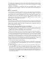
Reverb in nature, is the sum of a large number of distinct echoes generated by the
reflection of the original sound against obstacles (i.e. walls). In a real acoustic space,
the amplitude and brightness of these reflections decay over time and the decaying
is depending on the room size, the position of the sound source acoustic space, the
"nature" of obstacles (shape, material, dimension, etc.), and many other factors.
Impulse Response
Early
Reflections
Late Reflections
time
a. Halls
This algorithm is the simulation of a large acoustic space (as a concert hall).
Halls want to simulate large rooms with many reflective surfaces, where sounds
can be reflected and also hided, changing its "colour" over time. This is a classic
reverb and can be used with all sound sources as vocals, drums or acoustic and
electric instruments.
Hall 1 - This is a large bright hall program with 54ms predelay, and can be used
for almost anything.
13
Hall 2 - This is a warmer hall program with 77ms predelay, and adds depth and
character to acoustic instruments.
Hall 3 - The third program is a medium bright hall with no predelay, and can be
used on rock snares and percussions.
b. Rooms
This algorithm try to reproduce the sound of a medium size room. It has a more
dense and rich sound than the hall reverb algorithm, and this quality makes it
good for rock and "disco" music. The attack is well defined and "aggressive",
sounding very good on keyboards, guitars and drums.
Room 1- This program simulate a studio room with many "early reflection", and
works well with drum sounds and acoustic instruments.
Room 2- This program is a "bright" studio room and seems to be perfect for
adding a little ambience to a dry sound as the one achievable with a synth sound.
Room 3- The third room is the warmest one and is perfect for acoustic guitars
and classical instruments
c. Plates
This algorithm want to simulate the "sound" of a classic plate reverb, obtained
in the past using suspended sheet of metal with transducers at either end. This
kind of reverb, commonly used in the 1970's, it is still useful for its transparent
sound and it works well for vocals, piano, or guitar.
Plate 1- The first program is a classic bright vocal plate.
Plate 2- A warmer variation of the previous program, sounding very well on
acoustic guitar and strings.
5.2 Modulations
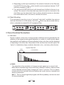
a. Tremolo
Amplitude Multiplier
Modulated by Ramp/Sin LFO
Input
Output
LFO
Tremolo is an amplitude modulation of the signal. It is useful for adding warmth
and life to standing electric piano or guitar's chords.
Tremolo- This program provides an amplitude modulation of the input signal and
is normally used as "WET" effect without adding direct sound or adding a few
percentage of it, so to avoid the direct sound to cover the amplitude modulation.
14
Tremolo Parameters Adjust
Rate - This control sets the amplitude modulation rate.
Sin/Ramp Lfo - From 1 to 8 Ramp, From 9 to 16 Sin
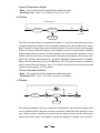
b. Chorus
Analog Input (Direct)
Effect
Input
Fixed Delay
Var Delay Line
Analog Mix
LFO Sin/Ramp
The Chorus effect tries to recreate the illusion of more than one instrument from
a single instrument sound. Two musicians playing the same instrument never
play in perfect unison (both time and pitch wise). In order to build up the proper
illusion using an electronic device, the original sound is summed with a slightly
delayed and detuned version of itself. Instead of a constant pitch deviation, more
natural results come from a varying pitch deviation (two players never keep constant their relative pitch distance). Verb's algorithm implements the variable
delay and the detuning of it is modulated by an LFO (low frequency oscillator)
which causes the detuning to vary. The direct sound and the detuned one are
summed analogically on the outputs.
Chorus Parameters Adjust
Rate - This control sets the amplitude modulation rate.
Sin/Ramp LFO - From 1 to 8 Sin, From 9 to 16 Ramp
c. Flanger
Regeneration %
Effect
Delay
Var Delay Line
Input
Analog Mix
LFO Sin/Ramp
The flanger started its life as a mechanical realization: two identical tapes were
run in parallel while a human operator randomly controlled the speed of each
unit, making minor variations up and down the nominal tape speed. Mixing the
sound from both tapes, the signals sometimes aligned in phase, while other ti-
15
mes aligned in counter phase, resulting in a time-varying filtering that has been
named 'flanger'. The structure of the flanger is then that of the mix of two randomly delayed copies of a signal. Here the detuning process is same as the one
of the chorus, added with a "regeneration" part.
Flanger Parameters Adjust
Rate - This control sets the amplitude modulation rate.
Sin/Ramp LFO - From 1 to 8 Ramp, From 9 to 16 Sin
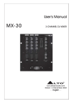
d. Rotary (Speakers)
Amp Mod
LP F
HP F
Cyl %
Var Delay Line
LFO Sin
LFO Sin
LFO Sin
LFO Sin
Var Delay Line
Input
Amp Mod
Horn %
The rotary speaker effect simulates the sound effect achieved by rotating horn
speakers and a bass cylinder, as first produced for organs. The sound is altered
by the Doppler effect, the directional characteristic of the speakers, phase effects
due to air turbulence, etc. The rotary speaker system is normally used with organs,
but can be used also for guitar amplification.
Note: When using the Rotary program, the Mix potentiometer has be turned all
right on "WET" position.
Rotary Parameters Adjust
Rate - This control sets the amplitude modulation rate.
5.3 Delay
Delay effect is a single echo repetition where the repetitions occur after a certain
"delay time" and where the number of repetitions depend on a "decay time", defining
the time necessary to decrease the amplitude of the repetition from the original
sound level to zero.
Delay- This program provides a delay of up to 1000 ms. The delay time can be
adjusted in terms of delay and the decay time depends automatically from the delay
time. This is a useful utility program which can add space to vocals or instruments.
Delay Parameters Adjust
Delay/Decay Time - This control sets the time between the input signal and the
first delay tap and the decay time.
16
5.4 Combined Effects
a. Delay+Reverb - The third multieffects program adds a Room to the different
delay presets.
b. Flanger+Reverb - The first multieffects program is a layered stereo flange and
large room reverb. It works great on guitars, synths and electric pianos.
c. Chorus+Reverb - The second multieffects program is a layered stereo chorus
and large room reverb. Also that one works great on guitars, synths and electric
pianos.
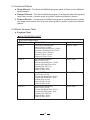
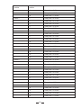
5.5 Effects Summary Table
a. Program Chart
Verb PROGRAM CHART
Verb PROGRAM CHART
PROGRAM NAME
DESCRIPTION
ADJUST CONTROL
HALL 1
HALL REVERB Algorithm
Input LP filter: 16 kHz
Process High Damp Filter: 12 kHz
Process Low Damp Filter: 50 Hz
Predelay Time: 0.054 ms
Output LP filter: 16 kHz
Output HP filter: 50 Hz
DECAY TIME
HALL 2
HALL REVERB Algorithm
Input LP filter: 7 kHz
Process High Damp Filter: 7.5 kHz
Process Low Damp Filter: 50 Hz
Predelay Time: 0.077 ms
Output LP filter: 4 kHz
Output HP filter: 20 Hz
DECAY TIME
HALL 3
HALL REVERB Algorithm
Input LP filter: 12 kHz
Process High Damp Filter: 12 kHz
Process Low Damp Filter: 20 Hz
Predelay Time: 0.0 ms
Output LP filter: 12 kHz
Output HP filter: 20 Hz
DECAY TIME
ROOM 1
ROOM REVERB Algorithm
Input LP filter: 14 kHz
Process High Damp Filter: 12 kHz
Process Low Damp Filter: 20 Hz
Predelay Time: 0.003 ms
Output LP filter: 12 kHz
Output HP filter: 20 Hz
DECAY TIME
17
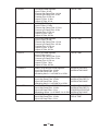
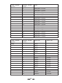
ROOM 2
ROOM REVERB Algorithm
Input LP filter: 16 kHz
Process High Damp Filter: 14 kHz
Process Low Damp Filter: 20 Hz
Predelay Time: 0.003 ms
Output LP filter: 12 kHz
Output HP filter: 20 Hz
DECAY TIME
ROOM 3
ROOM REVERB Algorithm
Input LP filter: 6.5 kHz
Process High Damp Filter: 2.5 kHz
Process Low Damp Filter: 20 Hz
Predelay Time: 0.019 ms
Output LP filter: 6 kHz
Output HP filter: 200 Hz
DECAY TIME
PLATE 1
PLATE REVERB Algorithm
Input LP filter: 12 kHz
Process High Damp Filter: 12 kHz
Process Low Damp Filter: 100 Hz
Predelay Time: 0.019 ms
Output LP filter: 16 kHz
Output HP filter: 200 Hz
DECAY TIME
PLATE 2
PLATE REVERB Algorithm
Input LP filter: 8 kHz
Process High Damp Filter: 5 kHz
Process Low Damp Filter: 50 Hz
Predelay Time: 0.019 ms
Output LP filter: 7 kHz
Output HP filter: 200 Hz
DECAY TIME
TREMOLO
AMPLITUDE MODULATION Algorithm
Input High Damp Filter: 18 kHz
Input Low Damp Filter: 10 Hz
Modulating Waves: 1 to 8 RAMP, 9 to 16 SIN
MODULATION RATE
MODULATING WAVE
CHORUS
PHASE MODULATION Algorithm
Input High Damp Filter: 18 kHz
Input Low Damp Filter: 10 Hz
Modulating Waves: 1 to 8 RAMP, 9 to 16 SIN
MODULATION RATE
MODULATION DEPTH
MODULATING WAVE
FLANGER
PHASE MODULATION with REGENERATION Algorithm
Input High Damp Filter: 18 kHz
Input Low Damp Filter: 10 Hz
Modulating Waves: 1 to 8 RAMP, 9 to 16 SIN
MONO DELAY Algorithm
Input High Damp Filter: 18 kHz
Input Low Damp Filter: 10 Hz
MODULATION RATE
MODULATION DEPTH
REGENERATION PERCENTAGE
MODULATING WAVE
DECAY TIME
DELAY TIME
DELAY
18
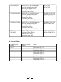
DELAY/REVERB
MONO DELAY + REVERB Algorithm
Input High Damp Filter: 18 kHz
Input Low Damp Filter: 10 Hz
Predelay Time: 0.0 ms
Process LP filter: 12 kHz
DELAY TIME
DECAY TIME
FLANGER/REVERB
MONO DELAY + FLANGE Algorithm
Input High Damp Filter: 18 kHz
Input Low Damp Filter: 10 Hz
Predelay Time: 8 ms
Process LP filter: 12kHz
Modulating Waves: 1 to 8 RAMP, 9 to 16 SIN
REVERB DECAY TIME
REGENERATION PERCENTAGE
MODULATING WAVE
CHORUS/REVERB
MONO DELAY + CHORUS Algorithm
Input High Damp Filter: 18 kHz
Input Low Damp Filter: 10 Hz
Predelay Time: 8 ms
Process LP filter: 12kHz
Modulating Waves: 1 to 8 RAMP, 9 to 16 SIN
REVERB DECAY TIME
MODULATING WAVE
ROTARY
SPEAKERS
STEREO LESLIE Algorithm
Cylinders LP filter: 200 Hz
Horns HP filter: 2 kHz
Modulating Waves: SIN
ROTATION SPEED
MODULATION DEPTH
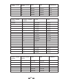
b. Preset Value
Preset encoder
position
Variation encoder
position
Value
Hall 1
1
2
3
4
5
6
7
8
9
Decay time = 0.37 sec.
Decay time = 0.46 sec.
Decay time = 0.56 sec.
Decay time = 0.58 sec.
Decay time = 0.64 sec.
Decay time = 0.75 sec.
Decay time = 0.87 sec.
Decay time = 0.96 sec.
Decay time = 1.21 sec.
19
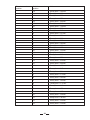
Preset encoder
position
Hall 2
Hall 3
Variation encoder
position
Value
10
11
Decay time = 1.46 sec.
Decay time = 1.90 sec.
12
Decay time = 2.20 sec.
13
Decay time = 3.50 sec.
14
Decay time = 4.40 sec.
15
Decay time = 9.10 sec.
16
1
2
Decay time = > 30 sec.
Decay time = 0.39 sec.
Decay time = 0.49 sec.
3
Decay time = 0.51 sec.
4
5
6
7
8
9
10
Decay time = 0.58 sec.
Decay time = 0.68 sec.
Decay time = 0.80 sec.
Decay time = 0.82 sec.
Decay time = 1.00 sec.
Decay time = 1.22 sec.
Decay time = 1.52 sec.
11
12
Decay time = 2.11 sec.
Decay time = 2.40 sec.
13
Decay time = 3.50 sec.
14
Decay time = 4.30 sec.
15
Decay time = 8.60 sec.
16
Decay time = > 30 sec.
1
Decay time = 0.45 sec.
2
Decay time = 0.61 sec.
3
Decay time = 0.73 sec.
4
Decay time = 0.82 sec.
5
Decay time = 1.02 sec.
6
Decay time = 1.11 sec.
7
Decay time = 1.19 sec.
8
Decay time = 1.50 sec.
9
Decay time = 1.85 sec.
10
Decay time = 2.28 sec.
11
Decay time = 2.80 sec.
12
Decay time = 3.50 sec.
13
Decay time = 5.30 sec.
20
Preset encoder
position
Room 1
Room 2
Variation encoder
position
Value
14
Decay time = 6.40 sec.
15
Decay time = 13.90 sec.
16
Decay time = > 40 sec.
1
Decay time = 0.32 sec.
2
Decay time = 0.37 sec.
3
Decay time = 0.43 sec.
4
Decay time = 0.46 sec.
5
Decay time = 0.55 sec.
6
Decay time = 0.64 sec.
7
Decay time = 0.68 sec.
8
Decay time = 0.79 sec.
9
Decay time = 0.99 sec.
10
Decay time = 1.28 sec.
11
Decay time = 1.68 sec.
12
Decay time = 1.90 sec.
13
Decay time = 2.90 sec.
14
Decay time = 3.60 sec.
15
Decay time = 6.90 sec.
16
Decay time = > 25 sec.
1
Decay time = 0.36 sec.
2
Decay time = 0.43 sec.
3
Decay time = 0.44 sec.
4
Decay time = 0.50 sec.
5
Decay time = 0.54 sec.
6
Decay time = 0.59 sec.
7
Decay time = 0.75 sec.
8
Decay time = 0.89 sec.
9
Decay time = 1.07 sec.
10
Decay time = 1.33 sec.
11
Decay time = 1.84 sec.
12
Decay time = 2.00 sec.
13
Decay time = 3.00 sec.
14
Decay time = 3.60 sec.
15
Decay time = 7.50 sec.
21
Preset encoder
position
Room 3
Plate 1
Plate 2
Variation encoder
position
Value
16
Decay time = > 25 sec.
1
Decay time = 0.35 sec.
2
Decay time = 0.38 sec.
3
Decay time = 0.41 sec.
4
Decay time = 0.47 sec.
5
Decay time = 0.52 sec.
6
Decay time = 0.62 sec.
7
Decay time = 0.73 sec.
8
Decay time = 0.87 sec.
9
Decay time = 1.07 sec.
10
Decay time = 1.30 sec.
11
Decay time = 1.65 sec.
12
Decay time = 1.80 sec.
13
Decay time = 2.80 sec.
14
Decay time = 3.40 sec.
15
Decay time = 6.30 sec.
16
Decay time = > 25 sec.
1
Decay time = 0.42 sec.
2
Decay time = 0.49 sec.
3
Decay time = 0.63 sec.
4
Decay time = 0.64 sec.
5
Decay time = 0.73 sec.
6
Decay time = 0.85 sec.
7
Decay time = 0.96 sec.
8
Decay time = 1.09 sec.
9
Decay time = 1.45 sec.
10
Decay time = 1.65 sec.
11
Decay time = 2.18 sec.
12
Decay time = 2.50 sec.
13
Decay time = 3.90 sec.
14
Decay time = 4.90 sec.
15
Decay time = 9.10 sec.
16
Decay time = > 30 sec.
1
Decay time = 0.44 sec.
22
Preset encoder
position
Preset encoder
position
Delay
Variation encoder
position
Value
2
Decay time = 0.51 sec.
3
Decay time = 0.56 sec.
4
Decay time = 0.64 sec.
5
Decay time = 0.67 sec.
6
Decay time = 0.81 sec.
7
Decay time = 0.96 sec.
8
Decay time = 1.07 sec.
9
Decay time = 1.39 sec.
10
Decay time = 1.61 sec.
11
Decay time = 2.13 sec.
12
Decay time = 2.40 sec.
13
Decay time = 3.70 sec.
14
Decay time = 4.80 sec.
15
Decay time = 8.50 sec.
16
Decay time = > 30 sec.
Variation encoder
position
Delay Time
Decay Time
1
30 ms
-
2
40 ms
-
3
50 ms
-
4
60 ms
-
5
70 ms
-
6
80 ms
-
7
100 ms
1.00 sec.
8
200 ms
1.90 sec.
9
300 ms
3.30 sec.
10
400 ms
4.00 sec.
11
500 ms
4.30 sec.
12
600 ms
5.30 sec.
13
700 ms
6.30 sec.
14
800 ms
7.00 sec.
15
900 ms
8.00 sec.
16
1000 ms
10.00 sec.
23
Preset encoder
position
Variation encoder Delay Time
position
Delay+Rev
Delay Decay Time Rev. Decay Time
1
30 ms
-
1.30 sec.
2
40 ms
-
1.30 sec.
3
50 ms
-
1.30 sec.
4
60 ms
-
1.40 sec.
5
80 ms
0.75 sec.
1.30 sec.
6
100 ms
1.40 sec.
2.30 sec.
7
200 ms
2.40 sec.
3.00 sec.
8
300 ms
3.40 sec.
3.30 sec.
9
400 ms
3.30 sec.
4.00 sec.
10
500 ms
4.00 sec.
4.40 sec.
11
600 ms
4.40 sec.
6.00 sec.
12
700 ms
5.00 sec.
7.30 sec.
13
800 ms
6.00 sec.
7.40 sec.
14
900 ms
7.20 sec.
8.00 sec.
15
1000 ms
8.20 sec.
8.30 sec.
16
1200 ms
9.00 sec.
9.30 sec.
Preset encoder
position
Variation encoder Period
position
Rate
Tremolo
1
840 ms
1.19 Hz
84 %
2
600 ms
1.60 Hz
84 %
3
380 ms
2.63 Hz
84 %
4
260 ms
3.84 Hz
84 %
5
200 ms
5.00 Hz
84 %
6
130 ms
7.69 Hz
84 %
7
100 ms
10.00 Hz
84 %
8
60 ms
16.00 Hz
84 %
9
1400 ms
0.71 Hz
36 %
10
840 ms
1.19 Hz
36 %
11
650 ms
1.56 Hz
36 %
12
470 ms
2.12 Hz
36 %
24
Amplitude Att.
Preset encoder
position
Variation encoder Period
position
Rate
Amplitude Att.
13
400 ms
2.50 Hz
36 %
14
320 ms
3.12 Hz
36 %
15
260 ms
3.84 Hz
36 %
16
200 ms
5.00 Hz
36 %
Preset encoder
position
Variation encoder
position
Period
Rate
Chorus
1
11.00 sec.
0.09 Hz
2
4.80 sec.
0.21 Hz
3
3.20 sec.
0.31 Hz
4
1.78 sec.
0.56 Hz
5
1.20 sec.
0.83 Hz
6
1.09 sec.
0.91 Hz
7
0.75 sec.
1.30 Hz
8
0.41 sec.
2.43 Hz
9
12.80 sec.
10
9.20 sec.
0.11 Hz
0.07 Hz
11
1.06 sec.
0.94 Hz
12
0.62 sec.
1.61 Hz
13
0.47 sec.
2.13 Hz
14
0.56 sec.
1.78 Hz
15
0.40 sec.
2.50 Hz
16
0.30 sec.
3.33 Hz
Preset encoder
position
Variation encoder Period
position
Rate
Feedback %
Flanger
1
13.4 sec.
0.075 Hz
67
2
13.4 sec.
0.075 Hz
75
3
13.4 sec.
0.075 Hz
82
4
6.05 sec.
0.165 Hz
60
5
6.05 sec.
0.165 Hz
72
6
6.05 sec.
0.165 Hz
82
25
Preset encoder
position
Variation encoder Period
position
Rate
Feedback %
7
6.05 sec.
0.165 Hz
89
8
6.05 sec.
0.165 Hz
92
9
4.50 sec.
0.222 Hz
82
10
3.00 sec.
0.333 Hz
82
11
1.75 sec.
0.571 Hz
82
12
1.30 sec.
0.769 Hz
82
13
1.00 sec.
1.000 Hz
82
14
0.75 sec.
1.333 Hz
82
15
0.70 sec.
1.428 Hz
82
16
0.53 sec.
1.886 Hz
82
Preset encoder
position
Variation encoder Chorus Period
position
Chorus Rate
Rev. Decay Time
Chorus + Rev.
1
1.30 sec.
0.769 Hz
0.78 sec.
2
1.30 sec.
0.769 Hz
1.30 sec.
3
1.30 sec.
0.769 Hz
1.75 sec.
4
1.30 sec.
0.769 Hz
2.20 sec.
5
1.30 sec.
0.769 Hz
3.00 sec.
6
1.30 sec.
0.769 Hz
4.00 sec.
7
1.30 sec.
0.769 Hz
5.20 sec.
8
1.30 sec.
0.769 Hz
8.00 sec.
9
1.60 sec.
0.625 Hz
0.78 sec.
10
1.60 sec.
0.625 Hz
1.30 sec.
11
1.60 sec.
0.625 Hz
1.75 sec.
12
1.60 sec.
0.625 Hz
2.20 sec.
13
1.60 sec.
0.625 Hz
3.00 sec.
14
1.60 sec.
0.625 Hz
4.00 sec.
15
1.60 sec.
0.625 Hz
5.20 sec.
16
1.60 sec.
0.625 Hz
8.00 sec.
26
Preset encoder
position
Flanger + Rev.
Variation encoder Flanger Period
position
Flanger Rate
Rev. Decay Time
1
2.00 sec.
0.500 Hz
0.80 sec.
2
2.00 sec.
0.500 Hz
1.30 sec.
3
2.00 sec.
0.500 Hz
1.75 sec.
4
2.00 sec.
0.500 Hz
2.20 sec.
5
2.00 sec.
0.500 Hz
3.00 sec.
6
2.00 sec.
0.500 Hz
3.60 sec.
7
2.00 sec.
0.500 Hz
4.20 sec.
8
2.00 sec.
0.500 Hz
6.40 sec.
9
2.60 sec.
0.384 Hz
0.80 sec.
10
2.60 sec.
0.384 Hz
1.30 sec.
11
2.60 sec.
0.384 Hz
1.75 sec.
12
2.60 sec.
0.384 Hz
2.20 sec.
13
2.60 sec.
0.384 Hz
3.00 sec.
14
2.60 sec.
0.384 Hz
3.60 sec.
15
2.60 sec.
0.384 Hz
4.20 sec.
16
2.60 sec.
0.384 Hz
6.40 sec.
27
28
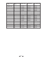
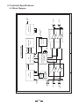
A
B
C
D
INPUT L
(MONO INPUT)
INPUT R
FOOT
SWITCH
1
PJ2
PJ1
PJ5
FOOTSWITCH
CONTROL
1
INPUT LEVEL
INPUT LEVEL
INPUT BUFFER & AMPLIFIER
ENCODER A
VARIATIONS
ENCODER A
PROGRAM
2
IN-R IN-L OUT-R OUT-L
STEREO AUDIO CODEC
A/D and D/A CONVERTER
(U6 PCM3001E)
SO0
(U8 TMS57002DPHA)
(U9 P87C54UBAA)
SI0
DSP
AD0-AD7
3
3
LRCKIN=43.20KHZ
3
BCK=1. 82MHZ
+5V
-5V
OUTPUT LEVEL
OUTPUT LEVEL
PJ4
PJ3
VOLTAGE REGULATOR
POWER SUPPLY
OUTPUT AMPLIFIER
(U7 74HC393)
CLOCK DIVIDE
(U10,U11)
MEMORY(DRAM)
MIX CONTROL
Q1
11.0592MHZ
11.0592MHZ
EA0-EA9
ED0-ED7
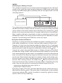
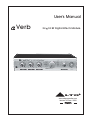
Verb BLOCK DIAGRAM
MPU
2
AC 9V
INPUT
4
OUTPUT L
OUTPUT R
4
A
B
C
D
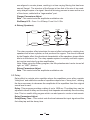
6. Technical Specifications
6.1 Block Diagram
6.2 Specifications
Electrical
Frequency Response:
+0.5 / -1.5 dB from 20Hz to 20 kHz
S/N Ratio (process)
80 dB "A" wtg, 20 Hz-22kHz
S/N Ratio (bypass)
>90 dB "A" wtg, 20 Hz-22kHz
THD+Noise:
<0.008% @ 1kHz (0dBV, bypass)
Input
Number of Channels:
2
Format:
1/4" unbalanced
Maximum Level (bypass):
+9 dBu
Impedance:
>500 Kohms
A/D - D/A Conversions
A/D converter:
1 bit Sigma-Delta
D/A converter:
1 bit Sigma-Delta
Output
Number of Channels:
2
Format:
1/4" unbalanced
Maximum Level (bypass):
+9 dBu
Output Impedance:
<500 ohms
Front Panel
Controls
IN/OUT levels (ANALOG)
PROGRAM selections (2 knobs)
Indicators
Power, Signal clip LED
Rear Panel
Input (LEFT/MONO, RIGHT)
1/4" 2-conductor (mono)
Output (LEFT, RIGHT)
1/4" 2-conductor (mono)
BYPASS
1/4" 2-conductor (auto-sense pedal type)
for momentary footswitches
9 Volt AC Power Transformer
Power
29
Processing and Memory
Processor Speed:
12 MIPs (million instructions per second)
Internal DSP resolution:
52 bit MPY accumulator
Main Preset Programs
16
Preset Total Combinations
256
Internal digital audio memory:
3000 milliseconds
Physical
Net Weight:
1kg(2.20lb)
Dimension:
200(W) 150(D) 45(H)mm
(7.87"
5.91" 1.77")
30
7. Warranty
1. WARRANTY REGISTRATION CARD
To obtain Warranty Service, the buyer should first fill out and return the enclosed Warranty
Registration Card within 10 days of the Purchase Date.
All the information presented in this Warranty Registration Card gives the manufacturer a
better understanding of the sales status, so as to purport a more effective and efficient
after-sales warranty service.
Please fill out all the information carefully and genuinely, miswriting or absence of this
card will void any of your warranty service.
2. RETURN NOTICE
2.1 In case of return for any warranty service, please make sure that the product is well
packed in its original shipping carton, and it can protect your unit from any other extra
damage.
2.2 Please provide a copy of your sales receipt or other proof of purchase with the returned
machine, and give detail information about your return address and contact telephone
number.
2.3 A brief description of the defect will be appreciated.
2.4 Please prepay all the costs involved in the return shipping, handling and insurance.
3. TERMS AND CONDITIONS
3.1
LTO warrants that this product will be free from any defects in materials and/or workmanship for a period of 1 year from the purchase date if you have completed the Warranty
Registration Card in time.
3.2 The warranty service is only available to the original consumer, who purchased this
product directly from the retail dealer, and it can not be transferred.
3.3 During the warranty service, LTO may repair or replace this product at its own option
at no charge to you for parts or for labor in accordance with the right side of this limited
warranty.
3.4 This warranty does not apply to the damages to this product that occurred as the following
conditions:
Instead of operating in accordance with the user's manual thoroughly, any abuse or misuse
of this product.
Normal tear and wear
The product has been altered or modified in any way .
Damage which may have been caused either directly or indirectly by another product/
force/etc.
Abnormal service or repairing by anyone other than the qualified personnel or technician.
And in such cases, all the expenses will be charged to the buyer.
31
3.5 In no event shall LTO be liable for any incidental or consequential damages. Some
states do not allow the exclusion or limitation of incidental or consequential damages,
so the above exclusion or limitation may not apply to you.
3.6 This warranty gives you the specific rights, and these rights are compatible with the state
laws, you may also have other statutory rights that may vary from state to state.
32
SEIKAKU TECHNICAL GROUP LIMITED
No. 1, Lane 17, Sec. 2, Han Shi W. Road, Taichung, 401 Taiwan
http://www.altomobile.com Tel: 886-4-22313737
email: [email protected] Fax: 886-4-22346757
All rights reserved to ALTO Mobile. Due to continued development in response to
customer feedback, product features, specifications and/or internal/external design may be
changed without prior notice. No photocopying, translation or reproduction of any part of this user
manual is allowed without prior written permission.Copyright c 2004 Seikaku Technical Group Limited.
NF00122-1.0