1
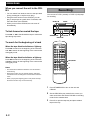
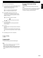
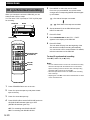
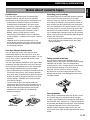
UCAB
KX-M5
Cassette Deck
Platine Cassette
OWNER’S MANUAL
MODE D’EMPLOI
SAFETY INSTRUCTIONS
6A
CAUTION
RISK OF ELECTRIC SHOCK
DO NOT OPEN
7
CAUTION: TO REDUCE THE RISK OF
ELECTRIC SHOCK, DO NOT REMOVE
COVER (OR BACK). NO USER-SERVICEABLE
PARTS INSIDE. REFER SERVICING TO
QUALIFIED SERVICE PERSONNEL.
8
• Explanation of Graphical Symbols
The lightning flash with arrowhead symbol,
within an equilateral triangle, is intended to
alert you to the presence of uninsulated
“dangerous voltage” within the product’s
enclosure that may be of sufficient magnitude
to constitute a risk of electric shock to
persons.
The exclamation point within an equilateral
triangle is intended to alert you to the
presence of important operating and
maintenance (servicing) instructions in the
literature accompanying the appliance.
WARNING
TO REDUCE THE RISK OF FIRE OR ELECTRIC
SHOCK, DO NOT EXPOSE THIS UNIT TO RAIN OR
MOISTURE.
9
10
11
12
13
IMPORTANT!
Please record the serial number of this unit in the
space below.
14
Model:
Serial No.:
15
The serial number is located on the rear of the unit.
Retain this Owner’s Manual in a safe place for future
reference.
1
2
3
4
5
6
Read Instructions – All the safety and operating
instructions should be read before the unit is
operated.
Retain Instructions – The safety and operating
instructions should be retained for future reference.
Heed Warnings – All warnings on the unit and in the
operating instructions should be adhered to.
Follow Instructions – All operating and other
instructions should be followed.
Water and Moisture – The unit should not be used
near water – for example, near a bathtub, washbowl,
kitchen sink, laundry tub, in a wet basement, or near a
swimming pool, etc.
Carts and Stands – The unit should be used only with
a cart or stand that is recommended by the
manufacturer.
2
16
17
18
A unit and cart combination should be
moved with care. Quick stops,
excessive force, and uneven surfaces
may cause the unit and cart
combination to overturn.
Wall or Ceiling Mounting – The unit
should be mounted to a wall or ceiling only as
recommended by the manufacturer.
Ventilation – The unit should be situated so that its
location or position does not interfere with its proper
ventilation. For example, the unit should not be
situated on a bed, sofa, rug, or similar surface, that
may block the ventilation openings; or placed in a
built-in installation, such as a bookcase or cabinet that
may impede the flow of air through the ventilation
openings.
Heat – The unit should be situated away from heat
sources such as radiators, stoves, or other appliances
that produce heat.
Power Sources – The unit should be connected to a
power supply only of the type described in the
operating instructions or as marked on the unit.
Power-Cord Protection – Power-supply cords should
be routed so that they are not likely to be walked on or
pinched by items placed upon or against them, paying
particular attention to cords at plugs, convenience
receptacles, and the point where they exit from the
unit.
Cleaning – The unit should be cleaned only as
recommended by the manufacturer.
Nonuse Periods – The power cord of the unit should
be unplugged from the outlet when left unused for a
long period of time.
Object and Liquid Entry – Care should be taken so
that objects do not fall into and liquids are not spilled
into the inside of the unit.
Damage Requiring Service – The unit should be
serviced by qualified service personnel when:
A. The power-supply cord or the plug has been
damaged; or
B. Objects have fallen, or liquid has been spilled into
the unit; or
C. The unit has been exposed to rain; or
D. The unit does not appear to operate normally or
exhibits a marked change in performance; or
E. The unit has been dropped, or the cabinet
damaged.
Servicing – The user should not attempt to service the
unit beyond those means described in the operating
instructions. All other servicing should be referred to
qualified service personnel.
Power Lines – An outdoor antenna should be located
away from power lines.
Grounding or Polarization – Precautions should be
taken so that the grounding or polarization is not
defeated.
FCC INFORMATION (for US customers only)
Compliance with FCC regulations does not guarantee
that interference will not occur in all installations. If this
product is found to be the source of interference, which
can be determined by turning the unit “OFF” and “ON”,
please try to eliminate the problem by using one of the
following measures:
Relocate either this product or the device that is being
affected by the interference.
Utilize power outlets that are on different branch (circuit
breaker or fuse) circuits or install AC line filter/s.
In the case of radio or TV interference, relocate/reorient
the antenna. If the antenna lead-in is 300 ohm ribbon
lead, change the lead-in to coaxial type cable.
If these corrective measures do not produce satisfactory
results, please contact the local retailer authorized to
distribute this type of product. If you can not locate the
appropriate retailer, please contact Yamaha Electronics
Corp., U.S.A. 6660 Orangethorpe Ave, Buena Park, CA
90620.
The above statements apply ONLY to those products
distributed by Yamaha Corporation of America or its
subsidiaries.
We Want You Listening For A Lifetime
YAMAHA and the Electronic Industries Association’s Consumer Electronics Group want you to get the
most out of your equipment by playing it at a safe level. One that lets the sound come through loud and
clear without annoying blaring or distortion – and, most importantly, without affecting your sensitive
hearing. Since hearing damage from loud sounds is often undetectable until it is too late, YAMAHA and
the Electronic Industries Association’s Consumer Electronics Group recommend you to avoid prolonged
exposure from excessive volume levels.
For U.K. customers
If the socket outlets in the home are not suitable for the
plug supplied with this appliance, it should be cut off
and an appropriate 3 pin plug fitted. For details, refer to
the instructions described below.
Note: The plug severed from the mains lead must be
destroyed, as a plug with bared flexible cord is hazardous
if engaged in a live socket outlet.
SPECIAL INSTRUCTIONS FOR U.K.
MODEL
IMPORTANT:
The wire in the mains lead are coloured in accordance with the following code:
Blue: NEUTRAL
Brown: LIVE
As the colours of the wires in the mains lead of this
apparatus may not correspond with the coloured
markings identifying the terminals in your plug,
proceed as follows: The wire which is coloured
BLUE must be connected to the terminal which is
marked with the letter N or coloured BLACK. The
wire which is coloured BROWN must be connected
to the terminal which is marked with the letter L or
coloured RED. Making sure that neither core is
connected to the earth terminal of the three pin
plug.
3
English
1. IMPORTANT NOTICE: DO NOT MODIFY THIS UNIT!
This product, when installed as indicated in the
instructions contained in this manual, meets FCC
requirements. Modifications not expressly approved by
Yamaha may void your authority, granted by the FCC,
to use the product.
2. IMPORTANT: When connecting this product to
accessories and/or another product use only high
quality shielded cables. Cable/s supplied with this
product MUST be used. Follow all installation
instructions. Failure to follow instructions could void
your FCC authorization to use this product in the USA.
3. NOTE: This product has been tested and found to
comply with the requirements listed in FCC
Regulations, Part 15 for Class “B” digital devices.
Compliance with these requirements provides a
reasonable level of assurance that your use of this
product in a residential environment will not result in
harmful interference with other electronic devices.
This equipment generates/uses radio frequencies and,
if not installed and used according to the instructions
found in the users manual, may cause interference
harmful to the operation of other electronic devices.
ENGLISH
INTRODUCTION
Thank you for purchasing this YAMAHA product. We hope it will give you many years of trouble-free enjoyment. For
the best performance, read this manual carefully. It will guide you in operating your YAMAHA product.
FEATURES
• High Quality Hard Permalloy Recording/
Playback Head
• Dolby B Noise Reduction
• Recording Mute Function
• Auto Reverse Play
• Rec Reverse function
When you connect the unit to CRX-M5
• Remote control Capability
• Automatic Synchronized Recording
• Timer Play
• Sleep Timer
• Recording Using Timer
“DOLBY” and the double-D symbol
are trademarks
of Dolby Laboratories Licensing Corporation.
Dolby noise reduction manufactured under license
from Dolby Laboratories Licensing Corporation.
Getting
Playing
Started
CDs
SUPPLIED ACCESSORIES
• Audio connecting cords
• System cable
CONTENTS
PRECAUTIONS ..................................................
IDENTIFICATION OF COMPONENT
Front panel ......................................................
Rear panel ......................................................
GETTING STARTED
Connecting the unit to the CRX-M5 ................
Using the remote control transmitter
of the CRX-M5 ................................................
Turning on/off the unit .....................................
E-2
3
4
4
5
6
6
OPERATIONS
Playback .......................................................... 7
Recording ........................................................ 8
CD synchronized recording ........................... 10
ADDITIONAL INFORMATION
Notes about cassette tapes .......................... 11
Maintenance ................................................. 12
Troubleshooting ............................................. 12
Specifications ................................................ 13
PRECAUTIONS: READ THIS BEFORE OPERATING THE UNIT
•
Never allow metallic items (e. g. screwdrivers, tools,
etc,) to come near the record/playback head
assembly. Doing so may not only scratch or
damage the head’s mirror-smooth finish, but also
change the magnetic characteristics of the heads,
causing a deterioration in reproduction quality.
•
Although the record/playback head used in this unit
is a high quality head with outstanding
reproduction characteristics, it can become dirty
through the use of old tapes or from dust
accumulation over time.
This can have a serious effect on reproduction
quality.
Clean the heads regularly with one of the
commonly available head cleaners or with cleaning
solutions as explained later in this manual.
manual carefully. Keep it in a safe place for future
reference.
•
Install your unit in good ventilation, a cool, dry,
clean place – away from windows, heat sources,
vibration, dust, moisture, or cold. To avoid humming
sounds, locate the unit away from other electrical
appliances, motors, and transformers. To prevent
fire or electrical shock, do not expose to rain and
water.
•
Do not operate the unit upside-down. It may
overheat, possibly causing damage.
•
Never open the cabinet. If something drops into the
set, contact your dealer.
•
•
Do not use force on switches, knobs or cords.
When not planning to use this unit for long periods
of time (i.e.., vacation, etc.), disconnect the AC
power plug from the wall outlet.
•
Grounding or polarization – Precautions should be
taken so that the grounding or polarization of the
unit is not defeated.
•
Do not clean the unit with chemical solvents; this
might damage the finish. Use a clean, dry cloth.
•
Be sure to read the “TROUBLESHOOTING”
section on common operating errors before
concluding that your unit is faulty.
•
Do not place another component on top of this unit,
as damage or discoloration on the surface of the
unit may result.
•
To prevent damage by lightning, disconnect the
power cord from the wall outlet during an electrical
storm.
•
When disconnecting the power cord from the wall
outlet, grasp the plug; do not pull the cord.
•
Do not plug the AC power plug to the wall outlet
before you finish all connections.
•
The voltage to be used must be the same as that
specified on this unit. Using this unit with a higher
voltage than that which is specified is dangerous
and may result in a fire or other type of accident
causing damage. YAMAHA will not be held
responsible for any damage resulting from use of
this unit with a voltage other than that which is
specified.
•
Keep this manual in a safe place for future
reference.
WARNING
To reduce the risk of fire or electric shock, do not
expose this appliance to rain or moisture.
To avoid electrical shock, do not open the cabinet.
Refer servicing to qualified personnel only.
This unit is not disconnected from the AC power
source as long as it is connected to the wall outlet,
even if this unit itself is turned off. This state is called
the standby mode. In this state, this unit is designed
to consume a very small quantity of power.
FOR CANADIAN CUSTOMERS
TO PREVENT ELECTRIC SHOCK, MATCH WIDE
BLADE OF PLUG TO WIDE SLOT AND FULLY
INSERT.
THIS CLASS B DIGITAL APPARATUS COMPLIES
WITH CANADIAN ICES-003.
NOTE
Please check the copyright laws in your country to
record from records, compact discs, radio, etc.
Recording of copyright material may infringe
copyright laws.
E-3
English
CAUTIONS
• To assure the finest performance, please read this
IDENTIFICATION OF COMPONENT
FRONT PANEL
STANDBY/ON
DOLBY
NR
REC
MUTE
MODE
REC/
PAUSE
1 STANDBY/ON switch (6)
9 ) (eject) button (7)
2 DOLBY NR indicator (7)
! DOLBY NR button (7)
3 MODE indicators (7)
" MODE switch (7)
4 REC MUTE button (9)
# REC/PAUSE button (9)
5 REC indicator (9)
$ 2 (reverse play) button (7)
6 Cassette tape tray (7)
% 7 (stop) button (7)
7 1/¡ (search) buttons (8)
& 3 (forward play) button (7)
8 Playback direction indicators (7)
REAR PANEL
LINE
OUT
LINE
IN
A
B
L
SYSTEM
CONNECTOR
VOLTAGE
SELECTOR
115 V
230 V
R
1 LINE OUT jacks (5)
2 LINE IN jacks (5)
3 AC power cord (5)
4 SYSTEM CONNECTOR jack (5)
5 VOLTAGE SELECTOR switch (3) (General
model only)
E-4
(General model)
Playing CDs
GETTING STARTED
English
Connecting the unit to the CRX-M5
Never plug the AC power cord into the wall outlet until all other connections are completed.
Follow the steps as shown below to connect the unit to the CRX-M5 using the supplied cords and accessories.
1
3
1
LINE
OUT
LINE
IN
A
B
L
SYSTEM
CONNECTOR
Connect A to A, and B to B using the audio
connecting cords.
Insert the plugs into the jacks of the same color.
• The two audio connecting cords are the same,
so you can connect A or B using either cord.
R
2
2
3
Connect the unit and the CRX-M5 with the system
cable.
Connect the AC power cord to a wall outlet.
1
C
IN
AUX/MD
OUT
D A
TAPE
IN
OUT
L
R
–
–
L
AM
R
SPEAKERS
MIN. /SPEAKER 8 MIN. /HAUT-PARLEUR
+
GND
75
UNBAL
L
R
8
FM
B
SUBWOOFER
ANTENNA
DIGITAL OUT
SYSTEM
CONNECTOR
2
+
CD
OUT
OPTICAL
TAPE
MD
E-5
Playing CDs
GETTING STARTED
Using the remote control
transmitter of the CRX-M5
Turning on/off the unit
STANDBY/ON
You can operate the unit with the remote control
transmitter of the CRX-M5 when you connect the unit
and the CRX-M5 with the system cable.
Operating buttons work as follow:
Buttons for operation
of the unit
POWER
TIMER
CLOCK
SET
/
TUNING
TIME
REP
EDIT
FM/AM
ST/MONO
DISC
1
MEMORY
2
3
PRESET
PGM
/
TUNER CD
1
2
3
4
5
9
0
6
7
8
REC/
PAUSE
REC/
MUTE
CD
SYNC
+10
/
TAPE
MD
INPUT
SLEEP
MUTE
3:
To play back
2:
To playback bottom side
7:
To stop playback
1/¡:
To searching, fastforward, and rewind
REC/PAUSE:
To recording
REC MUTE:
To make the nonrecorded portion
VOLUME
–
+
For more details on the remote control transmitter, see
the instructions of the CRX-M5.
E-6
STANDBY/ON
DOLBY
NR
MODE
REC
MUTE
REC/
PAUSE
After connecting the AC power cord to the wall outlet,
press the STANDBY/ON switch on the front panel to
turn on/off the unit. When you turn off the CRX-M5, the
unit turns off automatically as it is connected to the
CRX-M5 with the system cable.
Getting
Playing
Started
CDs
OPERATIONS
4
Press ) to close the tape tray.
5
Press DOLBY NR to set the DOLBY NR* function
to ON (DOLBY NR indicator lights up) or OFF
(DOLBY NR indicator goes out).
You can use any type of tape, TYPE I (normal), TYPE
II (CrO2), or TYPE IV (metal), since the unit
automatically detects the tape type.
OFF: For a tape recorded with DOLBY NR OFF.
ON: For a tape recorded with DOLBY NR ON.
)
MODE
DOLBY NR
6
STANDBY/ON
DOLBY
NR
REC
MUTE
MODE
REC/
PAUSE
2
STANDBY/ON
7 3
Press MODE to select the reverse mode.
Each time you press MODE, the reverse mode
changes and the corresponding MODE indicator
lights up as follows:
: One side of the tape is played back.
: Both sides of the tape are played back.
POWER
TIMER
CLOCK
SET
/
: Both sides of the tape are played back
repeatedly.
TUNING
TIME
REP
FM/AM
ST/MONO
EDIT
DISC
1
MEMORY
2
3
PRESET
PGM
7
/
TUNER CD
1
2
3
4
5
6
7
8
9
0
REC/
PAUSE
REC/
MUTE
CD
SYNC
7
+10
/
TAPE
3
MD
INPUT
SLEEP
MUTE
Press 3 to start play.
Press 2 to play the bottom side.
Selected tape direction indicator lights up.
VOLUME
–
* DOLBY NR (Dolby Noise Reduction) is an extremely
effective method of reducing undesirable background hiss
on tapes. The unit incorporates the DOLBY B NR system.
2
+
To stop play
Press 7.
To eject a tape
Press ) to open the tape tray and remove the tape
from the tray.
1
Press STANDBY/ON to turn on the unit and
CRX-M5.
2
Set the CRX-M5 to cassette deck function mode.
3
Press ) to open the tape tray and place a
recorded tape on the tray.
To adjust the volume level
Use the volume control of the CRX-M5.
With the side you want to play facing up
E-7
English
Playback
OPERATIONS
When you connect the unit to the CRXM5
• You can switch from another source to the tape deck
just by pressing 3 or 2 (One touch play).
• Using the timer function on the CRX-M5, you can
play or stop a tape at a prefer time. For details, refer
the instructions of the CRX-M5.
• When you turn off the CRX-M5, the unit turns off
automatically.
Recording
You can use a TYPE I (normal) or TYPE II (CrO2) tape
for recording.
STANDBY/ON
DOLBY
NR
REC
MUTE
MODE
)
MODE
DOLBY NR
REC/
PAUSE
To fast-forward or rewind the tape
Press ¡ or 1 to fast-forward the tape or rewind the
tape during stop mode.
REC/PAUSE 2
STANDBY/ON
REC MUTE
3
To search for the beginning of a track
When the tape direction indicator 3 lights up
POWER
TIMER
CLOCK
SET
/
Press ¡ to search for the beginning of the next track
and 1 to search for the beginning of the current track
during play mode.
TUNING
TIME
REP
FM/AM
ST/MONO
EDIT
DISC
1
MEMORY
2
3
PRESET
PGM
/
TUNER CD
When the tape direction indicator 2 lights up
Press 1 to search for the beginning of the next track
and ¡ to search for the beginning of the current track
during play mode.
1
2
3
4
5
6
7
8
9
0
REC/
PAUSE
REC/
MUTE
CD
SYNC
REC/PAUSE
+10
/
TAPE
3
MD
Notes
INPUT
E-8
SLEEP
MUTE
VOLUME
–
• The blank interval between selections must be at least 4
seconds long.
• Searching function may not operate properly with tapes
recorded at a low recording level or which have excessive
noise.
• When you play the beginning part or end part of the tape,
the search function may not work correctly.
2
+
1
Press STANDBY/ON to turn on the unit and
CRX-M5.
2
Set the CRX-M5 to play mode for the source you
want record from and set the CRX-M5 to recording
mode for the cassette deck.
3
Press ) to open the tape tray and place a blank
tape on the tray.
Getting
Playing
Started
CDs
OPERATIONS
Press ) to close the tape tray.
5
Press DOLBY NR to set the DOLBY NR function to
ON (DOLBY NR indicator lights up) or OFF
(DOLBY NR indicator goes out).
OFF: For recording with DOLBY NR OFF.
ON: For recording with DOLBY NR ON.
6
To insert a blank space during
recording
Press REC MUTE during recording or Rec/Pause
mode.
A 4 seconds blank interval is automatically recorded on
the tape and then the unit enters Rec/Pause mode.
To resume recording, press REC/PAUSE.
Press MODE to select the reverse mode.
Each time you press MODE, the reverse mode
changes and the corresponding MODE indicator
lights up as follows:
: One side of the tape is recorded.
,
: Both sides of the tape are recorded.
7
Press REC/PAUSE.
The unit stands by for recording and the REC
indicator flashes.
8
Press 3.
Recording starts and the tape direction indicator 3
lights up.
If you want to record starting from the bottom side,
press 2 so that the tape direction indicator 2 lights
up.
9
Start playing on the source component.
To stop recording
Press 7.
To pause recording
Press REC/PAUSE.
To resume recording, press REC/PAUSE again.
Note
• When you want to reduce the hiss noise in low-level highfrequency signals, set DOLBY NR to ON.
• When you record on the bottom side of the tape, the unit
stops recording after complete recording the bottom side of
the tape regardless of the reverse mode setting in step 6
above.
E-9
English
4
OPERATIONS
CD synchronized recording
5
When you connect the unit to the CRX-M5, you can
easily record a CD on a tape.
You can use a TYPE I (normal) or TYPE II (CrO2) tape
for recording.
STANDBY/ON
DOLBY
NR
REC
MUTE
MODE
TIMER
CLOCK
SET
/
TUNING
TIME
REP
FM/AM
ST/MONO
EDIT
DISC
1
MEMORY
2
3
41/¡¢
PRESET
PGM
/
7 (TUNER CD)
TUNER CD
1
2
3
4
5
6
7
8
9
0
REC/
PAUSE
REC/
MUTE
CD
SYNC
6
Set the desired CD in the CRX-M5 and press
INPUT to select CD.
7
Press CD SYNC.
8
Press 41/¡¢ so that “CD → TAPE”
appears in the display of the CRX-M5.
9
Press CD SYNC.
The unit starts CD play from the beginning of the
disc and the unit starts recording automatically.
You can record a CD in various modes. For details,
refer the instructions of the CRX-M5.
To stop CD synchronized recording
Press 7 (TUNER CD) or 7 (TAPE).
CD SYNC
TAPE
7 (TAPE)
MD
SLEEP
MUTE
VOLUME
–
+
INPUT
1
Press STANDBY/ON to turn on the unit .
2
Press ) to open the tape tray and place a blank
tape on the tray.
3
Press ) to close the tape tray.
4
Press DOLBY NR to set the DOLBY NR function to
ON (DOLBY NR indicator lights up) or OFF
(DOLBY NR indicator goes out).
OFF: For recording with DOLBY NR OFF.
ON: For recording with DOLBY NR ON.
E-10
: Both sides of the tape are recorded.
+10
/
INPUT
,
REC/
PAUSE
STANDBY/ON
POWER
: One side of the tape is recorded.
)
MODE
DOLBY NR
Press MODE to select the reverse mode.
Each time you press MODE, the reverse mode
changes and corresponding MODE indicator lights
up as follows:
Notes
• You can edit the tracks on a CD to be recorded so that they
will fit onto the tape with the least amount of unrecorded
space remaining at the end of each side of the tape using
Automatic editing function of the CRX-M5.
• When the tape becomes full in the middle of the recording,
each unit stops.
• Adjusting the VOLUME control of the CRX-M5 has no effect
on the recorded sound.
Getting
Playing
Started
CDs
ADDITIONAL INFORMATION
English
Notes about cassette tapes
Cassette tapes
Protecting your recordings
There are many different types of cassette tapes
available. However, they all conform to standard
specifications so any brand may be used with the unit.
• Classification of Cassette Tapes by Formulation:
Cassette tapes are available in four basic types
depending of their formulation, or type of magnetic
material and manufacturing process. These four
types are commonly known as Normal (TYPE I/
NORM), Chrome (TYPE II/HIGH <CrO2>),
Ferrichrome (TYPE III/HIGH <FeCr>), and Metal
(TYPE IV/METAL) , and they each require a specific
tape deck.
* YAMAHA does not recommend the use of 120
minute length cassettes since the extreme thinness
of the tape makes them susceptible to mechanical
and recording problems.
All cassette tapes are provided with erasure protection
holes to prevent accidental erasure of recorded
contents. There is a small tab covering the hole on
each side of the cassette, and it should be broken off
after recording the tape. Without this tab covering the
hole, it is impossible to record onto that tape. Thus, you
can safely protect a recording for as long as you wish
without fear of accidental erasure. Should you wish to
use a cassette tape protected in this way for recording,
simply covering the hole with adhesive tape will permit
erasure and re-recording.
• When using Chrome or Metal tapes, make sure you
do not cover the hole intended for the Auto Tape
Selector operation.
Auto tape selector detection slots
The unit has a built-in Auto Tape Selector which
automatically adjusts for the proper bias, level, and
equalization according to the tape formulation – all you
have to do is to load a cassette and the Auto Tape
Selector does the rest.
The Auto Tape Selector determines which type of tape
is loaded by sensing detect slots in the top of the tape
shell. Each tape formulation has its own characteristic
hole markings standardized by the tape industry.
• Early model Metal tape formulation cassette shells do
not have the slots for Auto Tape selector operation.
As a result, early model Metal type tapes recorded on
another deck will be played back with the unit at the
Chrome settings. YAMAHA does not recommend
using this kind of tape.
• The unit does not have the required setting for
Ferrichrome tape, since this tape formulation is not
widely used. Should you use a Ferrichrome tape, it
will be recorded and played back at the Normal
settings which will result in an unnatural high
frequency emphasis.
TYPE II
Detector slots
TYPE IV
Detector slots
Taking up slack in the tape
As a precaution against tape entanglement and
damage, remove any slack in the tape before inserting
cassettes into the deck. This is accomplished by
inserting a pencil, pen, or similar object into one of the
spools and gently winding it unit all the slack is
removed. You do not have to wind it too tightly.
Be careful not to touch the tape part itself. It is very
delicate and touching it may damage the tape and its
recorded contents.
Storing cassettes
After putting a cassette tape back into its case, store it
in a location away from exposure to direct sunlight,
humidity, high temperatures, and magnetic fields (away
from television sets, speakers, etc.). High temperatures
and humidity will damage the tape itself, while exposure
to magnetic fields may cause a loss of recorded
material. Avoid touching the tape surface with your
finger, since dirt or finger oil will contaminate the deck’s
heads.
E-11
ADDITIONAL INFORMATION
Maintenance
Internal care
• Dirty heads, capstans, and pinch rollers can cause poor sound and tape jams.
Clean these parts with a commercially available cleaning tape.
• After long use, the deck’s heads and capstans may become magnetized, causing poor sound. Demagnetize these
parts once every 30 hours of playing/recording time by using a commercially available tape head demagnetizer.
Read the demagnetizer’s instructions carefully before use.
Troubleshooting
If the unit fails to operate normally, check the following points to determine whether the fault can be corrected by the
simple measures suggested. If it cannot be corrected, or if the fault is not listed in the SYMPTOM column, disconnect
the power cord and contact your authorized YAMAHA dealer or service center for help. When taking the service, the
CRX-M5 may be needed. For details, contact your authorized YAMAHA dealer or service center.
SYMPTOM
CAUSE
REMEDY
The unit does not work normally.
There is an influence of strong external
noise (lightning, excessive static
electricity, etc.) or a misoperation was
performed while using the unit.
Turn the unit off and disconnect the AC power
from the wall outlet. After about 30 seconds
have passed, connect the power and try again.
Tape does not move during playback
or recording.
Slack tape wrapped around pinch roller.
Take up slack with a pencil before using.
Cannot record
Erasure prevention tab is broken off.
Replace tape or cover erasure prevention hole
with adhesive tape.
Head is dirty.
Clean heads.
Head is dirty.
Clean heads.
Head has become magnetized.
Demagnetize heads with head eraser.
Tape is worn.
Replace the tape.
Poor sound quality.
Tape encoded with DOLBY NR is played
back with the unit’s DOLBY NR OFF.
Set DOLBY NR to ON.
Stereo balance is poor.
Head is dirty.
Clean heads.
Excessive noise.
Head is dirty.
Clean heads.
Head has become magnetized.
Demagnetize heads with head eraser.
Tape is worn.
Replace the tape.
Slack tape coming out of cassette shell.
Take up slack by turning reels with a pencil.
Tape is worn.
Replace the tape.
Endless tape is being used.
Do not use endless tapes.
The CD synchronized recording
function does not works.
System cable is not connected.
Connect the unit and the CRX-M5 with the
system cable firmly.
Cannot search for the beginning of
desired track of the tape.
Silent gaps between tracks are too short.
The function of searching for the beginning of a
desired track does not operate unless the silent
gaps between tracks are at least four seconds
long.
Sound is distorted or fades out.
Tape travel stops in middle of
playback or recording.
Excessively soft passages in the middle
of selections.
Conversation, or noise, etc., is recorded.
E-12
Getting
Playing
Started
CDs
ADDITIONAL INFORMATION
As a part of policy of continuous improvement, YAMAHA reserves the right to make design and specification changes
for product improvement without prior notice. The performance specification figures indicated are nominal values of
production.
Type ............................................. Auto reverse 4-track, 2-channel
recording and playback stereo cassette deck
Heads
Recording/playback ..................................... Hard permalloy x 1
Erase ..................................................... Double-gap Ferrite x 1
Tape speed .................................................................. 4.76 cm/sec
Noise reduction ..................................................... Dolby B type NR
General
Power supply
[U.S.A. and Canada models] .......................... AC 120 V, 60 Hz
[Australia model] ............................................ AC 240 V, 50 Hz
[U.K., Europe, and Singapore models] ........... AC 230 V, 50 Hz
[General model] .................................. AC 115/230 V, 60/50 Hz
Power consumption ................................................................ 13 W
Dimensions (W x H x D) .................................... 200 x 75 x 312 mm
Weight .................................................................................... 2.6 kg
E-13
English
Specifications
nglish
YAMAHA
YAMAHA
YAMAHA
YAMAHA
YAMAHA
YAMAHA
YAMAHA
ELECTRONICS CORPORATION, USA 6660 ORANGETHORPE AVE., BUENA PARK, CALIF. 90620, U.S.A.
CANADA MUSIC LTD. 135 MILNER AVE., SCARBOROUGH, ONTARIO M1S 3R1, CANADA
ELECTRONIK EUROPA G.m.b.H. SIEMENSSTR. 22-34, 25462 RELLINGEN BEI HAMBURG, F.R. OF GERMANY
ELECTRONIQUE FRANCE S.A. RUE AMBROISE CROIZAT BP70 CROISSY-BEAUBOURG 77312 MARNE-LA-VALLEE CEDEX02, FRANCE
ELECTRONICS (UK) LTD. YAMAHA HOUSE, 200 RICKMANSWORTH ROAD WATFORD, HERTS WD1 7JS, ENGLAND
SCANDINAVIA A.B. J A WETTERGRENS GATA 1, BOX 30053, 400 43 VÄSTRA FRÖLUNDA, SWEDEN
MUSIC AUSTRALIA PTY, LTD. 17-33 MARKET ST., SOUTH MELBOURNE, 3205 VIC., AUSTRALIA
Printed in Korea
YP
V302480