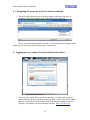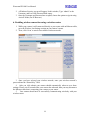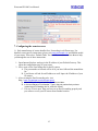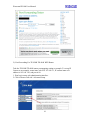
1
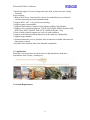
Wanscam IPCAM User Manual
Wireless/Wired Network IP Camera
Night Vision & Remote Operation
User Manual
1
Wanscam IPCAM User Manual
Thank you for buying our IP camera.
Wanscam AJ Series IP Camera products are designed and equipped for local and
remote network video surveillance system, including wired IP bullet camera, wireless IP
bullet camera, IP IR dome camera, IP IR waterproof camera, IP Pan/Tilt/Zoom Camera etc.
We adopt high performance chip to ensure high quality media processor which processes
audio and video collection, compression and transmission. Standard M-JPEG compression
format ensures clear and streaming video performance. It enables users to view live video
via IE6.0, IE7.0, IE8.0, Firefox, Google browser or other standard browser.
Wanscam AJ series IP Camera products are applicable for big, medium-sized and
small enterprises, chain store, factory, home and all kinds of spots where remote network
video transmission and control supposed to be installed, they are easy to be installed and
operated. Before the installation of the IP camera, please check if your product accessories
in the package are complete
Product Components
IP Camera ---------------------------------------------------------------------------------1 PCS
Bracket(optional)---------------------------------------------------------------------1 PCS
Power Supply- ----------------------------------------------------------------------------1 PCS
Warranty Card-----------------------------------------------------------------------------1 PCS
Certificate of Quality---------------------------------------------------------------------1 PCS
CD-------------------------------------------------------------------------------------------1 PCS
2
Wanscam IPCAM User Manual
Table of CONTENTS
1. Introduction .........................................................................................................4
1.1. Safety Introduction .........................................................................................5
1.2. Product Specifications................................................................................. ....5
1.3. Applications……….. ......................................................................................5
1.4. System Requirements……….. ........................................................................6
2. Products Panels and Controls .............................................................................6
2.1. Main Interface Introduction of AJ Series Products.........................................7
3. Installation ..........................................................................................................8
3.1. Connecting you camera to your local network ................................................8
3.2. Connecting Your Camera To Your Local Network-Continued.......................10
4. Prompting the necessary ActiveX controls.......................................... ..............12
4.1 Prompting the necessary ActiveX controls-continued...................... ...............13
5. Logging into your camera from a local internet location................................... 13
6. Enabling wireless connection using a wireless router.........................................14
7. Configuring the remote access.............................................................................15
8. Main menu interface operation...........................................................................17
8.1. Manager Operation...................................................................... ...................18
8.1.1. Basic Network Settings......................................................................... .......19
8.1.2. Basic Network Settings................................................................. ................20
8.1.3. Wireless Setting.............................................................................. ..............21
8.1.4. ADSL Setting................................................................................................21
8.1.5. Dynamic DNS Setting (DDNS)....................................................................21
8.1.6. E-mail and FTP service Settings...................................................................22
8.1.7. Alarm Service Settings.................................................................................23
8.1.8. Reset/Firm Ware Upgrade ...........................................................................24
8.1.9. Restore Factory Settings ..............................................................................24
8.1.10. Reboot Equipment .....................................................................................24
9 Warranty .............................................................................................................25
3
Wanscam IPCAM User Manual
General Introduction
IP Camera is a new generation product with the combination of analog camera &
IP video technology. Despite all functions which analog cameras have, IP camera can
compress and encrypt video and audio signal then send it to remote terminals through
internet with its built-in processor and web server. With its IP address, users can use
standard PC browser to visit IP camera, real time monitor targets, manage and store
video or image, PTZ control also is available through network.
As a new member in camera family, IP camera shares the same operation function
with the analog camera, such as, auto white balance, auto shutter speed, AGC, auto
backlight compensation etc. On the other hand, IP camera supports remote access
through internet, and support multi-user visit, some IP cameras are able to extend to
both analog and digital signal.
The core of Wanscam AJ series IP cameras is 32Bit RSIC, adopts standard MJPEG
compression format, camera sensor is CMOS, support auto white balance and backlight
compensation, support internet browser, and cell phone view. In general, according to the
function of audio simplex & duplex, infrared, wired, wireless, POE, PTZ, local storage, it
has hundreds of products, to meet requirements of high, middle, low ranks of users.
4
Wanscam IPCAM User Manual
1. Introduction
1.1 Safety Instructions
(1). Use the proper power source.
Do not use this product with a power source that supplies more than the specified
Voltage(100-240V AC).
(2). Never insert anything metallic into the camera.
Inserting metal object into the camera can be a source of dangerous electric shock.
(3). Do not operate in wet or dusty environment.
Avoid places like a damp basement or dusty hallway.
(4). Do not attempt to disassemble the camera.
You may be subjected to severe electrical shock if you attempt to take apart the camera
while the camera is connected to its power source. If there are any unusual sounds or
smells coming form the camera, unplug it immediately and contact Customer Service.
(5). Handle the camera carefully
Dropping the camera on any hard surface may cause a malfunction. If the camera does
not work properly due to physical damage, please contact Customer Service for repair or
exchange.
(6). Apply to FCC and CE Rule
This device complies with part 15 of the FCC and CE Rules. Operation is subject to the
following two conditions:
1: This device may not cause harmful interference.
2: This device must accept any interference received, including interference that may
cause undesired operation.
Any changes or modifications not expressly approved by the party responsible for
compliance could void the user’s authority to operate the equipment. This equipment
complies with FCC and CE radiation exposure limits set forth for uncontrolled
environment. This equipment should be installed and operated with minimum distance
20 cm between the radiator & your body.
This transmitter must not be co-located or operating in conjunction with any other
antenna or transmitter.
1.2. Product Specifications
*- Adopt high Performance, strong function media processor 32Bit RSIC
*- High sensor CMOS
*-Adopt optimized MJPEG video compression algorithm, realize high-definition images
transmission in narrow bandwidth;
5
Wanscam IPCAM User Manual
*-Maximum support 15 users viewing at the same time, no limit for users if using
forwarder
Server function;
*- Built in Web Server, convenient for users to use standard browse to realize the
real time monitoring and setting administration;
*-Support WIFI:802.11b/g wireless networking;
*-Support remote system update;
*-Support DDNS analysis, support LAN & Internet (ADSL,Cable Modem)
*-Support variety of network protocol: TCP/IP, UDP, SMTP, PPPoE, Dynamic DNS,
DNS Client, SNTP, BOOTP, DHCP, FTP, SNMP, WIFI/802. 11b/g
*-Parts of modes products support one/ two way audio, talkback;
*-Support motion detection alarm function (area & sensitivity Configurable);
*-Support image snapshot
*-Abnormal automatic recovery function, auto reconnection available when network
Interruption occurred.
*-Dynamic alarm function, alarm time-schedule configurable.
1.3. Applications
Wanscam AJ series products are ideal choice for big department, chain store,
supermarket, home, factory, workshop etc.
1.4. System Requirements
6
Wanscam IPCAM User Manual
2. Products Panels and Controls .
There are two kinds of the panels of Wanscam AJ series IP camera mailly divided into
two kinds: one is body guard interface, the other is the extend line interface, set two
representative products as examples, to give explanation:
*Non-extended line IP Camera icon
*Extended line IP Camera icon
7
Wanscam IPCAM User Manual
2.1. Main Interface Introduction of AJ Series Products
*Non-extended line IP Camera Tailgate
1: Audio Out , 2: Audio In
3: Ethernet interface: RJ-45 interface. Power Supply Light: constant on after power up
Network light: constant sparkle after power up data transmission.
4: Antenna:
5: Power input interface: connect direct current 5V Power
*Extension line interface definition icon:
Extension Line Of AJ Series
Power: direct current 12V.
Reset line: two reset line short circuit, equipments restore to ex- factory standards.
Ethernet interface: RJ-45 network interface.
3. Installation
3.1 Connecting you camera to your local network
8
Wanscam IPCAM User Manual
When installing the camera to the local network for the first time, the camera must be
connected to an Ethernet input on your router so that your network can locate your
camera.
1. Power on the camera in close proximity to your router.
2. Directly connect your camera to your router using the Ethernet cable.
If the yellow and green indicator lights on the camera are blinking, then your camera is
successfully communicating with your router.
3. Insert the software CD (included ) into your PC.
4. Run the program labeled “ OCX Setup” form the flie folder on the software CD.
5. After the “OCX Setup” program has installed. Please run the “ Search Tool” software.
This software is used to search the IP address of the ip camera in your local network.
Note: “ Search Tool” Software no need to install, if you need it , you can copy it to your
desktop of your PC.
9
Wanscam IPCAM User Manual
6. Click “Find” to find the IP Camera on your router. (If you have several items on your
router, Check the bottom of the camera for the factory IP setting.)
7. Once you have located the camera on your router, open the command prompt(cmd).
8. From the Command Prompt, type in “ ipconfig” then press Enter.
9. Write down the number that represents the Default Gateway, then go back into the
Search Tool.
3.2 Connecting Your Camera To Your Local Network-Continued
10
Wanscam IPCAM User Manual
10. Running the Search Tool software, If network cable and power supply are correctly
connected, device type, name and IP address will be shown in the Equipments list
(Otherwise, please confirm whether power supply and network cable work normally).
In the picture above, the configuration information of the current computer is listed on
the left side; and the network configuration information of the selected device is listed on
the right side. Default IP address of the IP camera is 192.168.1.99, and HTTP port is 99.
From the Search Tool, Select your IP camera. Here, you will need to re-address your
camera’s IP address based off of your Local Network Default Gateway. For example: If
your Default Gateway is 192.168.1.1, you should change the last set of values of your
address from 1to a larger value such as 99. Therefore, your new address will read
“192.168.1.99” (The last set of values must be lower than 254).
11. Next, change the Gateway and DNS IP address in the network setting to exactly
match your Default Gateway.
12. Now Change the Data Port to 80.
13. Last click “Apply” enter the Username and Password. The Username will be “admin”
and the Password field will remain empty.
14. Last, click “OK” and your camera will automatically reboot as it saves all changes
that you have just mode.
11
Wanscam IPCAM User Manual
*** The first time that you connect to your camera either from your local
network or from a remote network, you will need to connect using an
internet Explorer browser, and you must prompt three necessary ActiveX
controls. Please refer to Section 4 for ActiveX configuration.
4. Prompting the necessary ActiveX controls
The first time you access your camera online from a new computer(including the
LiveDemo), you will need to prompt three necessary ActiveX controls.
1. From Internet Explorer click on “Tolls” then select “ Internet Options.” Select the
“Security” tab, and then click the “Custom Level” button.
• If you are using either Windows Vista or Windows 7, please run Internet
Explorer as Administrator.
Now, change the tree following options to “Prompt”:
---Download Signed ActiveX controls
---Download Unsigned ActiveX controls
---Initialize and script ActiveX controls not marked as safe for scripting.
2. After all three ActiveX controls are prompted; please login to you camera’s IP
address. If this is your first time logging into your camera, you will type into an
internet Explorer browser http:// followed by the IP address that you’ve entered
into the IP address field of the network setting section. For example, the address
will look like this: Http://192.168.1.99
12
Wanscam IPCAM User Manual
4.1 Prompting the necessary ActiveX controls-continued
3. This will usually prompt you or a bar may appear on the top of the page. If
prompted, select run or install. Click on the yellow bar to proceed.
*If you are using Internet Explorer version 9.0 , this prompt bar will appear on the
bottom of your browser instead of at the top of your browser.
5. Logging into your camera from a local internet location
1. To access your camera from your local connection, you will need to open an
Internet Explorer browser. In the browser, type Http:// followed by the IP address
that you’ve entered into the IP address field of the network setting section. For
Example, The address will look something like this : Http://192.168.1.99
13
Wanscam IPCAM User Manual
2. A Windows Security pop-up will appear. In this window, Type “admin” as the
Username, and Leave the Password field empty.
3. Once the Username and Password are accepted, choose the option to sign in using
ActiveX Mode (For IE Browser).
6. Enabling wireless connection using a wireless router
1. While your camera is still connected directly to your router with an Ethernet cable,
go to the Wireless Lan Settings section on your camera’s menu.
2. Next, click ‘Scan’ to search for available wireless networks.
3. Once you have selected your wireless network, enter your wireless network’s
password into the “Shared Key” field.
4. After you click submit your camera should automatically reboot to save these
settings. Please wait 30 seconds after your camera has rebooted, then you may disconnect
the Ethernet cable that is connecting your camera to your router.
5. Your camera should now be successfully communicating wirelessly with your
wireless router.
14
Wanscam IPCAM User Manual
7. Configuring the remote access
1). Each manufacturer of routers handles Port Forwarding in a different way. For
detailed, router specific instructions, please visit www.portforward.com and find the model
of your router. Then select ‘Default Guide’ for detailed screenshots and use them to help
you through the rest of these instructions.
1. Open Internet Explorer and type in the IP address of your Default Gateway. This
opens the configuration page of your router.
2. Next, create a Port Forwarding rule for the IP camera.
A. The port number to forward will be 80 if you have followed the manual thus
far.
B. Your Router will ask for an IP address as well. Input the IP address of your
IP camera.
3. After creating the Port Forwarding rule, visit
Http:// www.yougetsignal.com/tools/open-ports/
A. Write down your external address, it will be used later.
B. In the box that says ‘Port Number’, Type in the port number that you have
created a port Forwarding rule for, and click “Check”
C. If it says ‘Port is open’ then you have set up Port Forwarding properly and
you can now access your IP camera from another location.
15
Wanscam IPCAM User Manual
2). Port Forwarding For TP-LINK TD-8840 WIFI Router
Take the TP-LINK TD-8840 router port mapping setting as example. To set up IP
Camera as an example: router inner web IP is 192.168.1.1, IP camera inner web
address is 192.168.1.50, and port is 80.
1. First log in router web administration interface.
2. Click in front of left side “Advanced Setup
16
Wanscam IPCAM User Manual
3. Click “virtual server” in the unfolded menu.
4. fill “80” under the right port start or port end, Server IP address fill
"192.168.1.50", protocol select "TCP/UDP"OR”“TCP”, finally don’t forget click
under “"save/apply”
1. DLINK ex-factory definition router address is 192.168.0.1
2. Linksys ex-factory definition router address is 192.168.1.1
3. 3com ex-factory definition router address is 192.168.2.1
4. Microsoft ex-factory definition router address is 192.168.2.1
5. Net gear ex-factory definition router address is 192.168.1.1
6. Asus ex-factory definition router address is 192.168.1.1
8. Main menu interface operation
17
Wanscam IPCAM User Manual
For example: If the
is a bright , indicating the device is the first way to monitor the
status.
When you log on the operator interface, you can perform PTZ and video parameters
Direction control: Click the arrows in different directions can be the lens to the
appropriate direction of rotation
Vertical cruise
Level cruise
1. Image mirror indicates a reverse image.
2. Resolution, mode, brightness, contrast default setting are:320*240、50HZ、6、4、
mode is mainly for the adjustment of Light strength, please adjust to 60HZ when light is
poor or in dark.
3. There are 3 browse modes in IE mode: visitor, operator, administrator, the authority
of administrator is the highest, log in different authorities, the operation will be
different. Regarding to 3 user authorities, please refer to 3.4.4. Equipment User
Administration.
If you want to see 4-way,or 9-way, you can click the icon
or
OSD: In the video display date and time. You can disable the OSD function or choose the
color of OSD.
Snapshot Photo: Click the icon
interception photo.
icon to enter the recording mode, the icon becomes
Video: Click
the end of the recording.
,again, click
8.1. Manager Operation
When you logged on as Administrator, click on “Administrator action” to enter setting
interface. Device Information: You can see the device serial number, equipment systems
and device firmware version of the application firmware version of the.
Alias setting : You can set your favorite device aliases.
Date&Time set : seting the date and time.
Uer settings : Can be set up to 8 users. On this page you can set up accounts of the user
name, password, as well as in their packet (administrator, operator, visitor).
z Visitor : In this mode, you can only visit.
z Operator :You can set the direction of the lens device, set the video screen’s
brightness, contrast and other parameter.
z Administrator : You can set the device advanced configuration.
UPnP set :If you want internet access IPCAM, to ensure that the state is successful UPnP.
Device Firmware Upgrade: The system firmware update the device firmware and
application of
Restore factory settings : When there is not a response when the error occurred, you can
restore the factory settings to resolve the device.
18
Wanscam IPCAM User Manual
I rebooted the device :I rebooted the device.
Back: Return to monitor mode
8.1.1 Multi-Device Settings
z
Add a local area network equipment
In the multi-device configuration page, you can see all the equipment inside the LAN.
The first device is the default device. You can add more devices listed in the list of
equipment. Embedded applications, up to 4 devices at the same time-line. Click the
“second road equipment” and double-click “Current list of devices in the LAN” in the
device entry name, host address, Http port will automatically be filled, require the user to
fill in the correct account name and password, click “Add.” Repeat this process you can
continue to add devices. Finally do not forget to click on the “Settings” button.
z
Add a device on the internet
First, make sure you want to add devices to access via IP address or domain name. For
example:http://202.96.133.134: 9008 or http://IPcam.dyndns.org:9008. And then fill in
host address: 202.96.133.134 HttpPort: 9008 or host address: IPcam.dyndns.org Http
port: 9008. and fill in the correct account name and password to the last click on “Add.”
Repeat the above steps can add other devices
19
Wanscam IPCAM User Manual
8.1.2 Basic Network Settings
This sector is for DHCP and IP configuration,port forwarding is needed, If you
choose to set IP address,please fill in the relative IP address、subnet mask, gateway,
DNS server, Http port;
20
Wanscam IPCAM User Manual
8.1.3
Wireless Setting
For the details please view “6. Enabling wireless connection using a wireless router”.
Page 14th.
8.1.4 ADSL Setting
When your device directly connected to the Internet via ADSL, when you need to enter
fill in your ISP service providers obtain from the account name and password. Duly
completed and click “Settings” button. Your device can connect to the internet has.
8.1.5 Dynamic DNS Setting (DDNS)
All the above information is set up when the device is ready to deliver; users
generally do not need to change. In case of any accidental loss, user needs to re-obtain
the domain name, and fill it himself, juts do as the above, the user’s name is just the
first four characters, and this is for remote access. For example, http://abcd.viipcam.com
the user’s name is abcd. The password is DDNS. (The password can be obtained on
the device body or contact the supplier). When connected, it displays "xxxxx is OK"
on Device Info; it means that it was successfully set. If you need to use your own
Dynamic DNS, please select the appropriate service providers (on DDNS service)
then enter the following information, then save it;.
21
Wanscam IPCAM User Manual
8.1.6 E-mail and FTP service Settings
The above setting is a preparation for the alarm function, the sender should be
entered the sender’s email address,recipient 1、2、3、4 is filled with recipient E-mail
address;SMTP server should be filled with the sender email SMTP server,e.g. the
sender email address is [email protected],and enter mail.163.com. Generally SMTP port
is 25,do no need to change;when needs to check, just tick it, and enter SMTP user
and SMTP password,both of them are provided by Email provider,and test according
to reference;when needs to send, please tick Email notification Internet IP address;
The e-mail server and other information can be obtained from the mail service
provider the email notification is image captured when alarming if no email
notification is needed when alarming, and then no need to enter.
Set up FTP service, you can fill in parameters like following:
22
Wanscam IPCAM User Manual
The above setting is equally similar to Mail Server Settings,when alarming is
triggered it also sends image,please enter FTP server、FTP port、FTP user、FTP
password, FTP upload directory、FTP mode,FTP mode has two options: PORT and
POSV. If needs a quick upload image, then select it, edit upload image interval
(second)
8.1.7 Alarm Service Settings
As shown below, there are two modes of alarm trigger, first one is motion detection,
pleas refer to below interface,the sensitivity of motion detection can be adjusted
according to the users′ requirement, the higher the number is, the lower sensitivity
is; Another mode is input alarm, when connected, it triggers alarm through alarm
input signal which connects to linkage alarm GPIO;
When triggered, there are 3 alarm modes:one is IO alarm linkage, camera connects
with linkage alarm box through GPIO, sound the siren ;the second is email
notification, send email with images captured;the last is upload pictures alarm,as the
way mentioned before FTP upload pictures alarm, Upload pictures interval(second)
keeps consiste nt with the mentioned upload pictures interval of Ftp service settings.
The schedule refers to arming time,as the selected time interval: 0:00 minute per
week to 0:45 minutes and Monday 1:00 hour and 2:00 hour
Figure3.15
23
Wanscam IPCAM User Manual
8.1.8 Reset/Firm Ware Upgrade
This sector is for camera firmware upgrade, it includes device system firmware
and device application firmware
Be cautious to apply for it!
8.1.9 Restore Factory Settings
When users forget password, we can restore ex-factory settings, when click, a picture
will pop up, Click ok, and wait for 1 minute and you can use it normally. User setting
feature restores
8.1.10 Reboot Equipment
Click restart, it appears the above picture, click ok, wait for 1 minute and you can
use it normally
24
.
Wanscam IPCAM User Manual
9. Warranty
Under normal use condition, products resulting from its own failures in the
warranty period will be free maintenance. Warranty Terms as following:
a) Charge-free maintenance of the product is one year. We can repair it for free
during the guarantee period (Damages not caused by misuse or vandalism).
Repair over guarantee period, we will charge maintenance fee.
b) During guarantee period, breakdown caused by misuse or other reasons out of
range of warranty. You could ask repair depend on the card. We only charge for
changed components, the maintenance charge is free.
c) When the products need maintenance, hand up the card with products to the
manufacture or local distributor.
d) Take apart item crust, tear up the sealing label privately, this is out of
warranty range.
e) We do not accept the damaged item due to modification or add other
functions.
The Following Circumstances will not be free warranty
a) Period check, maintenance or change components due to normal attrition.
b) The damages due to crash, extrusion, artificial flooding, moisture or other
personal reasons.
c) The damages due to floods, fire, lightning strike and other natural calamities
or force majeure incidents factors
d) Repaired item by non-authorized repair centers.
All above terms, if changed, regarded to relevant regulations.
THAT’S ALL, THANK YOU!
25