1
RCS20 M:N Redundancy Switch
Table of Contents
Table of Contents
Section 1 – Introduction
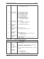
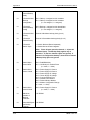
1.0 Description _______________________________________________________ 1-1
1.1 Digital Data Switch (DDS20) _________________________________________ 1-1
1.2 Intermediate Frequency Switch (IFS20) ________________________________ 1-1
1.3 General Information ________________________________________________ 1-1
1.4 Channel Definitions ________________________________________________ 1-2
Section 2 – Installation
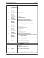
2.0 Installation Requirements____________________________________________ 2-1
2.1 Unpacking the System ______________________________________________ 2-1
2.1.1 List of Items_____________________________________________________ 2-1
2.1.2 In Case of Shipping Damage _______________________________________ 2-1
2.1.3 Test Data Sheet _________________________________________________ 2-1
2.2 Site Considerations ________________________________________________ 2-2
2.2.1 Power Sources __________________________________________________ 2-2
2.3 Rack Mounting ____________________________________________________ 2-2
2.4 System Cable Configuration _________________________________________ 2-3
2.5 System DIP Switch and Jumper Settings _______________________________ 2-5
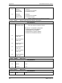
2.5.1 Data Switch Module DIP Switch Configuration__________________________ 2-5
2.5.2 Reference Distribution Module ______________________________________ 2-9
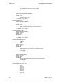
2.6.1 J1 - SD - Send Data _____________________________________________ 2-11
2.6.2 J2 - DDO - Drop Data Out ________________________________________ 2-12
2.6.3 J3 - IDI - Insert Data In____________________________________________ 2-12
2.6.4 J4 - RD - Receive Data___________________________________________ 2-12
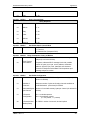
2.6.5 J5 - ESC Audio _________________________________________________ 2-12
2.6.6 J6 - ES/ES_____________________________________________________ 2-13
2.6.7 J7 – ESC Alarm Interface _________________________________________ 2-13
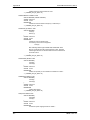
2.6.8 J8 - ESC 8K Data Interface________________________________________ 2-14
2.6.9 J9- G.703 (Balanced) ____________________________________________ 2-15
2.6.10 J10 - Sync Data________________________________________________ 2-15
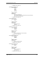
2.6.11 Digital Data Switch (DDS20) J1 through J10 - Switch Connector _________ 2-16
2.6.12 RCU20 Connector Pinouts _______________________________________ 2-19
TM056 – Rev. 2.3
vii