1
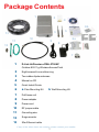
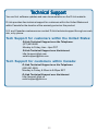
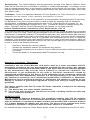
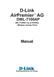
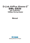
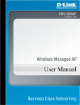
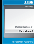
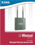
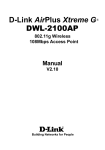
D-Link AirPremierTM
DWL-2700AP
Outdoor 802.11g
Wireless Access Point
Manual
This product should be installed ONLY by
experienced, professional installers who are
familiar with local building and safety codes, and
wherever applicable, are licensed by the
appropriate authorities. Failure to do so may void
the warranty and may expose the user or the
service provider to legal and financial liabilities.
Building Networks for People
Contents
Package Contents ................................................................................3
Introduction............................................................................................4
Features ...............................................................................................5
Five Operational Modes ........................................................................6
Using the Configuration Utility ................................................................7
Technical Specifications ......................................................................27
Contacting Technical Support ..............................................................30
Warranty..............................................................................................31
Registration ........................................................................................34
2
Package Contents
1
2
4
6b
5
3
13
11
10
9
12
6a
8
7
1
D-Link AirPremierTM DWL-2700AP
Outdoor 802.11g Wireless Access Point
2
Eight screws & one rubber ring
3
Two rubber dipole antennas
4
Manual on CD
5
Quick Install Guide
6
a Pole-Mounting Kit
7
PoE base unit
8
Power adapter
9
Power cord
10
RF jumper cable
11
Grounding wire
12
Surge arrestor
13
30m Ethernet cable
b Wall-Mounting Kit
If any of the above items are missing, please contact your reseller.
3
Introduction
The DWL-2700AP covers a large operating distance, providing an 802.11g outdoor WLAN
which enables users to access the Internet or an organization’s network.
At up to five times the speed of previous wireless devices, you can work faster and more
efficiently, increasing productivity. With the DWL-2700AP, bandwidth-intensive applications
like graphics or multimedia will benefit significantly because large files are able to move
across the network quickly.
The D-Link AirPremierTM DWL-2700AP features a die-cast watertight housing and a
built-in lightning protector to protect the access point from harsh environmental conditions,
including extreme variance in temperature. It also includes Power over Ethernet (POE)
and a unique outdoor remote-mounted design for easy installation in either wall or pole
mounting.
The DWL-2700AP is suitable for manufacturing plants, industrial sites, military bases,
universities, hotels, airports and golf courses.
Configurable in five different modes (access point, bridge, multi-point bridge, wireless
client and repeater), the DWL-2700AP offers 128-bit encryption, WPA and 802.1X
authentication when used with a RADIUS server, MAC address access control, and
additional security features.
The DWL-2700AP is easy to manage with its Web-based user interface and Telnet
configuration. For Enterprise networks, the DWL-2700AP supports SNMP v.3 network
administration and real-time network traffic monitoring via D-Link’s D-View Network
Management software.
System Requirements for Configuration:
Computers with Windows, Macintosh, or Linux-based
operating systems with an installed Ethernet adapter
Internet Explorer version 6.0 or Netscape Navigator version
6.0 and Above
4
Features
Ideal for Internet Hotspots - Provides outdoor users with wireless Internet
access.
Robust Outdoor Housing - Designed for harsh outdoor environments, with
die-cast, watertight housing, built-in heater and temperature sensor, and either
pole or wall- mounting.
5 Different Operation modes with WDS (Wireless Distribution System) Capable of operating in one of five different operation modes to meet your
wireless networking requirements: access point (AP), Point-to-Point (PtP)
bridge, Point-to-multipoint (PtMP) bridge, wireless client, or repeater.
Embedded DHCP Server automatically assigns IP addresses to wireless
clients.
Connect networks in different buildings when used in conjunction with
D-Link’s high-gain outdoor antennas.
Easy Installation with 802.3af PoE.
Faster wireless networking* with the 802.11g standard to provide a wireless
data rate of up to 54Mbps.
Compatible with the 802.11b standard to provide a wireless data rate of up to
11Mbps with 802.11b devices - that means you can migrate your system to the
802.11g standard on your own schedule without sacrificing connectivity.
Better security with ACL,WPA, AES and 802.1X- The DWL-2700AP can se-
curely connect to wireless clients on the network using WPA (Wi-Fi Protected
Access) providing a much higher level of security for your data and communications than has previously been available. In conjunction with a RADIUS server,
802.1X authentication verifies the identity of would-be clients.
Supports up to 152-bit WEP encryption and AES (Advanced Encryption
Standard).
Multiple Management options - Great for enterprise wireless network management
SNMP v.3
D-Link’s D-View Network Management software
Web-based configuration
Telnet
*Maximum wireless signal rate based on IEEE Standard 802.11g specifications.
Actual data throughput will vary.
5
Five Operational Modes
AP Mode
Bridge Mode
6
Using the Configuration Utility
To configure the DWL-2700AP, use a computer which is connected to the DWL-2700AP
with an Ethernet cable (see the Network Layout diagram).
First, disable the Access the Internet using a proxy server function. To disable
this function, go to Control Panel > Internet Options > Connections > LAN
Settings and uncheck the enable box.
Start your web browser program (Internet Explorer, Netscape Navigator) .
Type the IP address and http port of the DWL-2700AP in the address field
(http://192.168.0.50) and press Enter. Make sure that the IP addresses of the
DWL-2700AP and your computer are in the same subnet.
http://192.168.0.50
7
Using the Configuration Utility (continued)
After the connection is established, you will see the user identification window as shown.
Note: If you have changed the default IP address assigned to the DWL-2700AP,
make sure to enter the correct IP address.
Type admin in the User Name field
Leave the Password field blank
Click OK
Home > Wizard
The DWL-2700AP is a Wireless Access Point. The setup wizard will guide you through the
configuration of the DWL-2700AP. The DWL-2700AP’s easy setup will allow you to have
wireless access within minutes. Please follow the setup wizard step by step to configure the
DWL-2700AP.
The Home>Wizard screen will appear. Please refer to the Quick Installation Guide for
more information regarding the Setup Wizard.
8
Using the Configuration Utility (continued)
Home > Wireless
Wireless
BandSSID-
SSID
Broadcast-
Channel-
802.11g
Service Set Identifier (SSID) is the name designated for a specific wireless local area network (WLAN). The SSID’s factory default setting is
default. The SSID can be easily changed to connect to an existing
wireless network or to establish a new wireless network.
Enable or Disable SSID Broadcast. Enabling this feature broadcasts the
SSID across the network.
6 is the default channel. All devices on the network must share the same
channel.
Radio
Frequency-
The radio frequency will remain at 2.437 GHz .
Apply-
Click Apply to save the changes.
9
Using the Configuration Utility (continued)
Home > LAN
LAN is short for Local Area Network. This is considered your internal network. These are
the IP settings of the LAN interface for the DWL-2700AP. These settings may be referred
to as private settings. You may change the LAN IP address if needed. The LAN IP
address is private to your internal network and cannot be seen on the Internet.
Get IP From-
Select Static (Manual) or Dynamic (DHCP) as the method you
will use to assign an IP address to the DWL-2700AP.
IP Address-
The IP address of the LAN interface. The default IP address is:
192.168.0.50
Subnet Mask-
The subnet mask of the LAN interface.
The default subnet mask is 255.255.255.0
Default Gateway-
This field is optional. Enter in the lP address of the router on your
network.
Apply-
Click Apply to save the changes.
10
Using the Configuration Utility (continued)
Advanced > Mode
The DWL-2700AP can be
configured to perform in any of
five modes: wireless access
point, wireless client, wireless
bridge, multi-point bridge,
repeater.
Access Point is the default
setting. This mode is used to
create a wireless LAN.
PtP Bridge will allow you to
connect two LANs together.
The wireless bridge mode will
work only with another DWL2700AP. Click to enable and
enter the MAC address of the
remote bridge.
PtMP Bridge will allow you
to connect multiple wireless
LANs together. Other wireless
LANs must be using DWL2700APs. Click to enable and
enter up to 8 remote AP MAC addresses.
AP Repeater will allow you to repeat the wireless signal of a DWL-2700AP access
point. Click to enable and enter the MAC address of the root AP.
AP Client will transform any IEEE 802.3 Ethernet device (e.g., a computer, printer, etc.)
into an 802.11b wireless client when it communicates with another DWL-2700AP that is
acting as an AP. Click to enable and enter the MAC address of the root AP.
Apply - Click Apply if you have made any changes.
Find the MAC address of the DWL-2700AP that is acting as a Remote Access
Point or a Remote Bridge, by going to Status > Device Info in the configuration utility of the remote DWL-2700AP. There you will find the MAC address.
MAC Address - (Media Access Control Address) is a unique hardware address
that identifies a device on a network. It is assigned at the factory and cannot be
changed. Usually you will find this address on a sticker on the device or on the
packaging.
11
Using the Configuration Utility (continued)
Advanced > Performance
Wireless Band802.11g
Turbo SettingThis function is set to
Disabled. It cannot be
Enabled.
FrequencyThe frequency remains at
2.437 GHz.
Channel-
Data RateBeacon
Interval-
DTIM-
Fragment
Length-
RTS LengthTransmit
Power-
Select from channels 1-11.
(FCC 1-11; ETSI 1-13).
The Data Rates are Auto, 1Mbps, 2Mbps, 5.5Mbps, 6Mbps, 9Mbps,
11Mbps, 12Mbps, 18Mbps, 24Mbps, 36Mbps, 48Mbps, 54Mbps.
Beacons are packets sent by an access point to synchronize a network. Specify a beacon interval value. The default (100) is recommended.
(Delivery Traffic Indication Message) - 1 is the default setting. DTIM
is a countdown informing clients of the next window for listening to
broadcast and multicast messages.
The fragmentation threshold, which is specified in bytes, determines
whether packets will be fragmented. Packets exceeding the 2346
byte setting will be fragmented before transmission. 2346 is the default setting
This value should remain at its default setting of 2,346. If you encounter inconsistent data flow, only minor modifications to the value
range between 256 and 2,346 are recommended
Choose full, half (-3dB), quarter (-6dB), eighth (-9dB), minimum power.
12
Using the Configuration Utility (continued)
Advanced > Filters > Wireless Access Settings
Wireless Band-
802.11g
Access Control-
Select Disabled to disable the filters function.
Select Accept to accept only those devices with MAC addresses
in the Access Control List.
Select Reject to reject the devices with MAC addresses in the
Access Control List.
Access Control
List-
The MAC addresses in this list can be accepted or rejected for
inclusion in the network, depending upon the Access Control
selection.
Apply-
Click Apply to save the changes.
13
Using the Configuration Utility (continued)
Advanced > Filters > WLAN Partition
Wireless Band-
802.11g
Inter-Wireless
Client Connection- Enabling this feature allows wireless clients to communicate
with each other. If this is disabled, wireless stations of the selected band are not allowed to exchange data through the Access Point.
Ethernet to
WLAN Access-
Apply-
Enabling this feature allows Ethernet devices to communicate
with wireless clients . If this is disabled, all data from the Ethernet
to associated wireless devices is blocked. Wireless devices can
still send data to the Ethernet.
Click Apply to save the changes.
14
Using the Configuration Utility (continued)
Advanced > Encryption
WPA & 802.1x - represent
the first line of defense
against network intrusion. In
the authentication process
the RADIUS server verifies the
identity of the client attempting to connect to the network.
Unfamiliar clients will be denied access. EAP(Extensible
Authentication Protocol) is
available through the Windows XP Operating System.
You will need to use the
same type of EAP protocol on
all the devices in your network when using the 802.1x
feature.
Wireless Band- 802.11g
Authentication-
Select Open System to communicate the key across the
network.
Select Shared Key to limit communication to only those devices
that share the same WEP settings.
Select Open System/Shared Key to communicate the key and
require identical WEP settings to communicate.
Select 802.1X for increased security features with a RADIUS server.
Select WPA to utilize the increased security with a RADIUS server.
When you select WPA-PSK you will enter a PassPhrase below.
PassPhrase- When you select WPA-PSK you will enter a Passphrase.
Cipher-
When you select WPA or 802.1X the EAP type will be selected for you.
Encryption- Select Enabled to use WEP Encryption security.
Key Type-
Select HEX or ASCII.
Key Size-
Select 64-, 128-, 152-bits.
Valid Key-
Select the First through the Fourth key to be the active key.
Key Table-
Input up to four keys for encryption.You will select one of these
keys in the valid key field.
Apply-
Click Apply to save changes.
15
Using the Configuration Utility (continued)
Advanced > Grouping
Load Balance-
Select Enabled or Disabled.
When you Enable Load Balance you allow several DWL-2700APs to balance
wireless network traffic and wireless clients among the DWL-2700APs in the
network. Assign each access point a different non-overlapping channel (e.g., 1,
6, 11).
User Limit (0-64)- Set the User Limit in this field (0-64).
Link Integrate-
Select Enabled or Disabled.
When Link Integrate is Enabled, whenever the Ethernet connection
between the LAN and the AP is disconnected - then the wireless
segment associated with the AP will also be disconnected from the AP.
Ethernet Link
Status-
This field displays the Ethernet Link Status. Link Up indicates
that there is an Ethernet LAN connection to the AP.
Click Apply-
Click Apply to save the changes.
16
Using the Configuration Utility (continued)
Advanced > DHCP Server > Dynamic Pool Settings
DHCP Server
ControlEnable or Disable
the DHCP function
here.
Dynamic Pool
SettingsIP Assigned FromEnter the starting IP
address in the
range.
The Range of
Pool (1-256)Enter the number
(quantity) of IP addresses in the
range.
SubMask-
Enter the subnet mask here.
Gateway-
Enter the IP address of the router on the network.
Wins-
Windows Internet Naming Service is a system that determines
the IP address of a network computer that has a dynamically assigned IP address.
DNS-
Enter the IP address of the DNS server. The DNS server translates
domain names such as www.dlink.com into IP addresses.
Domain Name-
Enter the Domain Name of the DWL-2700AP.
Lease Time (6031536000 sec)- The Lease Time is the period of time before the DHCP server will
assign new IP addresses.
Status-
Turn the Dynamic Pool Settings ON or OFF here.
17
Using the Configuration Utility (continued)
Advanced > DHCP Server > Static Pool Settings
DHCP Server
ControlEnable or Disable
the DHCP function
here.
Static Pool
SettingsAssigned IPEnter the static IP
address of the device here.
Assigned MAC
AddressEnter the MAC address of the device
here.
SubMask-
Enter the subnet mask here.
Gateway-
Enter the IP address of the router on the network.
Wins-
Windows Internet Naming Service is a system that determines
the IP address of a network computer that has a dynamically assigned IP address.
DNS-
Enter the IP address of the DNS server. The DNS server translates
domain names such as www.dlink.com into IP addresses.
Domain Name-
Enter the Domain Name of the DWL-2700AP.
Status-
Turn the Static Pool Settings ON or OFF here.
Assigned Static
PoolAfter you have input the Static Pool Settings for each device, click
Apply and the profile will appear in this list at the bottom of the
window.
18
Using the Configuration Menu (continued)
Advanced > DHCP Server > Current IP Mapping List
This screen displays information about the current DHCP dynamic and static IP address
pools. This information is available when you enable the DHCP function of the DWL2700AP and assign dynamic and static IP address pools.
Current DHCP Dynamic Pools-These are IP address pools to which the DHCP
server function has assigned dynamic IP addresses.
Binding MAC address- The MAC address of a device on the network
that is within the DHCP dynamic IP address
pool.
Assigned IP address-
The current corresponding DHCP-assigned
dynamic IP address of the device.
Lease Time-
The length of time that the dynamic IP address
will be valid.
Current DHCP Static Pools-These are IP address pools to which the DHCP server
function has assigned static IP addresses.
Binding MAC address- The MAC address of a device on the network
that is within the DHCP static IP address pool.
Assigned IP address-
The current corresponding DHCP-assigned
static IP address of the device.
19
Using the Configuration Utility (continued)
Tools > Admin
User Name-
Enter a user name; admin is the default setting.
Old Password-
To change your password, enter your old password here
New Password-
Enter your new password here.
Confirm New
Password-
Enter your new password again.
20
Using the Configuration Utility (continued)
Tools > System
Restart-
Apply settings and Restart.
Restore-
Restore to factory default settings.
21
Using the Configuration Utility (continued)
Tools > Firmware
Update FileAfter you have downloaded the most recent version of the firmware from
www.support.dlink.com you can browse your hard drive to locate the downloaded file.
Click OK to update the firmware.
22
Using the Configuration Utility (continued)
Tools > Cfg File
Update FileBrowse for the configuration settings
that you have saved
to your hard drive.
Click OK when you
made your selection.
Load Settings to
the Local Hard
DriveClick OK to load the
selected settings.
Tools > Misc.
Telnet Settings
StatusClick to Enable a
Telnet session.
TimeoutSelect a time period
after which a session timeout will
occur.
23
Using the Configuration Utility (continued)
Status > Device Info
This window displays the settings
of the DWL2700AP, as well
as the Firmware
version and the
MAC address.
Status > Stats
This window displays the statistics of the wireless
local area network.
24
Using the Configuration Utility (continued)
Note: The following two screens contain information about the device that is
communicating with the DWL-2700AP. This information is available only
when the DWL-2700AP is in point-to-point, client or repeater mode.
Status > Indication
Temperature
IndicationIndicates the
current temperature.
RSSI (Receiving
Signal Strength
Indication) Indicates the
RSSI voltage.
Available only in
PtP Bridge, AP
Repeater, and
AP Client
modes.
MAC -
Status > Client Info
The MAC address
of the device communicating with
the DWL-2700AP.
Band The device is set
to the 802.11g
band.
Authentication The device is set
to Open System.
RSSI The device is set
to Open System.
Power Saving
Mode - In this case, the communicating device is set to Power Save Off.
25
Using the Configuration Utility (continued)
Help
At this window you can access the help screens for the topics listed.
26
Technical Specifications
Standards
• IEEE 802.11b
• IEEE 802.11g
• IEEE 802.3
• IEEE 802.3u
• IEEE 802.3x
Device Management
• Web-Based – Internet Explorer v6 or later; Netscape Navigator v6 or later; or other
Java-enabled browsers.
• Telnet
• AP Manager
• SNMP v.3
Data Rate*
For 802.11b:
• 11, 5.5, 2, and 1Mbps
For 802.11g:
• 54, 48, 36, 24, 18, 12, 9 and 6Mbps
Security
• 64-, 128-, 152-bit WEP
• WPA – Wi-Fi Protected Access
(WPA-TKIP and WPA-PSK)
• 802.1x (EAP-MD5/TLS/TTLS)
• MAC Address Access Control List
• SSID Broadcast Disable function/
AP Hidden function
Wireless Frequency Range
• 2.4GHz to 2.4835GHz
Radio and Modulation Type
For 802.11b:
DSSS:
• DBPSK @ 1Mbps
• DQPSK @ 2Mbps
• CCK @ 5.5 and 11Mbps
For 802.11g:
OFDM:
• BPSK @ 6 and 9Mbps
• QPSK @ 12 and 18Mbps
• 16QAM @ 24 and 36Mbps
• 64QAM @ 48 and 54Mbps
DSSS:
• DBPSK @ 1Mbps
• DQPSK @ 2Mbps
• CCK @ 5.5 and 11Mbps
Antenna Type
• Monopole antennas with 5dBi gain
*Maximum wireless signal rate based on IEEE Standard 802.11b and 802.11g specifications. Actual data
throughput will vary.
27
Technical Specifications (continued)
Receiver Sensitivity
For 802.11b:
• 1Mbps: -92dBm
• 2Mbps: -89dBm
• 5.5Mbps: -88dBm
• 11Mbps: -83dBm
For 802.11g:
• 1Mbps: -92dBm
• 2Mbps: -89dBm
• 5.5Mbps: -88dBm
• 6Mbps: -87dBm
• 9Mbps: -86dBm
• 11Mbps: -85dBm
• 12Mbps: -88dBm
• 18Mbps: -83dBm
• 24Mbps: -80dBm
• 36Mbps: -76dBm
• 48Mbps: -71dBm
• 54Mbps: -66dBm
Wireless Operating Range1
802.11g (Full Power with 5dBi gain diversity dipole
antenna)
Indoor:
• 98ft (30m) @ 54Mbps
• 112ft (34m) @ 48Mbps
• 128ft (39m) @ 36Mbps
• 154ft (47m) @ 24Mbps
• 184ft (56m) @ 18Mbps
• 217ft (66m) @ 12Mbps
• 259ft (79m) @ 9Mbps
• 325ft (99m) @ 6Mbps
Outdoor:
• 367ft (112m) @ 54Mbps
• 820ft (250m) @ 18Mbps
• 1,640ft (500m) @ 6Mbps
Transmit Output Power2
(ETSI = 20dBm max. EIRP)
For 802.11b:
• 100mW (20dBm)
• 50mW (17dBm)
• 30mW (15dBm)
• 20mW (13dBm)
• 10mW (10dBm)
• 5mW (7dBm)
• 1mW (0dBm)
For 802.11g:
• 200mW (23dBm)
• 63mW (18dBm)
• 30mW (15dBm)
• 20mW (13dBm)
• 10mW (10dBm)
• 5mW (7dBm)
• 1mW (0dBm)
1
Environmental factors may adversely affect range.
2
Maximum power setting will vary according to individual country regulations.
28
Technical Specifications (continued)
LEDs
• Power
• 10/100M
• RSSI level
• 802.11b/g
Operating Voltage
• 48VDC +/- 10% for PoE
Current Consumption
• Max.7W without PoE (without heater)
• Max.8.5W with PoE (without heater)
• Max.27W without PoE (with heater)
• Max.28.5W without PoE (with heater)
Temperature
• Operating: -40ºF to 140ºF (-40ºC to 60ºC)
• Storing: -40ºF to 149ºF (-40ºC to 65ºC)
Humidity
• Operating: 10%~90% (non-condensing)
• Storing: 5%~95% (non-condensing)
Certifications
• FCC Part 15
• CE:
EN 55024
EN 60950
EN 301489-17
Dimensions
• L = 10.93 inches (277.7mm)
• W = 6.10 inches (155mm)
• H = 1.77 inches (45mm)
Warranty
• 1 Year
29
Techni
cal Support
echnical
You can find software updates and user documentation on the D-Link website.
D-Link provides free technical support for customers within the United States and
within Canada for the duration of the warranty period on this product.
U.S. and Canadian customers can contact D-Link technical support through our web
site, or by phone.
Tech Support for customers within the United States:
D-Link Technical Support over the Telephone:
(877) 453-5465
Monday to Friday, 6am - 6pm PST
D-Link Technical Support over the Internet:
http://support.dlink.com
email:[email protected]
Tech Support for customers within Canada:
D-Link Technical Support over the Telephone:
(800) 361-5265
Monday to Friday, 8:30am to 9:00pm EST
D-Link Technical Support over the Internet:
http://support.dlink.ca
email:[email protected]
30
Warranty
(USA only)
Subject to the terms and conditions set forth herein, D-Link Systems, Inc. (“D-Link”) provides this Limited
warranty for its product only to the person or entity that originally purchased the product from:
•
•
D-Link or its authorized reseller or distributor and
Products purchased and delivered within the fifty states of the United States, the District of Columbia,
U.S. Possessions or Protectorates, U.S. Military Installations, addresses with an APO or FPO.
Limited Warranty: D-Link warrants that the hardware portion of the D-Link products described
below will be free from material defects in workmanship and materials from the date of original retail
purchase of the product, for the period set forth below applicable to the product type (“Warranty
Period”), except as otherwise stated herein.
1-Year Limited Warranty for the Product(s) is defined as follows:
•
•
•
Hardware (excluding power supplies and fans) One (1) Year
Power Supplies and Fans One (1) Year
Spare parts and spare kits Ninety (90) days
D-Link’s sole obligation shall be to repair or replace the defective Hardware during the Warranty Period
at no charge to the original owner or to refund at D-Link’s sole discretion. Such repair or replacement will
be rendered by D-Link at an Authorized D-Link Service Office. The replacement Hardware need not be
new or have an identical make, model or part. D-Link may in its sole discretion replace the defective
Hardware (or any part thereof) with any reconditioned product that D-Link reasonably determines is
substantially equivalent (or superior) in all material respects to the defective Hardware. Repaired or
replacement Hardware will be warranted for the remainder of the original Warranty Period from the date
of original retail purchase. If a material defect is incapable of correction, or if D-Link determines in its sole
discretion that it is not practical to repair or replace the defective Hardware, the price paid by the original
purchaser for the defective Hardware will be refunded by D-Link upon return to D-Link of the defective
Hardware. All Hardware (or part thereof) that is replaced by D-Link, or for which the purchase price is
refunded, shall become the property of D-Link upon replacement or refund.
Limited Software Warranty: D-Link warrants that the software portion of the product (“Software”)
will substantially conform to D-Link’s then current functional specifications for the Software, as set forth
in the applicable documentation, from the date of original retail purchase of the Software for a period of
ninety (90) days (“Warranty Period”), provided that the Software is properly installed on approved
hardware and operated as contemplated in its documentation. D-Link further warrants that, during the
Warranty Period, the magnetic media on which D-Link delivers the Software will be free of physical
defects. D-Link’s sole obligation shall be to replace the non-conforming Software (or defective media)
with software that substantially conforms to D-Link’s functional specifications for the Software or to
refund at D-Link’s sole discretion. Except as otherwise agreed by D-Link in writing, the replacement
Software is provided only to the original licensee, and is subject to the terms and conditions of the
license granted by D-Link for the Software. Software will be warranted for the remainder of the original
Warranty Period from the date or original retail purchase. If a material non-conformance is incapable of
correction, or if D-Link determines in its sole discretion that it is not practical to replace the nonconforming Software, the price paid by the original licensee for the non-conforming Software will be
refunded by D-Link; provided that the non-conforming Software (and all copies thereof) is first returned
to D-Link. The license granted respecting any Software for which a refund is given automatically
terminates.
Non-Applicability of Warranty: The Limited Warranty provided hereunder for hardware and software
of D-Link’s products will not be applied to and does not cover any refurbished product and any product
purchased through the inventory clearance or liquidation sale or other sales in which D-Link, the sellers,
or the liquidators expressly disclaim their warranty obligation pertaining to the product and in that case,
the product is being sold “As-Is” without any warranty whatsoever including, without limitation, the
Limited Warranty as described herein, notwithstanding anything stated herein to the contrary.
Submitting A Claim: The customer shall return the product to the original purchase point based on its
return policy. In case the return policy period has expired and the product is within warranty, the
customer shall submit a claim to D-Link as outlined below:
31
•
The customer must submit with the product as part of the claim a written description of the
Hardware defect or Software nonconformance in sufficient detail to allow D-Link to confirm the
same.
•
The original product owner must obtain a Return Material Authorization (“RMA”) number from
the Authorized D-Link Service Office and, if requested, provide written proof of purchase of the
product (such as a copy of the dated purchase invoice for the product) before the warranty
service is provided.
•
After an RMA number is issued, the defective product must be packaged securely in the
original or other suitable shipping package to ensure that it will not be damaged in transit, and the
RMA number must be prominently marked on the outside of the package. Do not include any manuals
or accessories in the shipping package. D-Link will only replace the defective portion of the Product
and will not ship back any accessories.
•
The customer is responsible for all in-bound shipping charges to D-Link. No Cash on Delivery
(“COD”) is allowed. Products sent COD will either be rejected by D-Link or become the property of
D-Link. Products shall be fully insured by the customer and shipped to D-Link Systems, Inc.,
17595 Mt. Herrmann, Fountain Valley, CA 92708. D-Link will not be held responsible for any
packages that are lost in transit to D-Link. The repaired or replaced packages will be shipped to the
customer via UPS Ground or any common carrier selected by D-Link, with shipping charges prepaid.
Expedited shipping is available if shipping charges are prepaid by the customer and upon request.
D-Link may reject or return any product that is not packaged and shipped in strict compliance with the
foregoing requirements, or for which an RMA number is not visible from the outside of the package. The
product owner agrees to pay D-Link’s reasonable handling and return shipping charges for any product
that is not packaged and shipped in accordance with the foregoing requirements, or that is determined
by D-Link not to be defective or non-conforming.
What Is Not Covered: This limited warranty provided by D-Link does not cover: Products, if in D-Link’s
judgment, have been subjected to abuse, accident, alteration, modification, tampering, negligence, misuse,
faulty installation, lack of reasonable care, repair or service in any way that is not contemplated in the
documentation for the product, or if the model or serial number has been altered, tampered with, defaced
or removed; Initial installation, installation and removal of the product for repair, and shipping costs;
Operational adjustments covered in the operating manual for the product, and normal maintenance;
Damage that occurs in shipment, due to act of God, failures due to power surge, and cosmetic damage;
Any hardware, software, firmware or other products or services provided by anyone other than DLink; Products that have been purchased from inventory clearance or liquidation sales or other sales in
which D-Link, the sellers, or the liquidators expressly disclaim their warranty obligation pertaining to the
product. Repair by anyone other than D-Link or an Authorized D-Link Service Office will void this
Warranty.
Disclaimer of Other Warranties: EXCEPT FOR THE LIMITED WARRANTY SPECIFIED HEREIN, THE
PRODUCT IS PROVIDED “AS-IS” WITHOUT ANY WARRANTY OF ANY KIND WHATSOEVER INCLUDING,
WITHOUT LIMITATION, ANY WARRANTY OF MERCHANTABILITY, FITNESS FOR A PARTICULAR PURPOSE
AND NON-INFRINGEMENT. IF ANY IMPLIED WARRANTY CANNOT BE DISCLAIMED IN ANY TERRITORY
WHERE A PRODUCT IS SOLD, THE DURATION OF SUCH IMPLIED WARRANTY SHALL BE LIMITED TO
NINETY (90) DAYS. EXCEPT AS EXPRESSLY COVERED UNDER THE LIMITED WARRANTY PROVIDED
HEREIN, THE ENTIRE RISK AS TO THE QUALITY, SELECTION AND PERFORMANCE OF THE PRODUCT IS
WITH THE PURCHASER OF THE PRODUCT.
Limitation of Liability: TO THE MAXIMUM EXTENT PERMITTED BY LAW, D-LINK IS NOT LIABLE
UNDER ANY CONTRACT, NEGLIGENCE, STRICT LIABILITY OR OTHER LEGAL OR EQUITABLE THEORY
FOR ANY LOSS OF USE OF THE PRODUCT, INCONVENIENCE OR DAMAGES OF ANY CHARACTER,
WHETHER DIRECT, SPECIAL, INCIDENTAL OR CONSEQUENTIAL (INCLUDING, BUT NOT LIMITED TO,
DAMAGES FOR LOSS OF GOODWILL, LOSS OF REVENUE OR PROFIT, WORK STOPPAGE, COMPUTER
FAILURE OR MALFUNCTION, FAILURE OF OTHER EQUIPMENT OR COMPUTER PROGRAMS TO WHICH DLINK’S PRODUCT IS CONNECTED WITH, LOSS OF INFORMATION OR DATA CONTAINED IN, STORED ON,
OR INTEGRATED WITH ANY PRODUCT RETURNED TO D-LINK FOR WARRANTY SERVICE) RESULTING
FROM THE USE OF THE PRODUCT, RELATING TO WARRANTY SERVICE, OR ARISING OUT OF ANY
BREACH OF THIS LIMITED WARRANTY, EVEN IF D-LINK HAS BEEN ADVISED OF THE POSSIBILITY OF
SUCH DAMAGES. THE SOLE REMEDY FOR A BREACH OF THE FOREGOING LIMITED WARRANTY IS
REPAIR, REPLACEMENT OR REFUND OF THE DEFECTIVE OR NON-CONFORMING PRODUCT. THE MAXIMUM
LIABILITY OF D-LINK UNDER THIS WARRANTY IS LIMITED TO THE PURCHASE PRICE OF THE PRODUCT
COVERED BY THE WARRANTY. THE FOREGOING EXPRESS WRITTEN WARRANTIES AND REMEDIES
ARE EXCLUSIVE AND ARE IN LIEU OF ANY OTHER WARRANTIES OR REMEDIES, EXPRESS, IMPLIED OR
STATUTORY
32
Governing Law: This Limited Warranty shall be governed by the laws of the State of California. Some
states do not allow exclusion or limitation of incidental or consequential damages, or limitations on how
long an implied warranty lasts, so the foregoing limitations and exclusions may not apply. This limited
warranty provides specific legal rights and the product owner may also have other rights which vary
from state to state.
Trademarks: D-Link is a registered trademark of D-Link Systems, Inc. Other trademarks or registered
trademarks are the property of their respective manufacturers or owners.
Copyright Statement: No part of this publication or documentation accompanying this Product may
be reproduced in any form or by any means or used to make any derivative such as translation,
transformation, or adaptation without permission from D-Link Corporation/D-Link Systems, Inc., as
stipulated by the United States Copyright Act of 1976. Contents are subject to change without prior
notice. Copyright© 2002 by D-Link Corporation/D-Link Systems, Inc. All rights reserved.
Federal Communications Commission (FCC) Requirements, Part 15
This equipment has been tested and found to comply with the limits for a Class B digital device, pursuant
to part 15 of the FCC Rules. These limits are designed to provide reasonable protection against harmful
interference in a residential installation. This equipment generates, uses, and can radiate radio frequency
energy and, if not installed and used in accordance with the instructions, may cause harmful interference
to radio communication. However, there is no guarantee that interference will not occur in a particular
installation. If this equipment does cause harmful interference to radio or television reception, which can
be determined by turning the equipment off and on, the user is encouraged to try to correct the interference
by one or more of the following measures:
•
•
•
•
Reorient or relocate the receiving antenna.
Increase the separation between the equipment and receiver.
Connect the equipment into an outlet on a circuit different from that to which the receiver is
connected.
Consult the dealer or an experienced radio/TV technician for help.
Regulatory information / Disclaimers
Installation and use of this Wireless LAN device must be in strict accordance with the
instructions included in the user documentation provided with the product. Any changes
or modifications (including the antennas) made to this device that are not expressly approved
by the manufacturer may void the user’s authority to operate the equipment. The
manufacturer is not responsible for any radio or television interference caused by
unauthorized modification of this device, or the substitution of the connecting cables and
equipment other than manufacturer specified. It is the responsibility of the user to correct
any interference caused by such unauthorized modification, substitution or attachment.
Manufacturer and its authorized resellers or distributors will assume no liability for any
damage or violation of government regulations arising from failing to comply with these
guidelines.
This device complies with Part 15 of the FCC Rules. Operation is subject to the following
two conditions:
(1) This device may not cause harmful interference.
(2) This device must accept any interference received, including interference that may
cause undesired operation.
IMPORTANT NOTE
FCC RF Radiation Exposure Statement: This equipment complies with FCC RF radiation
exposure limits set forth for an uncontrolled environment. This equipment and its antenna
must be installed on a permanent outdoor structure and provided with a minimum distance
of 1.5 meters between the radiator and your body. This device and its antenna must not be
co-located or operated in conjunction with any other antenna or transmitter.
For detailed warranty outside the United States, please contact the corresponding local D-Link office.
33
Registration
Product registration is entirely voluntary and failure to complete or return this
form will not diminish your warranty rights.
12/13/04
34