1
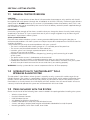
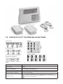
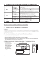
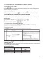
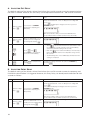
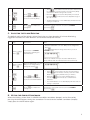
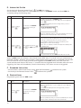
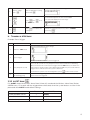
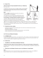
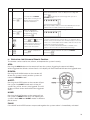
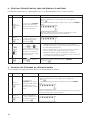
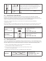
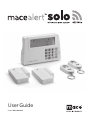
User Guide
Model: MAS-WA-SYS
CONTENTS
Section 1:
Getting started.......................................................................................................................................... 4
1.1
1.2
1.3
1.4
1.5
General system overview
Introduction to the system
Items included with the system
Introduction to the Wireless Alarm Panel
Introduction to the Panel Sound Alert & Backlight
Section 2:
Installing the Wireless Alarm System..............................................................................................6
2.1 Installing the Wireless Alarm Panel
2.2 Powering up the Wireless Alarm Panel
2.3 Understanding the battery and AC adaptor icon
Section 3:
Using the Wireless Alarm System.....................................................................................................8
3.1 Programming your 4-digit PIN
3.2 Transmitting an emergency (Panic) alarm
3.2.1 Using the Panic alarm
3.2.2 Using the Panic alarm without activating the siren
3.3 Operating different modes
3.3.1
3.3.2
3.3.3
3.3.4
STANDBY mode...................................................................................................................................................9
ARM mode
.....................................................................................................................................................9
A. Adjusting Exit Delay
B. Adjusting Entry Delay
C. Adjusting the Alarm Duration
D. Muting the Audible Countdown
E. Arming the system
F. Disarming the system
G. Zone settings
H. Triggers in ARM mode
ALERT mode ....................................................................................................................................................13
A. Entering the ALERT mode
B. Exiting the ALERT mode
C. Zone settings
HOME mode ....................................................................................................................................................15
A. Entering the HOME mode
B. Exiting the HOME mode
C. Zone settings
Section 4:
Installing the Sensors............................................................................................................................16
4.1 Introduction to the Sensors
4.2 Installing the Sensors
2
4.2.1 Installing the Door/Window Sensor
A. Powering up the Door/Window Sensor
B. Installing the Door/Window Sensor
C. Mounting with the double-sided adhesive pad
4.2.2 Installing the Motion Sensor
A. Powering up the Motion Sensor
B. Installing the Motion Sensor
C. Sensor sensitivity
D. Walk test
E. Mounting using screws
4.2.3 Introduction of Keychain Remote Control
A. Introduction
B. Operation
i.
Powering up the Keychain Remote Control
ii.
Enrolling the Remote Control onto the Wireless Alarm Panel
iii. Operating the Keychain Remote Control
iv. Deleting a Remote Control from the Wireless Alarm Panel
v.
Querying the ID Number of a Remote Control
4.3 House Security Code settings
4.4 Zone Code settings
Section 5:
Troubleshooting...................................................................................................................................... 22
5.1 FAQ
5.2 Troubleshooting
Section 6:
General Information.............................................................................................................................. 23
6.1 Product information
6.2 Specifications
6.2.1
6.2.2
6.2.3
6.2.4
Wireless Alarm Panel
Keychain Remote Control
Door/Window Sensor
Motion Sensor
6.3 Maintenance
6.4 Batteries
3
SECTION 1: GETTING STARTED
1.1 General System Overview
CAUTION!
The 9V battery in the Wireless Alarm Panel is for power back-up purposes only, and the unit should
be supplied with main power (through the AC adaptor) at all times. Difficulty in disarming the Wireless
Alarm Panel in ALARM mode may occur when it is powered by the back-up battery alone. This is not
a malfunction, and can be resolved by the use of a fresh 9V battery and main power supplied through
the included AC adaptor.
IMPORTANT!
Due to the signal strength of the alarm, we advise that you change the House Security Code settings
(explained in Section 4.3) if you suspect that one of your in-range neighbors may also be using the
MaceAlert™ Solo Wireless Alarm System.
Alarm system limitations
Even the most advanced alarm systems cannot guarantee 100% protection against burglary or
environmental problems. All alarm systems are subject to possible compromise or failure-to-warn for
a variety of reasons.
* Please note that you may encounter problems with your system if:
• The siren is not placed within hearing range or is in a remote part of the premises.
• The sensors are placed behind doors or other obstacles.
• Intruders gain access through unprotected points of entry
(where sensors are not located).
• Intruders have the technical means of bypassing, jamming, or disconnecting all or part
of the system.
• The power to the sensors is inadequate or disconnected.
• The sensors are not located in acceptable operating areas e.g. too close to a heat source.
• Inadequate maintenance is the most common cause of alarm failure. Therefore, test your system
at least once per month to ensure the sensors and siren(s) are working properly.
WARNING: Security system devices cannot compensate for loss of life or property.
1.2 Introduction to the MaceAlert™ Solo Wireless Alarm System
The MaceAlert™ Solo Wireless Alarm System is a quality security system with a wide range of userfriendly features. The system is controlled by a Wireless Alarm Panel, which gathers information from
wireless sensors placed inside and at the entry points of your home or office. If the Wireless Alarm
Panel detects a security breach, the LCD display will flash and the siren will sound. Details of how to
correctly install and operate the system are contained within this User Guide.
1.3 Items Included with the System
Please check that all of the following items were included in the package before installing the system:
•
•
•
•
•
•
•
4
Wireless Alarm Panel
Keychain Remote Controls
Door/Window Sensors
AC adaptor for Wireless Alarm Panel
Double-sided adhesive strips for Door/Window Sensors
Screws, wall plugs, tamper proof magnet with double-sided adhesive strip for panel
Mounting template, Quick Start Guide, User Guide
1.4 Introduction to the Wireless Alarm Panel
Keypad
LCD Screen:
Function Buttons:
Numeric Buttons
Programming Buttons:
Other:
9V DC INPUT port
For AC/DC adaptor
Siren output
120dB
Battery compartment:
For 9V Alkaline back-up battery
4 x Pin header, 4 x Jumper
For House Security Code setting
8 x Pin header, 1 x Jumper
For Zone Code setting
“RESET” button
If you forget the 4-digit PIN, press the “RESET” button located in the
battery compartment and enter factory default PIN “ 1–2–3–4 ” followed by
to restore factory settings.
5
1.5 Introduction to the Panel Sound Alert & Backlight
Operating Mode
1
2
Situation
Sound Alert and Backlight Indication
Zone triggered
under ARM status
Alarm duration: Adjustable between 1 – 6 minutes (siren).
Default is 1 minute
Panel — flashes RED every 1.5 seconds with triggered zone indicated
(to stop - enter 4-digit PIN and press
)
Alarm set under
ARM status
No siren.
Panel — flashes RED every 5 seconds providing an
intruder deterrent (different from when an intrusion occurs and the
panel rapidly and continuously flashes RED).
Zone triggered
under ARM status
Alarm duration: Adjustable between 1 – 6 minutes (siren).
Default is 1 minute
Panel — flashes RED every 1.5 seconds with triggered
zone indicated (to stop - enter 4-digit PIN and press
)
Zone triggered
under ALERT status
Sound output: Chime (ding-dong)
Panel — flashes GREEN every 1.5 seconds with triggered zone
indicated (to stop panel flashes-press
)
ARM
HOME
3
ALERT
Zone triggered
under ALERT status
Sound output: Chime (ding-dong)
Panel — flashes GREEN every 1.5 seconds with triggered zone
indicated (to stop panel flashes press
)
4
STANDBY
Silent
Panel — YELLOW backlight remains ON for 10 seconds
after entering into STANDBY mode
SECTION 2: INSTALLING THE Wireless Alarm System
2.1 Installing the Wireless Alarm Panel
WARNING:
The Wireless Alarm Panel has a built-in tamper proof switch to prevent the system being disabled by
an intruder. When fixing the Wireless Alarm Panel to a wall, first ensure that it is in STANDBY mode to
avoid the alarm sounding.
2.1.1 Locating the Wireless Alarm Panel & Tamper proof Switch
The Wireless Alarm Panel should be placed:
• Within a few feet of an electrical outlet
• Where it is easily accessible
• Away from doors or windows that could be accessed by intruders
• Away from extreme temperature sources (radiators, ovens, stoves etc.) and large metal objects
that could interfere with the wireless performance
2.1.2 Wall-Mounting the Wireless Alarm Panel & Tamper proof Switch
6
MAS-WA-SYS
84mm
MAS-WA-WDS
MAS-WA-MO
16mm
Mount tamperproof magnet here
43mm
• First cut out the
mounting template
for the Wireless
Alarm Panel along
with the area which
is marked out for
the position of
the tamper proof
magnet.
• Tape the template onto the wall, in the position you wish to install the Wireless Alarm Panel.
• Mark on the wall the points for drilling holes for the wall plugs and mounting screws, and the
position for mounting the tamper proof magnet.
• Drill the holes, insert wall plugs and locate the mounting screws for the Wireless Alarm Panel.
• Ensure the mounting surface for the tamper proof magnet is clean.
• Peel back one layer of the protective film on the double-sided adhesive strip and attach it to
the magnet.
• Peel back the remaining layer of protective film and press the magnet firmly in the marked
position against the mounting surface until firmly attached.
• Mount the Wireless Alarm Panel onto the wall.
• Once the Wireless Alarm Panel has been installed the system can be powered up.
The tamper proof system is enabled once the Wireless Alarm Panel is switched to HOME, ALERT
or ARM mode.
2.2 Powering up the Wireless Alarm Panel
Note: The Wireless Alarm Panel may have been supplied with an optional demonstration switch to show
the LCD display panel working while in its packaging. Before powering up the Wireless Alarm Panel, the
wire for this switch must be removed as described below (See Figs 1 & 2):
• Unscrew the battery compartment and remove the cover.
• Remove and discard the LED demo socket, if fitted (Fig.2)
• Insert a new back-up battery (noting the polarity) and plug the AC adaptor into the Wireless
Alarm Panel (Fig. 3)
• Replace the cover and screw, and connect the AC adaptor to a wall socket.(Fig. 4)
Step
Description
Note
One beep will sound and the backlight will blink within 1 second
(Yellow » Red » Green » Yellow)
The panel will display the below image:
1
Insert 9V Alkaline backup battery
The panel will enter “STANDBY” mode after the automatic selfwill appear on the LCD screen.
checking is complete. Then
Enter the default 4-digit PIN “1234”
2
Plug in AC adapter to the DC socket
in the back of the panel
The main power supply (with AC adaptor) must be
plugged in at all times. The 9V battery functions as a back-up
power supply only, when the main power supply is interrupted.
7
2.3 Understanding the Battery & AC Adaptor Icon
Battery icon shows
power status:
FULL
HIGH
MIDDLE
LOW
AC Adaptor icon
Battery icon shows when the AC power supply is unplugged or interrupted.
9V battery functions as BACK-UP only and the
symbol means LOW
BATTERY.
The LCD backlight flashes YELLOW for 30 seconds and
will blink until
the new battery is replaced or the mains power supply (with AC adaptor) is
plugged in.
When the AC adaptor to the Wireless Alarm Panel is connected to a wall
will appear.
socket, the AC symbol
The backlight will be ‘ON’ for 10 seconds while the AC adapter connects to
the power supply.
Section 3: Using The Wireless Alarm System
3.1 Programming your New 4-Digit PIN
The Wireless Alarm Panel is supplied with a default PIN of “1234”. This can be changed to your own
personalized PIN, or your own personalized PIN can be changed, as follows:
Keys
1
(1234 or 4-digit
PIN) +
Description
You must be in STANDBY
mode before programming
your new 4-digit PIN
Note
*To make sure you are in STANDBY mode:
- Enter the default PIN “ 1–2–3–4 ”
- Press
- The panel will display the image below when you are in
STANDBY mode:
(One beep indicates that you entered a valid PIN, three
beeps indicate that an invalid operation was performed).
The panel will display the below image:
2
(1234 or 4-digit
PIN) +
Enter the default PIN “ 1–2–3-4”
OR your new 4-digit PIN
followed by
- Press
then “1” to set the new PIN
- The panel will display the below image :
3
4
5
8
Press
followed by
New 4-digit PIN
+
Enter the new 4-digit PIN
followed by
New 4-digit PIN
+
Re-enter new PIN for
followed by
for final
confirmation
- LCD display
flashes with “1”
- Enter the new 4-digit PIN
- Press
to confirm
flashes with “2”
- LCD display
- Re-enter the new 4-digit PIN
for final confirmation
- Press
(One beep indicates that you entered a valid PIN, two
beeps indicate that an invalid operation was performed).
3.2 Transmitting an Emergency (Panic) Alarm
3.2.1 Using the Panic alarm
Pressing
&
buttons together on the Keypad or Keychain Remote Control will immediately
transmit an alarm signal to the Wireless Alarm Panel, activating the siren, and transmitting an alarm
signal to any optional response devices.
To disarm the Panic alarm
On the Wireless Alarm Panel: Enter your 4-digit PIN followed by
to exit from the Panic alarm.
On the Keychain Remote Control: Press
to exit from the Panic alarm.
3.2.2 Using the Panic Alarm without Activating the Siren
If you are forced to disarm the system, enter the Duress Password to stop the siren from sounding.
The Wireless Alarm Panel will then silently transmit an alarm signal to the optional response devices.
Duress Password:
Enter the default 4-digit PIN + “1” (
+
)+
OR
Enter your personalized 4-digit PIN +
+
3.3 Operating Different Modes
The system has 4 operating modes (STANDBY, ARM, ALERT, and HOME) to suit individual
requirements. These modes can be set as follows:
3.3.1 Standby Mode
If in STANDBY mode, the Wireless Alarm Panel is prepared for mode selection.
Keys
1
(1234 or 4-digit
PIN) +
Description
Note
You must be in STANDBY
mode before turning to
ARM mode
*To make sure you are in STANDBY mode:
- Enter the default PIN “ 1–2–3–4 ” OR your new 4-digit PIN
.
- Press
- The panel will display the below image while you are in
STANDBY mode:
(One beep indicates that you entered a valid PIN, three
beeps indicate that an invalid operation was performed).
3.3.2 ARM Mode
When in ARM mode, the Wireless Alarm Panel siren will sound and the panel display flashes RED every
1.5 seconds when the system is triggered.
ARM mode default setting:
Sensor
Zone
Status (MODE)
• Door/Window Sensor
1
ARM
• Door/Window Sensor
2
ARM
• Motion Sensor
8
ARM
9
A. Adjusting Exit Delay
The default setting of the Wireless Alarm Panel allows the user 20 seconds to exit the property before
the alarm is ARMED. However, this Exit Delay can be adjusted to between 10 — 60 seconds as follows:
Keys
1
(1234 or 4-digit
PIN) +
Description
Note
You must be in STANDBY
mode before adjusting the
Exit Delay
*To make sure you are in STANDBY mode:
- Enter the default PIN “ 1–2–3–4 ” OR your new 4-digit PIN
- Press
- The panel will display the image below when you are in
STANDBY mode:
(One beep indicates that you entered a valid PIN, three
beeps indicate that an invalid operation was performed).
2
(1234 or 4-digit
PIN) +
Enter the default PIN “ 1–2–3–
4” OR your new 4-digit PIN
for setting followed by
The panel will display the below image:
is pressed the first time the panel flashes with
• When
the number of seconds currently set for the Exit Delay
(The factory default setting is 20 seconds)
Press
then
(as many times as required)
to set the new Exit Delay
3
• Each time
is pressed the Exit Delay is increased by a
further 10 seconds between the adjustable range of 10 to
60 seconds
• The Exit Delay time on the LCD display will flash until the
setting is completed
Press
setting
4
to complete the
Confirm the setting and return the panel to STANDBY by
pressing
B. Adjusting Entry Delay
The default setting of the Wireless Alarm Panel allows the user 30 seconds to enter the property and
DISARM the alarm before it is triggered. However, this Entry Delay can be adjusted to between 10—60
seconds as follows:
Keys
1
(1234 or 4-digit
PIN) +
Description
You must be in STANDBY
mode before adjusting the
Entry Delay
Note
*To make sure you are in STANDBY mode:
- Enter the default PIN “ 1–2–3–4 ” OR your new 4-digit PIN
- Press
- The panel will display the image below when you are in
STANDBY mode:
(One beep indicates that you entered a valid PIN, three
beeps indicate that an invalid operation was performed).
2
10
(1234 or 4-digit
PIN) +
Enter the default PIN “ 1–2–3–
4” OR your new 4-digit PIN for
setting followed by
The panel will display the below image:
• When
is pressed the first time the panel flashes with
the number of seconds currently set for the Entry Delay
(The factory default setting is 30 seconds)
Press
then
(as many times as required)
to set the new Entry Delay
3
• Each time
is pressed the Entry Delay is increased
by a further 10 seconds between the adjustable range of
10 — 60 seconds
• The Entry Delay time on the LCD display will flash until the
setting is completed
Press
setting
4
to complete the
Confirm the setting and return the panel to STANDBY
by pressing
C. Adjusting the Alarm Duration
The default setting of the Wireless Alarm Panel gives an alarm duration of 1 minute after being
triggered. However, this alarm duration can be increased up to 6 minutes:
Keys
1
(1234 or 4-digit
PIN) +
Description
Note
You must be in STANDBY
mode before adjusting the
Alarm Duration
*To make sure you are in STANDBY mode:
- Enter the default PIN “ 1–2–3–4 ” OR your new 4-digit PIN
- Press
- The panel will display the image below when you are in
STANDBY mode:
(One beep indicates that you entered a valid PIN, three
beeps indicate that an invalid operation was performed).
2
(1234 or 4-digit
PIN) +
Enter the default PIN “ 1–2–3–4”
OR your new 4-digit PIN for
setting followed by
The panel will display the below image:
is pressed the first time the panel flashes
• When
with the number of minutes currently set for the Alarm
Duration (The factory default setting is 1 minute)
3
Press
then
(as many times as required)
to set the new Alarm Duration
• Each time
is pressed the alarm duration is
increased by a further minute up to a maximum of
6 minutes
• The Alarm Duration on the LCD display will flash until the
setting is completed
4
Press
setting
to complete the
Confirm the setting and return the panel to STANDBY
by pressing
D. Muting the Audible Countdown
When the Wireless Alarm Panel is ARMED the audible countdown (beeper) can be silenced by
pressing the MUTE button, during the countdown. To reactivate the audible countdown (beeper)
simply press the MUTE button again.
11
E. Arming the System
On the Keychain Remote Control: Press
to ARM the system.
On the Wireless Alarm Panel: First make sure the panel is in STANDBY mode, and then ARM the
system by taking the following steps:
Keys
1
(1234 or 4-digit
PIN) +
Description
You must be in STANDBY
mode before turning to
ARM mode
Note
*To make sure you are in STANDBY mode:
- Enter the default PIN “ 1–2–3–4 ” OR your new 4-digit PIN
.
- Press
- The panel will display the below image while you are in
STANDBY mode:
(One beep indicates that you entered a valid PIN, three beeps
indicate that an invalid operation was performed).
2
(1234 or 4-digit
PIN) +
+
Enter 4-digit PIN, press
and
for ARM mode
Exit delay: Up to 15 seconds
– There is a 15 second exit delay time with a visual and audible
(beeping) countdown before the system is armed.
(Press MUTE to disable the beeping countdown, press
MUTE again to resume the beeping)
– If the Zone is enabled, a number will appear as displayed in
the image below:
- The system will then enter ARM mode after 15 seconds.
When in ARM mode, the Wireless Alarm Panel flashes RED every 5 seconds, acting as a deterrent to
potential intruders. However, if an intruder is detected the panel continuously and rapidly flashes RED.
Once an intrusion has occurred (with the zone triggered under ARM status), the alarm siren will
sound and the panel flashes RED every 1.5 seconds with the triggered zone indicated. After the initial
triggering, the alarm will immediately sound, without delay, if any other sensors are triggered.
F. Disarming the system
• On the Wireless Alarm Panel: Enter your 4-digit PIN followed by
• On the Keychain Remote Control: Press
to disarm the system
to disarm the system.
G. Zone settings
Programming each zone in ARM mode:
Keys
1
(1234 or 4-digit
PIN) +
Description
You must be in STANDBY
mode before turning to
ARM mode
Note
*To make sure you are in STANDBY mode:
- Enter the default PIN “ 1–2–3–4 ” OR your new 4-digit PIN
.
- Press
- The panel will display the below image while you are in
STANDBY mode:
(One beep indicates that you entered a valid PIN, three beeps
indicate that an invalid operation was performed).
12
The panel will display the below image:
2
(1234 or 4-digit
PIN) +
Enter 4-digit PIN for setting
followed by
Press
then
the ARM mode
3
Press
setting
4
to set
to complete the
– Toggle 1, 2, 3, 4, 5, 6, 7, 8 to turn each zone ON or OFF
– If no number appears, the zone is turned OFF
– The panel will display the below image:
Confirm the setting and return the panel to STANDBY
by pressing
H. Triggers in ARM Mode
Example: Zone 1 trigger
Step
Description
Note
The panel will display the below image:
1
Under the “ARM” Mode
2
System trigger
One beep indicates that the system is triggered.
There are 30 seconds of entry delay time with a visual countdown for disarming.
3
Entry delay 30 seconds
Once an intrusion has occurred (zone triggered under ARM status), the alarm siren
will sound for 1 minute and the panel display flashes RED every 1.5 seconds with the
triggered zone indicated, until the system is disarmed.
4
Return to ARM mode after
the initial triggering
After the initial triggering, the alarm will immediately sound, without delay, if any
other sensors are triggered.
*To disarm the system, enter the 4-Digit PIN or press
on the remote control.
3.3.3 ALERT Mode
If in ALERT mode, the Wireless Alarm Panel chime will sound and the Wireless Alarm Panel flashes
GREEN every 1.5 seconds with the triggered zone indicated, when the system detects a visitor in the
protected area. ALERT mode default settings:
Sensor
Zone
Status (MODE)
• Door/Window Sensor
1
ALERT
• Door/Window Sensor
2
ALERT
• Motion Sensor
8
ALERT
13
A. Entering ALERT Mode
• On the Keychain Remote: Press
to activate.
• On the Wireless Alarm Panel: First make sure the panel is in STANDBY mode, and then enter into
ALERT mode by taking the following steps:
Keys
1
(1234 or
4-digit PIN) +
Description
Note
You must be in STANDBY
mode before turning to
ALERT mode
*To make sure you are in STANDBY mode:
- Enter the default PIN “ 1–2–3–4 ” OR your new 4-digit PIN
.
- Press
- The panel will display the below image while you are in
STANDBY mode:
(One beep indicates that you entered a valid PIN, three beeps
indicate that an invalid operation was performed).
2
(1234 or
4-digit PIN) +
+
Enter 4-digit PIN, press
and
for ALERT mode
- The system will then enter ALERT mode
- If the Zone is enabled, a number will appear as displayed in
the image below:
B. Exiting ALERT Mode
• On the Wireless Alarm Panel: Enter your 4-digit PIN followed by
• On the Keychain Remote Control: Press
to exit ALERT mode.
to exit ALERT mode.
C. Zone Settings
Programming each zone in ALERT mode:
Keys
1
(1234 or
4-digit PIN) +
Description
Note
You must be in STANDBY
mode before turning to
ALERT mode
*To make sure you are in STANDBY mode:
- Enter the default PIN “ 1–2–3–4 ” OR your new 4-digit PIN
- Press
.
- The panel displays the below image while in STANDBY mode:
(One beep indicates that you entered a valid PIN, three beeps
indicate that an invalid operation was performed).
The panel will display the below image:
2
4-digit PIN +
Enter 4-digit PIN for setting
followed by
(One beep indicates that you entered a valid PIN, three beeps
indicate that an invalid operation was performed).
3
Press
then
ALERT Mode
4
Press
setting
14
to set the
to complete the
Toggle 1, 2, 3, 4, 5, 6, 7, 8 to turn each zone ON or OFF
- If no number appears, the zone is turned OFF.
The panel will display the below image:
Confirm the setting and return the panel to STANDBY
by pressing
3.3.4 HOME Mode
There are default settings that allow the system to operate after opening the package. These settings
can be adjusted to suit your individual requirements The HOME mode allows the system operate in
both the ARM and ALERT modes in different zones.
HOME mode default setting:
Sensor
Zone
Status (MODE)
• Door/Window Sensor
1
ALERT
• Door/Window Sensor
2
ALERT
• Motion Sensor
8
ARM
A. Entering the HOME Mode
• On the Keychain Remote Control: Press
to activate.
• On the Wireless Alarm Panel: First make sure the panel is in STANDBY mode, and then enter HOME
mode by taking the following steps:
Keys
1
(1234 or 4-digit
PIN) +
Description
You must be in STANDBY
mode before turning to
HOME mode
Note
*To make sure you are in STANDBY mode:
- Enter the default PIN “ 1–2–3–4 ” OR your new 4-digit PIN
- Press
- The panel will display the below image while you are in
STANDBY mode:
(One beep indicates that you entered a valid PIN, three beeps
indicate that an invalid operation was performed).
2
4-digit PIN +
+
Enter 4-digit PIN, press
and
for HOME mode
- Then system will enter HOME mode
- If the Zone is enabled, a number will appear as displayed in the
image below:
B. Exiting the HOME Mode
• On the Wireless Alarm Panel: Enter your 4-digit PIN followed by
• On the Keychain Remote Control: Press
to exit HOME mode.
to exit HOME mode.
C. Zone Settings
Programming each zone in HOME mode:
Keys
1
(1234 or 4-digit
PIN) +
Description
You must be in STANDBY
mode before turning to
HOME mode
Note
*To make sure you are in STANDBY mode:
- Enter the default PIN “ 1–2–3–4 ” OR your new 4-digit PIN
- Press
- The panel will display the below image while you are in
STANDBY mode:
(One beep indicates that you entered a valid PIN, three beeps
indicate that an invalid operation was performed).
15
The panel will display the below image:
2
4-digit PIN +
Enter 4-digit PIN for
setting followed by
(One beep indicates that you entered a valid PIN, three beeps
indicate that an invalid operation was performed).
Toggle 1, 2, 3, 4, 5, 6, 7, 8 to turn each zone in different mode
Indicates ALERT mode for a zone
Indicates ARM mode for a zone
3
Press
then
the HOME mode
to set
4
Press
to complete
the setting
Indicates the zone is turned OFF, number will not appear
The panel will display the below image:
Confirm the setting and return the panel to STANDBY
by pressing
SECTION 4: INSTALLING THE SENSORS
4.1 Introduction to the Sensors
This package includes 2 wireless sensors which have a pre-programmed default setting that begins
working immediately once the battery is activated (the Keychain Remote Control needs to be enrolled
onto the system before it can operate – see Section 4.2.3). It is advisable to install the main package
first and then personalize the settings once the system is functioning properly. This section should
help you to change the system settings in order to create a more personal home environment.
4.2 Installing the Sensors
First, determine the location of the sensors.
*Note: The sensors should be placed:
• Where they are not easily accessible.
• In the most vulnerable rooms or near key entry points.
• Away from extreme temperature sources (radiators, ovens, stoves etc.) and large metal objects
that could interfere with the wireless performance.
• Where better RF performance can be achieved (if necessary).
Once you have selected a location for the sensors, the system can be powered up.
4.2.1 Installing the Door/Window Sensors
The Door/Window Sensors consists of two parts, a transmitter and a magnet. Once the sensors are
installed, and the two parts are fastened onto the door or window, the sensor will trigger and transmit
a message to the Wireless Alarm Panel when the door or window is opened. One Door/Window
Sensor is pre-programmed in Zone 1 and the other one is set in Zone 2; however, these settings can be
adjusted according to your requirements. (See 3.3 & 4.4 Zone Settings)
16
A. Powering up the Door/Window Sensors
• Remove the battery cover; insert new batteries noting the polarity
as shown in the diagram below and replace the cover.
(Requires 2 x AAA batteries)
• Low battery indication: If the batteries need to be replaced,
the RED LED on the transmitter will flash slowly.
B. Installing the Door/Window Sensors
• Mount the transmitter on a fixed surface such as a door
or a window frame.
• Mount the magnet on a movable surface such as a door or a window.
• Ensure the >|< marks on the sides of the transmitter and magnet match
up as shown in the diagram.
• The transmitter and the magnet must be no more than 5mm apart
C. Mounting with the Double-Sided Adhesive Pad
• Ensure the mounting surface is clean.
• Peel back one layer of the protective film and attach it to the transmitter.
• Peel back the remaining layer of protective film and press the transmitter firmly in place against
the mounting surface until firmly attached.
• Repeat to attach the magnet.
4.2.2 Installing the Motion Sensor (optional accessory)
The Motion Sensor is designed to sense movement in a given area.
Note: It is best if pets are not allowed onto higher surfaces so that the
sensors are not triggered unnecessarily (no more than 3 feet high).
A. Powering up the Motion Sensor
• Remove the battery cover, insert and connect a 9V battery as shown in
diagram below and replace the cover. (Requires 1 x 9V battery)
• Low battery indication: If the batteries need to be replaced, the RED LED will flash
(not including entry/exit delay flashing).
B. Installing the Motion Sensor
First, determine the location of the Motion Sensor.
*Note: The Sensor should be placed:
• In the most vulnerable rooms or near key entry points.
• On a solid surface between 6 ft to 8 ft (1.8m to 2.4m) from the floor.
• Away from extreme temperature sources (radiators, ovens, stoves etc.)
• Away from direct sunlight.
• Indoors only and not behind partitions
• Where better RF performance can be achieved (if necessary)
C. Sensor Sensitivity
IMPORTANT!
The Motion Sensor is designed with a power saving program and will remain inactive for 3 minutes
after each detection. Please bear this in mind during system set up.
The sensitivity of the Motion sensor is adjustable and can be changed by setting the connector, found
in the battery compartment, on either the ‘High’, ‘Middle’ or ‘Low’ position. When the sensitivity is set
to “Low”, more movement is required to trigger the sensor. It is recommended to set the sensitivity
to “Low” and perform a “Walk Test” (Described in part D). If the walk test result is satisfactory, the
sensitivity does not require further adjustment. If the walk test result shows the sensitivity is too low,
then the sensitivity can be set to “Middle” or “High” as required. It is recommended that a walk test be
conducted after each change in sensitivity setting.
17
D. Walk Test
After mounting the sensor at the desired location, it is important to
perform a walk test in order to determine if the sensor is detecting
the correct area.
The distance at which the sensor can detect motion can be adjusted
by altering the angle of the sensor. To reduce the detection range,
simply move the sensor downward and move the sensor upward to
maximize the range.
Note:
Enter into ALERT mode before you perform the walk test,
so that the alarm is not triggered.
You should walk in the area that you would like the sensor
to monitor. If movement is detected the red light inside the
unit will appear. If the red light does not appear, adjust the
mounting angle accordingly. Perform the walk test again after
3 minutes. Repeat this procedure until motion is detected.
While you are carrying out the test, there should be no
movement in the detection area during the 3 minute interval.
*Tip: The sensor should not face towards direct sunlight, be placed near heat or cold producing
devices (i.e. air conditioning, radiators, fans, ovens, heaters etc.) that may cause false triggers.
Also perform the walk test in areas where the sensor is not intended to cover, to ensure movement
cannot be detected.
E. Mounting using screws
• Hold the enclosed mounting template against the wall at the selected location and mark
the points for drilling.
• Drill the holes and insert wall plugs.
• Attach the bracket to the mounting surface with the screws provided.
• Attach the Motion Sensor to the mounting bracket.
4.2.3 Keychain Remote Control
A. Introduction
The Keychain Remote Control allows you to operate the systems Wireless Alarm Panel remotely, from
inside or outside the property. Using the control the system can be armed or disarmed and the siren
can be activated instantly if required (using the Panic function).
B. Operation
i.
Powering up the Keychain Remote Control
The Remote Control includes a 12V alkaline battery. To activate, unscrew and remove the back of the
Remote Control, and carefully remove the clear plastic insulation tab from the battery. If the battery is
dislodged, replace it noting the correct polarity as shown inside the battery compartment. Replace the
battery cover.
ii. Enrolling the Remote Control onto the Wireless Alarm Panel
Note:
Before being able to use the Keychain Remote Control supplied with the system, or any additional
Remote Controls, they first need to be enrolled (added onto the system) as follows:
18
Keys
1
(1234 or 4-digit
PIN) +
Description
Note
You must be in STANDBY
mode before enrolling a new
Remote Control onto the
Wireless Alarm Panel
*To make sure you are in STANDBY mode:
- Enter the default PIN “ 1–2–3–4 ” OR your new 4-digit PIN
- Press
- The panel will display the below image while you are in
STANDBY mode:
(One beep indicates that you entered a valid PIN, three beeps
indicate that an invalid operation was performed).
2
(1234 or 4-digit
PIN) +
3
4
Enter the default PIN
“ 1–2–3–4 ” OR your new
4-digit PIN for setting
followed by
Press
then
to enter
the Remote Control Enroll
mode. Then press any key on
the new Remote Control to
enroll it onto the system.
Press
setting
to complete the
The panel will display the below image:
LCD display flashes the ID no. of the remote to be enrolled
e.g. when enrolling the first remote ID no. “01” will flash. Once
the first remote is enrolled the “02” will flash ready for a second
remote to be enrolled (One beep indicates that the remote was
enrolled to the panel successfully)
Note: It is recommended that the ID No. is marked on the
remote in case it needs to be deleted at a later stage
Confirm the setting and return the panel to STANDBY
by pressing
iii. Operating the Keychain Remote Control
The remote can be used to arm, disarm, and operate the system instantly.
ARM:
Pressing the ARM button on the remote will arm the system, triggering the preset exit delay.
When triggered the Wireless Alarm Panel’s LCD display will flash Red and indicate the triggered zone.
DISARM:
Pressing the DISARM button on the remote will
disarm the system instantly and the system will
return to Standby mode.
ALERT:
Pressing the ALERT button on the remote will put
the system into Alert mode and a chime will
sound if any of the sensors are triggered. The LCD
display will flash Green and indicate the triggered
zone.
HOME:
Pressing the HOME button on the remote will set
the system in Home mode which will operate the
system in both Arm and Alert modes in different
preset zones.
PANIC:
If the HOME and ALERT buttons are pressed together the systems alarm is immediately activated.
19
iv. Deleting a Remote Control from the Wireless Alarm Panel
If a Remote Control device is damaged or lost, it can be deleted from the system as follows:
Keys
1
(1234 or
4-digit PIN) +
Description
You must be in STANDBY
mode before deleting a
Remote Control from the
Wireless Alarm Panel
Note
*To make sure you are in STANDBY mode:
- Enter the default PIN “ 1–2–3–4 ” OR your new 4-digit PIN
- Press
- The panel will display the below image while you are in STANDBY
mode:
(One beep indicates that you entered a valid PIN, three beeps
indicate that an invalid operation was performed).
2
(1234 or
4-digit PIN) +
Enter the default PIN
“ 1–2–3–4 ” OR your new
4-digit PIN for setting
followed by
Press
then
to
enter the Remote Control
Deleting mode. Then input
the ID no. of the Remote
Control you wish to delete
from the system
3
Press
to complete
the setting
4
The panel will display the below image:
• LCD display flashes the total number of remote currently
enrolled to the system (e.g. If the panel has 3 remotes enrolled
the LCD display will flash “03”)
• Input the remote ID no. (e.g. “02”) for the remote you wish to
delete (Inputting “00” will delete all remote controls)
• LCD display will then flash the total number of remotes
enrolled after deletion(One beep indicates that the remote was
successfully deleted from the panel)
Confirm the setting and return the panel to STANDBY
by pressing
v. Querying the ID Number of a Remote Control
The ID number of a Remote Control device can be identified as follows:
Keys
1
(1234 or
4-digit PIN) +
Description
You must be in
STANDBY mode before
querying the ID number
of a Remote Control
from the Wireless Alarm
Panel
Note
*To make sure you are in STANDBY mode:
- Enter the default PIN “ 1–2–3–4 ” OR your new 4-digit PIN
- Press
- The panel will display the below image while you are in STANDBY
mode:
(One beep indicates that you entered a valid PIN, three beeps indicate
that an invalid operation was performed).
2
20
(1234 or
4-digit PIN) +
Enter the default PIN
“ 1–2–3–4 ” OR your new
4-digit PIN for setting
followed by
The panel will display the below image:
Press
then
to go into Remote
Querying mode, and
then press any key on
the remote to check
its ID.
3
Press
the query
4
4.3
to complete
- After entering into Remote Querying mode, the LCD display
will flash the total number of remote controls currently enrolled to the
system (e.g. If 3 remotes are enrolled the LCD display will flash “03”)
- The ID No. of the Remote can then be checked by pressing
any key on the remote (e.g, if the LCD display flashes “02”
then that is the ID of the remote)
Complete the query and return the panel to STANDBY by pressing
House Security Code Settings
In most cases the factory settings of the House Security Code will NOT need to be changed.
However, if the Wireless Alarm Panel and Sensors activate intermittently or do not work at all, this
may be due to interference with other systems, which can be avoided by changing the House Security
Code. To change this code, take the following steps with each system module:
1. There are 4 Jumpers/Dip-switches on each device. To locate these remove the battery
compartment cover.
2. Set the Jumpers as shown below (Push in for ON / Pull out for OFF) to change the House Security
Code setting. Make sure the Jumper/Dip-switch settings on all devices match each other exactly.
ON = Pushed in; OFF = Pulled out
Jumpers:
House Security Code
Dip-switches:
House Security Code
4.4
– Wireless Alarm Panel
– Sensors
Default Code:
1: ON, 2: ON, 3: ON, 4: ON
– Keychain Remote Controls
Default Code:
1: ON, 2: ON, 3: ON, 4: ON
Zone Code Settings
Sensors are supplied with pre-assigned Zone settings to make setup easy – the Door/Window Sensors
are pre-assigned to Zones 1 & 2 and the Motion Sensor to Zone 8. To assign a Sensor to a different zone,
the Zone Code on the Sensor needs to be changed. To change this code, take the following steps:
1.There is a Zone Code Jumper on each Sensor which can be located
by removing the Jumper compartment cover.
2.Then pull out the Jumper and reassign it to the new Zone (Zones 1 to 8)
as shown in the diagram below.
3.Replace and screw back the cover to complete the Zone Code setting.
Jumper for
Zone Code
Default zone code:
Door/Window sensor – Zone 1
Door/Window sensor – Zone 2
Motion sensor – Zone 8
21
SECTION 5: TROUBLESHOOTING
5.1 FAQs
Q1: What is the best way to set up my system? Where should I put my Wireless Alarm Panel and the sensors?
A1: We recommend that you take some time in advance to think about the placement of the
Wireless Alarm Panel and Sensors. The best location for the panel is usually by the main entry/
exit point, in a hallway, or in another central location in your home. However, it must be plugged
into a power socket, which may dictate where it can be placed.
*Please note that the alarm is pre-programmed with default settings, allowing you a predetermined amount of time to enter (30 seconds) and time to exit (20 seconds) before the alarm
sounds. You can either change the default delay setting to allow more time to enter/exit your
home or, alternatively use the Keychain Remote Control to disarm the system.
Q2: How many Sensors can the Wireless Alarm Panel support?
A2. An unlimited number of sensors can be supported by the system, added to different zones in
your house, as you see fit.
Q3: What wireless range should I expect from Sensors?
A3: The range will vary depending on the type of structure; however, in an open space, the sensors
should be capable of transmitting a signal up to 450 feet from the panel. Determine the location
of the sensors first and change to a different location for better RF performance.
Q4:How do I attach my Sensors?
A4: Adhesive tape and screws are provided for the purpose of securely mounting these items.
Please refer to the User Guide for more information about mounting the Wireless Alarm Panel
and the wireless sensors.
Q5: Do I have to program the Wireless Alarm Panel?
A5: The system is designed for easy installation. This means that the wireless sensors are in a default
setting already registered to the panel and will therefore function immediately after the sensors
are powered up. If you choose to buy additional accessories, these will need to be added to your
system using the easy to follow instructions.
*Note: Due to the strong signal of the alarm, we advise that you change the House Security Code
settings following section 4.3 of this manual, if you suspect that one of your in-range neighbors
may also be using this alarm system.
Q6: Can I still use the same system if I move?
A6. The system is completely portable. If you move, you can remove your panel and wireless
accessories and re-install them in your new property.
Q7: What if I forget my PIN?
A7: If you forget your PIN, you may press the [ Reset ] button inside the battery compartment of the
Wireless Alarm Panel and the PIN will be reset to the factory default PIN 1234.
Q8: Why does my Motion Sensor not respond to movement?
A8: Motion Sensors are very sensitive so to preserve battery life the sensor will go to “Sleep” after
an event has been identified and reported to the panel. This “Sleep” period lasts 3 minutes, after
which, if no activity is detected, the Motion Sensor will again become active and ready to detect
other events.
Q9: Why does my Motion Sensor keep generating false alarms?
A9: If you have a pet, make sure they have not triggered the system. Remember, sensitivity to pets
increases in certain circumstances (e.g. the nearer the pet gets to the Sensor)
22
5.2 Troubleshooting
AC power failure:
This may occur if your security system is accidentally unplugged or if there has been a main power
cut. If a full power failure occurs, please contact your electric company to find out the source of the
problem. The back-up battery will continue to run the system for approximately 6 hours.
System battery failure:
This may occur if the emergency back-up battery has been drained and needs to be replaced. If AC
power is not restored, the low battery symbol will flash indicating that the panel back-up battery is
running low. The back-up battery should be replaced once the low battery symbol appears.
Sensor failure:
This may occur if a sensor is not communicating with the panel. It is necessary for you to ensure the
House Security Code dip-switch and jumpers of the sensors are set correctly to the panel.
SECTION 6: GENERAL INFORMATION
6.1 Product Information
Wireless systems are reliable and tested to high standards; however, it is important to consider
that there are some limitations due to their transmitting power and range:
– Receivers may be blocked by radio signals occurring on or near operating frequencies,
regardless of the code selected.
– A receiver can only respond to one transmitted signal at a time.
– Wireless equipment should be tested regularly to determine whether there are sources
of interference and to protect against faults.
6.2 Specifications
6.2.1 Wireless Alarm Panel
Power source:............................................................................................. AC adaptor
Back up power:.......................................................................................... 9V alkaline battery x 1
Sensor numbers:....................................................................................... Unlimited
House Code:................................................................................................ 4 Jumpers
Operating frequencies:........................................................................... 433.92 MHz +/-0.5 MHz
Siren output::............................................................................................... 120dB (Duration-adjustable)
6.2.2 Keychain Remote Control
Power source:............................................................................................. 12V alkaline battery x 1
RF working transmission frequency:................................................ 433.92 MHz +/-0.5 MHz
House Code:................................................................................................ 4 Jumpers
Wireless range to Wireless Alarm Panel:....................................... < 200 feet (open area)
6.2.3 Door/Window Sensor
Power source:............................................................................................. AAA alkaline battery 1.5V x 2
RF working transmission frequency:................................................ 433.92 MHz +/-0.5 MHz
House Code:................................................................................................ 4 Jumpers
Zone Code: Pin header:.......................................................................... 8 pin
Wireless range to Wireless Alarm Panel:....................................... < 450 feet (open area)
23
6.2.4 Motion Sensor
Power source:............................................................................................. 9V alkaline battery x 1
RF working transmission frequency:................................................ 433.92 MHz +/-0.5 MHz
PIR detection angle:................................................................................. < 120˚
PIR detection range:................................................................................ H: < 49 ft, M: < 19.5 ft, L: < 13 ft
House Code:................................................................................................ 4 Jumpers
Zone Code:.................................................................................................. Pin header: 8 pin
Wireless range to Wireless Alarm Panel:....................................... < 450 feet (open area)
Power saving timer:................................................................................. 3 minutes
6.3 Maintenance
The product may be cleaned with a soft damp cloth and then wiped dry. Do not use abrasive, solventbased or aerosol cleaners as this may damage and/or discolor the product. Do not allow water to
enter or attempt to clean the inside of the unit.
6.4 Batteries
—Do not allow batteries to corrode and leak as this may cause permanent
damage to the product.
—Take care to insert the batteries with the correct polarity as shown inside
the battery compartments.
—Do not mix new and old batteries or different types of batteries.
—Do not use rechargeable batteries.
—At the end of their useful life the batteries should be disposed of via a suitable Recycling Center.
Do not dispose of with your normal household waste.
DO NOT BURN.
WARNING—Risk of Personal Injury Prolonged exposure to alarm siren may cause permanent hearing damage or loss.
FCC COMPLIANCE
This device complies with Part 15 of the FCC Rules. Operation is subject to the following two conditions:
(1) This device may not cause harmful interference. (2) This device must accept any interference received including interference that may cause undesired operation.
* Federal Communications Commission (FCC) Statement
WARNING: This equipment has been tested and found to comply with the limits for a Class B digital device, pursuant to Part 15 of the FCC rules. These limits are designed
to provide reasonable protection against harmful interference in a residential installation. This equipment generates uses and can radiate radio frequency energy and, if not
installed and used in accordance with the instructions, may cause harmful interference to radio communications. However, there is no guarantee that interference will not occur
in a particular installation. If this equipment does cause harmful interference to radio or television reception, which can be determined by turning the equipment off and on, the
user is encouraged to try to correct the interference by one or more of the following measures: — Reorient or relocate the receiving antenna. — Increase the separation between
the equipment and receiver. — Connect the equipment into an outlet on a circuit different from that to which the receiver is connected. — Consult the dealer or an experienced
radio/TV technician for help.
* You are cautioned that changes or modifications not expressly approved by the party responsible for compliance could void your authority to operate the equipment.
12-MONTH WARRANTY
For additional information visit: www.mace.com
24