1
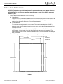
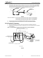
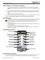
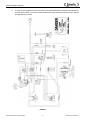
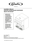
UC100 Installation Manual
INSTALLATION MANUAL
Starbucks UC100 Progate Ice Dispenser
DESCRIPTION
The UC100 Progate ice dispenser solves your ice service needs in a sanitary, space saving, economical
way. Designed to be manually filled with Ice-O-Matic half cube ice.
CAUTION: The dispenser cannot be used with crushed or flaked ice. Use of bagged ice
which has frozen into large chunks can void warranty. The dispenser agitator is not
designed to be an ice crusher. Use of large chunks of ice which “jam up” inside the hopper
will cause failure of the agitator motor and damage to the hopper.
Specifications
Model:
Ice Storage:
Electrical:
CO2 or Air Requirements:
Dimensions:
Release Date: January 24, 2008
© 2008, IMI Cornelius Inc.
UC100 Progate
100 lbs
120/1/60, 3 amps total unit draw
100 psi max to unit regulated to 50 psi (3.4 bar) to Progate ice gate system
24” Wide
30” Deep
27” Below Countertop
28” Above Countertop
www.cornelius.com
-1-
Revision: A
Publication Number: 621054211INS
UC100 Installation Manual
SAFETY INSTRUCTIONS
Read and Follow all Safety Instructions
Read and follow all safety instructions in this manual and on the machine (decals, labels, and laminated
cards). Read and understand all applicable OSHA (Occupation Safety and Health Administration) safety
regulations before operating the machine.
Recognize Safety Alerts
This is the safety alert symbol. When you see it in this manual or on the machine be
alert to the potential of personal injury or damage to the machine.
Different Types of Alerts
There are 3 types of safety alerts:
DANGER — Indicates an immediate hazardous situation which if not avoided WILL result in
serious injury, death, or equipment damage.
WARNING — Indicates a potentially hazardous situation which, if not avoided, COULD result in
serious injury, death, or equipment damage.
CAUTION — Indicates a potentially hazardous situation which, if not avoided, MAY result in
minor or moderate injury or equipment damage.
Safety Tips
•
•
•
•
Carefully read all safety messages in this manual and safety signs on the machine.
Keep safety signs in good condition and replace missing or damaged safety signs.
Learn how to operate the machine and how to use the controls properly.
Do not let anyone operate the machine without proper training. This appliance is not intended for use
by very young children or infirm persons without supervision. Young children should be supervised to
ensure that they do not play with the appliance.
• Keep your machine in proper working condition and do not allow unauthorized modifications to the
machine.
Qualified Service Personnel
CAUTION — Only trained and certified electrical, plumbing and refrigeration technicians should
service this unit. ALL WIRING AND PLUMBING MUST CONFORM TO NATIONAL AND LOCAL
CODES.
CO2 (Carbon Dioxide) Warning
WARNING — CO2 Displaces Oxygen. Strict Attention must be observed in the prevention of
CO2 gas leaks in the entire CO2 and soft drink system. If a CO2 gas leak is suspected, particularly
in a small area, immediately ventilate the contaminated area before attempting to repair the leak.
Personnel exposed to high concentration of CO2 gas will experience tremors which are followed
rapidly by loss of consciousness.
Publication Number: 621054211INS
-2-
© 2008, IMI Cornelius Inc.
UC100 Installation Manual
SAFETY PRECAUTIONS
This ice dispenser has been specifically designed to provide protection against personal injury and
eliminate contamination of ice. To ensure continued protection and sanitation, observe the following:
IMPORTANT: Disconnect power to the dispenser before servicing or cleaning.
NEVER: place hands inside of hopper or gate area without disconnecting power to the dispenser.
Agitator rotation occurs automatically when dispenser is energized!
ALWAYS: be sure the removable lid is properly installed to prevent unauthorized access to the hopper
interior and possible contamination of the ice.
ALWAYS: be sure the upper and lower front panels are securely fastened.
ALWAYS: keep area around the dispenser clean of ice cubes.
© 2008, IMI Cornelius Inc.
-3-
Publication Number: 621054211INS
UC100 Installation Manual
INSTALLATION INSTRUCTIONS
IMPORTANT: It is the responsibility of the Installer to ensure that the water supply to the
dispensing equipment is provided with protection against backflow by an air gap as defined in
ANSI/ASME A112. 1.2–1979; or an approved vacuum breaker or other such method as proved
effective by test.
1.
2.
Locate the dispenser indoors on a level counter top.
A. Caster Option
Unpack the four (4) casters and install them into the threaded holes provided in the bottom of the
unit. The installer must provide flexibility in the product and utility supply to permit shifting the
position of the dispenser sufficiently to clean the area beneath it.
B. Counter Mounting
The ice dispenser must be sealed to the counter. The mounting template (see FIGURE 1)
indicates where openings can be cut in the counter. Locate the desired position for the
dispenser, then mark the outline dimensions on the counter using the template drawings. Cut
openings in counter.
Apply a continuous bead of NSF International (NSF) silastic sealant (Dow 732 or equal)
approximately 1/4-inch inside of the unit outline dimensions and around all openings. Then,
position the unit on the counter within the outline dimensions. All excess sealant must be wiped
away immediately.
The drain lines, power cord and air supply are routed through the openings in the bottom of the unit.
24
UNIT FOOT PRINT
22 1/2
CUT OUT
30
UNIT FOOT PRINT
2 1/2
CLEARANCE
NEEDED FOR
OPENING LID
29
CUT OUT
THIS FIGURE SHOWS THE REQUIRED CUTOUT FOR PLACING THE ICE DISPENSER INTO A COUNTER TOP.
THE SOLID LINE IS THE ACTUAL CUTOUT DIMENSIONS WHILE THE DASHED LINE SHOWS THE UNIT FOOT PRINT
FIGURE 1
Publication Number: 621054211INS
-4-
© 2008, IMI Cornelius Inc.
UC100 Installation Manual
3.
The dispenser drain lines must slope a minimum of 1/4” per foot to the floor drain, see FIGURE 2.
Drain lines must be installed to comply with federal, state and local codes. It is required to fully
insulate all drain lines and fittings to prevent condensation from forming!!!
Dispenser
Drain Point
Drain Line
Horizontal
Reference Line
1/4”
1’
Floor Drain
FIGURE 2
If the unit is installed in a: 36” tall counter top, the floor drain must be within 23’ of the dispenser.
34” tall counter top, the floor drain must be within 15’ of the dispenser.
30” tall counter top, the floor drain must be within 1’ of the dispenser.
4.
5.
Clean the hopper interior (see CLEANING INSTRUCTIONS in Operator’s Manual).
Connect the power cord to a 120 volt, 60 cycle, 15–Amp, 3–wire grounded receptacle.
Set Up Supplied Air Compressor
1.
2.
Set up and install the air compressor, follow the manufacturer’s installation instructions.
Route the 1/4” beverage tube from the air compressor to the air valve solenoid inlet tube connector
on the dispenser.
NOTE: The filter/regulator is preset to 50 psi and should not require adjustment.
FILTER/REGULATOR ASSEMBLY
PRESET TO 50 PSI, NO ADJUSTMENT NEEDED
E-BOX
AIR VALVE SOLENOID
CLEAR TUBE
CUSTOMER CONNECTION
INCOMING SUPPLY SHOULD BE
SET TO 100 PSI
AIR CYLINDER
(LOCATED IN
TOWER CLADDING)
1/4" TUBE WHIP
(SUPPLIED WITH UNIT)
CLEAR RED TUBE
AIR SCHEMATIC
FIGURE 3
© 2008, IMI Cornelius Inc.
-5-
Publication Number: 621054211INS
UC100 Installation Manual
Adjust Carbonator CO2 Regulator (if applicable)
CAUTION: Before connecting the CO2 regulator assembly to a CO2 cylinder, turn the regulator
adjusting screw to the left (counterclockwise) until all tension is relieved from the adjusting screw
spring.
1.
2.
Open (counterclockwise) CO2 cylinder valve slightly to allow lines to slowly fill with gas, then open
the valve fully to back-seat the valve. (Back-seating the valve prevents leakage around the valve
shaft).
The CO2 regulator is fixed at a nominal 100 psi.
3.
Route the 1/4” beverage tube from the CO2 regulator to the air valve solenoid inlet tube connection.
NOTE: The filter/regulator is preset to 50 psi and should not require adjustment.
UNIT OPERATION
WARNING: The unit must be electrically grounded to avoid possible fatal electrical shock or serious
injury to the operator. The unit power cord is equipped with a three-prong plug. If a three-hole
(grounded) electrical outlet is not available, use an approved method to ground the unit.
1.
2.
3.
4.
Fill the hopper with ice.
Connect electrical power to the dispenser. The dispenser will enter the Prime mode and fill the ice
chute completely full.
Check for air and CO2 leaks and tighten any loose connections.
Push one of the “V” buttons on the keypad to dispense a large (Venti) cup of ice. This ensures the
ice chute is completely full.
Keypad Button Description
Information Display
Green dot indicates
unit power is ON
“Shaken” product ice
portion side of keypad
“Blended” product ice
portion side of keypad
Blended Short ice
portion button
Shaken Short ice
portion button
Shaken Tall ice
portion button
Blended Tall ice
portion button
Shaken Grande
ice portion button
Blended Grande ice
portion button
Shaken Venti ice
portion button
Blended Venti ice
portion button
Manual Dispense Button
Programming Button
FIGURE 4
Keypad Function Description
Just above the keypad is an information display that will show a code 2 through 4 letter. This code is to
notify the user the status/error of the dispenser. Listed below are the codes and their meaning:
Publication Number: 621054211INS
-6-
© 2008, IMI Cornelius Inc.
UC100 Installation Manual
PR (Prime) - This code will display when the unit has just been powered.
ICE - When displayed, ice levels are low or close to empty inside the hopper.
LOC (Lock) - When displayed, check to make sure that ice bin covers, ice chute transition, piece ice
flapper and ice chute are attached properly. Once secured, push the “M” button on the keypad to return to
dispense mode.
FILL - When displayed, all ice has been consumed and needs to be replaced. Refill the ice bin. Close all
ice bin covers and push the “M” button on the keypad to return to dispense mode.
ERR (Error) - When displayed, a system fault has occurred. Push the “M” button on the keypad to reset
the dispenser and return to dispense mode.
START-UP AND OPERATING INSTRUCTIONS
Fill the hopper with ice and then push one of the “V” buttons on the keypad to dispense a large cup of ice.
Repeat this procedure every time the dispenser has run out of ice. Dispense a large cup of ice. Repeat
this procedure whenever the dispenser has run out of ice. This insures that the ice chute is completely
filled before use.
CAUTION: Use caution to avoid spilling ice when filling the dispenser. Clean up any spilled
ice immediately. To prevent contamination of ice, the lid must be installed on the unit at all
times.
If the dispenser fails to dispense ice, see troubleshooting guide.
Programming the Ice Weight Portion
The ice weight portion setting is factory set for each portion size or keypad button. Follow the instructions
below to increase or decrease the amount of ice dispensed for a portion size.
1.
Press P and Blended Short (S) buttons simultaneously until SIZE displays on the information
display.
2.
Press and hold the desired size you wish to program until corresponding green LED flashes.
NOTE: The information display will now show the current value (in milliseconds) of that portion
size.
3.
4.
Press the up or down button to increase/decrease the duration of dispense. Each press will
increase/decrease the duration by 5ms.
Press the corresponding size button currently being programed until the green LED stops flashing.
© 2008, IMI Cornelius Inc.
-7-
Publication Number: 621054211INS
UC100 Installation Manual
5.
To save the new programmed size, press the P and the Blended Short (S) buttons simultaneously
until the screen clears. If no action is taken within 60 seconds, dispense mode will resume and any
changes will not be saved.
FIGURE 5
Publication Number: 621054211INS
-8-
© 2008, IMI Cornelius Inc.
UC100 Installation Manual
TROUBLESHOOTING
IMPORTANT: Only qualified personnel should service internal components or electrical wiring.
WARNING: If repairs are to be made to the CO2 or air system, stop dispensing, shut off the
CO2 or air supply, then relieve the system pressure before proceeding. If repairs are to be
made to the ice dispensing system, make sure electrical power is disconnected from the
unit.
Trouble
Probable Cause
Remedy
NOTE: Should your unit fail to operate properly, check that there is power to the unit and that the
hopper contains ice. If the unit does not dispense, check the following chart under the appropriate
symptom(s) to aid in locating the defect.
BLOWN FUSE OR
A. Short circuit in wiring (115V circuit).
A. Contact service agent.
CIRCUIT BREAKER.
B. Defective agitator motor.
B. Contact service agent.
SLUSHY ICE. WATER IN A. Blocked drain.
A. Open-up/flush out drain.
HOPPER
B. Unit not level.
B. Level unit.
C. Poor ice quality due to water quality or C. Contact service agent. For Icemaker
ice maker problems.
problems, consult icemaker service
agent.
D. Improper use of flaked ice.
D. Replaced flaked ice with cube style ice.
NO ICE DISPENSED
A. Insufficient ice supply in ice bin.
A. Replenish ice supply as required.
B. Ice in ice bin bridged (stuck together). B. Gently tap on ice to break it loose.
C. No electrical power to dispenser.
C. Plug in dispenser power cord, or check
fuse or circuit breaker.
D. Insufficient or no CO2 or air supply to D. Restore CO2 or air supply to dispenser.
dispenser.
E. Ice chute cover not properly installed. E. Make sure that cover is “snapped” into
place.
F. Defective interlock switches.
F. Contact service agent.
G. Defective interlock relay.
G. Contact service agent.
H. Defective 24V transformer.
H. Contact service agent.
I. Defective keypad.
I. Contact service agent.
J. Defective ice gate cylinder.
J. Contact service agent.
K. Defective ice gate solenoid valve.
K. Contact service agent.
L. Defective agitation timer board.
L. Contact service agent.
M. Defective agitator motor start capacitor.M. Contact service agent.
N. Hopper covers not properly installed/ N. Make sure covers are in place and
closed.
closed.
NO ICE DISPENSED
A. Insufficient or no CO2 or air supply to A. Restore CO2 or air supply to dispenser.
FROM MANUAL ICE
dispenser.
DISPENSE
B. Contact service agent.
PUSHBUTTON SWITCH B. Defective 24VAC transformer.
C. Defective keypad.
C. Contact service agent.
D. Defective agitator motor or start capac- D. Contact service agent.
itor.
E. Defective ice gate cylinder.
E. Contact service agent.
ICE DISPENSING
A. Defective ice gate cylinder.
A. Contact service agent.
DURING AUTOMATIC
B. Defective ice gate solenoid valve.
B. Contact service agent.
AGITATION
C. Defective keypad.
C. Contact service agent.
© 2008, IMI Cornelius Inc.
-9-
Publication Number: 621054211INS
UC100 Installation Manual
Publication Number: 621054211INS
- 10 -
© 2008, IMI Cornelius Inc.