1
Divar 700 Series
Digital Hybrid HD Recorder / Digital Network HD Recorder
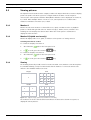
en
Installation and Operation manual
Divar 700 Series
Table of Contents | en
3
Table of Contents
1
Safety
7
1.1
Safety precautions
7
1.2
Important safety instructions
7
1.3
Important Notices
9
1.4
FCC and UL
11
1.5
Bosch notices
12
2
Introduction
13
2.1
Digital video recorder for surveillance applications
13
2.1.1
Versions
13
2.1.2
Software
14
2.1.3
Firmware upgrades
14
2.1.4
Manuals
14
2.1.5
Features
15
2.1.6
On-screen help
15
2.2
Unpacking
15
2.2.1
Package contents
15
2.3
Installation environment
17
2.3.1
Mounting
17
2.3.2
Ventilation
17
2.3.3
Temperature
17
2.3.4
Power Supply
17
2.4
Associated equipment
17
3
Quick install
18
3.1
Connections
18
3.2
First-time use
19
3.3
Quick install menu
20
3.3.1
International
20
3.3.2
Schedule
21
3.3.3
Recording
22
3.3.4
Network
23
4
Hardware setup
24
4.1
Desktop installation
24
4.2
Rack mounting
24
4.3
Hard disk installation
25
4.3.1
Mounting instructions
25
4.4
Camera connections
27
4.5
Audio connections (hybrid version only)
28
4.6
Monitor connections
28
4.6.1
VGA
28
4.6.2
CVBS
29
4.6.3
Y/C
29
4.7
Monitor streaming connection (hybrid version)
29
4.8
RS232 COM port connections
30
Bosch Security Systems
Installation and Operation manual
F.01U.246.471 | v3.6 | 2011.11
4
en | Table of Contents
Divar 700 Series
4.9
Keyboard connections
31
4.10
Ethernet connection(s)
32
4.11
RS485 port
32
4.12
Biphase port
33
4.13
USB connectors
35
4.14
External alarm I/O connection
35
4.15
Malfunction relay
37
4.16
Power supply
38
4.17
Maintenance
38
5
Operating instructions
39
5.1
Front panel controls
39
5.1.1
Keys
39
5.1.2
Indicators
41
5.2
Mouse Controls
41
5.3
Viewing pictures
42
5.3.1
Monitor A
42
5.3.2
Monitor B (hybrid version only)
42
5.3.3
Viewing
42
5.4
Live and playback
44
5.4.1
Live mode
44
5.4.2
Accessing playback functions
44
5.4.3
Playback mode
44
5.5
Overview of the menu system
45
5.5.1
Access using the front panel keys
46
5.5.2
Access using the mouse
46
5.5.3
Access using the Intuikey keyboard
46
5.6
Search
47
5.6.1
Date/time search
47
5.6.2
Search
48
5.7
Export and local playback
52
5.7.1
Export
52
5.7.2
Playback
53
5.8
Configuration
54
5.8.1
Monitor settings
54
5.9
System information
58
5.9.1
Status
58
5.9.2
Logbook
61
5.10
Event handling
62
5.10.1
Alarms
62
5.10.2
Contact inputs
63
5.10.3
Motion events
63
5.10.4
Text events
63
5.10.5
Video loss alarm
63
6
Advanced configuration
64
6.1
International
65
6.1.1
Language
65
6.1.2
Time/date
66
F.01U.246.471 | v3.6 | 2011.11
Installation and Operation manual
Bosch Security Systems
Divar 700 Series
Table of Contents | en
5
6.1.3
Time Server
67
6.2
Video & Audio
68
6.2.1
Analog Channels
68
6.2.2
IP Channels
69
6.2.3
Bitrates tab
72
6.3
Schedule
74
6.3.1
Setting the dynamic characteristics
74
6.3.2
Schedule
74
6.3.3
Exceptions
75
6.4
Recording
76
6.4.1
Normal
76
6.4.2
Contact
77
6.4.3
Text
77
6.4.4
Motion
77
6.4.5
Copy
78
6.5
Contacts
79
6.5.1
Contact inputs
79
6.5.2
Relay outputs
79
6.5.3
Contact input properties
79
6.6
Motion
81
6.6.1
Motion detection on analog cameras
81
6.6.2
Motion detection on IP cameras
83
6.7
Text data
84
6.7.1
Bridge
84
6.7.2
DirectIP
84
6.8
Event
86
6.8.1
General
86
6.8.2
Contact
87
6.8.3
Motion
87
6.8.4
Text
87
6.8.5
Video loss
88
6.8.6
Copy
88
6.9
Network
89
6.9.1
Setup - General
89
6.9.2
Setup - Connection 1
90
6.9.3
Setup - Connection 2
91
6.9.4
IP Range
92
6.9.5
Monitor Streaming
93
6.9.6
SNMP
94
6.10
Storage
96
6.10.1
Disk set
96
6.10.2
Disks
97
6.10.3
Service
98
6.10.4
Replacing a disk
98
6.10.5
Raid 4 protection
6.11
Users
100
6.11.1
General
100
6.11.2
Administrator
100
6.11.3
Users 1 - 7
101
6.12
System
103
Bosch Security Systems
99
Installation and Operation manual
F.01U.246.471 | v3.6 | 2011.11
6
en | Table of Contents
Divar 700 Series
6.12.1
Service
103
6.12.2
KBD
103
6.12.3
Serial ports
104
6.12.4
Licenses
105
6.12.5
Logging
105
7
Menu default values
106
7.1
Quick install menu defaults
106
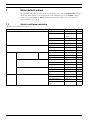
7.2
Monitor view settings defaults
107
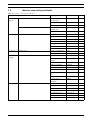
7.3
Configuration menu defaults
108
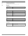
8
Technical specifications
114
8.1
Electrical
114
8.1.1
Mechanical
116
8.1.2
Environmental
116
8.1.3
Electromagnetic and Safety
117
8.1.4
Video bitrates (Kbps) for analog and IP SD cameras
117
8.1.5
Video bitrates (Kbps) for IP HD cameras
117
8.1.6
Accessories (Optional)
118
F.01U.246.471 | v3.6 | 2011.11
Installation and Operation manual
Bosch Security Systems
Divar 700 Series
Safety | en
1
Safety
1.1
Safety precautions
7
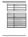
DANGER!
High risk: This symbol indicates an imminently hazardous situation such as "Dangerous
Voltage" inside the product.
If not avoided, this will result in an electrical shock, serious bodily injury, or death.
WARNING!
Medium risk: Indicates a potentially hazardous situation.
If not avoided, this could result in minor or moderate bodily injury.
CAUTION!
Low risk: Indicates a potentially hazardous situation.
if not avoided, this could result in property damage or risk of damage to the unit.
1.2
Important safety instructions
Read, follow, and retain for future reference all of the following safety instructions. Heed all
warnings on the unit and in the operating instructions before operating the unit.
1.
Cleaning - Unplug the unit from the outlet before cleaning. Follow any instructions
provided with the unit. Generally, using a dry cloth for cleaning is sufficient but a moist,
fluff-free cloth or leather shammy may also be used. Do not use liquid cleaners or aerosol
cleaners.
2.
Heat Sources - Do not install the unit near any heat sources such as radiators, heaters,
stoves, or other equipment (including amplifiers) that produce heat.
3.
Ventilation - Any openings in the unit enclosure are provided for ventilation to prevent
overheating and ensure reliable operation. Do not block or cover these openings. Do not
place the unit in an enclosure unless proper ventilation is provided, or the manufacturer's
instructions have been adhered to.
4.
Water - Do not use this unit near water, for example near a bathtub, washbowl, sink,
laundry basket, in a damp or wet basement, near a swimming pool, in an outdoor
installation, or in any area classified as a wet location. To reduce the risk of fire or
electrical shock, do not expose this unit to rain or moisture.
5.
Object and liquid entry - Never push objects of any kind into this unit through openings
as they may touch dangerous voltage points or short-out parts that could result in a fire
or electrical shock. Never spill liquid of any kind on the unit. Do not place objects filled
with liquids, such as vases or cups, on the unit.
6.
Lightning - For added protection during a lightning storm, or when leaving this unit
unattended and unused for long periods, unplug the unit from the wall outlet and
disconnect the cable system. This will prevent damage to the unit from lightning and
power line surges.
7.
Controls adjustment - Adjust only those controls specified in the operating instructions.
Improper adjustment of other controls may cause damage to the unit. Use of controls or
adjustments, or performance of procedures other than those specified, may result in
hazardous radiation exposure.
8.
Overloading - Do not overload outlets and extension cords. This can cause fire or
electrical shock.
Bosch Security Systems
Installation and Operation manual
F.01U.246.471 | v3.6 | 2011.11
8
en | Safety
Divar 700 Series
9.
Power supply cord and plug protection - Protect the power supply cord and plug from
foot traffic, being pinched by items placed upon or against them at electrical outlets, and
its exit from the unit. For units intended to operate with 230 VAC, 50 Hz, the power
supply cord must comply with the latest versions of IEC 60227. For units intended to
operate with 120 VAC, 60 Hz, the power supply cord must comply with the latest
versions of UL 62 and CSA 22.2 No.49.
10. Power disconnect - Units have power supplied to the unit whenever the power cord is
inserted into the power source. The power cord plug is the main power disconnect
device for switching off the voltage for the unit.
11. Power sources - Operate the unit only from the type of power source indicated on the
label. Before proceeding, be sure to disconnect the power from the cable to be installed
into the unit.
12. Servicing - Do not attempt to service this unit yourself. Opening or removing covers may
expose you to dangerous voltage or other hazards. Refer all servicing to qualified service
personnel.
13. Damage requiring service - Unplug the unit from the main AC power source and refer
servicing to qualified service personnel when any damage to the equipment has
occurred, such as:
–
the power supply cord or plug is damaged;
–
exposure to moisture, water, and/or inclement weather (rain, snow, etc.);
–
liquid has been spilled in or on the equipment;
–
an object has fallen into the unit;
–
unit has been dropped or the unit cabinet is damaged;
–
unit exhibits a distinct change in performance;
–
unit does not operate normally when the user correctly follows the operating
instructions.
14. Replacement parts - Be sure the service technician uses replacement parts specified by
the manufacturer, or that have the same characteristics as the original parts.
Unauthorized substitutions could void the warranty and cause fire, electrical shock, or
other hazards.
15. Safety check - Safety checks should be performed upon completion of service or repairs
to the unit to ensure proper operating condition.
16. Installation - Install in accordance with the manufacturer's instructions and in
accordance with applicable local codes.
17. Attachments, changes or modifications - Only use attachments/accessories specified by
the manufacturer. Any change or modification of the equipment, not expressly approved
by Bosch, could void the warranty or, in the case of an authorization agreement, authority
to operate the equipment.
F.01U.246.471 | v3.6 | 2011.11
Installation and Operation manual
Bosch Security Systems
Divar 700 Series
1.3
Safety | en
9
Important Notices
Accessories - Do not place this unit on an unstable stand, tripod, bracket, or mount. The unit
may fall, causing serious injury and/or serious damage to the unit. Use only with the cart,
stand, tripod, bracket, or table specified by the manufacturer. When a cart is used, use
caution and care when moving the cart/apparatus combination to avoid injury from tip-over.
Quick stops, excessive force, or uneven surfaces may cause the cart/unit combination to
overturn. Mount the unit per the manufacturer's instructions.
All-pole power switch - Incorporate an all-pole power switch, with a contact separation of at
least 3 mm in each pole, into the electrical installation of the building.If it is needed to open
the housing for servicing and/or other activities, use this all-pole switch as the main
disconnect device for switching off the voltage to the unit.
Battery replacement - For qualified service personnel only - A lithium battery is located
inside the unit enclosure. To avoid danger of explosion, replace the battery as per
instructions. Replace only with the same or equivalent type recommended by the
manufacturer. Dispose of the replaced battery in an environmentally friendly way and not with
other solid waste. Refer all servicing to qualified service personnel.
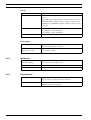
CAUTION!
Class I Laser Product
Invisible laser radiation when open. Avoid exposure to beam.
Coax grounding:
–
Ground the cable system if connecting an outside cable system to the unit.
–
Connect outdoor equipment to the unit's inputs only after this unit has had its grounding
plug connected to a grounded outlet or its ground terminal is properly connected to a
ground source.
–
Disconnect the unit's input connectors from outdoor equipment before disconnecting
–
Follow proper safety precautions such as grounding for any outdoor device connected to
the grounding plug or grounding terminal.
this unit.
U.S.A. models only - Section 810 of the National Electrical Code, ANSI/NFPA No.70, provides
information regarding proper grounding of the mount and supporting structure, grounding of
the coax to a discharge unit, size of grounding conductors, location of discharge unit,
connection to grounding electrodes, and requirements for the grounding electrode.
CAUTION!
This device is intended for the use in public areas only.
U.S. federal law strictly prohibits surreptitious recording of oral communications.
Disposal - Your Bosch product was developed and manufactured with high-quality material
and components that can be recycled and reused. This symbol means that electronic and
electrical appliances, which have reached the end of their working life, must be collected and
disposed of separately from household waste material. Separate collecting systems are
usually in place for disused electronic and electrical products. Please dispose of these units
at an environmentally compatible recycling facility, per European Directive 2002/96/EC.
Environmental statement - Bosch has a strong commitment towards the environment. This
unit has been designed to respect the environment as much as possible.
Electrostatic-sensitive device - Use proper CMOS/MOS-FET handling precautions to avoid
electrostatic discharge.
Bosch Security Systems
Installation and Operation manual
F.01U.246.471 | v3.6 | 2011.11
10
en | Safety
Divar 700 Series
NOTE: Wear required grounded wrist straps and observe proper ESD safety precautions when
handling the electrostatic-sensitive printed circuit boards.
Fuse rating - For protection of the device, the branch circuit protection must be secured with
a maximum fuse rating of 16A. This must be in accordance with NEC800 (CEC Section 60).
Grounding and polarization - This unit may be equipped with a polarized alternating current
line plug (a plug with one blade wider than the other blade). This safety feature allows the
plug to fit into the power outlet in only one way. If unable to insert the plug fully into the
outlet, contact a locally certified electrician to replace the obsolete outlet. Do not defeat the
safety purpose of the polarized plug.
Alternately, this unit may be equipped with a 3-pole grounding plug (a plug with a third pin for
earth grounding). This safety feature allows the plug to fit into a grounded power outlet only.
If unable to insert the plug into the outlet, contact a locally certified electrician to replace the
obsolete outlet. Do not defeat the safety purpose of the grounding plug.
Moving - Disconnect the power before moving the unit. Move the unit with care. Excessive
force or shock may damage the unit and the hard disk drives.
Outdoor signals - The installation for outdoor signals, especially regarding clearance from
power and lightning conductors and transient protection, must be in accordance with NEC725
and NEC800 (CEC Rule 16-224 and CEC Section 60).
Permanently connected equipment - Incorporate a readily accessible disconnect device
external to the equipment.
Pluggable equipment - Install the socket outlet near the equipment so it is easily accessible.
Power resupply - If the unit is forced to power down due to exceeding the specified operating
temperatures, disconnect the power cord, wait for at least 30 seconds, and then reconnect
the power cord.
Rack-mount:
–
Elevated Operating Ambient - If installed in a closed or multi-unit rack assembly, the
operating ambient temperature of the rack environment may be greater than room
ambient. Therefore, consideration should be given to installing the equipment in an
environment compatible with the maximum ambient temperature (Tma) specified by the
manufacturer.
–
Reduced Air Flow - Installation of the equipment in a rack should be such that the amount
of air flow required for safe operation of the equipment is not compromised.
–
Mechanical loading - Mounting of the equipment in the rack should be such that a
hazardous condition is not achieved due to uneven mechanical loading.
–
Circuit Overloading - Consideration should be given to the connection of the equipment
to the supply circuit and the effect that overloading of the circuits might have on
overcurrent protection and supply wiring. Appropriate consideration of equipment
nameplate ratings should be used when addressing this concern.
–
Reliable Earthing - Reliable earthing of rack-mounted equipment should be maintained.
Particular attention should be given to supply connections other than direct connections
to the branch circuit (e.g. use of power strips).
For detailed instructions, please refer to Section 4.2 Rack mounting.
SELV - All the input/output ports are Safety Extra Low Voltage (SELV) circuits. SELV circuits
should only be connected to other SELV circuits.
Video loss - Video loss is inherent to digital video recording; therefore, Bosch Security
Systems cannot be held liable for any damage that results from missing video information. To
minimize the risk of lost digital information, Bosch Security Systems recommends multiple,
redundant recording systems, and a procedure to back up all analog and digital information.
F.01U.246.471 | v3.6 | 2011.11
Installation and Operation manual
Bosch Security Systems
Divar 700 Series
1.4
Safety | en
11
FCC and UL
FCC & ICES Information
(U.S.A. and Canadian Models Only)
This equipment has been tested and found to comply with the limits for a Class B digital
device, pursuant to part 15 of the FCC Rules. These limits are designed to provide reasonable
protection against harmful interference in a residential installation. This equipment
generates, uses, and can radiate radio frequency energy and, if not installed and used in
accordance with the instructions, may cause harmful interference to radio communications.
However, there is no guarantee that interference will not occur in a particular installation. If
this equipment does cause harmful interference to radio or television reception, which can be
determined by turning the equipment off and on, the user is encouraged to try to correct the
interference by one or more of the following measures:
–
reorient or relocate the receiving antenna;
–
increase the separation between the equipment and receiver;
–
connect the equipment into an outlet on a circuit different from that to which the
–
consult the dealer or an experienced radio/TV technician for help.
receiver is connected;
Intentional or unintentional modifications, not expressly approved by the party responsible
for compliance, shall not be made. Any such modifications could void the user's authority to
operate the equipment. If necessary, the user should consult the dealer or an experienced
radio/television technician for corrective action.
The user may find the following booklet, prepared by the Federal Communications
Commission, helpful: How to Identify and Resolve Radio-TV Interference Problems. This booklet
is available from the U.S. Government Printing Office, Washington, DC 20402, Stock No. 004000-00345-4.
INFORMATIONS FCC ET ICES
(modèles utilisés aux États-Unis et au Canada uniquement)
Suite à différents tests, cet appareil s'est révélé conforme aux exigences imposées aux
appareils numériques de classe B, en vertu de la section 15 du règlement de la Commission
fédérale des communications des États-Unis (FCC), et en vertu de la norme ICES-003 d'Industrie
Canada. Ces exigences visent à fournir une protection raisonnable contre les interférences
nuisibles lorsque l'appareil est utilisé dans le cadre d'une installation résidentielle. Cet
appareil génère, utilise et émet de l'énergie de radiofréquences et peut, en cas d'installation
ou d'utilisation non conforme aux instructions, engendrer des interférences nuisibles au
niveau des radiocommunications. Toutefois, rien ne garantit l'absence d'interférences dans
une installation particulière. Il est possible de déterminer la production d'interférences en
mettant l'appareil successivement hors et sous tension, tout en contrôlant la réception radio
ou télévision. L'utilisateur peut parvenir à éliminer les interférences éventuelles en prenant
une ou plusieurs des mesures suivantes:
–
Modifier l'orientation ou l'emplacement de l'antenne réceptrice;
–
Éloigner l'appareil du récepteur;
–
Brancher l'appareil sur une prise située sur un circuit différent de celui du récepteur;
–
Consulter le revendeur ou un technicien qualifié en radio/télévision pour obtenir de
l'aide.
Toute modification apportée au produit, non expressément approuvée par la partie
responsable de l'appareil, est strictement interdite. Une telle modification est susceptible
d'entraîner la révocation du droit d'utilisation de l'appareil.
La brochure suivante, publiée par la Commission fédérale des communications (FCC), peut
s'avérer utile : How to Identify and Resolve Radio-TV Interference Problems (Comment identifier
Bosch Security Systems
Installation and Operation manual
F.01U.246.471 | v3.6 | 2011.11
12
en | Safety
Divar 700 Series
et résoudre les problèmes d’interférences de radio et de télévision). Cette brochure est
disponible auprès du U.S. Government Printing Office, Washington, DC 20402, États-Unis,
sous la référence n° 004-000-00345-4.
Disclaimer
Underwriter Laboratories Inc. ("UL") has not tested the performance or reliability of the
security or signaling aspects of this product. UL has only tested fire, shock and/or casualty
hazards as outlined in UL's Standard(s) for Safety for Information Technology Equipment, UL
60950-1. UL Certification does not cover the performance or reliability of the security or
signaling aspects of this product.
UL MAKES NO REPRESENTATIONS, WARRANTIES, OR CERTIFICATIONS WHATSOEVER
REGARDING THE PERFORMANCE OR RELIABILITY OF ANY SECURITY OR SIGNALINGRELATED FUNCTIONS OF THIS PRODUCT.
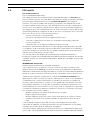
1.5
Bosch notices
Copyright
This manual is the intellectual property of Bosch Security Systems and is protected by
copyright.
All rights reserved.
Trademarks
All hardware and software product names used in this document are likely to be registered
trademarks and must be treated accordingly.
NOTE:
This manual has been compiled with great care and the information it contains has been
thoroughly verified. The text was complete and correct at the time of printing. The ongoing
development of the products may mean that the content of the user guide can change without
notice. Bosch Security Systems accepts no liability for damage resulting directly or indirectly
from faults, incompleteness or discrepancies between the user guide and the product
described.
More information
For more information please contact the Bosch Security Systems location nearest you or visit
www.boschsecurity.com
F.01U.246.471 | v3.6 | 2011.11
Installation and Operation manual
Bosch Security Systems
Divar 700 Series
Introduction | en
2
Introduction
2.1
Digital video recorder for surveillance applications
13
The Divar 700 Series is a video recording system that records multiple camera signals while
simultaneously providing live multiscreen viewing and playback.
The unit has comprehensive search and playback facilities for viewing stored video. Once
configured, all recording takes place in the background without requiring operator
intervention. For analog and SD IP cameras the maximum recording rates of 30 (NTSC) and 25
(PAL) images per second, per channel, are guaranteed. For HD IP cameras recording rates of
up to 60 images per second for 720p and 30 images per second for 1080p, per channel, are
supported. The recording rate and quality are selectable per camera. Up to four internal hard
disks can be used to provide various storage capacities for recording.
All models have extensive alarm handling functions and telemetry control. Alarm functions
include motion detection in user-definable areas of the image on any camera input.
The unit can be easily operated and programmed via the on-screen display menu system using
the front panel control keys or the mouse. Connect a KBD (Intuikey) keyboard for PTZ control
and to improve the ease-of-use. Full-screen, quad and multiscreen viewing is available. VGA,
CVBS and Y/C video outputs in either NTSC or PAL are provided.
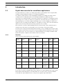
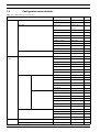
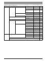
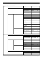
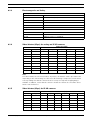
2.1.1
Versions
There are various Divar 700 Series models available:
Model
Analog A/V
Monitor
Dual mono
number
inputs
outputs
outputs
2
2
DHR754
16
IP channels DVD
writer
0 (+16
Network
ports
Yes
2
Yes
1
No
1
Yes
1
No
1
Yes
2
Yes
1
Yes
1
optional)
DHR753
16
2
2
0 (+16
optional)
DHR751
16
2
2
0 (+16
optional)
DHR732
8
2
2
0 (+8
optional)
DHR730
8
2
2
0 (+8
optional)
DNR754
0
1
1
16 (+16
optional)
DNR753
0
1
1
16 (+16
optional)
DNR732
0
1
1
8 (+8
optional)
The optional IP channels are activated with a license.
Each of these models is available with storage capacities of either 500 GB, 2 TB, 4 TB or 8 TB.
Models with 4 TB and 8 TB have four hard disks. These models can be operated in RAID-4
mode with the optional RAID-4 license. This protects against single disk failures.
Bosch Security Systems
Installation and Operation manual
F.01U.246.471 | v3.6 | 2011.11
14
en | Introduction
Divar 700 Series
Hybrid verions (DHR)
The DHR hybrid versions have looping auto-terminating analog video inputs and outputs, and
audio inputs and outputs. Two VGA connectors provide outputs for an A and a B monitor.
Monitor A displays full-screen or multiscreen digital pictures that can be frozen and zoomed.
Monitor B displays live full-screen or multiscreen pictures. Both 8-channel and 16-channel
versions operate in exactly the same way except that fewer camera, audio, and alarm inputs
are present, and the number of available multiscreen views differs.
Network verions (DNR)
The DNR network versions have single VGA, CVBS and Y/C video output connectors for an A
monitor. Monitor A displays full-screen or multiscreen digital pictures that can be frozen and
zoomed.
2.1.2
Software
The BVC application is used via the network for live viewing and playback. The Configuration
Manager application detects IP devices and configures BVIP devices. The Divar 700
Configuration Tool is used to configure the Divar 700 recorders on the network.
Seven simultaneous users can control multiple units. Authenticity checks for both local and
remote playback are available. A dedicated PC player is provided for the authenticated
playback of archived video files. The PC-based Configuration Tool facilitates the installation of
the unit.
An SDK (software development kit) is available to integrate the unit into third party
management software.
2.1.3
Firmware upgrades
Firmware upgrades are released periodically. Check the Bosch Security website for the latest
version.
Note:
Configuration files that are saved before the upgrade can be imported after the upgrade.
2.1.4
Manuals
Two printed manuals are supplied:
–
–
Quick Installation guide - gives a brief overview on how to set up and install the product.
Installation and Operation manual (this manual) - a detailed description of how to install
and operate the product.
Three additional manuals in PDF format are supplied on the CD-ROM:
–
Configuration Tool operation manual - a detailed description for administrators on how to
use the Configuration Tool to set up the Divar 700 Series.
–
Bosch Video Client operation manual - a detailed description for end-users and
administrators on how to set up and operate the Bosch Video Client software.
–
Archive Player operation manual - a detailed description for end-users and administrators
on how to set up and operate the Archive Player software.
F.01U.246.471 | v3.6 | 2011.11
Installation and Operation manual
Bosch Security Systems
Divar 700 Series
2.1.5
Introduction | en
15
Features
The Divar 700 Series has the following features:
–
8 or 16 looped-through, auto-terminating camera inputs (hybrid versions)
–
8 or 16 audio inputs (hybrid versions)
–
Audio support for IP cameras
–
Two dual mono audio outputs (hybrid versions)
–
Dual monitor outputs (hybrid versions)
–
Full-screen and various multiscreen display capabilities in live and playback modes
–
Spot monitor output with sequencing, multiscreen, and OSD (hybrid versions)
–
Optional support for up to 8 (or 16) SD or HD IP cameras on hybrid versions
–
Up to 32 SD or HD IP cameras on network versions
–
Simultaneous recording and playback
–
Internal hard disk video storage (front replaceable by user)
–
10/100/1000Base-T Ethernet port for Ethernet connection and networking
–
External KBD keyboard connection
–
8 or 16 switching (alarm) inputs and 4 alarm outputs
–
Motion detection
–
Video loss detection
–
Audible alarm
–
Pan, tilt, and zoom camera control via RS485 and biphase
–
Two RS232 serial ports for serial communication
–
Local archiving via USB
–
Local archiving via built-in DVD writer (not all versions)
–
Playback of local archive sources
–
iSCSI support for external network storage
–
Text input support
–
Extensive search facilities, including time-based, event/alarm-based, recorded
motion-based and text-based search
–
2.1.6
On-board RAID4 (optional)
On-screen help
On-screen context-sensitive help is available. Just press the help
button to see the help
text associated with your current activity. Press the escape
2.2
button to exit help.
Unpacking
Inspect the package for visible damage. If any items appear to have been damaged during
transport, notify the shipping company. Unpack carefully. This is electronic equipment and
should be handled with care to prevent damage to the unit. Do not attempt to use the unit if
any components are damaged. If any items are missing, notify your customer service
representative or Bosch Security Systems sales representative. The shipping carton is the
safest container in which to transport the unit. Save it and all packing materials for future use.
If the unit must be returned, use the original packing materials.
2.2.1
Package contents
Check for the following items:
Bosch Security Systems
–
Divar 700 Series unit
–
USB mouse
–
Quick installation guide
–
Divar 700 Series Installation and Operation manual (this manual)
Installation and Operation manual
F.01U.246.471 | v3.6 | 2011.11
16
en | Introduction
Divar 700 Series
–
A 25-pin D-type switching and alarm connector board
–
A 15-pin D-type connector board (used for Biphase PTZ connections)
–
A 3-pin screw terminal connector (used for RS485 PTZ connection)
–
Power supply cord
–
Shielded network cross-over cable (for service and testing purposes)
–
Rack mounting kit
–
A CD-ROM containing the software and manuals
F.01U.246.471 | v3.6 | 2011.11
Installation and Operation manual
Bosch Security Systems
Divar 700 Series
Introduction | en
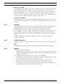
2.3
Installation environment
2.3.1
Mounting
17
The Divar 700 Series is supplied as a desktop unit. If desired, the unit can be rack mounted
using the rack mounting kit supplied with the unit.
2.3.2
Ventilation
Ensure that the location planned for the installation of the unit is well ventilated. Take note of
the locations of the cooling vents in the unit's enclosure and ensure that they are not
obstructed.
2.3.3
Temperature
Observe the unit's ambient temperature specifications when choosing an installation space.
Extremes of heat or cold beyond the specified operating temperature limits may cause the
unit to fail. Do not install the unit on top of hot equipment.
2.3.4
Power Supply
Ensure that the site's AC power supply is stable and within the rated voltage of the unit. If the
site's AC power is likely to have spikes or power dips, use power line conditioning or an
uninterrupted power supply (UPS).
2.4
Associated equipment
A typical system could contain the following components (not included with the unit):
–
A primary monitor for multiscreen monitoring (monitor A)
–
A second monitor for spot/alarm monitoring for hybrid version (monitor B)
–
Cameras with 1 Vpp composite video outputs
–
IP cameras (see datasheet for supported models)
–
Amplified microphone(s)
–
Audio amplifier with speaker(s)
–
Video coaxial cable with BNC connectors for connecting the video signals
Audio cable with RCA connectors for connecting audio signals.
–
AC power supply outlet for the unit that allows for secure isolation (the unit has no on/
off switch for security reasons)
–
A KBD Intuikey keyboard
–
PC for Bosch Video Client and Configuration Tool applications
–
Pan/tilt/zoom control units
–
ATM/POS bridge device for integrating with ATM/POS applications over RS232C or TCP/
IP socket interface
Bosch Security Systems
Installation and Operation manual
F.01U.246.471 | v3.6 | 2011.11
18
3
en | Quick install
Divar 700 Series
Quick install
To get the unit quickly operational, make the connections described below and then enter the
relevant data in the Quick install menu.
The Quick install menu appears the first time the unit is started. When the relevant
information is entered, the unit will be operational.
3.1
Connections
B
Ethernet
KBD in
-|+|G
B
B
1
RS
485
3
5
7
9
11
13
15
6
8
10
12
14
16
L
A
A
Com 1
Com 2
Biphase
Alarm I/O
A
R
MAL
OUT
N0 | C | NC
USB
KBD out
AC
VGA
Monitor out
IR ext
USB
1
2
3
4
1
2
3
4
CVBS
Y/C
5
6
7
8
5
6
7
8
Video in
10
11
12
9
10
11
12
Video in
Video out
B
2
Audio in
4
13
14
15
16
13
14
15
16
Video in
Video out
Secondary Ethernet
Video out
Ethernet
KBD in
-|+|G
A
Audio out
9
RS
485
L
Com 1
Com 2
Biphase
Alarm I/O
R
MAL
OUT
N0 | C | NC
KBD out
USB
USB
IR ext
VGA
Monitor out
CVBS
Y/C
A
Audio out
AC
Secondary Ethernet
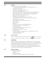
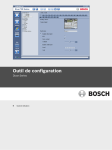
Figure 3.1 Back panel connections for hybrid and network versions
1.
For hybrid versions, connect the cameras to the BNC Video in connectors (automatically
terminated).
2.
Connect monitor A to the CVBS, Y/C, or VGA (supporting 1280x1024) output MON A.
3.
Connect the USB mouse to a USB port.
4.
Connect monitor B to the CVBS, Y/C, or VGA (supporting 1024x768) output MON B*.
5.
Connect up to 16 audio signals to the RCA Audio in connectors*.
6.
Connect the RCA Audio out connector(s) to a monitor or an audio amplifier.
7.
Connect up to 16 inputs to the Alarm I/O via the 25-pin connector board.
8.
Connect up to 4 alarm outputs to the Alarm I/O via the 25-pin connector board.
9.
Connect the malfunction output (MAL OUT) via the screw terminal adapter.
10. Connect an Intuikey keyboard to the KBD in socket and connect the terminator (supplied
with the keyboard) to the KBD out socket.
11. Connect a Bosch pan/tilt/zoom control unit to the Biphase port (via the 15-pole D-type
connector board).
12. Connect a third-party pan/tilt/zoom control unit to the RS485 port (via the screw
terminal adapter).
13. Connect to your network via the Ethernet port. (Some versions have a Secondary
Ethernet port which can be used as a separate network connection.)
14. Connect your IP cameras to the network.
Switch on all connected equipment.
15. Connect the power cord to the unit.
F.01U.246.471 | v3.6 | 2011.11
Installation and Operation manual
Bosch Security Systems
Divar 700 Series
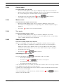
3.2
Quick install | en
19
First-time use
The unit first determines if camera inputs are PAL or NTSC and selects the output mode for
the monitor. If only IP cameras are connected, the system defaults to PAL. The unit starts with
a multiscreen display.
See Section 4.4 Camera connections, page 27 for more details and for instructions on
overriding the operating mode.
The Quick install menu opens the first time the unit is used. Fill in the basic settings in the
tabs to get the unit operational. The unit begins recording automatically when the Quick
install menu is closed.
To open the Quick install menu at any other time:
1.
Press the menu
2.
The main menu appears on monitor A.
button.
3.
Click Configuration and then Quick install.
Navigating
Use the USB mouse or the following front panel keys:
Bosch Security Systems
–
Use the enter
–
Use the arrow
–
Use the escape
button to select a submenu or item.
buttons to move through a menu or list.
button to go back or to switch off the menu.
Installation and Operation manual
F.01U.246.471 | v3.6 | 2011.11
20
en | Quick install
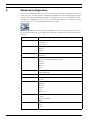
3.3
Divar 700 Series
Quick install menu
The Quick install menu contains four tabs: International, Network, Schedule, and Recording.
Navigate through these tabs using Back and Next. Click Undo to cancel changes made in the
active tab. Click Close to exit the Quick install menu. Changing Quick install settings
overwrites customized settings.
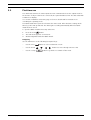
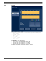
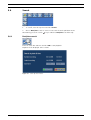
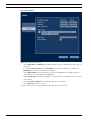
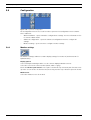
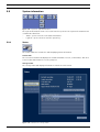
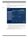
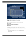
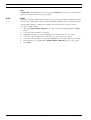
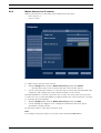
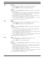
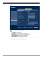
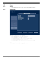
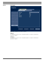
3.3.1
International
Figure 3.2 Quick install menu - International
Language — Select the language for the menu from the list.
Time zone
Time format
— Select a time zone from the list.
— Select either a 12 or a 24 hour clock format.
Time — Fill in the current time.
Date format — Select a date format with month (MM), day (DD), or year (YYYY) first.
Date
F.01U.246.471 | v3.6 | 2011.11
— Fill in the current date.
Installation and Operation manual
Bosch Security Systems
Divar 700 Series
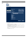
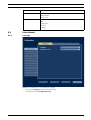
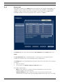
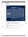
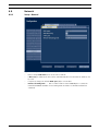
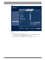
3.3.2
Quick install | en
21
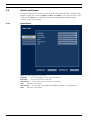
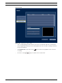
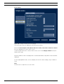
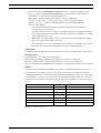
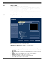
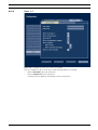
Schedule
Figure 3.3 Quick install menu - Schedule
The currently active weekly schedule is shown. Each color represents an available profile:
–
Yellow - Profile 1
–
Dark blue - Profile 2
–
Green - Profile 3
–
Pink - Profile 4
–
Light blue - Profile 5
–
Brown - Profile 6
Click Overwrite to start making changes.
–
Select on which day the week should start and end.
–
Select when the day begins and ends on weekdays.
–
Select when the day begins and ends on weekends.
The display is automatically updated when settings are changed.
Bosch Security Systems
Installation and Operation manual
F.01U.246.471 | v3.6 | 2011.11
22
en | Quick install
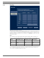
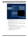
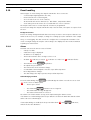
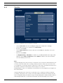
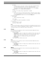
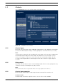
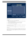
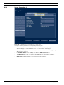
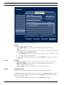
3.3.3
Divar 700 Series
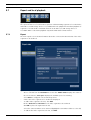
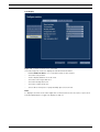
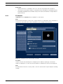
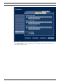
Recording
Figure 3.4 Quick install menu - Recording
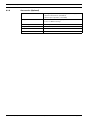
Set the Normal recording Resolution, Quality, and Frame rate for each profile in the table. Set
the Alarm and Motion recording Resolution, Quality, and Frame rate. These settings are set for
all profiles. If advanced settings were previously made, click Overwrite to replace them with
Quick install settings.
Note:
The resolution selection shows only CIF, 2CIF or 4CIF resolutions. When selecting one of
these for a camera that supports different resolutions, the following conversions apply:
Setting
QVGA/VGA cameras
1080p/720p cameras
720p cameras
CIF
QVGA
720p
720p
2CIF
QVGA
720p
720p
4CIF
VGA
720p
720p
The recording panel shows when conversions are applied and when bitrate limitations are
enforced due to bandwidth management settings.
F.01U.246.471 | v3.6 | 2011.11
Installation and Operation manual
Bosch Security Systems
Divar 700 Series
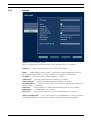
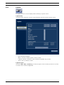
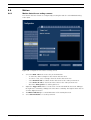
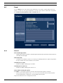
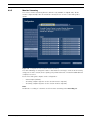
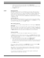
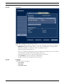
3.3.4
Quick install | en
23
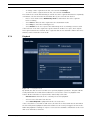
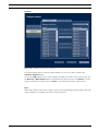
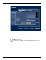
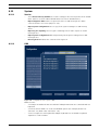
Network
Figure 3.5 Quick install menu - Network
Fill in the settings that control the behavior of the unit with respect to a network.
DVR name — Enter a unique DVR name to be used in the network.
DHCP — Enable DHCP to have IP address, Subnet mask, and Default gateway assigned
automatically by the DHCP server of the network. The actual values are displayed.
IP address — Fill in the IP address when DHCP is not enabled.
Subnet mask
— Fill in the Subnet mask when DHCP is not enabled.
Default gateway
Auto DNS address
— Fill in the Default gateway when DHCP is not enabled.
— Enable to have the DNS server IP address assigned automatically. The
assigned address is displayed.
DNS server — Fill in the DNS server address when Auto DNS address is not enabled.
MAC address — The MAC address is read only.
Connection — Shows current network speed of the primary Ethernet connection.
Remote streaming limit
— Enter a value between 0 and 1000 Mbps to restrict the network
bandwidth available for streaming audio and video to all BVC workstations combined.
Bosch Security Systems
Installation and Operation manual
F.01U.246.471 | v3.6 | 2011.11
24
4
en | Hardware setup
Divar 700 Series
Hardware setup
This chapter contains detailed information about the hardware installation and connection of
external equipment to the unit. The connector types and their pin signals are described. Most
of the connectors are located at the rear panel of the unit. For convenience, a USB port is
located on the front of the unit to connect a mouse or memory device.
All the input/output ports are Safety Extra Low Voltage (SELV) circuits. SELV circuits should
only be connected to other SELV circuits.
4.1
Desktop installation
Place the unit on a stable, flat surface. Install the two silver side covers:
1.
insert a cover on each side.
2.
Slide the cover towards the front of the unit.
Figure 4.1 Side cover installation
4.2
Rack mounting
The unit can be mounted in a 19-inch rack. A rack mounting kit is supplied with the unit that
includes two rack mounting brackets.
Mounting
1.
Remove the four cross head screws (two on each side) located near the front panel on
the right and left side of the unit.
2.
Secure the supplied brackets to each side using the same four cross head screws (two
on each side) that were just removed.
3.
To install several units directly on top of each other, remove the rubber feet from under
the unit by prying them loose with a small screwdriver.
4.
Install the unit into the rack using the hardware supplied with the rack and following the
rack manufacturer’s instructions.
Figure 4.2 Securing the rack mounting bracket
F.01U.246.471 | v3.6 | 2011.11
Installation and Operation manual
Bosch Security Systems
Divar 700 Series
Hardware setup | en
25
CAUTION!
When installing the assembly into the rack, do not restrict air flow around the vents located on
the side panels or exceed the recommended operating temperature.
Secure the connection cables to the rack to relieve excessive weight to the back of the unit.
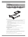
4.3
Hard disk installation
Up to four hard disks can be installed in the DVR. All hard disks are accessed from the front of
the unit by removing the front panel. Do not open the top cover or attempt to service the unit.
No user serviceable parts inside. Refer all servicing to qualified service personnel. Improper
handling or installation could void the warranty of both the hard disk and the DVR.
Note:
Only genuine Bosch hard disks will work in the Divar 700 Series. See the Bosch website or
contact your local Bosch representative for available hard disks.
Installing or removing hard disks does not breach the warranty conditions as long as the
warranty label is not broken.
CAUTION!
Electrostatic discharges
Any electrostatic energy coming in contact with the hard disk or other sensitive internal parts
can damage them permanently. Improper handling could void the warranty of the hard disk.
When working with electrostatic sensitive devices such as a hard disk or the Divar unit, make
sure to use a static-free workstation.
4.3.1
Mounting instructions
DANGER!
Electrical voltage. Risk of electric shock.
Before installation of the hard disk, unplug the power cord of the DVR and wait for at least 30
seconds.
Removing the front panel
Divar
Figure 4.3 Front panel removal
1.
Loosen the two captive cross head screws on the bottom front panel.
2.
Slide the front panel to the right until it is free.
3.
Place the front panel on top of the unit, taking care not to strain the flat cable. If there is
no room on top of the unit, disconnect the flat cable and set the front panel aside.
Bosch Security Systems
Installation and Operation manual
F.01U.246.471 | v3.6 | 2011.11
26
en | Hardware setup
Divar 700 Series
Placing a hard disk
Figure 4.4 Placing a hard disk
1.
Locate the first empty hard disk bay. It is recommended to install the disks in order from
one to four, as labeled. (Note that disks 3 and 4 are mounted in a double bay.)
2.
Unscrew the two torx T10 screws securing the selected bay. Slide the bay from the unit
by pulling it forward.
3.
To replace an installed hard disk, remove the four installation screws, two per side, from
the sides of the bay. Remove the hard disk.
Mount the new hard disk into the bay with four screws, two per side (refer to the hard
disk documentation).
4.
Align and slide the bay back fully into its slot in the unit.
5.
Secure the bay using the two torx T10 screws removed earlier (step 2).
6.
Repeat steps 1-5 for any additional hard disks.
Remounting the front panel
1.
When disk installation is complete, reconnect the flat cable to the front panel, if
necessary.
2.
Align and slide the front panel to the left until it is in place.
3.
Refasten the two captive cross head screws to the front panel.
The location of the hard disks is not important; the unit can determine in which bay they are
installed. When installing hard disks that have recordings from another unit, the recorder
detects this and puts these drives in read-only mode.
Refer to Section 6.10 Storage, page 96 for the correct configuration procedure.
F.01U.246.471 | v3.6 | 2011.11
Installation and Operation manual
Bosch Security Systems
Divar 700 Series
4.4
Hardware setup | en
27
Camera connections
On hybrid units, connect cameras to the Video in connectors on the back of the unit using
75 ohm video coaxial cables with BNC connectors. Optionally, this signal can be looped
through to other equipment via the corresponding Video out connector. The camera input
connectors are auto-terminating. There is no need to add a terminator to the output
connector if no additional equipment is connected.
If the camera signal is looped-through to additional equipment, make sure that the end of the
video connection is terminated with 75 ohm termination.
The unit automatically configures itself as a PAL or NTSC unit. The unit determines the
standard by detecting the signal format of the first connected camera (lowest camera input
number).
On network units, or hybrid units with no analog cameras connected, the detection process
fails and the recorder configures itself as a PAL unit. In this case, no video is visible on an
NTSC monitor.
To change this behaviour select a preferred video mode during start-up.
–
For PAL, press the monitor and camera 1 buttons simultaneously for ten seconds during
–
For NTSC, press the monitor and camera 2 buttons simultaneously for ten seconds
power-up.
during power-up.
The unit retains these manual settings on subsequent start-ups.
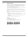
Specifications
Input signal: Composite video 1 Vpp, 75 ohm
Color standard: PAL/NTSC, auto-detect
Gain control: Automatic or manual gain control for each video input
Connector type: BNC looped-through, automatic termination
1
2
3
4
5
6
7
8
5
6
7
8
Video in
1
2
3
4
Video out
Figure 4.5 Eight video inputs with loop-through outputs
Bosch Security Systems
Installation and Operation manual
F.01U.246.471 | v3.6 | 2011.11
28
en | Hardware setup
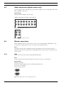
4.5
Divar 700 Series
Audio connections (hybrid version only)
The unit supports up to 16 audio inputs and 4 audio outputs. Connect using audio cable with
RCA compatible connectors.
Specifications
Input signal: Mono RCA, 1 Vpp, 10k ohm
Output signal: Dual mono RCA, 1 Vpp, 10k ohm
1
2
Audio in
3
5
7
9
11
13
15
4
6
8
10
12
14
16
Figure 4.6 Audio input connectors
L
R
A
Audio out
B
Figure 4.7 Audio output connectors
4.6
Monitor connections
On the hybrid version up to two monitors can be connected through the VGA, CVBS, or Y/C
connections. A single monitor can be connected on the network version.
Note:
HD models provide HD recording but not HD local display. Use the Bosch Video Client to
display live HD cameras and SD cameras with Main Profile streams, and recorded video from
these cameras.
4.6.1
VGA
Connect the unit to the monitor using standard VGA cable.
Note:
17-inch or 19-inch LCD monitors with an aspect ratio of 4:3 are recommended.
Specifications
Output signal: VGA
Resolution: 1280 x 1024 (monitor A), 1024 X 768 (monitor B)
Color: True color (32 bit)
Connector type: DE-15
B
A
VGA
Figure 4.8 VGA monitor connectors (hybrid version)
F.01U.246.471 | v3.6 | 2011.11
Installation and Operation manual
Bosch Security Systems
Divar 700 Series
4.6.2
Hardware setup | en
29
CVBS
Connect the unit to CCTV monitors using 75 ohm video coaxial cables with BNC connectors.
The unit provides a 1 Vpp CVBS signal.
If the monitor has a loop-through connection without using the loop-through output, then
select the 75 ohm impedance setting on the monitor. If the monitor's loop-through output is
connected to an additional device, the device's termination is set to 75 ohm and the monitor's
termination is set to high impedance. (This is not necessary on devices with automatic
termination.)
Specifications
Output signal: Composite video 1Vpp, 75 ohm, Sync. 0.3Vpp ±10%
Resolution: 704 x 576 PAL, 704 X 480 NTSC
Connector type: BNC
B
A
CVBS
Figure 4.9 CVBS monitor connectors (hybrid version)
4.6.3
Y/C
Connect the unit to a CCTV monitor with Y/C input, using a standard Y/C connection cable.
B
A
Y/C
Figure 4.10
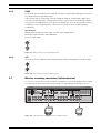
4.7
Y/C monitor connectors (hybrid version)
Monitor streaming connection (hybrid version)
To connect a monitor in a remote streaming configuration, connect the CVBS monitor output
to a video input. Then connect the monitor to the corresponding loop-through connector.
KBD in
-|+|G
Ethernet
B
B
B
A
A
A
1
RS
485
Com 2
Biphase
Alarm I/O
5
7
9
11
13
15
6
8
10
12
14
16
R
MAL
OUT
KBD out
N0 | C | NC
AC
USB
VGA
Monitor out
IR ext
USB
1
2
3
4
1
2
3
4
CVBS
Y/C
5
6
7
8
5
6
7
8
Video in
A
Audio out
9
10
11
12
9
10
11
12
Video in
Video out
Figure 4.11
B
2
Audio in
4
13
14
15
16
13
14
15
16
Video in
Video out
A
Bosch Security Systems
3
L
Com 1
Video out
B
Typical monitor streaming connection (hybrid version)
Installation and Operation manual
F.01U.246.471 | v3.6 | 2011.11
30
4.8
en | Hardware setup
Divar 700 Series
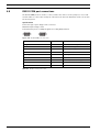
RS232 COM port connections
The RS232 COM ports are used to connect a PC to the unit for service purposes. Use a nullmodem cable to connect the serial port of the PC to the unit. The Baud rate can be selected in
the menu system.
Specifications
Connector type: 9-pole D-type male connector
Maximum input voltage: ±25V
Communicaton protocol: Output signals according EIA/TIA-232-F
COM 1
COM 2
Figure 4.12
RS232 COM port connectors
Signal name
Pin number
Description
DCD_in
1
Carrier detection signal (not used)
RX
2
RS232 receive signal
TX
3
RS232 transmit signal
N/C
4
No connection
System ground
5
System ground
N/C
6
No connection
RTS
7
RS232 request to send signal
CTS
8
RS232 clear to send signal
N/C
9
No connection
Table 4.1
F.01U.246.471 | v3.6 | 2011.11
RS232 console port socket
Installation and Operation manual
Bosch Security Systems
Divar 700 Series
4.9
Hardware setup | en
31
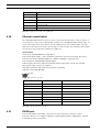
Keyboard connections
The keyboard input and output connectors are used to connect a Bosch Intuikey keyboard to
one or more units. For one unit, connect the keyboard to the KBD in connector. For more
units, connect a cable between the KBD out connector of the first unit and the KBD in
connector of the following unit. Up to 16 Divar 700 units can be connected and controlled in
this manner with one keyboard. Additionally up to 10 Divar 2 recorder units can be operated
with the same keyboard.
The following accessories are available:
–
For short distances (up to 30 m), standard 6-core telecom flat cable can be used to
supply power and signal connections for the keyboard (LTC 8558/00).
–
For distances over 30 m between the keyboard and the DVR, the Keyboard Extension Kit
(LTC 8557) must be used. This kit provides junction boxes, cables, and the appropriate
power supply for the external keyboard. The recommended cable type is Belden 8760 or
equivalent.
–
By using a keyboard Port Expander unit (LTC 2604) up to 4 Intuikey keyboards can
–
With the Video Manager (LTC 2605), up tp 16 Divar recorders and up to 6 monitors can
operate recorder units.
be operated from 1 to 4 separate Intuikey keyboards.
Termination
Connect the keyboard terminator (supplied with the Intuikey keyboard) to the KBD out
connector. If multiple units are controlled with a single keyboard, the KBD out connector of
the last unit must be terminated.
Specifications
Communicaton protocol: RS485
Maximum signal voltage: ± 12V
Power supply: 11 - 12.6 VDC, maximum 400 mA
Maximum cable length: 30 meters (using standard 6-core telecom flat cable), or 1.5
kilometers (using Belden 8760 or equivalent in combination with the LTC 8557).
Cable type: black (cross-over) cable (supplied with keyboard)
Termination: 390 ohm terminator
KBD IN
KBD OUT
Figure 4.13
Keyboard input and output connectors
Pin number
Signal
1
+12 VDC (11 V Min to 12.6 V Max, 400 mA Max)
2
System ground
3
Keyboard plus line
4
Keyboard minus line
5
System ground
6
System ground
Table 4.2 Keyboard In - RJ11 socket (KBD in)
Bosch Security Systems
Installation and Operation manual
F.01U.246.471 | v3.6 | 2011.11
32
en | Hardware setup
Divar 700 Series
Pin number
Signal
1
No connection
2
System ground
3
Keyboard minus line
4
Keyboard plus line
5
System ground
6
No connection
Table 4.3
4.10
Keyboard out - RJ11 socket (KBD out)
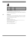
Ethernet connection(s)
The standard RJ-45 Ethernet socket is used to connect the unit directly to a PC, IP camera, or
to a network. To connect to a network hub or switch, use a straight-through network cable. To
connect directly to a PC or IP camera, use the supplied cross-over network cable. Consult
with your local IT personnel for the specific type of cable needed. The maximum cable length
from node to node is limited to 100 meters (300 feet).
Specifications
Connection: 10/100/1000 BaseT, IEEE 802.3
Differential signal voltage: ± 2.8 V maximum, inputs have transient overvoltage protection
Ethernet port details: IEEE 802.3/802.3u - 100Base-TX/10Base-T physical layer
Auto negotiation: 10/100/1000, full/half duplex
Cable length: 100 meters (100 ohm unshielded twisted pair cable or 150 ohm shielded
twisted pair cable, category 5 or higher).
Impedance: built-in compensation for impedance matching
Indicators: ACT, 10/100/1000
ETHERNET
Figure 4.14
Signal name
Pin number
Description
LAN_TX +
1
Ethernet transmit line plus
LAN_TX -
2
Ethernet transmit line minus
LAN_RX +
3
Ethernet receive line plus
N/C
4
No connection
N/C
5
No connection
LAN_RX -
6
Ethernet receive line minus
N/C
7
No connection
N/C
8
No connection
Table 4.4
4.11
Ethernet connector
LAN - RJ-45 Ethernet socket
RS485 port
Connect third-party controllable cameras to the unit for pan, tilt, and zoom control.
(The Pelco D protocol is supported with the following baud settings: 2400 baud; 1 start bit;
8 data bits; 1 stop bit; no parity.)
F.01U.246.471 | v3.6 | 2011.11
Installation and Operation manual
Bosch Security Systems
Divar 700 Series
Hardware setup | en
33
-|+|G
RS
485
MAL
OUT
N0 | C | NC
Figure 4.15
RS485 connector
Signal name
Pin number
Description
TX -
1
Data transmission
TX +
2
Data transmission
GND
3
Shield
Table 4.5 RS485 pin definition
The recommended cable diameter is AWG 28-16 (0.08-1.5 mm2).
To communicate with the controllable camera, select a port number that is the same as the
input number to which the camera is connected (for example, configure a controllable camera
to port 16 if it is connected to channel 16).
4.12
Biphase port
Use the Biphase port for connecting controllable Biphase-compatible cameras. Five Biphase
outputs are provided for dome cameras and pan, tilt, and zoom control. The screw terminal
connection board supplied with the unit simplifies all Biphase connections to the unit and
protects the port against transient over-voltage.
Specifications
Output impedence: 128 ohm
Overvoltage protection: ±40 V maximum
Differential voltage amplitude: 1 V minimum, 2 V maximum with a characteristic load of
220 ohms connected across the differential output
Cable length: 1.5 Kilometers maximum
Recommended cable: Belden 8760
Cable cross section: AWG 26-16 (0.13-1.5 mm2)
Number of loads per output: 4 maximum
Bosch Security Systems
Installation and Operation manual
F.01U.246.471 | v3.6 | 2011.11
34
en | Hardware setup
Divar 700 Series
8
1
15
9
BIPHASE
SHIELD
+
CTRL 1
SHIELD
+
CTRL 2
SHIELD
+
CTRL 3
SHIELD
+
CTRL 4
SHIELD
+
CTRL 5
SHIELD
Figure 4.16
Biphase port connector and connection board
Signal name
Pin number
Description
Code 1 -
1
Biphase control ch. 1 (minus)
Code 1 +
2
Biphase control ch. 1 (plus)
Shield
3
System ground/cable shield
Code 2 -
4
Biphase control ch. 2 (minus)
Code 2 +
5
Biphase control ch. 2 (plus)
Shield
6
System ground/cable shield
Code 3 -
7
Biphase control ch. 3 (minus)
Code 3 +
8
Biphase control ch. 3 (plus)
Shield
9
System ground/cable shield
Code 4 -
10
Biphase control ch. 4 (minus)
Code 4 +
11
Biphase control ch. 4 (plus)
Shield
12
System ground/cable shield
Code 5 -
13
Biphase control ch. 5 (minus)
Code 5 +
14
Biphase control ch. 5 (plus)
Shield
15
System ground/cable shield
Table 4.6
Control port - 15-pole D-type socket
To communicate with the controllable camera, select a port number that is the same as the
input number to which the camera is connected (for example, configure a controllable camera
to port 16 if it is connected to channel 16).
F.01U.246.471 | v3.6 | 2011.11
Installation and Operation manual
Bosch Security Systems
Divar 700 Series
4.13
Hardware setup | en
35
USB connectors
Four USB connectors are located at the rear panel of the unit. For convenience, one USB port
is located on the front of the unit to connect a mouse or memory device.
USB
Figure 4.17
4.14
USB
USB ports
External alarm I/O connection
Alarm inputs and outputs are supplied via a 25-pole D-type socket. The screw terminal input/
output connection board supplied with the unit simplifies all alarm connections to the unit.
Connecting the inputs
Each (alarm) input line can be switched by a contact from devices such as pressure pads,
passive infra-red detectors, smoke detectors, and similar devices. Wire them as either N/O or
N/C. Configure the alarm inputs as N/O or N/C in the menu system. The default is N/O. Inputs
9-16 have no function on an 8-channel analog unit.
Specifications
Alarm input impedence: Internal pull-up 10 K to +5 V
Input voltage range: -5 VDC minimum to 40 VDC maximum
Input voltage treshold: low voltage 0.8 V maximum, high voltage 2.4 V minimum
Cable cross section: AWG 26-16 (0.13-1.5 mm2)
Connecting the alarm outputs
The four alarm output relays respond to input alarms and triggers. Configure the alarm
outputs as N/O or N/C in the menu system. The relays are active for the duration of the driving
event. Only connect resistive loads to the alarm output relays. Do not exceed 30 Vac, 40 Vdc,
500 mA (continuous), or 10 VA on an alarm output relay's contacts.
Output number
Function
1
Alarm
2
Video loss
3
Controllable with control center
4
Controllable with control center
Table 4.7 External alarm I/O
DANGER!
Electrical voltage. Risk of electric shock and damage to the unit.
The contacts must not be used at AC line voltages.
Specifications
Switching current (resistive): 500 mA maximum
Carrying power: 10 VA maximum
Switching voltage (resistive): 30 VAC / 40 VDC maximum
Cable cross section: AWG 26-16 (0.13-1.5 mm2)
Bosch Security Systems
Installation and Operation manual
F.01U.246.471 | v3.6 | 2011.11
36
en | Hardware setup
Divar 700 Series
13
1
25
14
ALARM I/O
1A
1B
2A
2B
1
2
R
E
L
A
Y
GND
3A
3B
4A
4B
IN
9
10
GND
3
4
IN
11
12
GND
5
6
IN
13
14
GND
7
8
Figure 4.18
F.01U.246.471 | v3.6 | 2011.11
IN
15
16
External alarm input and output connector and connection board
Installation and Operation manual
Bosch Security Systems
Divar 700 Series
Hardware setup | en
Signal name
Pin number
Description
Alarm_in_1
1
Alarm input 1
Alarm_in_2
2
Alarm input 2
Alarm_in_3
3
Alarm input 3
Alarm_in_4
4
Alarm input 4
Alarm_in_5
5
Alarm input 5
Alarm_in_6
6
Alarm input 6
Alarm_in_7
7
Alarm input 7
Alarm_in_8
8
Alarm input 8
Alarm_in_9
9
Alarm input 9
Alarm_in_10
10
Alarm input 10
Alarm_in_11
11
Alarm input 11
Alarm_in_12
12
Alarm input 12
Alarm_in_13
13
Alarm input 13
Alarm_in_14
14
Alarm input 14
Alarm_in_15
15
Alarm input 15
Alarm_in_16
16
Alarm input 16
Relay1_A
17
Relay 1 output pole 1
Relay1_B
18
Relay 1 output pole 2
Relay2_A
19
Relay 2 output pole 1
Relay2_B
20
Relay 2 output pole 2
Relay3_A
21
Relay 3 output pole 1
Relay3_B
22
Relay 3 output pole 2
Relay4_A
23
Relay 4 output pole 1
Relay4_B
24
Relay 4 output pole 2
System ground
25
Chassis ground
37
Table 4.8 External I/O - 25-pole D-type socket
4.15
Malfunction relay
The malfunction relay will be activated upon critical system errors such as, high temperatures
inside the unit, excessive voltages, missing disks or disk failures. Connect using the supplied
screw terminal adapter. The recommended cable diameter is AWG 28-16 (0.08-1.5 mm2).
-|+|G
RS
485
MAL
OUT
N0 | C | NC
Figure 4.19
Malfunction relay output
Specifications
Switching current (resistive): 500 mA maximum
Carrying power: 10 VA maximum
Switching voltage (resistive): 30 VAC / 40 VDC maximum
Bosch Security Systems
Installation and Operation manual
F.01U.246.471 | v3.6 | 2011.11
38
en | Hardware setup
4.16
Divar 700 Series
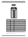
Power supply
Power is supplied to the unit via the IEC-style socket. For security reasons, the unit has no on/
off switch. This means that the unit is always powered as long as the power cable from the
unit is connected to a live power socket.
Specifications:
Input Voltage: 100 - 240 VAC ±10%
Current: 0.7A - 0.3 A
Input Frequency: 50/60 Hz
AC
Figure 4.20
Signal name
Pin
Description
LIVE
Top
AC live
NEUTRAL
Bottom
AC neutral
PE
Middle
Protective Earth
Table 4.9
4.17
Power supply socket
Power supply socket
Maintenance
Maintenance of this unit is limited to external cleaning and inspection. Refer all servicing to
qualified service personnel.
DANGER!
Electrical voltage. Risk of electric shock.
Do not open the top cover or attempt to service the unit. No user serviceable parts inside.
Refer all servicing to qualified service personnel. Opening the top cover will void the warranty!
F.01U.246.471 | v3.6 | 2011.11
Installation and Operation manual
Bosch Security Systems
Divar 700 Series
5
Operating instructions | en
39
Operating instructions
These instructions explain the purpose of the front panel keys. The functions available can be
limited by setting passwords. Some functions may also require a software license.
An administrator has access to many more functions in the menu.
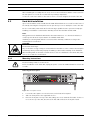
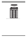
5.1
Front panel controls
Figure 5.1 Front panel controls
5.1.1
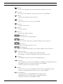
Keys
The keys on the front panel control all functions. Symbols on the keys show the functions.
Inactive keys emit an audible beep when pressed.
Arrow keys:
Up
–
–
Down
Left
Right
move around through menu items or values when in menu mode
in PTZ mode, the arrow keys can be used to control the pan, tilt, or zoom functions
of the selected camera
–
moves the visible area of the selected image in digital zoom mode
Enter key
–
selects a submenu or menu item, or confirms selections made in menus
–
the selected cameo is shown full screen when viewing video in multiscreen mode
ESC key
–
press to return to previous level or to exit menu system without saving
Full screen key
–
press to go to full screen mode
Quad key
–
press to go to quad mode
–
in quad mode, press to toggle between the enabled quad screens
Multiscreen key
–
press to go to multiscreen mode
–
in multiscreen mode, press to toggle between enabled 3x3 and 4x4 screens
Digital zoom key
–
zooms in on the active full screen camera display
Sequence key
–
Bosch Security Systems
view cameras in sequence on full-screen or quad displays
Installation and Operation manual
F.01U.246.471 | v3.6 | 2011.11
40
en | Operating instructions
Divar 700 Series
OSD key
–
press to view date/time and camera information, date/time only, or none
Search key
–
press to open the date/time search menu to look for recorded images
PTZ key
–
enables either pan/tilt or pan/zoom modes
Freeze key
–
in live mode, press to freeze the selected image
Menu key
–
opens the menu system
Help key
–
press to view help
Mute key
–
press to mute audio monitoring
Open/Close key
–
press to open or close the DVD drawer
Export key
–
press to open the export menu; an indicator light is located on the key
–
toggles control between monitor A or B
–
press to acknowledge an alarm event; an indicator light is located on the key
Monitor key
Acknowledge key
Camera keys (1-16)
–
press to see a full-screen display of the analog video input
–
press again to see a full-screen display of an IP camera (if connected)
Pause key
–
in the playback mode, press to freeze the playback picture
Reverse key
–
in live mode, press to start reverse playback of recordings for the displayed cameras
–
in playback mode, press to start or speed up reverse playback
–
in pause mode, press to step back one frame
Play key
–
in live mode, press to resume playback from the last selected playback position
–
in pause or fast forward/reverse modes, press to resume playback
Fast forward key
–
F.01U.246.471 | v3.6 | 2011.11
in live mode, press to start playback from one minute earlier
–
in playback mode, press to speed up the forward playback rate
–
in pause mode, press to step forward one frame
Installation and Operation manual
Bosch Security Systems
Divar 700 Series
Operating instructions | en
41
Stop key
–
while in playback mode, press to return to live mode
Note:
IP camera numbering starts at 9 on an 8-channel hybrid model and at 17 on a 16-channel
hybrid model. So on a 16-channel hybrid unit with IP cameras, camera key 1 selects analog
camera 1 and, when pressed again, IP camera 17.
5.1.2
Indicators
The indicators on the front panel display light or flash to alert of various operating conditions.
Power - lights when the unit is powered
DVD- lights when a DVD is in the unit
USB - lights when a USB memory device is connected to the unit
Network - lights when a remote user is connected to the unit
Record - lights when the unit is recording video
Playback - lights when the unit is in playback mode
Monitor A - indicates monitor A is being controlled
Monitor B - indicates monitor B is being controlled
Temperature - flashes when internal temperature is outside operational range
Alarm - flashes when an alarm is detected
Motion - flashes when motion is detected in a video signal
Video loss - flashes when video loss is detected for a video input
System failure - flashes when a system failure is detected
5.2
Mouse Controls
All functions controlled by the front panel can, alternatively, be accessed using the supplied
USB mouse. All main DVR functions are accessible via the on-screen button panel. To display
the panel (monitor A only), move the mouse pointer to the bottom left of the screen. Press
ESC to remove it from the screen.
Figure 5.2 On-screen button panel
The buttons and indicators of the on-screen button panel work the same as the keys and
indicators on the front panel.
Bosch Security Systems
Installation and Operation manual
F.01U.246.471 | v3.6 | 2011.11
42
en | Operating instructions
5.3
Divar 700 Series
Viewing pictures
The hybrid version has two monitor outputs, A and B. The way in which these monitors display
pictures depends on how the system is configured. When an alarm or motion input is
detected, the camera picture with the Alarm/Motion indicator can be displayed on monitor A,
B, or both. When multiple alarms or motion occur, camera pictures are combined in a
multiscreen window on monitor A, B, or both.
5.3.1
Monitor A
Monitor A is the main monitor. It shows full-screen, quad, or multiscreen live or playback
pictures of both analog and IP cameras. Status messages, alarms, motion, and video loss
warnings are also displayed on this monitor. When the menu system is activated it is
displayed on this monitor.
5.3.2
Monitor B (hybrid version only)
Monitor B displays full-screen, quad, or multiscreen live pictures of analog cameras.
Selecting a monitor to control
To control the display on monitor A:
1.
Check that the
2.
If
light on the front panel is lit.
is not lit, press the monitor
key.
To control the display on monitor B:
5.3.3
1.
Check that the
2.
If
light on the front panel is lit.
is not lit, press the monitor
key
Viewing
The drawing shows all possible views for monitor A and B. Some multiscreen views may have
been disabled during set up. The Divar model and the number of connected cameras also
influence the available multiscreen views.
Single
4x4
1
2
3
4
5
6
7
8
9
10
11
12
13
14
15
16
1
Quad
1
3
3x3
2
4
1
2
3
4
5
6
7
8
9
Figure 5.3 Supports single, quad, 3x3, and 4x4 screen viewing
The multiscreen modes can have different multiscreens that can be shown in sequence to
display all camera pictures.
F.01U.246.471 | v3.6 | 2011.11
Installation and Operation manual
Bosch Security Systems
Divar 700 Series
Operating instructions | en
43
Multiscreen
To view different multiscreen displays on monitor A or B:
1.
2.
Press the multiscreen
key.
–
A multiscreen display of camera pictures appears on the active monitor.
–
The camera keys of the selected cameras light (green).
Press the multiscreen
–
key again to go to the next programmed multiscreen view.
Continue to press the multiscreen
key; the unit cycles through all enabled
multiscreen views.
Full-screen
To view a full-screen shot of a camera:
1.
2.
Press a camera key.
–
A full-screen shot of the selected analog camera appears.
–
The camera key of the selected analog camera lights (green).
–
Press the camera key again to display the linked IP camera.
–
The camera key of the selected IP camera lights (orange).
While in multiscreen mode, press enter
to view the active cameo in full-screen.
Note:
IP camera numbering starts at 9 on an 8-channel hybrid model and at 17 on a 16-channel
hybrid model. So on a 16-channel hybrid unit with IP cameras, camera key 1 selects analog
camera 1 and, when pressed again, IP camera 17.
Sequence
To view a sequence of live camera pictures (full-screen or multiscreen) of several cameras:
1.
Press the sequence
–
2.
Press the sequence
–
key.
A sequence of camera pictures appears, each for a pre-programmed dwell time.
key to stop sequencing.
Zooming, pressing the multiscreen key, or selecting a single camera also stops
sequencing.
Cameo assignment
Assigning cameras to cameos in a multiscreen view:
1.
2.
Use the arrow keys to select a cameo.
Press and hold a camera key to display and assign that camera’s picture in the active
cameo.
3.
Alternatively, right click a cameo with the mouse and choose a video input from the
context menu.
The cameo assignment that was made is used in playback mode as well as in live mode.
Freeze image
Freezing a camera shot on monitor A:
1.
2.
Press the freeze
key to freeze the picture in the active cameo.
Press the freeze
key again to return to live viewing.
Alternatively, right click and select Freeze or Unfreeze from the context menu using the
mouse.
When viewing a camera picture in full-screen mode, then this picture is frozen. The zoom
function can be used on a frozen picture. When changing viewing mode, any frozen pictures
are released.
Bosch Security Systems
Installation and Operation manual
F.01U.246.471 | v3.6 | 2011.11
44
en | Operating instructions
Divar 700 Series
Zoom
To zoom in on a video image:
1.
Press the zoom
–
key.
The picture is enlarged by a factor of 2.
2.
Use the arrow keys to select the area of the picture to be displayed.
3.
Press the zoom
–
key again to zoom in further.
The picture is enlarged by a factor of 4.
4.
Use the arrow keys to select the area of the picture to be displayed.
5.
Press the zoom
key again to return to a full picture and leave the zoom mode.
Alternatively, right click and select Zoom or Exit zoom to enable or disable zoom mode
with the mouse. While in zoom mode, click on an area of the screen to zoom in on. Use
the scroll wheel to zoom in and out.
5.4
Live and playback
5.4.1
Live mode
The live mode is the normal operating mode of the unit where live pictures are viewed from
the cameras. From live mode, switching to playback mode or to the system menu is possible.
5.4.2
Accessing playback functions
Access to playback functions may require a password. Discuss this with the administrator.
1.
To search, use the top menu and click the search icon.
2.
Choose Event search or Date/time search from the pull-down menu.
Alternatively, press the search
key to switch to date/time search directly.
To enter the playback mode, use one of the following keys:
–
Press the rewind
key to start reverse playback of recordings for the displayed
cameras.
–
Press the fast forward
–
Press the play
Press the stop
key to start playback from one minute earlier.
key to resume playback from the last selected playback position.
key to switch back to live viewing. An alarm also switches the unit back to
live viewing.
5.4.3
Playback mode
In playback mode, the video control keys operate as follows:
–
Press the rewind
key to start reverse playback of recordings. Pressing it again and
again increases the display rate to a maximum before returning it back to normal speed
again. Press the rewind
–
Press the pause
–
Press the fast forward
key in the pause mode to step back one frame at a time.
key to freeze the picture.
key to start playback of recordings. Pressing it again and
again increases the display rate to a maximum before returning it back to normal speed
again. Press the forward
–
Press the play
Press the stop
key in the pause mode to step forward one frame at a time.
key to resume playback.
key to switch back to live viewing. An alarm also switches the unit back to
live viewing.
F.01U.246.471 | v3.6 | 2011.11
Installation and Operation manual
Bosch Security Systems
Divar 700 Series
5.5
Operating instructions | en
45
Overview of the menu system
The menu gives access to several functions to help use the unit. Access to some menu items is
password protected. There are three ways of accessing the menu system:
–
via the front panel keys,
–
the USB mouse, or
–
a Intuikey keyboard.
Slight differences in navigation and selection are only due to the differences between the keys
on the unit, the keyboard and the mouse. The menu structure is the same in all cases.
The top menu consists of four main menus with drop-down submenus, a help item and an exit
item.
Figure 5.4 Top menu
Search
The Search menu contains two submenus:
–
Date/time - plays back video from a specific date and time.
–
Events search - searches for events in a specific time frame.
These submenus can only be accessed if playback rights have been given.
Export
The Export menu is used to archive a video clip to a USB memory device or DVD and to play
back archived video locally.
This submenu can only be accessed if export rights have been given.
Configuration
The Configuration menu contains three submenus:
–
Quick installation - opens a wizard to configure basic DVR settings.
–
Advanced configuration - opens the configuration menu to configure all DVR settings.
–
Monitor settings - opens a menu to configure the monitor output settings.
These submenus can only be accessed if configuration rights have been given.
Bosch Security Systems
Installation and Operation manual
F.01U.246.471 | v3.6 | 2011.11
46
en | Operating instructions
Divar 700 Series
System information
The System information menu contains two submenus:
–
Status - opens a menu to view status information.
–
Log Book - opens a menu to view the system log.
Help
The Help function displays a help text.
Exit
Click to log off.
5.5.1
Access using the front panel keys
To open the menu, press the menu
–
key.
The top menu appears on monitor A.
To move through a menu or list, use the arrow
keys on the front
panel.
To select a submenu or item, use the enter
To go back, use the escape
To open the help text, press the help
key
key.
To exit the menu, press the escape
5.5.2
key.
key.
Access using the mouse
To open the menu, move the pointer to the top of the screen.
–
The top menu appears on monitor A.
To select a menu item, move the pointer over it and left click.
5.5.3
Access using the Intuikey keyboard
Press the Menu key to access the top menu. Use the keyboard joystick to navigate through the
menu items.
To select a menu item use the enter
F.01U.246.471 | v3.6 | 2011.11
key on the keyboard.
Installation and Operation manual
Bosch Security Systems
Divar 700 Series
5.6
Operating instructions | en
47
Search
Figure 5.5 Top menu - Search
1.
To search, enter the top menu and click Search.
2.
Choose Date/time search or event or text search from the pull-down menu.
Alternatively, press the search
5.6.1
key to switch to Date/time search directly.
Date/time search
Enter the start date and time and click OK to start playback.
Playback of the displayed cameos starts.
Figure 5.6 Search by date and time
Bosch Security Systems
Installation and Operation manual
F.01U.246.471 | v3.6 | 2011.11
48
en | Operating instructions
5.6.2
Divar 700 Series
Search
Events search criteria
Figure 5.7 Search menu - Events
–
Under Start time and End time, fill in date and time values to determine the time span of
–
To set the Search direction, select Forward to search from start time to end time or
the search.
Backward to search from end time to start time.
–
Under Video inputs, check the inputs to search for (highlight the un-numbered box to
select all). The selected inputs are highlighted.
–
Under Search for check the boxes to search for contact, motion, text, video loss and
system events. Check the Alarms only box so that the search is restricted to alarm
events.
–
F.01U.246.471 | v3.6 | 2011.11
Select Search to start the search.
Installation and Operation manual
Bosch Security Systems
Divar 700 Series
Operating instructions | en
49
Smart motion search criteria
Figure 5.8 Search menu - Smart motion
1.
Set the smart motion search parameters as follows:
–
Under Start time and End time, fill in date and time values to determine the time span of
–
To set the Search direction, select Forward to search from start time to end time or
the search.
Backward to search from end time to start time.
–
Adjust the Trigger level slider to set the level of motion that will be detected. Sliding to
the right raises sensitivity, sliding to the left lowers sensitivity. The highest value detects
even the slightest motion.
–
2.
3.
4.
Bosch Security Systems
Select the input to search using Video input.
To define the motion sensitive area in the smart motion preview cameo window:
–
Select Draw cells and draw in the motion cameo to add or increase detection areas.
–
Select Erase cells and draw in the motion cameo to erase or reduce detection areas.
To activate or clear the entire area, select one of the following:
–
Draw all cells to activate the entire motion detection area.
–
Erase all cells to clear the entire motion detection area.
–
Check the Show grid box to outline grid zones.
Select Search to start the search.
Installation and Operation manual
F.01U.246.471 | v3.6 | 2011.11
50
en | Operating instructions
Divar 700 Series
Text search criteria
Figure 5.9 Search menu - Text data
–
Under Start time and End time, fill in date and time values to determine the time span of
the search.
–
To set the Search direction, select Forward to search from start time to end time or
Backward to search from end time to start time.
–
Under Video inputs, check the inputs to search for (highlight the un-numbered box to
–
Under Search text, enter the text string to search for in the recorded text of the selected
–
Check the Case sensitive box to make the search case sensitive.
–
Select Search to start the search.
select all). The selected inputs are highlighted.
video inputs.
Search results for text searches work the same way as for event search.
F.01U.246.471 | v3.6 | 2011.11
Installation and Operation manual
Bosch Security Systems
Divar 700 Series
Operating instructions | en
51
Search results
Figure 5.10
Search menu - Search results
–
The recording fitting the filter and closest to the selected date and time is shown first.
–
Use the up/down arrow keys to move through the list. The selected recording is shown in
the preview window.
–
Click Full Screen or press the enter
key for a full-screen playback of the selected
recording.
–
Bosch Security Systems
Press the escape
key to return to the search menu.
Installation and Operation manual
F.01U.246.471 | v3.6 | 2011.11
52
en | Operating instructions
5.7
Divar 700 Series
Export and local playback
Figure 5.11
Top menu - Export video
The export menu is accessed from the top menu. It allows writing segments of recorded video
and audio to a USB storage device or recordable DVD. The playback menu allows playback of
segments of recorded video and audio from the local disk set, a USB storage device or
recordable DVD. Local archive playback only works with native format archives.
5.7.1
Export
The main export screen shows information about the connected media and a list of the video
segments to be archived.
Figure 5.12
–
Export video menu
Choose a media from the Destination selection box. Media status displays the status of
the selected device; Free space displays the available space for archiving.
Select Erase to empty the selected memory device.
–
A list of the video segments to be archived is displayed.
–
To add a video segment to the list, click Add.
Fill in a Start time and End time for the video segments to be archived.
Click OK to place the segment in the list.
Select the camera numbers to be archived (highlight the un-numbered box to select all).
–
F.01U.246.471 | v3.6 | 2011.11
To add another video segment to the list, click Add.
Installation and Operation manual
Bosch Security Systems
Divar 700 Series
Operating instructions | en
–
To change a video segment in the list, select it and click Change.
–
To remove a video segment from the list, select it and click Remove.
53
The archive list is saved until archiving is carried out. Video segments that have been partially
overwritten or deleted from the internal hard drive(s) are removed from the list.
–
Place a check mark next to Authenticity check to authenticate the video segments
–
Select Start to write the video segments to the destination media.
–
Select Stop to cancel the archiving process.
–
Select Details for an error report if the authenticity check or archiving is unsuccessful.
before archiving.
If the total size of the video segments is greater than the media’s free space, then only the
first segments that fit are archived. Those segments that are not archived remain in the list so
that they can be archived to new media.
5.7.2
Playback
Figure 5.13
Local playback menu
By default, the unit uses the local disk set to perform playback operations. This panel allows
locally attached devices with archived data to be selected as a source for playback. This
feature allows verification of exported video data locally on the unit.
–
Current source shows the device currently selected for playback.
–
Select a source file name from the list.
–
Select Start Playback to playback from the selected source.
If the selected file is on a DVD or USB source, then the file is first loaded into the unit. When
the file is fully loaded, playback starts and continues to run even if you toggle to the live mode.
While this playback is running no export or event search is available. Switch back to the local
disk set to allow these functions.
Bosch Security Systems
Installation and Operation manual
F.01U.246.471 | v3.6 | 2011.11
54
en | Operating instructions
5.8
Divar 700 Series
Configuration
Figure 5.14
Top menu - Configuration
The Configuration menu is accessed from the top menu. The Configuration menu contains
three submenus:
–
Quick Installation - opens a wizard to configure basic settings. For more information refer
to Section 3 Quick install.
–
Advanced configuration - opens the advanced configuration menu to configure all
–
Monitor Settings - opens a menu to configure monitor settings.
settings.
5.8.1
Monitor settings
The Monitor settings submenu contains display settings for monitor A (and monitor B for
hybrid models).
Display options
Select a transparent background to see the camera display behind the menus.
Select the color for the cameo borders (black, white or gray).
Check the Click to open menus box to require a click in the top or bottom part of monitor A to
open the screen menus. If left unchecked, hoovering near the top or bottom opens the menus.
Multiscreens
Select the multiscreens to be viewed.
F.01U.246.471 | v3.6 | 2011.11
Installation and Operation manual
Bosch Security Systems
Divar 700 Series
Operating instructions | en
55
Sequence
Figure 5.15
Configure monitors menu - Sequence
Select the length of time a camera remains visible on screen (1 to 60 seconds) in the
Sequence dwell time field.
Use the the Add button to move camera inputs or multiscreen views to the sequence list. Use
the Move up or Move down buttons to put them in the desired order. Use Remove to clear a
single item from the sequence list. Use Erase to clear all items from the sequence list.
Note:
When a HD camera is part of the sequence list, it is not shown during sequencing because HD
camera display is not supported on the local user interface.
Bosch Security Systems
Installation and Operation manual
F.01U.246.471 | v3.6 | 2011.11
56
en | Operating instructions
Divar 700 Series
Event display
Figure 5.16
Configure monitors menu - Event display
Select the way events are displayed on both monitor A and B.
Check the Contact inputs events, Motion detection events, Text events or Video loss alarms
boxes to display these events on the screen.
Set the length of time these events remain on the screen in the Display duration field (nonalarm events only).
Enter the number of lines to display in the event list and whether only alarm events should be
displayed.
For live and playback modes, select to display icons in the cameos always, only on alarms or
never.
Note:
A text license is required to see text events.
F.01U.246.471 | v3.6 | 2011.11
Installation and Operation manual
Bosch Security Systems
Divar 700 Series
Operating instructions | en
57
Text display
Figure 5.17
Configure monitors menu - Text display
Select the way text events are displayed on both monitor A and B.
–
Enable Show text data to see a text data overlay on the monitor.
–
Select the text position.
–
Set the display duration of a text event.
–
Select the text foreground color.
–
Select the background color.
–
Select the required font size.
–
Select either monospace or proportionally spaced screen font.
Note:
To display text in live mode either right-click a camera and select Text on/off, or press and
hold the OSD button to toggle text display on and off.
Bosch Security Systems
Installation and Operation manual
F.01U.246.471 | v3.6 | 2011.11
58
en | Operating instructions
5.9
Divar 700 Series
System information
Figure 5.18
Top menu - System information
The System information menu is accessed from the top menu. The System information menu
contains two submenus:
5.9.1
–
Status - opens a menu to view status information.
–
Logbook - opens a menu to view the system log.
Status
The Status submenu contains five tabs displaying status information.
Version Info
The version information tab displays the installed firmware version, serial number, and other
version-related information for service purposes.
Storage status
The storage status tab displays information on disk size and content.
Figure 5.19
F.01U.246.471 | v3.6 | 2011.11
Status menu - Storage status
Installation and Operation manual
Bosch Security Systems
Divar 700 Series
Operating instructions | en
–
Earliest recording - displays date and time of the earliest (oldest) recording on disk.
–
Latest recording - displays date and time of the latest (newest) recording on disk.
–
Total Disk Size - displays the total installed disk space.
–
RAID status - displays enabled if the disks are used as a RAID array.
–
Time till overwrite appr. - estimated time video is retained until overwriting.
–
Authenticity check... - click to check authenticity of recorded audio and video.
–
Disks in active disk set:
–
59
The list shows which internal disks or LUNs on iSCSI arrays are available for
recording in the active disk set.
–
The disk or LUN on which recording is currently performed or scheduled is shown
with a red dot. Other disks or LUNs in the disk set which are available for recording
are marked with a green dot.
When RAID is activated all 4 local drives show a red dot. iSCSI LUNs are not available for recording when RAID is activated.
–
The active disk set is selected during boot if the unit detects multiple disk sets. The
active disk set can also be changed in the Storage configuration pages.
Video signals
The video signals tab displays the system video mode (PAL or NTSC) and video input status.
Recording status
Currently active profile - displays current profile
Alarm recording at input - displays which inputs are in alarm recording mode
Motion recording at input - displays which inputs are in motion recording mode
Current recording status - displays video and audio recording mode and status for each input
Sensors
Displays actual temperature and voltage sensor values. If temperature levels are outside of
the normal range, the displayed values are yellow. If this occurs, check that the ambient
temperature is within the recommended specifications and that there is proper air ventilation.
If the temperature reaches a critical level, the unit automatically shuts down. To restart the
unit, disconnect the power cord, wait for at least 30 seconds, and then reconnect the power
cord.
Sensor name
Lower limit
Upper limit
Processor
5 °C / 41 °F
100 °C / 212 °F
Air inlet
5 °C / 41 °F
45 °C / 113 °F
Air outlet
5 °C / 41 °F
55 °C / 131 °F
Hard disk #1
5 °C / 41 °F
55 °C / 131 °F
Hard disk #2
5 °C / 41 °F
55 °C / 131 °F
Hard disk #3
5 °C / 41 °F
55 °C / 131 °F
Hard disk #4
5 °C / 41 °F
55 °C / 131 °F
Table 5.1 Temperature sensors
Bosch Security Systems
Installation and Operation manual
F.01U.246.471 | v3.6 | 2011.11
60
en | Operating instructions
Divar 700 Series
Voltage level
Lower limit
Upper limit
12 Volt
10.8 V
13.2 V
5 Volt
4.7 V
5.3 V
3.3 Volt
3.1 V
3.5 V
Table 5.2
F.01U.246.471 | v3.6 | 2011.11
Power supply levels
Installation and Operation manual
Bosch Security Systems
Divar 700 Series
5.9.2
Operating instructions | en
61
Logbook
The logbook menu is used to display a filtered history of system events.
Logbook filter
Set various filter criteria to search in a specified time period for various system events.
Figure 5.20
Logbook menu - Logbook filter
–
Enter start and end times.
–
Make a selection of which system events to show.
–
Logbook contents - shows the earliest and latest available log contents.
–
Show - click to show the results.
Logbook results
Shows the Date, Time, and Event type of various system events. A video preview screen of the
selected event is shown, if applicable.
Bosch Security Systems
Installation and Operation manual
F.01U.246.471 | v3.6 | 2011.11
62
en | Operating instructions
5.10
Divar 700 Series
Event handling
Various types of events change the way the unit works. These events are:
–
a contact input signal applied to the unit;
–
motion detection in a camera signal;
–
a loss of video from one of the cameras;
–
an internal alert from the unit itself (i.e. disk failure, temperature alarm).
–
a text string sent to the unit to be recorded with one or more cameras.
The way the unit reacts to events depends on how it is programmed.
An event can change the way the unit works and, if it is an alarm, can require a response from
the user.
Background events
Events can change background tasks that a user may not notice. Unit responses that are not
visible to the user are, for example, a change in recording speed, the activation of the output
relay, or event logging. The unit can also be configured to record upon the activation of an
event or it might change the way the camera images are displayed on the monitors without
requiring user intervention.
5.10.1
Alarms
An alarm can cause the unit to react as follows:
–
A beeper sounds.
–
A status message is displayed.
–
An alarm icon is displayed.
–
The border around a cameo changes color to red.
–
An alarm
indicator, a motion
indicator or a video loss
–
The indicator on the
–
An output relay is activated.
–
The view modes on the monitors change.
indicator flashes.
key flashes.
–
A controllable camera might be moved to a pre-defined position.
–
Recording behavior changes.
–
The unit changes the way it operates via pre-defined profiles.
Acknowledging an alarm
Press the acknowledge key
to acknowledge the alarm or use the mouse to click
on the on-screen button panel.
–
The beeper is silent.
–
The alarm and
indicators are no longer lit.
–
The alarm status message disappears.
–
The last-used view mode is restored.
The alarm icon remains visible as long as the input causing the alarm is active.
If an alarm is not acknowledged, the beeper switches off after the dwell time but the alarm
still needs to be acknowledged.
If auto-acknowledge is enabled, the beeper and the alarm
and
indicators,
switch off after the dwell time.
F.01U.246.471 | v3.6 | 2011.11
Installation and Operation manual
Bosch Security Systems
Divar 700 Series
5.10.2
Operating instructions | en
63
Contact inputs
If a contact input causes an alarm
–
Monitors A and B (hybrid version only) can display an array of pre-selected cameras.
–
Monitor A: The border around the displayed cameos is red. The alarm icon is displayed in
the corresponding cameo. An alarm status message is displayed.
5.10.3
–
The alarm beeper sounds. The alarm
and the
indicators flash.
–
Controllable cameras might be moved to pre-defined positions.
Motion events
If a motion detection signal causes an event
–
Monitors A and B (hybrid version only) can switch to display the motion events.
–
The motion icon is displayed in the corresponding cameo. An alarm status message is
displayed.
–
5.10.4
The motion
indicator on the front panel flashes.
Text events
If a text event signal causes an event
–
Monitors A and B (hybrid version only) can switch to display the text events.
–
The text event icon (yellow) or text alarm icon (red) is displayed in the corresponding
cameo. An alarm status message is displayed.
5.10.5
Video loss alarm
If the loss of a video signal causes an alarm:
Monitor A or B (hybrid version only) can be configured to show the video loss signal.
–
One or both monitors can switch to a multiscreen view. The lost camera signal is
displayed as a black cameo with the video loss message. On monitor A, the border
around the camera with the video loss is red. An alarm status message is displayed.
–
The alarm beeper sounds.
–
The video loss
and
indicators flash.
Acknowledging a video loss alarm
Press the acknowledge key
to acknowlede a video loss alarm.
–
The beeper is silent.
–
The video loss
and
indicators are no longer lit.
–
The alarm status message disappears.
–
The last-used view mode is restored.
If the camera with video loss is visible, the black cameo and the video loss message continue
to be displayed as long as there is no video present.
If an alarm is not acknowledged, the beeper switches off after the dwell time but the alarm
still needs to be acknowledged.
If auto-acknowledge is enabled the beeper, and the video loss
and
indicators,
switch off after the dwell time.
Bosch Security Systems
Installation and Operation manual
F.01U.246.471 | v3.6 | 2011.11
64
6
en | Advanced configuration
Divar 700 Series
Advanced configuration
Access all the parameters that are used to configure the unit via the configuration menu item
of the top menu. The large number of parameters available gives the opportunity to program
extensive functionality. Administrator rights are required to access the configuration menus.
The advanced configuration menu is accessed from the top menu via the configuration menu
item and gives access to all configurable items for the unit.
This menu has 12 major menu groups listed down the left side. The groups have tabs across
the top which provide access to a page where the values and functions can be selected and
changed.
Left tabs
Top tabs
International
Language
Time/date
Time server
Video & Audio
Channels 1-32 (depending on model)
General
Control
Schedule
Schedule
Exceptions
Recording
Profiles 1 to 6
Channels 1-32 (depending on model)
- Normal
- Contact
- Motion
- Text
Contacts
Contact inputs NC
Relay outputs NC
Motion
Channels 1-8 (or 1-16 depending on model)
Text data
Bridge
Direct IP
Event
Profiles 1 to 6
- General
- Contact
- Motion
- Text
- Video loss
Network
Setup
IP range
Monitor streaming
SNMP
Storage
Disk set
Disks
Service
F.01U.246.471 | v3.6 | 2011.11
Installation and Operation manual
Bosch Security Systems
Divar 700 Series
Advanced configuration | en
Left tabs
Top tabs
Users
General
65
Administrator
Users 1 to 7
System
Service
KBD
Serial ports
Licenses
Logging
6.1
International
6.1.1
Language
Figure 6.1 Configuration menu - International - Language
Bosch Security Systems
–
Select your Language from the drop-down list.
–
Select the preferred Temperature unit.
Installation and Operation manual
F.01U.246.471 | v3.6 | 2011.11
66
en | Advanced configuration
6.1.2
Divar 700 Series
Time/date
Figure 6.2 Configuration menu - International - Time/date
–
Select a Time zone from the list (daylight saving time is adjusted accordingly).
–
Select either a 12-hour or a 24-hour clock Time format.
–
Fill in the actual Time.
–
Select a Date format which shows either the month (MM), the day (DD), or the year
(YYYY) first.
–
Enter the actual Date.
–
Set Daylight Saving to Automatic to enable it. Set to Manual and fill in the day, month,
and time of both Start and End time, and the Offset if it differs from the information
associated with your time zone.
Note:
If synchronizing the time causes the the recorder time to be set back less than 10 minutes, the
recorder clock slows down. The recording continues, but more frames are stored for each
second that the recorder time advances. When the recorder time slow-down has made up for
the number of minutes it was ahead, normal clock pace is resumed.
During playback of video recorded with a slowed-down clock, the playback speed appears to
have slowed down.
If synchronizing the time causes the recorder time to be set back more than ten minutes,
recording is suspended. The recorder clock stops until the actual time has advanced to the
last recording timestamp. An alarm message is shown during this condition until the alarm is
acknowledged. When the recorder time has advanced to the timestamp of the newest
F.01U.246.471 | v3.6 | 2011.11
Installation and Operation manual
Bosch Security Systems
Divar 700 Series
Advanced configuration | en
67
recordings, the clock resumes advancing at the normal pace and normal recording behaviour
is resumed.
If you want the recorder to set back the clock more than 10 minutes, but also want the unit to
resume recording immediately, you should either delete all recordings manualy, or set the
recorder time ahead of the latest recording time.
6.1.3
Time Server
Figure 6.3 Configuration menu - International - Time Server
–
The Use time server function synchronizes the time of the unit with the time of a network
time server or another Divar unit. Fill in the IP address of the network time server. If a
time server is not present on the same subnet, the unit searches for a suitable time
server outside its own network. Make sure the Divar gateway is set correctly to find the
time server. Ensure that firewalls do not block NTP traffic via port 123.
–
Click Synchronize to start time synchronization.
Automatic time synchronization (done once every four hours) can only change the clock by a
maximum of 10 minutes (see Note under Section 6.1.2 Time/date).
Bosch Security Systems
Installation and Operation manual
F.01U.246.471 | v3.6 | 2011.11
68
en | Advanced configuration
6.2
Divar 700 Series
Video & Audio
Use this menu to configure the video and audio inputs.
On DHR 730 models tabs 1-8 are for the analog cameras. Higher tabs are for IP cameras.
On DHR 750 models tabs 1-16 are for the analog cameras. Higher tabs are for IP cameras.
On DNR 730 models tabs 1-16 are for IP cameras.
On DNR 750 models tabs 1-32 are for IP cameras.
On models with expanded memory, (revision B models) the bitrates tab follows the camera
number tabs.
6.2.1
Analog Channels
The tabs 1-8 or 1-16 across the top of the menu contain the settings for each of the analog
inputs on a digital hybrid recorder.
Figure 6.4 Configuration menu - Video & Audio - Analog camera
A General tab and a Control tab are available for each analog camera.
General tab
–
Enter a name for the selected input. The name can be up to 16 characters long.
–
The Enable video input setting enables (default) or disables the video and corresponding
audio inputs.
–
Auto contrast - enabled to let the system automatically adjust the contrast for the video
input.
–
Contrast - can be set manually with the slider if Auto contrast is disabled.
–
Enable Audio input when an audio source is connected.
–
The Level meter indicates the strength of the audio input signal.
–
Use the Gain slider to adjust the input sensitivity.
F.01U.246.471 | v3.6 | 2011.11
Installation and Operation manual
Bosch Security Systems
Divar 700 Series
Advanced configuration | en
69
Control tab
–
Enable PTZ when a controllable camera is connected. By default, PTZ is disabled.
–
Select protocol and device address on PTZ bus. (PTZ commands are transmitted across
the RS485 and Biphase bus simultaneously. Each camera should have a unique address
greater than 0.)
6.2.2
IP Channels
A General tab and a Control tab are available for each camera.
Note:
An IP stream must only be connected to a single channel on a single Divar. There should be no
connection to any other device that could influence the settings of the IP device.
Figure 6.5 Configuration menu - Video & Audio - IP camera
IP camera
If an IP connection has already been configured, the IP address, input type, and stream
number is displayed. If a connection has already been established, a video preview appears.
Note:
The Divar will overrule the encoder profile set in the camera itself if required by the following
settings.
Bosch Security Systems
Installation and Operation manual
F.01U.246.471 | v3.6 | 2011.11
70
en | Advanced configuration
Divar 700 Series
Manual setup
Figure 6.6 Configuration menu - Video & Audio - IP camera manual setup
1.
Click Manual setup ... to configure or change an IP camera connection.
–
–
IP address - enter the IP address of the IP camera.
Input - Choose Camera for a camera or a single-channel encoder. Choose Video line
1-4 for a multi-channel encoder.
2.
–
Stream - enter the stream number.
–
Encoder profile - Displays the encoder profile of the IP device.
–
Username/Password - enter the username and password if applicable.
Press OK to confirm settings.
It can take a few seconds to establish a successful connection, after which a video preview
appears.
F.01U.246.471 | v3.6 | 2011.11
Installation and Operation manual
Bosch Security Systems
Divar 700 Series
Advanced configuration | en
71
Auto detect
Figure 6.7 Configuration menu - Video & Audio - IP camera - Auto detect
Click Auto detect ... to assign a detected IP camera to the selected channel. Select
Configure ... to change the IP parameters of the selected camera.
Input name
Enter a name for the selected input. The name can be up to 16 characters long.
Enable video input
This setting enables (default) or disables the video input.
Camera resolutions
Select a set of resolutions that match the available resolutions of the attached IP camera.
Enable SD display on local monitor
Check to limit the video streams from the camera to only those that the unit can locally
decode and display. If unchecked, video from this IP camera is recorded but is not displayed
locally.
Control tab
–
–
Enable PTZ when a controllable camera is connected. By default, PTZ is disabled.
Select a protocol and the communication parameters required for PTZ control of cameras
attached to encoders.
Bosch Security Systems
Installation and Operation manual
F.01U.246.471 | v3.6 | 2011.11
72
en | Advanced configuration
6.2.3
Divar 700 Series
Bitrates tab
Units with IP channels have a Bitrates tab for allocating the total available IP bandwidth to the
individual cameras. DHR models with 8 or 16 IP channels have 36 Mbit/s total bandwidth
available for video streams from IP cameras. DNR recorder models have 72 Mbit/s total
bandwidth available. HD cameras generally require a bit rate of 2MBits/s.
Figure 6.8 Configuration menu - Video & Audio - Bitrates tab
The Bitrates tab lists all IP channels with their Unconstrained bitrate, Ceiling bitrate, and
Status.
The Unconstrained bitrate is maximum bitrate of camera, based on the highest camera
settings for resolution, frame rate and quality in all recording profiles.
The Ceiling bitrate is the maximum bitrate allowed for this camera. This value can be changed
as follows:
1.
Click on a channel.
2.
Select a value in the Bitrate ceiling on channel xx list box.
The Status column shows:
–
OK when the settings for resolution, framerate and quality are honored, and no
limitations apply for any of the profiles.
–
Capped to Ceiling when the ceiling value for the camera is lower than the value
calculated from resolution, framerate and quality settings in the profiles in the recording
F.01U.246.471 | v3.6 | 2011.11
Installation and Operation manual
Bosch Security Systems
Divar 700 Series
Advanced configuration | en
73
panel. This causes the bitrate for the camera to be lower than the value set in the
recording profiles.
–
No Bitstream when the camera can not stream video data due to bitrate limitations.
If the total required bandwidth is greater than the total availble bandwidth, the unit puts
cameras into the No Bitstream state, starting with the highest numbered IP camera.
The total required bandwidth of all cameras based on the ceiling values and the total
bandwidth available in the unit is shown.
Note:
Refer to the data sheet for a list of supported IP cameras and encoders.
Bosch Security Systems
Installation and Operation manual
F.01U.246.471 | v3.6 | 2011.11
74
en | Advanced configuration
Divar 700 Series
6.3
Schedule
6.3.1
Setting the dynamic characteristics
The settings in the Schedule menu provide the opportunity to tap the powerful functionality
of the unit. By planning and setting up the profiles available, efficient use of resources is
achieved that covers most types of working situations. The profiles are scheduled in a weekly
calendar, changing the recording and event behavior at a particular day or time (for example,
weekends or nights). The six profiles that are defined in the Recording menu appear here.
Figure 6.9 Configuration menu - Schedule
The profiles are represented by different colors in a graphical representation of the weekly
schedule. The schedule can be changed by selecting a profile number and then drawing an
active area in the graphical schedule.
6.3.2
Schedule
Configuration
–
The use of profiles is defined in a calendar that covers one week. This calendar is then
repeated for subsequent weeks.
–
A profile is specified at intervals of 15 minutes for each day of the week.
–
Program exception days to change profiles for special days and holidays.
1.
Select a profile number. The selected profile is highlighted.
2.
Click Edit selected profile name to edit the name of the selected profile.
3.
Move down to the schedule. Use the arrow and enter keys or mouse to draw an active
area.
4.
F.01U.246.471 | v3.6 | 2011.11
When finished, select Save to activate the updated schedule.
Installation and Operation manual
Bosch Security Systems
Divar 700 Series
6.3.3
Advanced configuration | en
Exceptions
–
Bosch Security Systems
75
Up to 32 exceptions can be set that override the schedule.
–
To add an exception, select Add. Enter the Date, Time, Duration, and the Profile.
–
To edit an exception, select it and click Change... .
–
To remove an exception, select it and click Remove.
Installation and Operation manual
F.01U.246.471 | v3.6 | 2011.11
76
en | Advanced configuration
6.4
Divar 700 Series
Recording
Use the Recording menu to configure the recording set-up for each of the six profiles.
Note:
The audio/video settings in a profile also apply to the stream used for remote live viewing.
Figure 6.10
Configuration menu - Recording - Normal
The recording behavior for each of the six profiles is specified in three submenus and then for
each individual channel.
1.
Select a profile.
2.
Choose an individual input channel to configure the settings for recording its video and
audio.
3.
Select a submenu for Normal, Contact, or Motion recording.
–
6.4.1
Normal recording - the default recording mode
–
Contact recording - activated upon an contact input event
–
Motion recording - activated upon a motion event
Normal
Set values for each of the following fields:
–
Normal recording mode:
–
–
Continuous - set to record continuously
–
Event only - set to record events only
–
No Recording - set to disable recording
Pre-Event Time:
–
set between 1 and 120 seconds (only applicable when recording Event only). The
recoding for the event starts this amount of time before the event occcurs.
F.01U.246.471 | v3.6 | 2011.11
Installation and Operation manual
Bosch Security Systems
Divar 700 Series
Advanced configuration | en
–
77
Resolution:
–
for analog cameras, set the video resolution to 4CIF (704 x 576/480 PAL/NTSC),
2CIF (704 x 288/240 PAL/NTSC), or CIF (352 x 288/240 PAL/NTSC).
–
for IP cameras, set the video resolutions from which to choose in the Camera
resolutions field in the Video & Audio / General tab.
–
Quality:
–
–
set the video quality setting to High, Medium or Standard.
Frame rate:
–
set the video frame rate to 25/30, 12.5/15, 6.25/7.5, 3.125/3.75 or 1/1 ips (images
per second in PAL/NTSC). For IP cameras, the frame rate value is limited so that the
resulting Current bitrate value does not exceed the Ceiling value.
For analog cameras:
–
Record audio:
–
–
check to enable audio recording.
Audio quality:
–
set the audio quality to High, Medium or Standard.
For IP cameras:
–
The current bit rate is shown.
–
The bit rate ceiling is shown.
Note:
For the most efficient image compression, avoid camera noise by making sure that the camera
has been set up correctly and enough lighting is available. In addition, ensure that the camera
is mounted so that it does not shake due to wind or other influences.
6.4.2
Contact
The fields have the same parameters as those under the Normal tab. Additional fields are
present for contact recording.
–
Contact recording:
–
Fixed duration - activates recording for the set duration from the start of the event.
–
Follows + Post - activates recording as long as the event is active and continues
after the event becomes inactive for the time set in the duration field.
–
6.4.3
–
Follows - activates the recording only as long as the event is active.
–
No recording
Set the duration time in minutes and seconds.
Text
The fields have the same parameters as those under the Normal tab. Additional fields are
present for text recording.
–
–
6.4.4
Text recording:
–
Fixed duration - activates recording for the set duration from the start of the event.
–
No recording
Set the duration time in minutes and seconds.
Motion
The fields have the same parameters as those under the Normal tab. Additional fields are
present for motion recording.
–
–
Bosch Security Systems
Motion recording:
–
Fixed duration - activates recording for the set duration from the start of the event.
–
No recording
Set the duration time in minutes and seconds.
Installation and Operation manual
F.01U.246.471 | v3.6 | 2011.11
78
en | Advanced configuration
Divar 700 Series
Note:
If Event only recording has been selected under the Normal tab, then the pre-event time also
applies for contact, motion and text recordings.
6.4.5
Copy
The copy recording settings function makes it easy to set up recording for all profiles and all
cameras. The copy function copies content from within a single profile to other profiles. The
camera inputs and the recording modes within each of these profiles can be selected.
To copy recording settings:
1.
Check the Copy multiple cameras box to copy several camera inputs within the From
profile.
2.
Select the profile number to copy from.
3.
Highlight the profiles to copy to (highlight the un-numbered box to select all).
4.
Select the camera input(s) to be copied from, for the profile to be copied.
5.
Select the camera inputs to be copied to (hightlight the un-numbered box to select all).
6.
Check only those recording modes (Normal, Alarm or Motion) that are to be copied.
7.
Click Copy.
F.01U.246.471 | v3.6 | 2011.11
Installation and Operation manual
Bosch Security Systems
Divar 700 Series
6.5
Advanced configuration | en
79
Contacts
Use the Contacts menu to set up alarm inputs and relay outputs.
Figure 6.11
6.5.1
Configuration menu - Contacts
Contact inputs
By default, all contact Inputs are Normally Open (NO). When needed, highlight contact inputs
to function as Normally Closed (NC) contacts (highlight the un-numbered box to select all).
Note:
If an IP camera is attached to the unit, physical contact input 1 of the IP camera is ORed with
the similarly numbered physical contact input. This ORed level is used as alarm or event
source. For example, if camera 3 is an IP camera then its contact input is ORed with the
recorder contact input number 3. Contact inputs other than contact 1 are ignored by the
recorder.
6.5.2
Relay outputs
By default, all relay output contacts are Normally Open (NO). When needed, highlight the relay
outputs to function as Normally Closed (NC) contacts.
Note:
The local interface does not provide control over relay outputs on IP devices.
6.5.3
Contact input properties
Each of the 16 contact inputs can be assigned a name and a profile override mode.
Profile overrides
An alarm input can activate a profile override. There are three modes available:
Bosch Security Systems
Installation and Operation manual
F.01U.246.471 | v3.6 | 2011.11
80
en | Advanced configuration
Divar 700 Series
–
No override (default)
–
Follows: the profile override lasts for as long as the input is active (no override duration
can be set).
–
Fixed duration: the profile override starts when the input becomes active and continues
for the time set in the override duration field.
When a profile override is selected, choose which Profile of the six will be used as the
override profile and then set the override Duration.
F.01U.246.471 | v3.6 | 2011.11
Installation and Operation manual
Bosch Security Systems
Divar 700 Series
Advanced configuration | en
6.6
Motion
6.6.1
Motion detection on analog cameras
81
The motion detection feature is configured by selecting the tabs for each individual analog
video input.
Figure 6.12
1.
Select the Draw cells mode next to the preview window:
–
2.
Configuration menu - Motion on analog cameras
To add cells, draw rectangles in the motion detection area.
–
To remove cells, erase rectangles from the motion detection area.
–
Select Draw all cells to activate motion detection for the entire preview area.
–
Select Erase all cells to clear motion detection for the entire preview area.
–
Check the Show grid box to outline grid zones.
Adjust the Trigger level slider to set the level of motion that will be detected. Sliding to
the right raises sensitivity, sliding to the left lowers sensitivity. The highest value detects
even the slightest motion.
Bosch Security Systems
3.
The Motion indicator gives a visual indication of the activity detected.
4.
Select Clear indicator to reset the peak level.
Installation and Operation manual
F.01U.246.471 | v3.6 | 2011.11
82
en | Advanced configuration
Divar 700 Series
Note:
Tips for troublefree motion detection:
–
The size of a motion area influences the sensitivity in this area. A small motion area
should be used to detect small objects (high sensitivity); a large area should be used to
detect large objects (low sensitivity).
–
Noise in the camera image can create false motion events, especially when detecting
small objects. Make sure the camera has been set up correctly and enough lighting is
available for the camera to obtain a noise-free image.
–
Ensure that the camera is mounted so that it does not shake due to wind or other
influences.
F.01U.246.471 | v3.6 | 2011.11
Installation and Operation manual
Bosch Security Systems
Divar 700 Series
6.6.2
Advanced configuration | en
83
Motion detection on IP cameras
With IP cameras there are two ways of performing motion detection:
–
in the camera, or
–
in the recorder.
Figure 6.13
Configuration menu - Motion on IP cameras
To enable motion detection in the camera:
1.
Click the Change button until the Motion detection by field shows Camera.
–
2.
Now the Divar only receives a motion detected event from the camera.
Use the camera browser interface to select the type of motion detection algorithm (IVA
or Motion+) and configure the motion detection features of the camera.
Both IVA and Motion+ events are reported to the recorder as a motion detected event. The
recorder does not record IVA metadata nor support IVA-specific events such as line crossing.
To set motion detection by DVR:
1.
Click the Change button until the Motion detection by field shows DVR.
2.
Use the drawing area trigger level to configure the DVR motion detection, just as
described for analog cameras.
No detection features of the camera itself are used.
Note:
The settings on this page only become effective after clicking the Save button.
Bosch Security Systems
Installation and Operation manual
F.01U.246.471 | v3.6 | 2011.11
84
en | Advanced configuration
Divar 700 Series
6.7
Text data
6.7.1
Bridge
Bridges or terminals for supplying text data are configured here.
Figure 6.14
Configuration menu - Bridge text data
–
Port: enter the port for the bridge device.
–
Add bridge: click to enter the IP address of a bridge.
–
Settings: click to change the settings of the selected device.
–
Remove: select a device in the list and click Remove to remove it.
Note:
This optional feature requires a software license to be obtained before it is activated. See
Section 6.12.4 Licenses, Page 106.
6.7.2
DirectIP
Direct IP sockets for supplying text data are configured here.
F.01U.246.471 | v3.6 | 2011.11
Installation and Operation manual
Bosch Security Systems
Divar 700 Series
Advanced configuration | en
Figure 6.15
85
Configuration menu - DirectIP text data
DirectIP allows external systems to send text data to the Divar unit for recording with one or
more cameras.
Click Add to define a new source system sending text data
1.
Enter the source IP address of the external system that sends the text data or 0.0.0.0 to
accept data from any external system.
2.
Select one of the TCP ports 7100-7131 on which to listen for text data.
3.
Select the codepage used by the source system to encode characters.
4.
Select the camera to store the text data with.
Click on an entry in the list and select Settings to review and update the configuration data of
the particular text source system.
Click on an entry in the list and select Remove to remove the selected text source system
from the list.
Text data coming from a text source system can be recorded with more than one camera. Use
Add to associate the same source system IP address and codepage to a different destination
port and assigned camera. Similarly, use Add to associate more than one text source system
with the same camera.
Bosch Security Systems
Installation and Operation manual
F.01U.246.471 | v3.6 | 2011.11
86
en | Advanced configuration
6.8
Divar 700 Series
Event
Use the Event menu to specify the desired behavior for an active contact input, detected
motion, or video loss. The general behavior of events is also set here. Each of the six profiles
has a General, Contact, Motion, Text and Video loss tab.
Figure 6.16
6.8.1
Configuration menu - Event - General
General
Auto acknowledge alarms
–
Enable when alarms should be acknowledged automatically. By default, an alarm must be
manually acknowledged.
Alarm dwell time
–
Set between 1 and 59 seconds to select the period during which the output relay and the
beeper remain active after activation of the alarm.
Sound beeper on alarm
–
Enable an audible warning upon an alarm.
Sound beeper on video loss
–
Enable an audible warning upon video loss.
Actions when entering this profile
Click Edit... to specify pre-positions for PTZ cameras when this profile is started.
–
Enter a pre-position number from 1-1023 for each of the PTZ cameras that should be
moved (PTZ must be enabled for corresponding camera input).
Any actions that have been configured are listed.
F.01U.246.471 | v3.6 | 2011.11
Installation and Operation manual
Bosch Security Systems
Divar 700 Series
6.8.2
Advanced configuration | en
87
Contact
The event behavior can be configured for each of the 16 input contacts in turn.
–
Check the Enabled box if the input contact should activate an event.
–
Check the Alarm box if the input contact should activate an alarm.
Actions
Click Edit... to set up Recording, Monitor and PTZ actions that should be carried out when
this contact is active.
–
Recording: highlight the video channels to be recorded at contact recording settings
when this input contact is active (highlight the un-numbered box to select all). A list of
the selected channels and their recording properties is shown.
–
Monitor: highlight the video channels to be displayed on monitors A and B when this
input contact is active (highlight the un-numbered box to select all).
–
PTZ: enter a pre-position number from 1-1023 for each of the PTZ cameras that should
be moved (PTZ must be enabled for corresponding camera input).
Any actions that have been configured are listed.
6.8.3
Motion
The event behavior for motion detection can be configured for each video channel in turn.
–
Check the Enabled box if motion detection should activate an event.
–
Check the Alarm box if motion detection should activate an alarm.
Actions
Click Edit... to set up Recording, Monitor and PTZ actions that should be carried out when
motion is detected.
–
Recording: highlight the video channels to be recorded at motion recording settings
when motion is detected (highlight the un-numbered box to select all). A list of the
selected channels and their recording properties is shown.
–
Monitor: highlight the video channels to be displayed on monitors A and B when motion
is detected (highlight the un-numbered box to select all).
–
PTZ: enter a pre-position number from 1-1023 for each of the PTZ cameras that should
be moved (PTZ must be enabled for corresponding camera input).
Any actions that have been configured are listed.
6.8.4
Text
The event behavior for text can be configured for each video channel in turn.
–
Check the Enabled box if text should activate an event.
–
Check the Alarm box if text should activate an alarm.
Actions
Click Edit... to set up Recording, Monitor and PTZ actions that should be carried out when
text is detected.
–
Recording: highlight the video channels to be recorded at text recording settings when
text is detected (highlight the un-numbered box to select all). A list of the selected
channels and their recording properties is shown.
–
Monitor: highlight the video channels to be displayed on monitors A and B when text is
detected (highlight the un-numbered box to select all).
–
PTZ: enter a pre-position number from 1-1023 for each of the PTZ cameras that should
be moved (PTZ must be enabled for corresponding camera input).
Any actions that have been configured are listed.
Bosch Security Systems
Installation and Operation manual
F.01U.246.471 | v3.6 | 2011.11
88
en | Advanced configuration
6.8.5
Divar 700 Series
Video loss
The event behavior for video loss signals can be configured for each video channel in turn.
–
6.8.6
Check the Enabled box for each video channel if video loss should activate an event.
Copy
The copy event settings function makes it easy to set up a large number of events for all
profiles and all cameras. The copy function copies content from within a single profile to other
profiles. The camera inputs and the action types within each of these profiles can be selected.
To copy event settings:
1.
Check the Copy multiple cameras box to copy several camera inputs within the From
profile.
2.
Select the profile number to copy from.
3.
Highlight the profiles to copy to (highlight the un-numbered box to select all).
4.
Select the camera input(s) to be copied from, for the profile to be copied.
5.
Select the camera inputs to be copied to (hightlight the un-numbered box to select all).
6.
Check only those actions (General, Contact, Motion or Video loss) to be copied.
7.
Click Copy.
F.01U.246.471 | v3.6 | 2011.11
Installation and Operation manual
Bosch Security Systems
Divar 700 Series
Advanced configuration | en
6.9
Network
6.9.1
Setup - General
Figure 6.17
89
Configuration menu - Network - Setup - General
–
Enter a unique DVR name to be used on the network.
–
If Discovery is enabled, the unit can be automatically discovered and its IP address can
–
If required, change the default HTTP port (80) to a new value.
–
Remote streaming limit
be read.
— Enter a value between 0 and 1000 Mbps to restrict the
network bandwidth available for streaming audio and video to all BVC workstations
combined.
Bosch Security Systems
Installation and Operation manual
F.01U.246.471 | v3.6 | 2011.11
90
en | Advanced configuration
6.9.2
Divar 700 Series
Setup - Connection 1
Figure 6.18
Configuration menu - Network - Setup - Connection 1
Set up the network parameters for the primary Ethernet port.
–
Enable DHCP to have IP address, subnet mask, and default gateway assigned
automatically by the network DHCP server. The actual values are displayed.
–
If DHCP is disabled, fill in the IP address, the Subnet mask, and the Default gateway
–
If Auto DNS address is not enabled, then fill in the DNS Server address.
–
The MAC address is read only; it shows the MAC address of the Ethernet adapter.
–
Connection shows the status of the physical network connection.
address for the recorder.
F.01U.246.471 | v3.6 | 2011.11
Installation and Operation manual
Bosch Security Systems
Divar 700 Series
6.9.3
Advanced configuration | en
91
Setup - Connection 2
Figure 6.19
Configuration menu - Network - Setup - Connections
Set up the network parameters for the secondary Ethernet port.
–
Enable DHCP to have IP address, subnet mask, and default gateway assigned
–
If DHCP is disabled, fill in the IP address, and the Subnet mask.
automatically by the network DHCP server. The actual values are displayed.
–
The MAC address is read only; it shows the MAC address of the Ethernet adapter.
–
Connection shows the status of the physical network connection.
Note:
The secondary network port is limited to the local subnet and does not support remote
access.
Bosch Security Systems
Installation and Operation manual
F.01U.246.471 | v3.6 | 2011.11
92
en | Advanced configuration
6.9.4
Divar 700 Series
IP Range
Figure 6.20
Configuration menu - Network - IP range
–
Eight IP ranges can be entered to allow access.
–
Enter the same begin and end address to specify a single IP address. Enter different
begin and end addresses to specify an IP address range.
Only workstations (with the Bosch Video Client or Configuration Tool) that have an IP address
in one of the specified ranges can gain access to the unit.
F.01U.246.471 | v3.6 | 2011.11
Installation and Operation manual
Bosch Security Systems
Divar 700 Series
6.9.5
Advanced configuration | en
93
Monitor Streaming
The remote monitor streaming function, which is only available on hybrid units, allows
monitor output A and/or B to be streamed remotely via one or more of the analog video
inputs.
Figure 6.21
Configuration menu - Network - Monitor streaming
The main advantage of using this feature is that multi-screen images can be viewed remotely
using just one video stream, thus requiring only a limited amount of network bandwidth and
computer resources.
Each of the analog video inputs can be configured as:
–
Camera input (default).
–
Streaming output A (input is used to stream monitor output A).
–
Streaming output B (input is used to stream monitor output B).
Note:
Disable the recording of a channel used for monitor streaming in the Recording tab.
Bosch Security Systems
Installation and Operation manual
F.01U.246.471 | v3.6 | 2011.11
94
en | Advanced configuration
6.9.6
Divar 700 Series
SNMP
Figure 6.22
Configuration menu - Network - SNMP
SNMP
–
Enable SNMP to activate SNMP.
–
Community - fill in the SNMP authentication string.
–
System contact - fill in the contact data of the administrator.
–
System description - describe the recording system.
–
System location - enter the location of the system.
–
Enable white list host - check box to activate hosts that list IP addresses that are allowed
–
Hosts - add or remove white list host IP addresses.
to access the SNMP feature of the unit.
F.01U.246.471 | v3.6 | 2011.11
Installation and Operation manual
Bosch Security Systems
Divar 700 Series
Advanced configuration | en
95
Traps
Figure 6.23
Configuration menu - Network - SNMP - Traps
Traps
–
Enable Traps to allow traps to be sent.
–
Select the traps to send: Coldboot, Temperature alarms, Power supply alarms, Video
–
Hosts - add or remove host IP addresses to which the traps are to be sent.
loss events, HDD alarms, Text bridge connection loss alarms.
Bosch Security Systems
Installation and Operation manual
F.01U.246.471 | v3.6 | 2011.11
96
en | Advanced configuration
6.10
Divar 700 Series
Storage
The Storage menu gives access to information on the hard disk(s) and iSCSI storage LUNs.
Figure 6.24
6.10.1
Configuration menu - Storage - Disk set
Disk set
A disk set consists of 1 or more disk drives and/or iSCSI LUNs. It normally is associated with a
particular recorder unit. A recorder unit may recognise more than one such disk sets, but only
one is the active disk set.
Selection of active disk set
Should the unit detect more than one disk set during system boot, the user is prompted to
select the active disk set. Click on the disk set you want to use, and optionally check the read
only box to prevent recording on that disk set. Click OK to start normal operation.
If you let the timer expire in this panel, the disk set last used for recording in the unit becomes
the active disk set used in write mode. Once the active disk set is choosen, the other disk sets
are ignored. You can add the drives that belong to these other disk sets to the active disk set.
In this case the video on the drives is lost.
The Active disk set properties apply to the complete set of active hard disks:
–
Disks in set shows which hard disks are used.
–
Write protect disk set indicates if the disk set is used for reading and/or writing. Click
Change to set a different mode than displayed.
–
Internal RAID (Redundant Array of Independent Disks) activates a redundant storage
mechanism (RAID 4) that ensures a higher reliability of recorded content. To activate the
RAID function, four harddisks must be installed and a RAID license activated. While
F.01U.246.471 | v3.6 | 2011.11
Installation and Operation manual
Bosch Security Systems
Divar 700 Series
Advanced configuration | en
97
RAID 4 is active, the storage available for video recording is equal to three times the size
of the smallest disk in the set. The fourth disk is used for parity information.
If a single disk fails, no data is lost. Recording continues on three disks without RAID 4
protection. Once the defective disk has been replaced, the data on the new disk is rebuilt
(this process typically takes about 24 hours) while normal operation continues.
–
Overwrite after - The oldest video is automatically overwritten when the disk set is full.
Overwriting can be forced to a shorter time period if required, for example, for legal
purposes.
–
6.10.2
The total disk set capacity is shown in gigabytes.
Disks
Figure 6.25
Configuration menu - Storage - Disks - In use
In use
View the properties of the disks in use in the active disk set.
–
The capacity of each disk is shown in gigabytes.
–
Remove disks from the active disk set by clicking Remove.
–
Click to select an individual hard disk from the list.
–
Bosch Security Systems
Click Properties to view the status of the selected disk.
Installation and Operation manual
F.01U.246.471 | v3.6 | 2011.11
98
en | Advanced configuration
Divar 700 Series
Figure 6.26
Configuration menu - Storage - Disks - All
All disks
All available disks are shown in the list.
–
Select Internal disks to see a list of installed internal disks and their capacity in
–
iSCSI disk locations are also shown. Locations can be added or removed from the list by
gigabytes.
clicking Add location or Remove location.
–
When Add location is selected, a pop-up window appears; fill in the IP address and
port of the iSCSI array to be added.
–
Select an individual hard disk from the list and click Properties to view the status of the
selected disk.
6.10.3
Service
–
Delete recording until... - opens a submenu to delete video older than a specified date.
–
Delete all recordings - will erase all video on all hard disks in the active disk set
(protected drives will also be erased).
–
6.10.4
Pause recording... - pauses all recordings for a specified period of time.
Replacing a disk
Power down the recorder and replace the faulty drive with a spare one and reboot.
The Disk set tab still shows 4 disks in the active disk set. In the Disks / In use tab the faulty
drive is listed together with the 3 good drives. In the Disks / All tab the 3 good drives with the
replacement drive are shown.
1.
F.01U.246.471 | v3.6 | 2011.11
Remove the faulty drive from the active disk set in the Disks / In use tab.
Installation and Operation manual
Bosch Security Systems
Divar 700 Series
Advanced configuration | en
2.
99
Add the replacement drive to the active disk set in the Disks / All tab.
The recorder shows a reminder that any video on the replacement drive will be lost if the
drive is added to the set.
3.
6.10.5
Click OK to proceed.
Raid 4 protection
Divar 700 series recorders have a licensed RAID 4 protection feature. When this feature is
active, the recordings are safe, even if one of the hard drives should fail. The RAID feature
requires 4 drives to operate. The net capacity of hard disk space available in RAID mode is 3
times the size of the smallest hard disk in the recorder. So if 4*1 TB is installed, the net
capacity for recordings is 3 TB. If you have 1*500 GB and 3*1 TB hard disks, the net capacity
is 3*500 GB or 1.5 TB.
Activating RAID mode.
Make sure you have installed the RAID 4 license. If the active disk set has 4 drives installed,
the internal RAID option can be enabled in the Disk set tab by selecting Change. The recorder
warns that all recordings will be lost. Click OK to continue.
When a hard disk drive fails
If one of the disk drives fail while operating in RAID 4 mode, an alarm appears: RAID unsafe,
Missing disk.
The recorder continues to record on the three drives, and no video data is lost. However, the
RAID protection feature is not operable, because only 3 drives are available. The Disk set tab
still shows 4 disks in the active disk set. The missing disk is shown in red with a yellow icon in
the Disks / In use tab. From the list of drives the faulty drive slot can be determined.
Setting up a new disk
Power down the recorder and replace the faulty drive with a spare one and reboot.
The Disk set tab still shows 4 disks in the active disk set. In the Disks / In use tab the faulty
drive is listed together with the 3 good drives. In the Disks / All tab the 3 good drives with the
replacement drive are shown.
1.
Remove the faulty drive from the active disk set in the Disks / In use tab.
2.
Add the replacement drive to the active disk set in the Disks / All tab.
The recorder shows a reminder when the drives in the RAID set are not the same size and
that any video on the replacement drive will be lost if the drive is added to the RAID set.
3.
Click OK to proceed.
The recorder continues to show the message RAID unsafe. The unit also shows that RAID
building is in progress with an indication of the percentage completed.
RAID rebuild occurs in the background while all normal recording operation continues. The
rebuild can take considerable time (for big hard disks over 24 hours) but does not hamper
normal recorder operations in any way.
The slot position of the hard drives is irrelevant. The unit recognizes each drive by its
signature and knows to which disk set it belongs.
Bosch Security Systems
Installation and Operation manual
F.01U.246.471 | v3.6 | 2011.11
100 en | Advanced configuration
6.11
Users
6.11.1
General
–
6.11.2
Divar 700 Series
Set a default user. This user is logged on to the unit by default on power up.
Administrator
Figure 6.27
Configuration menu - Users - Administrator
–
Enter a User name which can be up to 16 characters.
–
Enter a Password that can be up to 12 characters.
–
Check Allow local log on to enable local access (always enabled).
–
Check Allow remote log on to enable remote access.
–
Check Auto log off to enable automatic log off after 3 minutes of inactivity.
Note:
Do not use special characters (for example, &) in names.
F.01U.246.471 | v3.6 | 2011.11
Installation and Operation manual
Bosch Security Systems
Divar 700 Series
6.11.3
Advanced configuration | en 101
Users 1 - 7
Figure 6.28
Configuration menu - Users - User 1 access rights
The access rights for up to seven users can be defined with the seven tabs.
Bosch Security Systems
–
Enter a User name, up to 16 characters.
–
Enter a Password up to 12 characters.
–
Set different user rights by checking the various check boxes.
Installation and Operation manual
F.01U.246.471 | v3.6 | 2011.11
102 en | Advanced configuration
Figure 6.29
Divar 700 Series
Configuration menu - Users - User 1 control rights
In the Control rights tab, set the rights for camera viewing, camera control, camera prepositioning, and relay control.
F.01U.246.471 | v3.6 | 2011.11
Installation and Operation manual
Bosch Security Systems
Divar 700 Series
Advanced configuration | en 103
6.12
System
6.12.1
Service
–
Select Restore factory defaults to reset the settings in the menu system to their default
value. (Refer to Section 7 Menu default values for a list of default values.)
–
Export diagnostic data archives a system info file to a USB memory device when
connected. This is for service purposes only.
–
Export system configuration saves a copy of the system settings to a USB memory
device.
–
Export log for exporting saves a log file containing a list of video exports to a USB
memory device.
–
Import system configuration will load previously saved system settings from a USB
memory device.
–
6.12.2
Erase log book will delete the contents of the log book.
KBD
Figure 6.30
Configuration menu - System - KBD
KBD is used to:
–
set a unique ID number between 1 and 16 if multiple Divar units are controlled with one
keyboard.
–
set a first camera number to create a multi-Divar system (for example, Divar 1 has
cameras 1 - 16; Divar 2 has cameras 17 - 32).
–
set access rights for each keyboard if multiple keyboards are used with a keyboard
expander to control a Divar.
Bosch Security Systems
Installation and Operation manual
F.01U.246.471 | v3.6 | 2011.11
104 en | Advanced configuration
6.12.3
Divar 700 Series
Serial ports
Figure 6.31
Configuration menu - System - Serial ports
COM port
The COM port is used for service or integration purposes. Set up the communication
parameters required.
RS485 port
The COM port is used for service or integration purposes. Set up the communication
parameters required.
F.01U.246.471 | v3.6 | 2011.11
Installation and Operation manual
Bosch Security Systems
Divar 700 Series
6.12.4
Advanced configuration | en 105
Licenses
Figure 6.32
Configuration menu - System - Licenses
Some optional features require a software license to be obtained before they are activated.
–
MAC address displays the MAC address of the unit. The MAC address, together with a
valid license number, is required to obtain an activation key via:
https://activation.boschsecurity.com
The license number and instructions on how to obtain the activation key can be found in
the letter that is provided when purchasing a Divar license.
6.12.5
–
Installed keys lists all license keys already installed on the system.
–
Click Install key to enter a new license activation key.
–
Available features lists all installed optional features.
Logging
Select the items to be logged.
Bosch Security Systems
–
Log contacts
–
Log motion
–
Log remote access
Installation and Operation manual
F.01U.246.471 | v3.6 | 2011.11
106 en | Menu default values
7
Divar 700 Series
Menu default values
The following tables list the items of the menu system of the unit. The Default value column
shows the values that are restored when the factory defaults item of the System settings
menu is selected. An N in the Reset column means that this value is not reset when the
factory defaults are recalled.
7.1
Table 7.1
Quick install menu defaults
Quick Install menu default values
Navigation
Setting
Default value
Reset
International
Language
English
N
Time zone
GMT+1 West
N
Europe
Schedule
Recording
Profile 1-6
Contact
Motion
Network
Setup
Normal
Time format
24-hour
N
Time
0:00
N
Date format
DD-MM-YYYY
N
Week
Monday-Friday
Y
Week-day
08.00-18.00
Y
Weekend-day
08.00-18.00
Y
Resolution
4CIF
Y
Video quality
Medium
Y
Frame rate PAL/NTSC
6.25/7.5 IPS
Y
Resolution
4CIF
Y
Quality
High
Y
Frame rate PAL/NTSC
25/30 IPS
Y
Resolution
4CIF
Y
Quality
High
Y
Frame rate PAL/NTSC
25/30 IPS
Y
DVR Name
DIVAR
N
DHCP
Enabled
N
Auto DNS address
Enabled
N
Remote streaming
100 Mbps
Y
limit
F.01U.246.471 | v3.6 | 2011.11
Installation and Operation manual
Bosch Security Systems
Divar 700 Series
Menu default values | en 107
7.2
Table 7.2
Monitor view settings defaults
Monitor view settings default values
Navigation
Display
Monitor A
options
Setting
Default value
Reset
Transparent
Enabled
Y
Cameo borders
Black
Y
Click to open menus
Disabled
Y
Transparent
Enabled
Y
Cameo borders
Black
Y
4x4
Yes
Y
3x3 (1)
Yes
Y
3x3 (2)
Yes
Y
Quad 1
Yes
Y
Quad 2
Yes
Y
Quad 3
Yes
Y
background
Monitor B
background
Multiscreens Monitor A, B
Sequence
Event
Monitor A, B
Monitor A, B
display
Quad 4
Yes
Y
Sequence dwell time
5 Sec
Y
Sequence list
Camera 1..32
Y
Contact input events
Enabled
Y
Motion detection
Enabled
Y
Text events
Enabled
Y
Video loss alarms
Enabled
Y
Display duration
10 Sec
Y
Event list
8 lines
Y
Only alarms in event
Disabled
Y
Icon in cameo - Live
Always
Y
Icon in cameo -
Always
Y
Show text data
Disabled
Y
Text position
Upper left
Y
Display duration
3 Sec
Y
Foreground color
White
Y
Background color
Translucent
Y
Font size
Normal
Y
Use monospaced font
Enabled
Y
events
list
Playback
Text display
Monitor A, B
Bosch Security Systems
Installation and Operation manual
F.01U.246.471 | v3.6 | 2011.11
108 en | Menu default values
7.3
Table 7.3
Divar 700 Series
Configuration menu defaults
Configuration menu default values
Navigation
Setting
Default value
Reset
International Language
Language
English
N
Temperature unit
Celsius
N
Time zone
GMT+1 West
N
Time/date
Europe
Time server
Video &
24-hour
N
Time
0:00
N
Date format
DD-MM-YYYY
N
Date
1-1-2008
N
Daylight saving
Automatic
N
Start time (DS)
N
End time (DS)
N
Offset (DS)
N
Use time server
Disabled
N
IP address
0.0.0.0
N
Input name
Camera 1..32
Y
Enable video input
Enabled
Y
PTZ
Disabled
Y
Auto contrast
Enabled
Y
Contrast
50%
Y
Enable audio input
Disabled
Y
Gain
50%
Y
IP address
0.0.0.0
N
Input
Camera (value 0) N
Stream
1
N
Encoder profile
1
N
User name
service
N
Password
—
N
Enabled PTZ
Disabled
N
Protocol
Bosch protocol
N
Device address
17 .. 32
N
Interface
RS485
N
Baudrate
2400
N
Parity
None
N
Stop bits
1
N
Channel
17 .. 32
N
Unconstrained
2.25 Mbps
N
Ceiling
2.25 Mbps
N
Status
OK
N
Schedule
Profile 1
Always active
Y
Exception Days
Exception Days
Empty
Y
1...16
Audio
17...32
General
Control
Bitrates
Schedule
Time format
F.01U.246.471 | v3.6 | 2011.11
Installation and Operation manual
Bosch Security Systems
Divar 700 Series
Table 7.3
Menu default values | en 109
Configuration menu default values
Navigation
Recording
Profile 1-6
1...32
1...32
1...32
1...32
Contacts
1..32
Normal
Contact
Motion
Text
Setting
Default value
Reset
Recording mode
Continuous
Y
Pre-event time
30 seconds
Y
Resolution
4CIF
Y
Video quality
Medium
Y
Frame rate
6.25 IPS
Y
Record audio
Disabled
Y
Audio quality
Medium
Y
Contact recording
Fixed duration
Y
Duration
30 seconds
Y
Resolution
4CIF
Y
Quality
High
Y
Frame rate
25 IPS
Y
Record audio
Disabled
Y
Audio quality
Medium
Y
Motion recording
Fixed duration
Y
Duration
30 seconds
Y
Resolution
4CIF
Y
Quality
High
Y
Frame rate
25 IPS
Y
Record audio
Disabled
Y
Audio quality
Medium
Y
Text recording
Fixed duration
Y
Duration
30 seconds
Y
Resolution
4CIF
Y
Quality
High
Y
Frame rate
25 IPS
Y
Record audio
Disabled
Y
Audio quality
Medium
Y
Contact Inputs NC
None
Y
Relay Outputs NC
None
Y
Contact input name
Contact input
Y
1..32
Motion
1..16
Bosch Security Systems
Profile override mode
No override
Y
Profile
Profile 1
Y
Duration
1 hour
Y
Trigger level
50%
Y
Motion areas
All clear
Y
Installation and Operation manual
F.01U.246.471 | v3.6 | 2011.11
110 en | Menu default values
Table 7.3
Divar 700 Series
Configuration menu default values
Navigation
Text data
Bridge
Setting
Default value
Reset
Recorder TCP port
4200
N
List of bridges and
Empty
N
Empty
N
Disabled
Y
Alarm dwell time
10 seconds
Y
Beep on alarm
Enabled
Y
Beep on video loss
Enabled
Y
terminals
DirectIP
List of direct IP
connections
Event
Profile 1-6
General
Auto acknowledge
alarms
Actions when entering No actions
Y
profile
Contact
1...32
Enabled
1..16 enabled
Y
Alarm
Disabled
Y
Apply motion
Y
Actions
recording for 1
Show mon A: 1
Show mon B: 1
Motion
1...32
Enabled
1..16
Y
Alarm
Disabled
Y
Apply motion
N
Actions
recording for 1
Show mon A: 1
Show mon B: 1
Text
1...32
Enabled
1..16
Y
Alarm
Disabled
Y
Apply text
N
Actions
recording for 1
Show on monitor
A: 1
Video loss
F.01U.246.471 | v3.6 | 2011.11
1...32
Enabled
Installation and Operation manual
1..16 enabled
Y
Bosch Security Systems
Divar 700 Series
Table 7.3
Menu default values | en 111
Configuration menu default values
Navigation
Network
Setup
General
Setting
Default value
Reset
DVR Name
Divar 700 Series
N
Discovery
Enabled
N
Remote streaming
100 Mbps
N
HTTP port
80
N
DHCP
Enabled
N
Auto DNS address
Enabled
N
DHCP
Enabled
N
Begin address
0.0.0.0
N
End address
255.255.255.255 N
Input 1..16
Camera input
Y
Enable SNMP
Disabled
N
limit
Connection 1
Connection 2
IP range
Monitor streaming
SNMP
SNMP
Traps
Storage
Disk set
Community
Public
N
Enable white list host
Disable
N
Enable traps
Disable
N
Coldboot
Disable
N
Temperature
Disable
N
Power supply
Disable
N
Video loss
Disable
N
HDD status change
Disable
N
Text bridge offline
Disable
N
Hosts
Empty list
N
Write protect
Disabled
N
Internal RAID
Disabled
N
Override after
Disk set full
Y
Disks
NA
Service
NA
Bosch Security Systems
Installation and Operation manual
F.01U.246.471 | v3.6 | 2011.11
112 en | Menu default values
Table 7.3
Divar 700 Series
Configuration menu default values
Navigation
Users
Setting
Default value
Reset
General
Default user
Administrator
Y
Administrator
User name
Administrator
Y
Password
User 1..7
Access rights
Y
Allow local log on
Enabled
NA
Allow remote log on
Enabled
Y
Auto log off
Disabled
Y
User name
User 1..7
Y
Password
—
Y
Allow local log on
Enabled
Y
Allow remote log on
Enabled
Y
Auto log off
Disabled
Y
Allow configuration
Disabled
Y
Allow playback
Enabled
Y
Allow export
Enabled
Y
Allow to delete
Disabled
Y
Disabled
N
changes
recordings
Allow to view text
data
Control rights
Camera viewing rights Enabled
Y
Camera control rights
Enabled
Y
Allow camera pre-
Enabled
Y
Enabled
Y
positions
Allow relay control
System
Service
NA
KBD
ID
1
N
First camera number
1
N
Access for keyboard
Mon A + Mon B
N
Baud rate
38400
N
Parity
None
N
Data bits
8
N
Stop bits
1
N
RTS/CTS
Enabled
N
Baud rate
2400
N
Parity
None
N
Data bits
8
N
Stop bits
1
N
1..4
Serial ports
Com port
RS485 port
Licenses
Logging
F.01U.246.471 | v3.6 | 2011.11
NA
Log contacts
Enabled
Y
Log motions
Enabled
Y
Log remote access
Enabled
Y
Installation and Operation manual
Bosch Security Systems
Divar 700 Series
Bosch Security Systems
Menu default values | en 113
Installation and Operation manual
F.01U.246.471 | v3.6 | 2011.11
114 en | Technical specifications
8
Divar 700 Series
Technical specifications
The following pages give the technical specifications of the unit.
8.1
Electrical
Voltage and Power
Input voltage
100-240 VAC; 0.7-0.3 A, 50/60 Hz
Power consumption
250 W835 BTU/h
Video
Inputs (hybrid version only)
Composite video 0.5-2 Vpp, 75 ohm, automatic termination
Outputs (hybrid version only) 1 Vpp, 75 ohm, RG59, sync 0.3 V ± 10%
Video standard
PAL/NTSC auto-detect
Resolution
704 x 576 PAL - 704 x 480 NTSC
AGC
Automatic adjustment or manual adjustment of gain for each
video input
Digital Zoom
1.5 - 6 times
Compression
H.264
Audio
Inputs (hybrid version only)
Mono RCA, 1 Vpp, 10k ohm
Outputs
Dual mono RCA, 1 Vpp, 10k ohm
Sample rate
24 kHz per channel
Compression
MPEG-1 layer II
Alarm Handling
Inputs
8 or 16 configurable NO/NC
max input voltage 40 VDC
Outputs
4 relay outputs, 1 malfunction relay output; configurable NO/
NC max rated 30 VAC - 40 VDC - 0.5 A continuous -10 VA
F.01U.246.471 | v3.6 | 2011.11
Installation and Operation manual
Bosch Security Systems
Divar 700 Series
Technical specifications | en 115
Control
RS232
Output signals according to EIA/TIA-232-F, max input
voltage ±25 V
Keyboard input
Conform RS485
max signal voltage ±12 V,
supply 11 V-12.6 V at max 400 mA
Biphase
Impedance 128 ohm,
max overvoltage protection ±40 V, max cable length
1.5 km
RS485
Conform RS485
max signal voltage ±12 V
Connectors
Video inputs
8 or 16 looping BNC, auto-terminating
(hybrid version only)
Audio inputs
8 or 16 RCA
(hybrid version only)
Ethernet
1 or 2 RJ45 shielded, 10/100/1000 BaseT according to
IEEE802.3
Monitor
BNC, Y/C, VGA D-sub
Audio outputs
4 RCA
Alarm connectors
Screw terminal inputs via external PCB (supplied), cable
diameter AWG 26-16 (0.13-1.5 mm2)
Malfunction relay
Screw terminal output via external adapter (supplied),
cable diameter AWG 28-16 (0.08-1.5 mm2)
Biphase
Screw terminal output via external PCB (supplied), cable
diameter AWG 26-16 (0.13-1.5 mm2)
RS232
DB9 male (2)
RS485
Screw terminal output via external adapter (supplied),
cable diameter AWG 28-16 (0.08-1.5 mm2)
Keyboard input
RJ11 (6-pin)
Keyboard output
RJ11 (4-pin), conform RS485,
16units maximum
USB
Bosch Security Systems
Type A connector (5)
Installation and Operation manual
F.01U.246.471 | v3.6 | 2011.11
116 en | Technical specifications
Divar 700 Series
Storage
Hard Disks
4 front-replaceable SATA hard drives
Record Rate (IPS)
PAL: 400 total, configurable per camera: 25, 12.5, 6.25,
3.125, 1
NTSC: 480 total, configurable per camera: 30, 15, 7.5, 3.75, 1
720p60/50: 60/50, 30/25, 15/12.5, 7.5/6.25, 3.75/3.125, 1/
1720p30/25 or 1080p30/25: 30/25, 15/12.5, 7.5/6.25, 3.75/
3.125, 1/1
Recording Resolution SD
704 x 576 PAL - 704 x 480 NTSC
704 x 288 PAL - 704 x 240 NTSC
352 x 288 PAL - 352 x 240 NTSC
Recording Resolution HD
720p60 or 720p30: 1280 x 7201080p30: 1920 x 1080
Display Modes
Monitor A
Full, full sequence, quad, multiscreen, alarm call-up (live and
playback, analog and IP cameras)
8.1.1
8.1.2
Monitor B
Full, full sequence, quad, multiscreen, alarm call-up (live,
(hybrid version only)
analog cameras only)
Mechanical
Dimensions
446 x 443 x 88 mm (W x D x H)
(excluding cabling)
17.6 x 17.4 x 3.5 inch (W x D x H)
Weight
approx. 11 kg / 24 lbs
Rack Mount Kit (Included)
For mounting one unit in an EIA 19-inch rack.
Environmental
Temperature
Operating: +5 °C to +45 °C (+41 °F to +113 °F)
Storage: -25 °C to +70 °C (-13° F to +158 °F)
Relative humidity
Operating: <93% non-condensing
Storage: <95% non-condensing
F.01U.246.471 | v3.6 | 2011.11
Installation and Operation manual
Bosch Security Systems
Divar 700 Series
8.1.3
Technical specifications | en 117
Electromagnetic and Safety
EMC requirements
USA
FCC Part 15, Class B
EU
EMC directive 89/336/EEC
Immunity
EN50130-4
Emission
EN55022 Class B
Harmonics
EN61000-3-2
Voltage fluctuations
EN61000-3-3
Safety
8.1.4
USA
UL, 60950-1
EU
CE, EN60950-1
Canada
CAN/CSA - C22.2 no. E60950-1
Video bitrates (Kbps) for analog and IP SD cameras
Frame rate (IPS)
Resolution Quality
25/30
12.5/15
6.25/7.5
3.125/3.75
1
CIF/QVGA
Standard
225
124
73
48
30
CIF/QVGA
Medium
619
340
201
131
82
CIF/QVGA
High
1013
557
329
215
135
2CIF
Standard
317
174
103
67
42
2CIF
Medium
871
479
283
185
116
2CIF
High
1425
784
463
303
190
4CIF/VGA
Standard
500
275
163
106
67
4CIF/VGA
Medium
1375
756
447
292
183
4CIF/VGA
High
2250
1238
731
478
299
Note:
The above bitrates are theoretical values. In practice, the bitrates can be up to 50% lower
depending on the camera image. For the most efficient image compression, avoid camera
noise by making sure that the camera has been set up correctly and enough lighting is
available. In addition, ensure that the camera is mounted so that it does not shake due to
wind or other influences.
8.1.5
Video bitrates (Kbps) for IP HD cameras
Frame rate (IPS)
Resolution Quality
Bosch Security Systems
50/60
25/30
12.5/15
6.25/7.5
3.125/3.75
1
720p
Standard
1000
750
330
210
160
120
720p
Medium
2400
1800
780
510
380
280
720p
High
4000
3000
1300
850
630
470
1080p
Standard
1500
1000
490
320
230
180
1080p
Medium
3600
2400
1170
770
560
420
1080p
High
6000
4000
1950
1270
940
710
Installation and Operation manual
F.01U.246.471 | v3.6 | 2011.11
118 en | Technical specifications
8.1.6
Divar 700 Series
Accessories (Optional)
Keyboard
KBD-Digital / Universal - Intuikey keyboard with joystick
Keyboard extension kit (LTC 8557)
Keyboard port expander (LTC 2604)
Storage
500GB, 1 TB or 2 TB storage expansion kits
License for RAID 4 storage
Video Manager
LTC 2605/91
IP inputs
Licenses for 1, 4 or 8 IP cameras
ATM/POS Text
Text license
Biphase code translators
LTC 8782
F.01U.246.471 | v3.6 | 2011.11
Installation and Operation manual
Bosch Security Systems
Bosch Security Systems
Werner-von-Siemens-Ring 10
85630 Grasbrunn
Germany
www.boschsecurity.com
© Bosch Security Systems, 2011