1
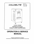
UC-113G/B
Soft Serve Freezer
DOUBLE FLAVOR COUNTER MODEL
OPERATION & SERVICE
3760 Industrial Drive, Winston-Salem, NC 27105
.Telephone:.(919) 661-9893 Telefax: (9.19) 661-9895' Telex:75417OY"
Thank you for selecting Coldelite to meet today's fast growing
demands. Your Coldelitefreaer has been manufactured at one of the
most modem freezer manufacturing plants in the USA., our Lodi,
New Jersey facility, utilizing the most advanced equipment and
technology available in the industry. We, at Coldelite, take great pride
and care in the manufacture of each and every freaer, using only the
finest components available, to provide you with years of trouble-fiee
operation.
Over twenty-fie years of experience in the manufacturing of dispensing
equipment have guided us in the preparation of this Operation and
Service Manual. PLEASE READ IT CAREFULLY. Keep it for fiture
reference and most of all, follow the instructions from the very time
your machine is delivered.
On the following pages, you will illfind important information and
procedures which describe the proper installation, sanitizing, operation
and maintenance of your Coldelite machine. Wefeel certain that your
@11 compliance with these instructions will assure you of excellent
performance, trouble-free operation and a profitable business for
years to come.
Page
FOREWORD ........................................................... 1
PART I
INSTALLATION .................................... 5
.............................................. 5'
............................. 5
...5
..............................6
..........................7
A) Uncrating
B) Positioning the Machine
C) Machines Equipped with Water Cooled Condensers
D) Electrical Requirements
E) Completing the Installation
PART II
EXPLANATION OF CONTROLS ............. 7
..................................7
.............................. 8
............................... 8
................................ 8
........................................ 9
INITIAL CLEANING PROCEDURE........l o
ASSEMBLING THE FREEZER .............14
A) Assembling the BeaterIAugers ..................... 1 4
6) Assembling the Dispensing Head ..................15
C) Assembling the Gravity Feed Tubes ................17
SANlTlZlNG THE FREEZER ................18
STARTING THE FREEZER...................20
OPERATING THE FREEZER ................21
ROUTINE, PERIODIC CLEANING ........22
A) The Selector Switch
6) Low Mix Level Indicator
C) The Dispense Handles
D) Electric Control Panel
E) Other Controls
PART ill
PART IV
<
PART V
PART VI
PART VII
PART Vlll
PART I X
PROCEDURES
TECHNICAL INFORMATION ................ 24
......................................... 24
........................................24
........................................ 25
MAINTENANCE .................................. 25
A) Trouble Shooting Guide ............................ 26
6) Wiring Guide ........................................27
C) Parts Identification .................................. 28
A) Refrigeration
B) Beater Motor
C) Drive System
PART X
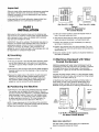
Important
I
orlo
Chute
II
Failure to closely follow operational and maintenance procedures
may result in damage to the unit and/or void your warranty
Coldelite Corporation will not be responsible for any machine
not properly maintained
In the event this unit should malfunction, please contact your
Coldelite Distributor or an authorized service agency
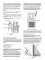
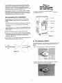
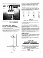
Side View UC-113G(B)
Front View UC-113G(B)
Figure 1
Clearances Required for
Air Cooled Models
Before starting this procedure, make sure the shipping case
does not show any evidence of having been dropped, tampered
with or abused in such a way as to indicate that its contents
may have been damaged in transit
IMPORTANT: Should the outside of the shipping case give any
indication of possible hidden damage, state this on the bill of
lading before signing Contact the carrier immediately and
request an inspection of damage If this procedure is not
adhered to, you will forfeit your right to file a damage claim and
be responsible for subsequent repair costs
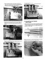
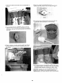
A) Uncrating
Proceed. as follows:
1) The case is secured to the skid with plastic strapping When
you cut this strapping, do it with caution, as it may spring
out Remove case by lifting it straight up and away from the
machine
2) The freezer is also secured to the skid with plastic strapping
Exercise caution and cut this strapping to free the machine
from the skid
3) Remove the single screw at the bottom of each side panel
Remove the panels by sliding upward slightly, then pull
outward at the bottom and allow the panel to slide down.
The protective plastic coating which is laminated to the
panels can now be removed by simply peeling off
B) Positioning the Machine
2) If the unit is water cooled, it should be located within six
feet of the water supply and drain
3) The machine should also be within six feet of the power
supply (a plug and receptacle or unfused disconnect)
4) Position the machine for easy accessibility for cleaning,
serv~cingand maintenance
5) Position the machine away from direct sunlight For every
2°F over 68"F, the machine's performance will decrease by
approximately 1%
6) Once the machine is set in position, it should be leveled as
accurately as possible
C) Machines Equipped with Water
Cooled Condensers
Machines equipped with water cooled condensers must be
connected to a water line (cold) which can maintain a pressure
of at least 35 psi, and a flow rate equal to the estimated
consumption of 1 gallon per minute when the compressor is
running
Connect the fitting marked "water in" to the cold water supply,
preferably with a shut-off valve, and connect the fitting marked
"water out" to the drain (Ref Fig 2)
All plumbing must meet local and state plumbing codes In
some cases, the use of high pressure flexible hose with a
pressure rating of at least 120 psi may be used..This will
facilitate moving the machine for cleaning, maintenance, etc
1) The freezer is now ready to be positioned onto your counter
The counter must be capable of supporting 341 lbs. and
should be vibration free Reinforce it, if necessary Remember
when choosing a location, if your unit is air cooled, proper
air flow will need to be maintained Allow at least 6 inches
on either side and a minimum of 12 inches between the
rear of the machine and any obstruction (Ref Fig 1)
NOTE: I f these clearances are not maintained, the production
capacity will be reduced, cycling will increase and the potential
will exist that the machine will stop completely
Water Inlet
Q
Water
222s {
1
Water Inlet
water out
1J*~
Rear View UC-113G(B)
Water Outlet
/*
Figure 2
1 12" M.P.T. Plumbing Connections
for Water Cooled Models
Water Valve Adjustment
The water valve is preset at the factory. If an adjustment
should be required, proceed as follows:
To maintam a head pressure of 220 psi 2 5 psi, while the
compressor is running, attach a refrigeration high pressure
gauge to the compressor's high side discharge port Open the
valve clockwise to increase the pressure or counter clockwise
to decrease the pressure (Ref Fig 3) This adjustment, if
needed, should be performed by a refrigeration technician
Estimated water consumption is 36 gallons per hour. This
figure will increase if the water temperature is over 68°F
Coldelite freezers are equipped with protection for the beater
motor Should the line voltage drop, or in the unlikely event a
short circuit occurs, the overload protector will automatically
disconnect the starter and the machine will stop immediately
so that no permanent damage can be caused to the motor
I
To restart the freezer, depress the RESET button which is
accessible through an opening at the upper rear panel of the
machine The heaterlprotector must cool down for several
minutes before the RESET will operate (Ref Fig. 4)
Warning!
Reset Button
Never expose a water cooled mach~neto temperatures at or
below 32°F without having first drained the water from the
condenser
r
be blown through the condenser
To dram, hlgh pressure a ~should
from the water mlet while the compressor IS running (so water
valve IS open) Th~soperatron should be performed by a refrigeration techn~cian
If this dramage is not properly performed, serious damage to
the refrigeration system can occur
Adjustment Screw
9
Figure 4
/ ""'
Water Inlet
(Supply)
Water Outlet
(Dram)
The compressor is also internally protected. If the Klixon protector
trips due to an overload, again the protector must first cool
down for several minutes before the compressor can be restarted.
Water Condenser
Figure 3
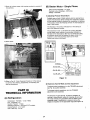
D) Electrical Requirements
All wiring installed to operate this freezer must be in accordance
with the National Electrical Code andlor local electrical codes,
rules and regulations The machine must be properly grounded
It is recommended the power supply be installed by a licensed
electrician.
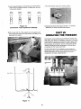
Electrical Connections (Ref. Fig. 5)
Having removed the right side panel, the machine's wiring
connection box can be found on the bottom of the frame and
is labelled "Connect Power Line Here"
The power line is first passed through the access hole located
at the bottom right rear of the machine The line is then passed
through the hole at the bottom deck directly below the wiring
connection box The power line may then be connected to the
machine's power lines and wiring connection box Upon
completion, the power line should be fastened to the wiring
connection box with appropriate electrical hardware, romex or
cable connectors are recommended
Voltage UC113G/B: 220 Volts
Running Amperage FLA: 17.1 Amps
Fuse Size: 30 Amp,.Max..
Wire Size (50 Ft. Max.): #8
Power Supply must be adequate to meet requirements at all
times. Voltage fluctuations, with the machine in operation, should
not exceed f 5% of the normal or rated voltage.
Adequate Wiring must be provided with respect to wire size
or gauge. Unless otherwise required by the local Electrical
Code, the same size wire gauge at the machine junction box
should be used for the direct power line, A separate circuit
breaker with adequate fuse protection should be employed.
t .-
An unfused disconnect switch or a properly sized plug and
receptacle within 6 feet of the freezer, is recommended..
Access for Power Lme
/'
In all installations, the machine must be properly grounded
Since all high voltage components (controls are 24 volts) are
connected by means of flexible conduit, adequate ground
continuity is assured by running and fastening a ground line to
the machine junction box ground lug (Ref Fig 5 )
After electrical connections are completed, check the rotation
of the beater. It should be counter clockwise when facing the
front of the machine If checking from the rear of the machine,
note direction of arrow on fly wheel for rotation
PART I!
EXPLANATION
OF CONTRQLS
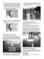
All operator controls are conveniently located at the front of
the machine (Ref Fig 7)
E) Completing the Installation
Selector Switch
Sanitary regulations may require that your counter model
machine be sealed to the counter top. To seal, proceed as
follows:
Dlspenslng Handle
1)Clean the counter top thoroughly to remove any dirt, dust, etc,
Dispensing Head
2) Clean the lower rim, or bottom flange of machine base.
(Ref. Fig. 6)
3) Apply bead (approx 114" wide) of General Electric RN-102
silicone sealant (or equivalent) to the bottom surface of the
machine base
--.
Low MIX 1
lndcator
4) Place the machine on counter in the location chosen
5) Remove any excess sealant by slowly running a flat edged
tool (spackling tool) aroung the base of mounting frame This
will create a seamless joint between the frame and the
counter top (Ref Fig 6)
----
Figure 7
6) Allow sealant to dry thoroughly (refer to sealant manufacturer's
directions) before operating the machine
A) The Selector Switch
The Selector Switch is a four position, four function switch The
positions of the switch along with respective functions are as
follows:
1) OFF -The machine does not operate in this position
Figure 6
\
\-
I
2) AUTO ..This position is used for the continuous production
and dispensing of frozen, finished product
3) ENERGY CONS - Th~sposit~onis used during prolonged,
idle periods. The temperature of the product in both the mix
tank(s) and freezer cylinder(s) is held at a safe temperature
and controlled automatically by the thermostats Product
should never be served when in this position as the "storage"
temperature is higher than normal serving temperatures
with the level of mix The plastic float contains a magnet
which will energize or close the mix level switch at a factory
pre-set position Once closed, the mix level switch energizes
the "low mix level indicator"
The beater motor is not energized in this position which will
allow significant ENERGY CONSERVATION
4) BEATER -This oosition is used only during start-up, cleaning
' and sanitizina drocedures While i
this ~osition,only the
beater motor-is activated All refrigeration circuits are deenergized
C) The Dispense Handle(s)
The Dispense Handle controls the flow, or extraction rate of
finished, soft serve product.
Pulling the handle in a downward direction will open the
dispense orifice When the unit is in the "AUTO" mode, this will
allow finished product to be extracted and served
The downward motion of the handle raises the dispense piston,
opening the dispense orifice The rising motion of the piston,
raises the front micro switch activatmg lever located directly
above the piston At a factory pre-set position, the front micro
switch activating lever will activate the front micro switch
which, when in the "AUTO" mode, energizes the beater motor
B) Low Mix Level Indicator
This light will illuminate when the level of mix in the mix tank
falls below 112 gallon indicating the tank should be refilled
There are two indicators, one each for the left and right mix
tank When illuminated, dispensing of product should be stopped
and the tank refilled with mix Each tank has a total capacity of
two gallons when full
D) Electric Control Panel
The Electric Control Panel located behind the upper rear
panel of the unit, contains the controlling circuit to the components
of the machine This panel is to be accessed only by trained,
experienced technicians
1) The MIX LEVEL SWITCH is located within the stainless steel
rod attached to the bottom of each mix tank A plastic,
"DONUT" shaped float is placed over the rod and will float
Warning
a
Disconnect freezer from the source of electrical supply before
attempting to service
t
Electronic
H..O.M
Beater Motor
Starter
Solenoid
Relay
Timer
Terminal Block
( 220 Volt )
Compressor
Contactor
\
safety
Thermostat
-
\
Terminal Block
( 24 Volt
Tev Mix TankThermostat
Tec Energy Cons.Thermostat
-
The following is an explanation of the control panel controls;
-
I ) COMPRESSOR CONTACTOR activates the refrigeration
compressor When the unit is in the "AUTO" mode, the
compressor contactor can be energized by the electronic
H.O.M., timer, or "TEV" thermostat. In the "ENERGY CONS "
mode, the contactor will be energized by the YEC" thermostat,
2) BEATER MOTOR STARTER -activates the beater/auger
drive motor In the "BEATER" mode, the starter is energized
by the selector switch In the "AUTO" mode, the starter is
activated by either the front micro switch or timer.
3) The TERMINAL BLOCK (220 volt) is the inter:connection
point for high voltage components, i e compressor, transformer, beater motor, and fan motor (when applicable).
4) The SOLENOID RELAY directl; controls the mix tank and
freezer cylinder refrigeration solenoid valves In the "AUTO"
mode, the relay can be energized by the timer, front micro
switch, or by the "TEV" thermostat When in the "ENERGY
CONS" mode, the relay is activated by the thermostats
5) TIMER - is dual purpose,serving as a 10 minute timer and
2 second time delay. In the "auto" mode, the 10 minute
timer activates the beater motor at 10 minute intervals
which allows the ELECTRONIC H 0,M to "checknconsistency
of the product in the freezer cylinder(s). In the event additional
refrigeration is needed to maintain consistency, the 2 second
time delay serves to prevent simultaneous energizing of
the beater motor and compressor
6) The ELECTRONIC HARD-0-MATIC (H.0 M ) automatically
senses and controls product consistency when the unit is
in the "AUT'O" mode. Depending on signals received from
the beater drive system, the H 0 M, activates or stops the
refrigeration system to maintain pre-set product consistency
i
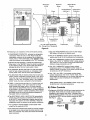
7) The CURRENT TRANSFORMER monitors beater motor
current for the electronic H..OM..
8) The OVERLOAD PROTECTOR senses the current supplied
to the beater motor and will stop the entire machine in the
event of an overload T'his device also houses the overload
reset mechanism
\
I
Overload
Protector
Transformer
Current
Transformer
9) The main TRANSFORMER steps down the line voltage
(220 volts) to 24 volts for the control circuit
10)The 24 volt TERMINAL BLOCK serves as the inter-connection point for all 24 volt controlling circuit components
11) The "TEV"THERM0STAT monitors mix tank temperatures
When in the "AUTO" or "ENERGY CONS" modes, temperature of the mix in the mix tank should never exceed 45°F.
Optimum storage termperature is 40°F
12) The "TEC" THERMOSTAT' monitors freezer cylinder
temperatures when in the "ENERGY CONS." mode. For
optimum results, the product in the freezer cylinder should
be stored at a 28-34°F temperature
13) The "TES 1 and TES 2" thermostats monitors freezer
cylinder temperatures when in the "AUTO" mode. If for
some reason the temperature in the cylinder drop below the
range of the ice cream temperature the compressor is
disconnected.
NOTE: Several hours in the "ENERGY CONS." mode must
be allotted prior to checking temperature.
E) Other Controls
1) Refrigeration SOLENOID VALVES are located behind the left
side panel. These valves are normally closed and when
energized by the solenoid relay, direct refrigerant flow to
either the freezing cylinder or mix tank. The mix tank solenoid
is identified as "EWn and the cylinder solenoid as "EVC"
p,
(Ref. Fig 9)
2) The HIGH PRESSURE CUT-OUT is located on the right side
of the freezer and is tied into discharge or high side line
near the compressor In the event of high pressure situation,
it will shut down the compressor Reset is automatic when
the high pressure subsides Common causes for cut-out or
shut down are restricted air flow on air cooled models,
unusually high ambient (room) temperatures, and restricted
or excessively hot water flow on water cooled models
HELPFUL SUGGESTION: Before proceeding with the
disassembly of the freezer, we recommend a plastic dish
pan be used in which to place the parts This will minimize
the possibility of misplacing or damaging the various
component parts
PART Ill
INITIAL CLEANING
PROCEDILIIWE
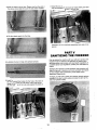
This is a new machine and it must be completely disassembled,
washed, and sanitized before starting Proceed, as follows:
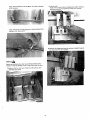
1) Remove the mix tank cover and items packed in the tank
(spare parts, sanitizer, lubricant)
2) Proceed with the disassembly process by removing the two
gravity feed tubes located in the mix tank Snug fitting, the
tubes can be removed by pulling straight up and out
The spare parts or start-up kit will include: 1) a spatula, 2)
spare O-rings and rubber seals, 3) an o-ring extractor, 4) a
tube of sanitary lubricant, 5) three various sized cleaning
brushes. 6)several ~ a c k e t sof sanitizer and the
Once removed, the tubes must be disassembled. To disassemble, first remove the "SPLASH GUARD" by pulling it out
of the tube
Next, remove the gravity tube
"SLEEVE"by pulling it straight
off of the tube
4) Loosen and remove the four (4) dispensing head retaining
knobs The knobs are removed by turning in a Counter.,
clockwise direction.
Finally, remove the o-rings using the O-RING EXTRACTOR
included in the "start-up kit"
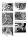
5) Remove the dispensing head by pulling it straight towards
warnin&
Never use anything other than the O-RING EXTRACTOR to
remove o-rings as damage to the o-ring and/or part can result
3) Remove the two mix level "floats" by lifting them off the
stainless steel shaft
6 ) Disassemble the dispensing head by first opening all the
dispense handles
Using the O-RING EXTRACTOR, remove the piston o-rings
Each piston o-ring groove IS notched for easy insertion of
the o-ring extractor
Turn the dispensing head over and remove the two large orings from the back of the head.
Pull the handle retainina rod out far enough
- to allow the
first handle to disenaaae
7) Remove the beaterfaugers from the freezer cylinders Pull
the beaters STRAIGHT out towards you Should they become
jammed, DO NOT' FORCE Tap the front of the beater back
into the cylinder with the palm of your hand
Return the retaining rod to its original position Using the
rod as a fulcrum, lever the dispense piston out of the
dispense head with the handle Repeat this process for
each of the three pistons.
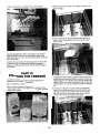
8) Disassemble the beaterlauger by first removing the rubber
beater shaft (lip) seal, simply slide it off the shaft.
10) Wash all the parts in luke warm water (80" - 85°F) using a
mild detergent and the cleaning brushes provided in the
START-UP KIT
DO NOT USE HOT WATER O N ANY OF TWE PLASTIC
PARTS AS DAMAGE TO THE PARTS CAN RESULT
Continue disassembly by removing the beater IDLER Pull
forward until the grooved portion of the shaft lines up with
the opening at the front of the beaterlauger Lift the idler
uo and out
Figure 10
Rinse the parts in luke warm water (80" - 85°F)
Place the parts in luke warm, sanitized water for 2 to 5
minutes Use the sanitizer provided in the START-UP KIT'
following the manufacturers directions
Finally, remove the beaterlauger END PUSHER by pulling
straiqht and away from the beater
9) The machine is now completely disassembled.The parts
should now be washed, rinsed and sanitized.
11) Place the parts on a clean, sanitized counter area and
allow to air dry or assemble wet DO NOT TOWEL DRY OR
RINSE SANITIZED PARTS
PART IV
ASSEMBLING
THEFREEZER
Push the idler back, inserting its shaft into the hole of the
beaterlauaer shaft
Once the parts have been washed, rinsed and sanitized, the
freezer is ready to be re-assembled Prior to beginning the reassembly procedure, sanitize your hands by submerging in the
sanitizing solution Begin to re-assemble as follows:
A) Assembling the Beater/Augers
1) First, re-assemble the beater/auger assembly Begin by
gathering the four parts needed to complete each assembly:
A) plastic "END PUSHER", 6) BEATEWAUGER, C) IDLER, D)
rubber, beater LIP SEAL
When installed correctly, the idler (when turned) should rotate
freely If the idler does not rotate, it is incorrectly installed
and must not be installed into the machine Repeat the
above instructions
4) Next, lubricate and install the beater lip seal by first lubricating
the beater/auger shaft with the lubricant included in the
START-UP KIT Place three, 1/4" beads in equal distances
around the shaft as shown below
Slide the rubber, beater lip seal onto the shaft
2) Aligning the end-pusher slot with the slotted shaft located at
the front of the beater/auger, slide the end pusher onto the
beaterlauger as shown.
3) Next, install the idler. Holding the idler in a horizontal
position, turn the idler until the fins are in an upright position.
Then insert the idler by aligning the thinner portion of the
idler shaft with slot in the end-pusher. Guide the idler shaft
down into the slot.
Lubricate the end of the beater lip seal which is not lubricated
by placing three, 1 1 4 beads in equal distances around the
seal surface as shown below
5 ) Repeat the above procedure for the second beaterlauger
assembly.
Rotate the beaterlauger until you feel the drive shaft engage
and ~ u s the
h beaterlauaer further back to properly seat
6) Finally, insert the beaterlauger into the freezer cylinder
Holding the beaterlauger hor~zontally,slide it straight into
the cylinder until it can go no further
IMPORTANT: Before installing the beaterlauger, make certain
the beater lip seal is in place and the idler is properly
installed.
7) Insert the second beaterlauger Once installed, make certain
the flat portion of the idler is in a vertical position The idlers
should spin freely and are counter weighted to naturally rest
in a vertical ~osition
B) Assembling the Dispensing Head
1) Begin by gathering all the parts necessary to assemble the
dispensing head These parts include: A) two (2), 4" diameter
O-rings, B) the dispending head body, C) the center piston
O-ring, D) four (4), 13/'" diameter end piston O-rings, E)
center piston, F) two (2) end pistons, G) handle retaining
rod, H) three (3) dispense handles.
2) First, remount the end piston O-rings onto the end pistons
Simply roll onto the piston until they drop into the O-ring
notches.
5 ) Insert the two end pistons into the two end chambers of
the dispensing head body making certain to align the
square notch of the piston with the rectangular notch at
the front of the dispense head. Repeat this process with
center piston and center chamber
3) Remount the center piston O-ring onto the center piston
This O-ring and piston are easily identified as they appear
to be two O-rings and O-ring grooves interconnected by
6) Turn the dispense head over and install the two 4 diameter
O-rings into O-ring grooves located in the back of the
head.
4) Once the O-rings have been mounted, liberally lubricate
the area between the two O-rings Place a bead of lubricant
around the entire piston as shown.
Lightly lubricate the O-rings with the sanitary lubricant.
Spread the lubricant on the surface area between the two
O-rings and the O-rings as well This will ensure free
movement of the dispense handles once the head is
completely assembled
7) Affix the dispensing head to the machine Lift the front
micro switch activating lever and slide the dispensing head
onto the four mounting studs Release the activating lever,
the lever should rest vertically atop the pistons
8) Install the dispensing handles Insert the round lobe of the
handle cam into the square notch of the piston. Slide the
retaining rod through the dispense head and cam hole to
secure
10) HAND TIGHTEN the knobs in a crisscross manner as
shown below
C) Assembling the Gravity
Feed Tubes
1) Begin by gathering the parts needed to assemble the gravity
feed tubes These parts include: A) the SPLASH GUARD, B)
two (2) 314" diameter O-rings, C ) the TUBE SLEEVE, and D)
the GRAVITY FEED TUBE.
2) Slide the two (2) 314" O-rings onto the bottom of the gravity
feed tube until they drop in the O-rings grooves
9) Fasten the dispense head to the machine using the four (4)
stainless steel retaining knobs
3) Slide the sleeve onto the tube Please note that the slots in
the sleeve should be at the top of the tube when installed..
7) Install the two (2) mix level floats by simply sliding one each
onto the stainless steel shaft in the mix tank
4) Slide the splash guard into the tube.
The machine is now completely assembled and ready to be
sanitized
PART V
SANlifZlNG THE FREEZER
5) Lubricate the two O-rings with sanitary lubricant.
Prior to starting the machine with your soft serve product, the
machine must be sanitized. The frequency of cleaning and
sanitizing cycles must comply with local health regulations. If
uncertain about local regulations, contact your local Board of
Health
Sanitizing the machine is most important. This procedure will
retard the growth of bacteria and insure excellent test results
on your product when examined by local Health andlor
Agriculture Departments.
6) Insert the assembled tubes into the hole at the bottom of
the mix tank Press the tube down until it seats and the
flange at the base of the tube rests against the bottom of
the mix tank
To begin, you will need a clean pail, sanitizer (sample packets
included in the start-up kit), spatula (included in start-up kit),
and brush (plastic bristle).
1) Mix the sanitizer (2 ounces of Steera Sheen green label or
4) Turn the selector switch to the "OFF" position
equivalent) into a clean pail containing two gallons of warm
water This solution will make a 200 P P M (parts per million)
concentration of chlorine sanitizing solution. Pour the solution
into the mix tanks
5) Using a sanitized soft bristle brush, brush the sides of the
mix tank, and all other product contact areas. Allow the
sanitizing solution to remain in contact with all product
contact areas for three to five minutes
IMPORTANT Do not exceed the formula recommended by the
sanitizer manufacturer as it will not add to its effectiveness.
2) Pull the gravity feed tubes out of the mix tank holes and lay
them down in the tank This will allow the cylinders to
completely fill with the sanitizing solution.
6) Place the clean, sanitized pail under the dispensing head
and open the handles by pulling them in a downward direction
3) Turn the selector switch to the "BEATER" position for 30
seconds
7) Allow the sanitizer to completely drain Close handles
2) Rest the gravity feed tubes upright against the side of mix
tank as shown
3) Pour 1% pints of mix into each mix tank. Allow the mix to
drain into the freezer cylinders. This will properly "prime"
each cylinder
HELPFUL SUGGESTION: When the sanitizer stops flowing,
leave the handles open and turn the selector switch to the
"BEATER" position for two to three seconds to help remove the
last of the sanitizer
CAUTION We recommend the beater/auger be turned as little
as possible during the washing and sanitizing operations
Excessive use will cause premature wear to the beater/auger
and cylinders
Only after the machine has been thoroughly cleaned and
sanitized is the unit ready for production
Start the machine as follows:
1) Pour 1 % pints of liquid mix (soft serve ice cream, ice milk,
frozen yogurt, dietary or non-dairy mix) into a clean, sanitized
measuring container
SUGGESTION: When initially pouring mix into the tank, it is
recommended the dispense handles be opened to allow any
residual sanitizer to be "chased" out by the mix entering the
cylinders Place a cup under the dispense head to catch any
residual sanitizer, 2 3 oz is sufficient to purge the sanitizer
out
-
4) Once the pre-measured 11/2 pints of mix has completely
drained into the freezing cylinders, insert the gravity feed
tubes into the holes at the bottom of the mix tank Make
certain the hole at the top of sleeve and tube are facing
toward the front of the machine and are visible
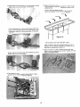
5)Turn the adjustment sleeve of the gravity tube until the medium
sized hole for moderate production is aligned with the hole
in the gravity feed tube
Mln~mum
Prcduct~on
Moderate
Product~on
Max~mum
Prcductlon
7)Turn the selector switch to the "AUTO" position
Energy
Conservatton
Figure 12
Gravity Feed Tube Adjustment Settings
6) Fill the tanks with mix Total capacity is two (2)gallons each
Never fill the tanks higher than the bottom of the slots in the
gravity feed tube sleeve
8) Initial freeze-down of the product will take 7.10 minutes
dependent on the type of product being frozen
PART VII
OPERATING THE FREEZE
The machine will automatically shut-off when the product has
been frozen to the pre-set "consistency" After the 7-10 minute
initial freeze-down period, you will hear the beater/auger drive
motor shut down indicating the product is ready to be served
The compressor will continue to run for a short period as the
machine automatically directs refrigeration to the mix tanks
immediately after the freeze-down cycle
To serve, simply place a cup, container or cone under the
dispensing spout and slowly pull the dispensing handle down
As the product begins to flow, move the cup or cone in a
circular fashion to create a tapering tower
Air Intake
Max Fill Level
-
Mix Intake
*
Figure 11
When the portion is the size you want, close the handle and
pull the cup or cone straight down to add a peak
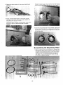
The outer tube is actually a valve Rotating it from hole to hole
on the outer tube varies the size of the hole and the amount of
mix that flows into the freezing cylinder The size of the air
inlet, at the top of the tube, does not change so the amount of
air that enters the freezing cylinder is constant
You can vary the overrun (yield) by letting more or less mix
enter the freezing cylinder by manually regulating the valve
You must align the mix inlet holes on both the inner and outer
tubes or no mix will enter the cylinder You can see this hole at
the top of both tubes See illustration below
Mlnlrnum
Product~on
Moderate
Production
Maximum
Product~on
Energy
Conserval~on
Figure 12
Gravity Feed Tube Adjustment Settings
Typical portion sizes are: SMALL = 3 OUNCE SERVING
MEDIUM = 5 OUNCE SERVING
LARGE = 7 OUNCE SERVING
-
Gravity Feed Valve How to
Operate and Make Adjustments
The Gravity Feed Valve consists of two tubes, one sliding inside
the other, and a plunger/splash guard
The inner tube blends the flow of air and mix into the freezing
cylinder. Air enters through the top of the tube and the mix,
through a round hole at the base See illustration below
I
Alr Intake
Max Fill Level
-
.---------
MIX Intake
\
t
The plunger/splash guard keeps the mix from splashing on the
mix tank cover and serves as a device to eliminate potential
clogging inside the tubes
You may find it necessary to adjust the position of the outer
tube in order to regulate the amount of mix entering the
freezing cylinder after start-up Actually, sales conditions will
dictate the proper adjustment
If more production is required, increase the opening by rotating
the outer tube to a larger hole, and conversely when business
is slow, rotate to a smaller hole on the outer tube, reducing the
opening. Naturally, when the mix runs low in the mix tank, you
will open the slot more and eventually take the feed tube out
completely to use the last of mix in the mix tank
Energy Conservation
During long idle periods, it is recommended the outer sleeve of
the gravity feed tube be rotated to the position which closes
the mix intake hole completely
IMPORTANT. Remember to rotate the outer tube to the appropriate opening before switch~ngto the AUTO mode
PAW'?'VUIS
ROUTINE, PERlODIC
CLEANING PROCEDURES
Cleaning and sanitizing schedules are governed by your State
or local regulatory agencies and must be followed accordingly
A well planned cleaning schedule will eliminate excessive
waste of time and product within your organization.
On a designated day(s) of the week, allow the mix in the mix
tank to run as low as feasible.
d\
Figure 11
Proceed to clean the machine, as follows:
i
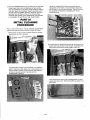
1) Remove the Gravity Feed Tubes Pull the tubes straight up
and out
4) When the product has stopped flowing, turn the Selector
Switch to the OFF position Close the spigot handle
5 ) Fill hopper(s) and cylinder(s) with cold water (a mild, nonfoaming dish washing detergent is recommended)
2) Turn the Selector Switch to BEATER position and let the
machine run for 4 to 5 minutes Th~swill soften the product
in the cylinder and allow the remaining product to be removed
more easily
3) Place a container or bucket under the spigot head. Slowly
pull the handle down and remove remaining product from
6) Turn Selector Switch to the BEATER position for one minute
Turn Selector Switch to OFF position, drain water by opening
the spigot handle Repeat this process until water is clear
IMPORTANT: Operate unit only in the BEATER position when
cleaning. Do not operate unit for excessive periods in the
BEATER position, one minute intervals per rinse is recommended
7) Brush all surface areas, with brushes prov~ded,to remove all
mix particles
-
(B) Beater Motor Single Phase
H.0 M. cutout Amperage - 7 6 Amps
Overload cutout Amperage - 8.5/9 Amps
Voltage 208-230V
-
1
1) Adjusting Product Temperature
Coldelite uses a Hard-0-Matic system which is referred to as
H 0 M. This electronic device controls the refrigeration system
for the freezing cylinder by 'sensing' the consistency or hardness
of the product inside the freezing cylinder No thermostats are
used in this system
The firmness of the product will depend on the setting of
the H O.M. electronic control
The compressor must cut off when the current, absorbed
by the beater motor, reaches the amperage indicated on
the label in the electrical box (B/N Cut-Out Amps). By using
an ammeter across the line feeding the beater motor, it is
possible to check the amperage drawn by the motor
Factory pre-cutout is 8 0 Amps
8) Drain Water:
9) Refer to Part Ill, "Initial Cleaning Procedure" of this manual
to continue the cleaning, disassembly, re-assembly, and
start-up procedures
2) Electronic Hard-0-Matic Control Adjustment
To reduce product consistency, turn the TRIMMER adjustment,
(see Fig 13) counter clockwise
PART IX
TECHNICAL INFORMATION
(A) Refrigeration
-
Compressor - Hermetic - 1 5 hp R502
FLA ..Amperage 6 7
Suction Pressure -. 18 psig
Discharge Pressure .. 225 psig @75"Fambient
Coolinq System - air or water
Use ~ 5 0 only
2 - 2.2 Ibs.
-
To increase product consistency, turn the TRIMMER
adjustment screw clockwise
The electronic H.0 M (see Fig 13) has the possibility of
working in three different ranges of amperage. Be sure that
the range selected is in accordance with the beater motor
amperage range. If modification is required, remove the
bridge and reposition on the appropriate range. (See Figure 13)
.
Overload Protector
T25DU 7.5/11
3)
UC-113G
PART X
MAINTENANCE
Calibration
8 Amps
Energy conservation
i
Models equipped with this feature allow the operator to
switch to a more economical circuit during limited service
During this mode of operation, the product and hopper
temperature are controlled thermostatically The beater motor
is de-energized resulting in a substantial reduction in power
input
a) How to Operate
The life expectancy of a machine, any machine, does not
depend only on the quality of its components and design, but
also on the benefic~aleffects of basic maintenance procedures
It is important to you, therefore, to become familiar with a few
of these basic procedures:
Turn Selector Switch to ENERGY CONSERVATION The
beater motor is completely de-energized and the temperature
of the product in the freezing cylinder is controlled by the
thermostat (TEC),which is set approximately at a temperature
of 28°F - 30°F
3) Lubricate all '0' rings and seals, as instructed
Mix Tank Refrigeration
4) The wearing or the improper cleaning of the beater and the
The mix tank is provided with a refrigeration system, thermo.
statically controlled (TEV)
a) How to Adjust the Mix Tank Temperature
The thermostat (TEV) has been preset at the factory to
maintain a mix temperature ranging from 35" F to 40°F The
reading is taken at the center of the mix tank
1) Remove '0' rings only with the ' 0 ' ring extractor supplied
with the machine
2) Clean the machine according to the instructions
pump shaft seals, will result in leakage from the rear Check
the drip chute pans frequently and replace seals, when
necessary
5) Replace any '0' rmg that has a nick in it If not replaced, it
will leak and interfere with the proper performance of the
machine
In the event further adjustment should be required, proceed
as follows:
6) When all the spare parts supplied with the machine are
used, re-order immediately Do not wait until the part is
required again
Mix tank too warm -Turn thermostat screw a half turn,
clockwise.
7) NEVER use the AUTO position for washing, sanitizing and
initially filling the freezing cylinder
Mix tank too cold . Turn thermostat screw a half turn,
counter clockwise
8) IMPORTANT During the washing and sanitizing period, run
the machine only for the time strictly necessary for this
operation Prolonged use of the beater in the Cleaning
position may cause severe damage to the machine
Remember you will have frost on the mix tank walls so for
any adjustment beyond a one half turn in either direction,
wait at least two hours to observe results
-
9) Always wash metal, plastic or rubber parts in lukewarm
water NEVER, NEVER USE HOT WATER!
(C) Drive System
Important
The rotation of the beater is counter clockwise and is motivated
by a belt drive system
If your Model UC-1 13G is an air cooled machine, its efficiency
depends on the air cooled condenser The fins of the condenser
must be cleaned every two or three months to assure efficiency
-
Spigot Switch How It Operates (See Fig E, Pg 31)
A micro switch (MIR), located in the housing directly above the
spigot head assembly, actuates the beater motor whenever the
dispensing handle is pulled down to draw product The Selector
Switch must be in the AUTO position
I
Your COLDELJTE machine has been designed, engineered and
manufactured to achieve high performance and long durability
The actuating lever is preset at the factory
How to Adjust the Front Micro Switch
Should it become necessary to take the assembly apart for any
reason (see Fig E), proper calibration must be maintained The
micro switch must engage and start the beater motor before
the product is dispensed from the head To calibrate, look
through the opening at the bottom of the spigot head. Slowly
pull the dispensing handle down to raise the piston in the
spigot head The micro switch must be activated (you will hear
the click) before you can see the product opening (orifice)
inside the head If this opening shows before you hear the
click, the adjustment screw must be raised Loosen the lock
nut under the adjustment screw and turn the screw counter
clockwise Retighten the nut after this adjustment
Warning
Extreme care must be taken when removing side, rear or
control box panels
Always turn the Selector Switch to the OFF position Also, turn
off the Disconnect Switch on the electrical supply line before
exposing any electrical connections and/or moving parts, such
as belts, pulleys, fan blades and beater
TROUBLE SHOQTWG GUIDE
Problem
Possible Cause
Suggested Remedy
1) Product too soft
a) Drawing faster than machine can
produce
b) H 0 M control out of calibration or
malfunctioning
c) Machine short of freon gas
a) Slow down draw rate
b) Contact authorized service agency
c) Contact authorized service agency
2) Nothing comes out of dispensmg head
a) No mix or low mix in mix tank
b) Feeding tube setting not sufficiently
opened
a) Add mix to mix tank
b) Adjust gravity feed tube sleeve to larger
opening
3) Machme will not freeze
a) Restricted air or water flow
b) Compressor not working
C)Short of freon gas
d) Malfunctioning torque control (H 0 M )
e) Malfunctioning starter
f) Insufficient power supply
a) Remove obstruction or restriction
b) Contact authorized service agency
c) Contact authorized service agency
d) Contact authorized service agency
e) Contact authorized service agency
f ) Contact authorized service agency
4) Machine runs continuously
a) Dispense handle not completely closed
b) Front micro switch stuck in ON position
c) 10 minute timer stuck in ON position
d) Short of freon gas
e) Restricted or excessively warm air or
water flow
a) Close handle
b) Readjust or replace front micro
c) Contact authorized service agency
d) Contact authorized service agency
e) Remove obstruction or restriction
5) Beater motor fiumming
a) No mix in cylinder
a) Refer to #2) above
6) Beater motor will not shut off
a) Front micro switch activated or stuck
a) Refer to Item #4) above
7 ) Machine will not start
a) No power to machine
b) Malfunctioning selector switch
c) Off on overload
a) Check plug, disconnect switch or fuses
Push reset button
b) Contact authorized service agency
c) Push reset button after waiting for reset
to cool
8) Short cycle on machine
a) Going off on high pressure
a) Clean condenser (air cooled models)
b) Malfunctioning Klixon on compressor
C)Check water flow
9) Machine smoking
a) Drive belt is slipping
b) Cylinder starved
a) Turn off machine and tighten belt
b) Reset mix intake tube to add more mix
to cylinder Turn machine OFF Put
selector switch on BEATER for one
minute Return to AUTO position
Resume normal o~eration
10) Mix drips from rear of head assembly
a) "0" ring missing or has a split
b) Head not tight
a) Install or replace "0" ring
b) Tighten hand knobs
11) Low overrun
a) Defective "0" ring Check all "0" rings
b) Too much liquid in cylinders
a) Replace any worn or damaged "0" ring
b) Close liquid hole in feeding tube, draw
several portions and reopen hole
-
i
WIRING DIAGRAM
-
CR Rotary Selector Switch
EVC Cylinder Solenoid Valve
EVV Mix Tank Solenoid Valve
IML Magnetic Switch - Mix Level
HOM Hard-0-Matic Torque Control
LSL Lamp - Mix Level Indicator
-
-
-
MA Beater Motor
MC Compressor Motor
MIR Front Microswitch
MV Fan Motor
PR Pressure Control
R 1 Auxiliary Relays
TRA Current Transformer
-
-
-
-
RTA Overload Protector - Beater Motor
TEC Energy Cons Thermostat
TEV Mix Tank Thermostat
l T A Beater Motor Contactor
l T C Compressor Contactor
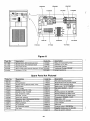
TR Transformer 230124V
TZF Tirnerflirne Delay
TES Safety, Low Temp Thermostat
-
-
-
Figure A
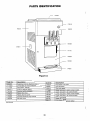
Code No.
1654200
171 1 030*
171 1150
17201 71 *
1 7201 90
1745210
1745460
1745550
1750702
*Not p~ctured
Description
Retaining knob for dispense head
24 Volt Bulb for mix fill indicator
CapILense Orange
Knob for selector switch
Selector switch-complete
Plastic drip chute
Plastic drip tray cover
Stainless steel drip tray bracket
Mix tank cover
-
Code No.
1780350*
1902220
19032lo*
1904280*
1904290*
1905240*
1905250*
1906250
1906260
555631 0*
Description
Front decal - std. color
Left side panel
Right side panel
Upper rear panel - water cooled models
Upper rear panel air cooled models
-
Lower rear panel - water cooled models
Lower rear panel air cooled models
Lower front panel
Upper front panel
Front decal - self service Option
-
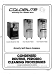
PARTS IDENTBFICATION
- 1785040
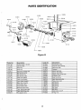
Figure B
Code No.
1411 190
141 1 290
1518170
1518180
1610010
1610120
1610180
1610240
161 1100
1611120
161 2020
161 2030
161 2380
161 2390
161 2600
1613120
1613160
161 501 0
Description
Rubber beater. lip seal
Gear box seal
Snap ring
Snap ring
Bushmg for tension arm
Belt tension spring
Belt tension arm
Belt tension pulley
Plastic rear gasket
Plastic front gasket
Cover, trans. housing
Base, trans. housing
Dnve pulley, trans.
Driven pulley, trans.
Bushing, driven pulley
Trans. shaft, driven side
Trans. shaft, drive side
Ring spacer, trans.
-
Code No.
161 5020
1615130
1616020 1618270
1638070
1638120
1638200
1640400
1664010
1664100
1708290
1785040
1785090
1785270
1914150
1914190
3201 260
341 0300
Description
-
Ring spacer, trans.
Ring nut, trans. housing
Seal, dr~veshaft
Flywheel
Gravity feed tube
Gravity tube sleeve
Splash guard, gravity tube
2E beater, short
Float, mix fill ind.
Stem, float control S/s
Pulley, drive motor
Ball bearlng
Ball bearing
Ball bearing
Belt. trans.
Belt, drive
Drive motor, 1.8H.P.
O-ring, 1 13
-
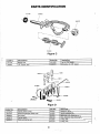
PARTS IDENTIF1CATION
1641600
Figure C
Code No.
141 1190
1640400
Description
"
Beater seal
"2E"Beater, seal
Code No.
1641 600
1642070
Description
Idler, for "2E" beater
End pusher, for "2E beater
i
Figure D
Code No.
141 1240
1651230
1652020
1652070
1653080
Description
Center piston O-ring
Dispensing/Spigot heady body
End piston
Center piston
Piston activating cam
Code No.
1653270
1654030
1654200
1654330
341 0090
3410210
Description
Dispense Handle
Handle retaining rod
Retaining knob, dispense head
Stud, dispense head retaining
O-ring, 342
O-ring, 21 5
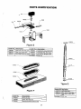
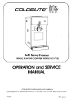
PARTS IDENTIFICATION
Figure E
Code No. Description
1680080
1680120
1680230
Nylon pin, front micro cam 1680260
Cam, front micro switch
1680300
Pivot shaft, front micro cam 1720260
35 18080
-
Adjustment screw, front micro
Activating lever, front micro
Microswitch, Burgess e BR
Snap ring
Figure G
Figure F
Code No.
1 745200
1 745460
1745550
D
escription
Front drip tray
Cover, front drip tray
Bracket/Console, front drip tray
Figure H
Code No.
Description
Code No.
1711520
1711530
1723100
1723750
1724350
Terminal block, 220V (individual block)
Terminal block, 24V (individual block)
Timer, fiber 24 Volt
Hard-o-matic torque control, electronic 24 Volt
1
Contractor, 24 Volt
1724620
1724680
1725110
32?3080
3213500
Description
Relay, mini-mod 55/34 24 Volt
Overload, 7.511 1 Amp.
Thermostat, Danfoss
Transformer, Dongan 230/24V
1 Current transformer
Spare Parts Not Pictured
I
,
Code No.
Description
Code No.
Description
1540130
1540140
1720070
1720370
1723770
1724400
1724621
1724800
1727270
1727280
1727570
1727800
1730010
1731210
1731290
1740120
Spatula
O-ring extractor
Rubber seal for selector switch 1720...
Reset button
1740340
1745320
1990430
3201260
32031 10
3250120
3250370
3250440
3250450
3301290
3304100
3304280
3305150
3305210
3306390
3310100
3540110
Fan motor mounting bracket
Button/screw, front drip tray bracket
Rubber cover, expansion valve
Beater motor, 1.8 H.P., 208/230/1
Fan motor, 230/60/1 - 1/6 H.P.
Klixon
Running capacitor for 3301290
Starting capacitor for beater motor
Running capacitor for beater motor
Compressor, 220160/A, 1.5 H.P.
Water valve 3 / 8
Valve rotolock for 3301290
Liquid indicator
Filter dryer
Pressure control 2501380 Ibs.
Capacitor & relay assy. for 3301290
Petro-Gel sanitary lubricant
Auxiliary contact for 1724...Socket for relay 1724620
Coil, 24 Volt for 17272...
Solenoid - 24 Volt
Valve body, solenoid
Expansion valve thermostatic, Danfoss
Nozzel #2 for 17275..
Water condenser
Air condenser
Air condenser shrowd
Fan blade
-
-
-
-
t,