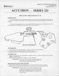
1
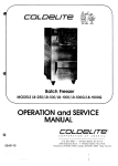
Soft Serve Freezer
DOUBLE FLAVOR COUNTER MODEL
OPERATION & SERVICE
MANUAL
COLDELITE CORPORATION OF AMERICA
3760 INDUSTRIAL DR. * WINSTON-SALEM, N.C.27105 * TEL.(910) 661-9893 * FAX (910) 661-9895
File: 820-1.pm5
Ed. 02/98
FOREWORD
Thank you for selecting COLDELITE to meet today's fast growing
demands. Your COLDELITE freezer has been manufactured at one of
the most modern manufacturing plants, utilizing the most advanced
equipment and technology available in the industry.
We at COLDELITE, take great pride and care in the manufacture of
each and every freezer, using only the finest components available, to
provide you with years of trouble-free operation.
Over twenty-five years of experience in the manufacturing of
dispensing equipment have guided us in the preparation of this
Operation and Service Manual.
PLEASE READ IT CAREFULLY.
Keep it for future reference and most of all, follow the instructions from
the very time your machine is put into service.
On the following pages, you will find important information and
procedures which describe the proper installation, sanitizing, operation,
and maintenance of your COLDELITE machine.
We feel certain that your full compliance with these instructions will
assure you of excellent performance, trouble-free operation and
profitable business for years to come.
All fechnical dafa, pictures and drawings contained in this manual are not binding on the manufacfurer, nor can
the manufacfurer be held liable for any modification of the machine in part or complefely.
CODE: ...... ........
File: 820-1.pm5
Ed. 02198
INDEX
FOREWORD ..........................................................................................3
PART I .INSTALLATION .....................................................................5
A)
B)
C)
D)
E)
F)
UNCRATING ............................................................................................... 5
POSITIONING THE MACHINE ...................................................................... 5
MACHINE EQUIPPED WITH AIR COOLED CONDENSER .......................... 6
MACHINE EQUIPPED WITH WATER COOLED CONDENSER ................... 6
WATER VALVE ADJUSTMENT ..................................................................... 6
ELECTRICAL REQUIREMENTS ................................................................... 7
CONTROL PANELS ....................................................................................... 7
ELECTRICAL CONNECTIONS ...................................................................... 8
BEATER ROTATION ...................................................................................... 8
COMPLETING THE INSTALLATION ............................................................. 8
PART II .EXPLANATION OF CONTROLS .............................................. 9
A)
B)
C)
D)
E)
F)
ELECTRONIC CONTROL PANELS ............................................................... 9
THE DISPENSE HANDLES ......................................................................... 11
PROXIMITY SWITCHES .............................................................................. 11
ADJUSTING PROXIMITY SWITCHES ........................................................ 11
SAFETY SWITCH ........................................................................................ 12
ELECTRIC CONTROL PANEL .................................................................... 12
OTHER CONTROLS .................................................................................... 12
PART Ill .INITIAL CLEANING PROCEDURE ....................................... 13
A)
B)
C)
D)
CLEANING PROCEDURE ...........................................................................
DESMOUNTING DISPENSING HEADS ......................................................
DESMOUNTING BEATER AUGER .............................................................
CLEANING OPERATIONS ...........................................................................
13
15
17
18
PART IV .ASSEMBLING THE FREEZER ............................................. 19
A)
C)
ASSEMBLING THE BEATER ....................................................................... 19
MIX PUMP ASSEMBLING ........................................................................... 24
PART V .SANITIZING THE FREEZER .................................................. 25
PART VI .STARTING THE FREEZER ................................................... 27
HOM ADJUSTMENT (AUTOMATIC) ..................................................................... 28
PART VII .OPERATING THE FREEZER ............................................... 29
A)
B)
C)
STAND BY .................................................................................................... 29
CONE COUNTER ........................................................................................ 29
ADJUSTING THE PUMP FOR OVERRUN .................................................. 30
PART Vlll .ROUTINE. PERIODIC CLEANING PROCEDURES ............ 30
PART IX .TECHNICAL INFORMATION ............................................ 32
A)
B)
C)
COMPRESSOR MOTOR ............................................................................. 32
BEATER MOTOR .SINGLE PHASE ........................................................... 32
OVERLOAD .................................................................................................. 32
PART X .MAINTENANCE ....................................................................32
A)
B)
File: 820- 1.pm5
Ed . 02/98
TROUBLE SHOOTING GUIDE .................................................................... 33
ALARMS ....................................................................................................... 35
IMPORTANT!
Failure to closely follow operational and maintenance
procedures may result in damage to the unit andlor void your
warranty. Coldelite Corporation will not be responsible for
any machine not properly maintained.
In the event this unit should malfunction, please contact your
Coldelite Distributor or an authorized service agency.
PART I
INSTALLATION
B)
POSITIONING THE MACHINE
1) The freezer is equipped with four pivoting wheels to
allow easy location.
When the freezer is placed in the desired location, it
must stand level.
Check for level condition by placing level on the top
of the freezer at each corner.
Lock wheels to prevent freezer sudden movements.
NOTE: Accurate leveling is necessary for correct drainage of
freezer barrel and to insure correct over-run.
Before starting this procedure, make sure the shipping case
does not show any evidence of having been dropped, tampered
with or abused in such a way as to indicate that its contents
may have been damaged in transit.
IMPORTANT:
Should the outside of the shipping case give any indication
of possible hidden damage, state this on the bill of lading
before signing.
Contact the carrier immediately and request an inspection of
damage.
If this procedure is not adhere to, you will forfeit your right to
file damage claim and be responsible for subsequent repair
costs.
A)
UNCRATING
Proceed, as follows:
The case is secured to the skid with metal strapping.
When you cut this strapping, do it with caution, as it
may spring out.
Remove case by lifting it straight up and away from
the machine.
The machine is also secured to the skid with metal
strapping. Exercise caution and cut this strapping to
free the machine from the skid.
Remove the single screw at the bottom of each side
panel. Remove the panels by sliding upward slightly,
thenpull outward at the bottom and allow the panel to
slide down. The protective plastic coating which is
laminated to the panels can now be removed by
simply peeling off.
File: 820-1.pm5
Ed. 02/98
C)
MACHINE EQUIPPED WlTH AIR COOLED
CONDENSER
1) The freezer is now ready to be positioned.
Machines with aircooled condenser must be installed
no closer than 2 FT to any wall in order to allow free
air circulation around the condenser (Ref. Fig. 1).
NOTE: An insufficient air circulation affects operation and
output capacity of the machine.
D)
MACHINE EQUIPPED WlTH WATER
COOLED CONDENSER
1) If the unit is water cooled, it should be located close
to the
water supply and a drain within six feet.
2) Connect fitting marked "WATER IN" to the cold water
supply.
Connect the fitting marked "WATER OUT" to a drain
(see Fig.2).
NOTE: All plumbing must meet local and state codes.
Fig. 2
WATER VALVE ADJUSTMENT
The water valve is preset at the factory, but if an adjustment
should be required, proceed as follows:
To maintain a head pressure of 225-235 psi while the
compressor is running, attach a refrigeration high pressure
gauge to the compressor's high side discharge port, and
open the water valve clockwise to increase the pressure or
counter clockwise to decrease the pressure (Fig.3).
NOTE: If these clearances are not maintained, the
production capacity will be reduced, cycling will increase
and the potential will exist that the machine will stop
completely.
2) It is necessary to clean the condenser each month to
eliminate dust, paper, etc. which may obstruct it,
damaging the proper functioning of the machine.
3) The machine should also be within six feet of the
power supply (a plug and receptacle or unfused
disconnected).
Fig. 3
4) Position the machine for easy accessibility for
cleaning, servicing and maintenance.
5) Position the machine away from direct sunlight.
For every 2°F over 68"F, the machine's performance will decrease by approximately 1%.
File: 820- 1.pm5
Ed. 02/98
Never expose water cooled machines to temperature at or
below 32" F. without having drained the water from the
condenser.
If drainage is not done properly, serious damage can occur.
E)
ELECTRICAL REQUIREMENTS
All wiring installed to operate this freezer must be in
accordance with the National Electrical Code andlor local
electrical codes, rules and regulations.
The machine must be properly grounded.
It is recommended the power supply be installed by a
licensed electrician.
Voltage:
Total Running Amperage FLA:
Fuse Size:
Wire Size (50 Ft. Max.):
CONTROL PANELS
NOTICE: As the machine is equipped with two control
panels, check which panel signalled the alarm.
To restart the freezer, depress the STOPIRESET button
located on the front switch pad.
The heater protection must cool down for several minutes
before the RESET will operate. See Fig. 4.
2081230 Volt
38 A
32 A
A WG 12x2
Power Supply must be adequate to meet requirements at all
times. Voltage fluctuations, with the machine in operation,
should not exceed 4 5% of the normal or rated voltage.
Adequate Wiring must be provided with respect to wire size
or gauge. Unless otherwise required by the local Electrical
Code, the same size wire gauge at the machine junction box
should be used for direct power line.
A separate circuit breaker with adequate fuse protection
should be employed.
An unfused disconnected switch or a properly sized plug and
receptacle within 6 feet of the freezer, is recommended.
Coldelite freezers are equipped with protection for the beater
motor.
Should the line voltage drop, or in the unlikely event a short
circuit occurs, the overload protector will automatically
disconnect the starter and the machine will stop immediately
so that no permanent damage can be caused to the motor.
@ AUTOMATIC
@ STAND-BY
@ BEATER
@ MIX LEVEL
Fig. 4
File:820-1.pm5
Ed. 02/98
ELECTRICAL CONNECTIONS
F)
Having removed the front side panel, the machine's wiring
connection box can be found on the bottom of the frame and
is labelled "Connect Power Line Here".
The power line is first passed through the access hole
located at the bottom deck directly below the wiring
connection box.
The power line may then be connected to the machine's
power lines and wiring connection box.
Upon completion, the power line should be fastened to the
wiring connection box with appropriate electrical hardware.
COMPLETING THE INSTALLATION
On the following pages, you will find important information
and procedures which describe the proper installation,
sanitizing, operation and maintenance of your COLDELITE
machine. We feel certain that your full compliance with these
instructions will assure you of excellent performance,
trouble-free operation and a profitable business for years to
come.
NOTICE: Failure to closely follow set-up and maintenance
procedures can void your warranty. Coldelite Corporation
will not be responsible for any machine not properly
maintained.
In the event this unit should malfunction, please contact your
Coldelite Distributor or an authorized service agency.
WARNING: EXTREME CARE MUST BE TAKEN WHEN
REMOVING SIDE, REAR OR CONTROL BOX PANELS.
Fig.5
In all installations, the machine must be properly grounded.
Since all high voltage components (controls are 24 volts) are
connected by means of flexible conduit, or cord, adequate
ground continuity is assured by running and fastening a
ground line to the machine junction box ground lug (Fig. 5).
BEATER ROTATION
After electrical connections are completed, check the
rotation of the beater.
It should be counter clockwise when facing the front of the
machine.
File: 820- I .pm5
Ed. 02/98
ALWAYS TURN THE MACHINE TO THE OFF POSITION.
ALSO TURN OFF THE DISCONNECT SWITCH ON
ELECTRICAL SUPPLY LINE BEFORE EXPOSING ANY
ELECTRICAL CONNECTIONS AND/OR MOVING PARTS,
SUCH AS BELTS, PULLEYS, FAN BLADES AND BEATER.
PART II
EXPLANATION OF CONTROLS
A)
ELECTRONIC CONTROL PANELS
Leds L l i L 4 Lighted function indicators
These indicators illuminate to show that the function
corresponding to the signal next to the indicator itself is on.
Leds L5 Low level indicator
This led illuminates to show the hopper is empty and you
must refill it with mix.
Monitor pos. 570
This numerical monitor displays the consistency of the
product when the machine is operating in AUTOMATIC.
STOPIRESET button pos. 571. I
L2
AUTOMATIC
L3
STAND-BY
L4
BEATER
w
RESET
With the StopIReset function on, pilot light pos. L1 lit, the
machine is ready to receive the command for any of the
main functions.
SELECT button pos. 571.2
L5
MIX LEVEL
THE MACHINE IS EQUIPPED WITH TWO ELECTRONIC,
INDEPENDENT CONTROL PANELS HAVING THE SAME
FUNCTIONS.
EACH PANEL CONTROLS ONE SIDE OF THE MACHINE.
By pushing this button you can select the functions:
-Automatic
-Stand-by
-Beater
Indicators illuminate to shown that the function
corresponding to the signal next to the indicator itself is on.
File: 820-1.pm5
Ed. 02198
AUTOMATIC
~5
AUTOMATIC
I
Automatic function
Hopper Mix level indicator
When this function is on, pilot light pos. L2 lit, the mix is
This pilot light pos. L5 indicates that the level of the mixin
cooled down until it reaches the proper consistency (pre-set
the hopper has reached the minimum allowed, and that
HOT setting).
more mix must be added.
During this function, the Monitor displays a number indicating A buzzer will be on when light is on.
the consistency of the product in the cylinder until it reaches
the set value, then it indicates the temperature of the mix in
When illuminated, dispensing of product should be stopped
the hopper tank.
and the tank refilled with mix.
Each tank has a total capacity of 32 qts each when full.
The MIX LEVEL SENSOR is located in the hopper of each
mix tank (see Fig.7).
STAND-BY
Stand-by function
This position is used during prolonged idle periods.
The temperature of the product in both the mix hoppers and
freezer cylinder is held at a safe temperature and controlled
automatically by the temperature probes.
Product should never be served when in this position, as the
"storage" temperature is higher than normal serving
temperatures.
When this function is on, pilot light pos. L3 lit.
When pushing this button, the beater motor and the cooling
motor are ON until the product temperature reaches the
programmed temperature.
If the machine runs in stand-by mode for a prolonged
period, the product temperature is kept constant
automatically.
In such condition, the cooling motor is ON whereas the
beater motor is OFF.
~4
BEATER
I
Beater function
With this function on, pilot light pos. L4 on, only the beater
turns.
This function is timed and ends automatically when the set
time is over (about 15 minutes).
File: 820- 1.pm5
Ed. 02/98
Mix level
sensors
B)
THE DISPENSE HANDLES
The Dispense Handles control the flow, or extraction rate of
finished, soft serve product.
The left handle serves a flavour of product, the right one
serves a different flavour whereas the midle one dispenses
a mix of the two.
Pulling one of the handle in a downward direction will open
the corresponding dispense orifice.
When the unit is in the "AUTOMA TIC" mode, this will allow
finished product to be extracted and served.
C)
PROXIMITY SWITCHES
In AUTOMATIC function, the proximity switches pos. 152
start the beater motors when the hand, handling cup or
cone, is in the range of the sensitivity preset by Coldelite.
Note: Keep the sensors always clear and clean.
ADJUSTING PROXIMITY SWITCHES
The proximity switches pos. 920 (Fig.9) have been preset at
the factory and their range is 9-14 inches approx.
If modification is required, contact authorized service agency
as this operation must be carried out by specialized
technicians.
File:820-1 .pm5
Ed. 02/98
D)
SAFETY SWITCH
Machine is equipped with a magnet molded into the spigot
head. If the spigot head is removed the magnet deactivates
a safety switch behind the front panel. The machine will not
operate with the spigot head removed.
Alarm AL9 will appear on the display.
E)
ELECTRIC CONTROL PANEL
The Electric Control Panel located behind the bottom front
panel of the unit, contains the controlling circuit to the
components of the machine.
This panel is to be accessed only by trained, experienced
technicians.
A Warning /i\
Disconnect freezer from the source of electrical supply
before attempting to service.
F)
OTHER CONTROLS
1) Refrigeration SOLENOID VALVES are located
behind the left side panel.
These valves are normally closed and when
energized by the electronic board, direct refrigerant
flow to either the freezing cylinder or mix tank.
The mix tank solenoid is identified as "EVV and the
cylinder solenoid as "EVC".
2) The HIGH PRESSURE SWITCH.
In the event of high pressure situation, it will shut
down the compressor.
Reset is automatic when the high pressure subsides.
Common causes for cut-out or shut down
arerestricted air flow on air cooled models, unusually
high ambient (room) temperatures, and restricted or
excessively hot water flow on water cooled models.
File: 820- 1.pm5
Ed. 02/98
PART Ill
INITIAL CLEANING
PROCEDURE
A Warning /j\
A)
CLEANING PROCEDURE
1) Proceed with the disassembly process by extracting
connection pipe from the pump (Fig.10).
Slightly turn pressure pipe and extract it from its seat.
Connection
During all following operations unplug the machine so
as to cut it out.
This is a new machine and it must be completely
disassembled, washed, and sanitized before starting.
Proceed, as follows:
- Remove the mix tank cover and items packed in the
tank (spare parts, sanitizer, lubricant).
The spare parts or start-up kit will include:
1)
2)
3)
4)
5)
6)
a spatula
spare o-rings and rubber seals
an o-ring extractor
a tube of sanitary lubricant
three various sized cleaning brushes
several packets of sanitizer and the OPERATIONAL
MANUAL.
HELPFUL SUGGESTION:
Before proceeding with the disassembly of the freezer, we
recommend a plastic dish pan be used in which to place the
parts.
This will minimize the possibility of misplacing or damaging
the various component parts.
2) Turn the pump slightly and extract it from its seat
(Fig.1 I ) .
3) Clean carefully the mix level sensor (Fig.1 I ) .
File: 820-2.pm5
Ed. 02198
4) Remove all pump components as shown in the
picture below.
File: 820-2.pm5
Ed. 02/98
B)
DESMOUNTING DISPENSING HEADS
3) Disassemble the dispensing head by first opening all
the dispense handles.
1) Loosen and remove the six (6) dispensing head
retaining knobs.
The knobs are removed by turning in a counterclockwise direction.
4) Pull the handle retaining rod out far enough to allow
the first handle to disengage.
2) Remove the dispensing head by pulling it straight
towardsyou and away from the machine.
5) Return the retaining rod to its original position.
Using the rod as a fulcrum, lever the dispense piston
out of the dispense head with the handle.
Repeat this process for each piston.
File:820-2.pm5
Ed. 02198
6) Using the O-RING EXTRACTOR, remove the piston
o-rings.
Each piston o-ring groove is notched for easy
insertion of the o-ring extractor.
Now the dispensing heads is completely dismounted (see
Fig.19A)
Dispensing heads parts:
A)
B)
C)
D)
E)
F)
G)
H)
I)
7) Turn the dispensing head over and remove the two
large o-rings from the back of the head.
File:820-2.pm5
Ed. 02/98
two (2), 4" diameter O-ring
the dispensing head body
the center piston O-ring
four (4), 13/,., diameter end piston O-rings
center piston
two (2) end pistons
handle retaining rod
three (3) dispense handles
one (1) handle retaining rod O-ring
C)
DESMOUNTING BEATER AUGER
1) Remove the beaterlaugers from the freezer
cylinders.
4) Continue disassembly by removing the beater
IDLER.
Pull forward until the grooved portion of the shaft
lines up with the opening at the front of the beater1
auger.
2) Pull the beaters STRAIGHT out towards you.
Should they became jammed, DO NOT FORCE.
Tap the front of the beater back into the cylinder with
the palm of your hand.
5) Finally, remove the beaterlauger END PUSHER by
pulling straight and away from the beater.
Dismount the scraper by pulling it away from its
housings.
Disassemble the beaterlaugers by first removing the
beater stuffing box (lip) seal, simply slide it off the
shaft.
Stuffing box
The machine is now completely disassembled.
The parts should now be washed, rinsed and sanitized.
File: 820-2.pm5
Ed. 02/98
D)
CLEANING OPERATIONS
1) Wash all the parts in lukewarm water (80-85" F)
using a mild detergent and the cleaning brushes
provided in the START-UP KIT.
DO NOT USE HOT WATER ON ANY OF THE PLASTIC
PARTS AS DAMAGE TO THE PARTS CAN RESULT.
2) Rinse the parts in luke warm water (80-85" F).
3) Place the parts in luke warm, sanitized water for 2 to
5 minutes.
Use the sanitizer provided in the START-UP KIT
following the manufacturers directions.
4) Place the parts on a clean, sanitized counter area
and allow to air dry or disassemble wet.
DO NOT TOWEL DRY OR RINSE SANITIZED PARTS.
4) Air Dry
File:820-2.pm5
Ed. 02/98
PART IV
ASSEMBLING THE FREEZER
2) Mount the rubber seal onto the scraper by keeping
the head opposite to the groove.
Once the parts have been washed, rinsed and sanitized, the
freezer is ready to be re-assembled.
Prior to beginning the re-assembly procedure, sanitize your
hands by submerging in the sanitizing solution.
Begin to re-assemble as follows:
A)
ASSEMBLING THE BEATER
1) First, re-assemble the beaterlauger assembly.
Begin by gathering the five parts needed to complete
each assembly:
A)
B)
C)
D)
E)
F)
Plastic end pusher
Beater
Idler
Beater stuffing box
Blade
Rubber spacer
0
Fig.26
3) Insert the scraper into the beater pins.
4) Fasten the end pusher.
When installed correctly, the scraper should move
freely up and down, but should not come out away
from its seat.
5) Mount the idler back.
File: 820-2.pm5
Ed. 02/98
6) When installed correctly, the idler (when turned)
should rotate freely.
If the idler does not rotate, it is incorrectly installed
and must not be installed into the machine.
Repeat the above instructions.
7) Next, lubricate and install the beater stuffing box1 by
first lubricating the beater shaft with the lubricant
included in the START-UP KIT.
Place three, 114" beads in equal distances around
the shaft as shown below.
11) Finally, insert the beaterlauger into the freezer
cylinder.
Holding the beaterlauger horizontally, slide it
straight into the cylinder until it can go no further.
Rotate the beaterlauger until you feel the drive shaft
engage and push the beaterlauger further back to
properly seat.
IMPORTANT:
Before installing the beaterlauger, make certain the beater
lip seal is in place and the idler is properly installed.
8) Slide the rubber, beater lip seal onto the shaft.
12) Insert the second beaterlauger.
Once installed, make certain the flat portion of the
idler is in a vertical position.
The idlers should spin freely.
'
9) Lubricate the end of the beater lip seal which is not
lubricated by placing three, 114" beads in equal
distances around the seal surface as shown below.
10) Repeat the above procedure for the second beater
assembly.
File: 820-2.pm5
Ed. 02/98
B) Assembling the dispensing head
1) Begin by gathering the parts necessary to assemble
the dispensing head.
These parts include:
two (2), 4" diameter O-rings
the dispensing head body
the center piston O-ring
four (4), 13/,,, diameter end piston O-rings
center piston
two (2) end pistons
G) handle retaining rod
H) three (3) dispense handles
I) one (1) handle retaining rod O-ring
A)
B)
C)
D)
E)
F)
File:820-3.pm5
Ed. 02/98
2) First, remount the end piston O-rings onto the end
pistons.
Simply roll onto the piston until they drop into the
O-ring notches.
5) Spread the lubricant on the surface area between the
two O-rings and the O-rings as well.
This will ensure free movement of the dispense
handles once the head is completely assembled.
3) Remount the center piston O-ring onto the center
piston.
This O-ring and piston are easily identified as they
appear to be two O-rings grooves interconnected by
two vertical posts.
5) Insert the two end pistons into the two end
chambers of the dispensing head body making
certain to align the square notch of the piston with
the rectangular notch at the front of the dispense
head.
Repeat this process with center piston and center
chamber.
Fig.35
4) Once the O-rings have been mounted, liberally
lubricate the area between the two O-rings.
Place a bead of lubricant around the entire piston as
shown.
File: 820-3.pm5
Ed. 02/98
Fig.38
6) Turn the dispense head over and install the two 4"
diameter O-rings into O-ring grooves located in the
back of the head. Lightly lubricate the O-rings with
the sanitary lubricant.
7) Affix the dispensing head to the machine and fasten
it onto the six mounting studs.
8) Fasten the dispense head to the machine using the
six (6) stainless steel retaining knobs.
9) HAND TIGHTEN the knobs in a criss-cross manner
as shown below.
File: 820-3.pm5
Ed. 02/98
C)
MIX PUMP ASSEMBLING
Grease all gaskets before placing them to their
positions.
Take pump body pos. 1 and grease gear seats.
Assemble gears pos. 414A and OR gaskets pos. 2
and also lubricate pump surface.
Assemble cover pos. 3, clamp the pumps with knobs
pos. 5 and OR gasket pos. 6.
Place valve pos. 7 and spring pos. 8 in their seats.
OR gaskets pos. 9 must be assembled onto the
regulator pos. 10 before placing the latter into pump
cover.
Turn the regulator by 45" C at least, in order to
secure it to the proper lock position.
Assemble OR gasket pos. 11 onto the connection
pipe pos. 12.
Assemble OR gasket pos. 13 on pressure pipe pos.
14 or 15.
10) Last reassemble seal valve pos. 16 and pos. 17
File:820-3.pm5
Ed. 02/98
A wrong or not fully proper assembling of the individual
components prevents the pump from sucking as sufficient
quantity of mix from the tank, so damaging the beater.
The pump may not operate if spring and valve acting as
safety devices against overpressures have been removed
from the regulator.
PART V
SANITIZING THE FREEZER
Prior to install the machine with your soft serve product, the
machine must be sanitized. The frequency of cleaning and
sanitizing cycles must comply with local health regulations.
If uncertain about local regulations, contact your local Board
of Health.
Sanitizing the machine is most important. This procedure will
retard the growth of bacteria and insure excellent test results
on your product when examined by local Health andlor
Agriculture Departments.
To begin, you will need a clean pail, sanitizer (sample
packets included in the start-up kit), spatula (included in
start-up kit), and brush (plastic bristle).
2) Push selector button 571.2
PUSH TOI
II SELECT
I
to select
the BEATER position.
I
B BEATER
3) Let the machine run for 30 seconds.
This will allow the cylinder and the pump to be
completely filled with the sanitizing solution.
4) Push selector button 571. I
"OFF" the machine.
5) Using a sanitized soft bristle brush, brush the sides of
the mix tank, and all other product contact areas.
Allow the sanitizing solution to remain in contact with
all product contact areas for three to five minutes.
1) Mix the sanitizer (2 ounces of Steera Sheen green
label or equivalent) into a clean pail containing two
gallons of warm water.
This solution will make a 200 P.P.M. (parts per
million) concentration of chlorine sanitizing solution.
Pour the solution into the mix tanks.
IMPORTANT:
Do not exceed the formula recommended by the sanitizer
manufacturer as it will not add to its effectiveness.
6) Place the clean, sanitized pail under the dispensing
head andopen the handles by pulling them in a
downward direction.
File: 820-4.pm5
Ed. 02/98
7) Press the blead plunger, and make pressure release.
Extract connection pipe from the pump.
Then, slightly turn pressure pipe and extract it from
its seat in order to drain upper tank and cylinder.
HELPFUL SUGGESTION:
When the sanitizer stops flowing, leave the handle open.
Push selector button 571.2 to select the BEATER position.
Let the machine run for three, four seconds to help remove
the last of the sanitizer.
CAUTION:
We recommend the beaterlaugers be turned as little as
possible during the washing and sanitizing operations.
Excessive use will cause premature wear to the beater1
augers and cylinders.
Fig.44
7) Allow the sanitizer to completely drain.
Close the handles.
File: 820-4.pm5
Ed. 02/98
Clean and sterilize the machine as described in chapter
8 daily or every few days, taking into account the
bacteriological quality of your mix and your local health
regulations.
If the machine has stopped due to a power failure, it is
essential that you check the mix temperature before
dispensing ice cream.
If it has heated up to 43°F. the machine must be cleaned
and sterilized, and filled with new mix at 39°F.
PART VI
STARTING THE FREEZER
5) Insert the connection pipe into the pump and leave in
this position about 30".
Only after the machine has been thoroughly cleaned and
sanitized is the unit ready for production.
Start the machine as follows:
1) Insert the compression pipe into its housing on the
bottom of the tank.
Install pump shaft and pump: do not install
connecting tube.
Fill the tank with mix. Total capacity is 32 qts each.
Temperature of mix should be not more than 44°F.
1'
6) Push the button STOPIRESET
I
I
STOP
RESET .
I
7) Bleed the excess air pushing in the blead plunger.
2) Push selector button 571.2
I PUSH TOI
I SELECT 1
to select
8) Adjust the sleeve position to obtain a flow of mix in
the cylinder, according to the thickness of the mix.
the "BEATER" position.
1
6 BEATER
9) Push selector button
3) Check pump efficiency: the mix will flow out the
cover outlet.
1'
4) Push the button STOPIRESET
STOP
I
I RESET^
IPUSH TOI
ISELECT 1
pos. 571.2 to
select the "AUTOMATIC" position.
The machine will automatically perform the setting as
programmed by the manufacturer. When setting is
over the display will show hopper temperature, for
instance: 40" F., now you can dispense the soft
serve product.
SUGGESTION:
When initially pouring mix into the tank, it is recommended
the dispense handle be opened to allow any residual
sanitizer to be "chased" out by the mix entering the cylinder
Place a cup under the dispense head to catch any residual
sanitizer, 2-3 oz. is sufficient to purge the sanitizer out.
File: 820-4.pm5
Ed. 02198
11) When this function is on, pilot light L2 lit, the product
is cooled down until it reaches the proper
consistency according to the HOM calibration.
~2
AUTOMATIC
I
During this function the monitor displays a number
indicating the consistency of the product in the
cylinder until it reaches the set value, then indicates
the temperature of mix in the hopper.
Initial freeze-down will take 7-10 minutes depending
on the type of mix used.
Note: in spite of the fact that the machine is equipped with
two hoppers and two corresponding cylinders, each hopper
and cylinder can work independently.
HOM ADJUSTMENT (AUTOMATIC)
pos. 571. I
Push the button STOPIRESET
selector button
ISELECT
I
pos.571.2 simultaneously;
the display will show "Stl" and then the programmed value of
the HOM.
Normally the HOM is set to 100.
The regulation can vary from 50 to 120 by pushing on
PUSH TO
selector button
pos.571.2
Once the HOM is set to the desired value, do not push the
button again, the display will flash 3 times and then returns to
the normal functioning mode.
File: 820-4.pm5
Ed. 02198
PART VII
OPERATING THE FREEZER
The machine will automatically shut-off when the product
has been frozen to the pre-set "consistency".
After the 7-10 minute initial freeze-down period, you will
hear the beaterlauger drive motor shut down indicating the
product is ready to be served.
The compressor will continue to run for a short period as the
machine automatically directs refrigeration to the mix tanks
immediately after the freeze-down cycle.
To serve, simply place a cup, container or cone under the
dispensing spout and slowly pull the dispensing handle
down.
As the product begins to flow, move the cup or cone in a
circular fashion to create a tapering tower.
When the portion is the size you want, close the handle and
pull the cup or cone straight down to add a peak.
A)
STAND BY
During long pauses in ice servings, press button pos. 572.2
"PUSH TO SELECT to select "STAND BY". You will save
significantly on energy consumption, as the compressor runs
only for the amount of time strictly necessary in order to
keep the mix at the proper temperature.
When you want to begin serving, press button pos. 572.2
"PUSH TO SELECT" to select "AUTOMATIC" again.
After only a few minutes the ice cream will be at the correct
hardness for sale.
IMPORTANT:
Remember to lift the outer tube to the appropriate opening
before switching to the AUTO mode.
I
PUSH TO
sELEc+
AUTOMATIC
STAND-BY
BEATER
Typical portion sizes are:
MIX LEVEL
SMALL = 3 OUNCE SERVICING
MEDIUM = 5 OUNCE SERVICING
URGE = 7 OUNCE SERVICING
Dispense the ice cream without exceeding the machine's
production rhythm as indicated in the table on page 34.
If you do not exceed this pace and are careful to refill the
machine with fresh mix, you can be sure you will never have
to pause in selling ice cream, even during peak times.
B)
CONE COUNTER
The number of cones delivered is memorized in the program
area. This number is the cumulative number of cones
extracted since the machine has been delivered to the
customer. This number can not be reset by the user. To read
this number we must have the machine in STOP, push the
"STOP" and "PUSH TO SELECT" simultaneously for 3
seconds.
Push "STOP" button 2 more times.
You get on the display "CtH" and the value of thousand of
cones extracted.
By pushing one more on the "STOPJ'button the display
shows "CtL" and the value of the number of cones
extracted. By releasing all buttons, the display will flash 3
times and then return to the normal functioning mode.
Example:
20351 cones will be illustrated as:
CtH 020
CtL
351
File: 820-4.pm5
Ed. 02/98
C)
PART VlH
ROUTINE, PERIODIC
CLEANING PROCEDURES
ADJUSTING THE PUMP FOR OVERRUN
Overrun can be adjusted within a value range of 40% to
loo%, by turning suction pipe lever.
To increase overrun, turn the lever right (looking at machine
front side).
To decrease overrun, turn the lever left (here, too, looking at
machine front side).
Cleaning and sanitizing schedules are governed by your
State or local regulatory agencies and must be followed
A well planned cleaning schedule willeliminate
excessive waste of time and product within your
organization.
On a designated day(s) of the week, allow the mix in the mix
tank to run as low as feasible.
Note:
In order to make the reading of low level indicator easier,
rinse it with vinegar or scales remover.
Proceed to clean the machine, as follows:
1) Press selector button
ISELECT
(
pos.571.2 so
as to enter CLEANING mode.
2) Locate a bucket under the spigot head. Pull down the
handle and slowly empty the cylinder until pressure
is completely released.
The product will be softened and will run out
completely fluid.
3) Now press STOP and remove tank cover.
4) Bleed the excess air pushing in the blead plunger.
5) Extract the tube and place it into a container filled
with warm water.
File: 820-4.pm5
Ed. 02198
6) Remove pump and place it into a container pail and
rinse all parts.
8) Cleaning may be performed also on one single
hopper, however, during cleaning, do not remove the
spigot head.
9) Refer to Part Ill, "Initial Cleaning Procedure" of this
manual to continue the cleaning, disassembly,
re-assembly, and start-up procedures.
7) Pull up the handle.
Pour luke warm in the tank and with a sponge clean
additional residues.
Enter CLEANING mode.
Pull down the handle and let water completely drain
until1 both tanks are empty.
File: 820-4.pm5
Ed. 02/98
PART IX
TECHNICAL INFORMATION
COMPRESSOR MOTOR
Compressor - Hermetic
78A
RLA - Amperage
Suction Pressure
17 bar
Discharge Pressure (2001230)
Cooling System
Air
Use R 404 only
3,5 Ibs
Refrigeration - Mix Tank Automatic Valve
Suction Pressure
1 bar
Cylinder capacity
3,6 qts
Tank capacity
30,6 qts
-
BEATER MOTOR 3-PHASE
H.O.M. cutout Amperage (230 Volt) = 6.2 A
Overload cutout amperage max 6,6 A
Voltage
2081230 Volts
Beater rotation: counter clockwise - (machine front view)
OVERLOAD
T 25
Calibrated
6 - 8,5 A
6,6 A
The beater motor overload is controlled by the front switch
pad.
The mode of the overload is in AUTOMATIC, if the overload
trips off, wait a few minutes and reset the overload pushing
the "STOPIRESET" button on the front switch pad.
PART X
MAINTENANCE
Your COLDELITE machine has been designed, engineered
and manufactured to achieve high performance and long
durability.
The life expectancy of a machine, any machine, does not
depend only on the quality of its components and design,
but also on the beneficial effects of basic maintenance
procedures.
It is important to you, therefore, to become familiar with a
few of these basic procedures:
Remove O-rings only with the O-ring extractor
supplied with the machine.
Clean the machine according to the instructions.
Lubricate all O-rings and seals, as instructed.
The wearing or the improper cleaning of the beater
shaft seals, will result in leakage from the rear.
Check the drip chute pans frequently and replace
seals, when so necessary.
Replace any O-ring that has a nick in it. If not
replaced, it will leak and interfere with the proper
performance of the machine.
When all the spare parts supplied with the machine
are used, re-order immediately. Do not wait until the
part is required again.
NEVER use the AUTO position for washing,
sanitizing and initially filling the freezing cylinder.
IMPORTANT - During the washing and sanitizing
period, run the machine only for the time strictly
necessary for this operation. Prolonged use of the
beater in the Cleaning position may cause severe
damage to the machine.
Always wash metal, plastic or rubber parts in
lukewarm water. NEVER, NEVER USE HOT
WATER!
IMPORTANT:
If your Model is an air cooled machine, its efficiency
depends on the air cooled condenser. The fins of the
condenser must be cleaned every two or three months to
assure efficiency.
Warning
//\
Extreme care must be taken when removing side, rear or
control box panels.
Always turn the Selector Switch to the OFF position.
Also, turn off the Disconnect Switch on the electrical supply
line before exposing any electrical connections andlor
moving parts, such as belts, pulleys, fan blades and beater.
File: 820-4.pm5
Ed. 02/98
A)
I
TROUBLE SHOOTING GUIDE
Problem
Possible Cause
Suggested Remedy
1) Product too soft.
a) Drawing faster than machine can
produce.
b) H.O.M. control out of calibration or
malfunctioning.
c) Machine short of Freon gas.
a) Slow down draw rate.
b) Contact authorized service agency.
c) Contact authorized service agency.
2) Nothing comes out of
dispensing head.
a) No mix or low mix in mix tank.
b) Feeding tube setting not sufficiently
open.
a) Add mix to mix tank.
b) Adjust gravity feed tube sleeve to
larger opening.
3) Machine will not freeze.
a)
b)
c)
d)
e)
f)
a)
b)
c)
d)
e)
f)
4) Machine runs
continuously.
a) Short of Freon gas.
b) Restricted or excessively warm air.
a) Contact authorized service agency.
b) Remove obstruction or restriction.
5) Beater motor humming.
a) No mix in cylinder.
a) Refer to #2) above.
6) Machine will not start.
a) No power to machine.
a) Check plug, disconnect switch or
fuses.
Push reset button.
b) Contact authorized service agency.
c) Push reset button after waiting for
reset to cool.
d) Control if spigot head is properly
assembled.
Restricted air flow.
Compressor not working.
Short of Freon gas.
Malfunctioning torque control (H.O.M.).
Malfunctioning starter.
Insufficient power supply.
b) Malfunctioning control panel.
c) Off on overload.
d) Safety switch not energized.
Going off on high pressure.
7) Short cycle on
machine.
3)
8) Mix drips from rear of
head assembly.
2) O-ring missing or has a split.
1) Head not tight.
9) Low overrun.
2)
Defective O-ring. Check all O-rings.
I) Too much liquid in cylinders.
Remove obstruction or restriction.
Contact authorized service agency.
Contact authorized service agency.
Contact authorized service agency.
Contact authorized service agency.
Contact authorized service agency.
a) Clean condenser (air cooled
models).
b) MalfunctioningKlixon on compressor.
c) Check water flow.
a) Install or replace O-ring.
b) Tighten hand knobs.
a) Replace any worn or damaged O-ring.
b) Close liquid hole in feeding tube,
draw several portions and reopen
hole.
File: 820-4.pm5
Ed. 02/98
Machine
model
UF 820 E
TRONIC
File: 820-4.pm5
Ed. 02/98
Weight
Width
Ibs
inc
Depth
~nc
Height
Installed
power
Tank
capacity
Hourly
output
inc
Kw
qts
Ibs
13,4
30,6+30,6
99
B)
ALARMS
Control push-buttons are completely independent.
The alarm appearing on a display refers to that control pushbutton.
The machine is equipped with a self-checking device which
signals faults in the machine.
The right figure point on the display is the "Check Led".
"Check Led" flashes in case of alarm and keeps on flashing
to catch operator's attention.
After resetting the alarm, the led stops flashing.
Push STOP button to read the last alarm.
When "Check Led" is ON (or flashes), check the fault in the
table and if necessary, call the technician.
In case the intervention of a technician is necessary, push
STOP button onlv once so as to read the last alarm shown,
and inform the technician. The machine can run in
PRODUCTION mode even if an alarm is ON; however if the
alarm is a dangerous one, the machine does not enter the
PRODUCTION mode. In such condition, press STOP button
and do not switch on the machine until its repair.
When more than one alarm is activated simultaneously, the
alarm shown is the last one activated.
When more than one alarm are active, see the following
order:
IMS
RTA
TEV
TEC
TGV
TE 1
ICE
TE2
.
RESET
I
I
/
PUSH TO
SELECT
@ AUTOMATIC
@ STAND-BY
@@ BEATER
@ MIX LEVEL
AL9
ALI
AL5
AL6
AL7
AL3
AL8
AL2
The table below shows the alarms available:
ALARMS
DESCRIPTION
AL 1(RTA)
Overload beater motor tripped
YES
AL2(TE2)
Alarm for right cylinder cooler outlet sensor
(bi-cylindrical only)
YES
Probe TEI out of order
YES
Probe TEV (hopper) out of order
YES
Probe TEC (cylinder) out of order
YES
Probe TGV out of order
YES
Cylinder ice sensor alarm = -27°C (+5"F)
TEl or TEC low temperature mix in the cylinder
YES
Safety magnetic switch (spigot head opened)
NO
AL9(I MS)
(flashing point)
CALL TECHNICIAN
File: 820-4.pm5
Ed. 02/98
File: 820-4.pm5
Ed. 02/98