1
r
TAN DON MAGNETICS CORPORATION
9333 050 AVENUE
CHATSWORTH, CALIFORNIA 91311
(213l 993·6644
MANUAL PIN 171024
'anaon
TM 100 DISK DRIVE
OPERATING & SERVICE MANUAL
PROPRIETARY NOTICE
Information contain!!'d in this document is copyright by TANDON
MAGNETICS CORPORATION and may nOt be duplicated in lull
0( in part by any person without prior written approval of TAN DON
MAGNETICS CORPORATION. It is ptovid!!'d as an aid to the USer
with no guarantee. written 0 ( impli!!'d, that the document is accur.te
with rO'gard to any ,peellkation.
"copyright 1979 T ANDON MAGNETICS CORPORATION
TABLE OF CONTENTS
SECTION I
GENERAL DESCRIPTION AND SPECIFICATIONS.
Introduction
Purpo.e ot Equipment
PhY.;CIII D&SCription of Equipment
Functional
Description ... Di.kenes .
Mechanical end Electrical SpecHiClltion• . . Interhsce Specifications.
Uncrating the Disk Drive
. Phy.ical Checkout
Interface Connection. .
Chessis Ground .
Mounting the Di.k Drive
D;skene Handling and Storage
Loading the Diskelle
. Write
Protect. . DC Power Requirement<.
SECTION II
,
THEORY OF OPERATION.
Introduction ... O,ganization of fhe Disk Drive ... Functional Block Diagram Description .. Inde~.
Write ProtllCt
Track 00 Switch
. Spindle Drive.
Pos;tioner Control.
Data ElllCtronic.
SECTION III
OPERATION.
Introduction. . Physical Description of PCBA·, .
Board T...t Poin" ... Option Select ... Adjustment
"
Interface Electronics Specifications ... Circuit
LIST OF ILLUSTRATIONS
Figure
Figure
Figure
Figure
Figure
Figure
Figure
Figure
Figure
Figure
Figure
Figure
Figure
Figure
FilllJre
1
2
3
4
5
6
7
8
9
10
11
12
13
14
15
TM 100 Oi.k Orive :
Recording Medium.
Outline TM100 Oi.k Drive.
Diskette Care and Handling.
Diskette Ae<:...
Write Prot&ct Tab.
TM100 Functional Block Diagram
FM Recording
Write Timing Diagram
Read Timing Diagram
Logic P.C.B.A.
Servo P.C.B.A.
Interface Configuration.
Catseye Pallern.
Inde~ to Dala
LIST OF TABLES
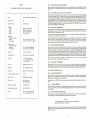
Table 1
Table 2
Table 3
Mechanical and Eleclfical Specification•.
Int"factl Conne<:tor Pin A..ignmenli, JI!P1
Power Connector Pin Anignment.
,,,
,,
"""
"""
.""
"
6
•
TI""
SCME
•
50 .",,10'.
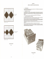
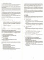
INDEX TO DATA
Fig. 15
3.6.2 TRACK
ee SWITCH
(1) Apply the nec"l'Sary power end cont,ol to turn on th, drive.
1211nse" lhe CE Alignment Diskette into the drive end close the 1'0111 latch.
j31 Position lhe ca"iege to the r&diel alignment trado. Confirm the position by observing lhe cat...ye
panern.
(4) If adjustmell1 is required, remove the CE Diskeue. LOOMn the retaining screw on lhe bese of the
Track 00 8racket, retighten slighUy to provide some friction on the bracket end rotate the Track
I!II!1 Adjustment $c'ew (located at Ihe ,ear of lhe chassi,) counter""lockwise ., fe' 81 it will gO
without forcing il.
(5) Po.ition the carriage to Track 01.
(6) Rotate Ihe Track 00 Adjustmerl1 Screw clockwise-very ,lowly-until Ihe switch "cliCks", Th,n
rotate Ihe screw clockwise (same direction) .~ac!ly one-hell turn.
111 Ti!toten the retaining screw PIIrviously loosened.
3.6.3 WRITE PROTECT SWITCHES
(1) Insert a non .....rite prOlteled diskette partially (halfway) into the drive.
(21 Ensure that Ihe switch ;$ actualed.
(3) In$ert diskene fully ogainSI disketlO back Slop end dow Ihe fronl letch. Ensure that the switch iJ
da!lCti""led.
(4) Adjust Jwitch by l00$8ning Ihe retaining screw. removing $witch a""embly and $etting switch higher
or lower as required.
3,6.4 DRIVE MOTOR SPEED
(1) Apply nec8U8ry power end control 10 lurn on Ihe dri"".
(2) Inwt diskeill.
(3) Ensure thai Drive Motor Enable line i$ !!Clive.
(4) Adjust Speed Conlrol potenliomel... (on servo PCBAl untill;ming di$k ;s slalionary in fluorescent
lighling.
SECTION I
GENERAL DESCRIPTION AND SPECIFICATIONS
1.1
INTRODUCTION
Thi. Metion prOYideI the phy.iul Ind functio....1 specilicltions for !he TM100 Di.... Drivi. manulllCwred by
TANDON MAGNETICS CORPORATION.
1.2
PURPOSE OF THE DRIVE
Thl TM100 Di.k Drive i. B "MINI" Disk MBfTlory d..igned for random lICC.... dati Intry. ltorage. and
retrieval Ipplication•. Th"'llPplicllion. typically Irl int.lligent terminal controllt<"1. micro-eomputlrl. word
ptoc.... ing .... II.,-nl. datil communic:ltion. IVStern•• error logging, mic.P-prOliJram loading, and point of sale
terminal•.
The TMIOO Is capable 01 'lCO<di"lllnd .eading digitlll dttl using FM. MFM. or M2 FM tlChniqutl.
1.3
PHYSICAL DESCRIPTION OF THE DRIVE
oWe ern..
ilihown in Figure I. The Orn.. can bt mounted in 1"Y.-ticIl or horizontll pie.....;
t>owev., whtn mounted horizonully. t", orinnd c;_it logic boa<d mull bt UjlpImIOst.
TlM TMl00
st_
Tht spinell. II btIt dri'ien by I de motor with .. intlgr'll tlChomtt.... Thl _
eontrol ci<cuit. lUitlbly.izId
pulley•. Ind thII tlChometl< control thII '1-.:1 of thl lPinelll. The .ead!_ite doubl.....idsl I>ttd u-nbly iI
pos.itionld by m ..... 01.
motor, split band. and I wiUobly sized pulltY.
~'M'
KAcS • '"
Th, read/write/"I" head aatmbly is , g1lll1-bondtd I... rite/ceramic structure which hn I IIII in excess of
20.000 hOUri.
-'M'
Operator ace... lor di.kette 10ldlng 1s prcwided y1a I .Iot located at thl from of the unit.
The electronic components 01 thl Drivi are mounttd on tWO PCBA<•• onl 01 which (IOl1ic) i.locattd tbovl
th, cha..i•• thl other (...rvol i. mounttd Itlh, rNr of thl un't. POWI' and Inlerface .ignals.re .outtd through
connectors which plug directly into thl logic PCBA.
(lfOO"_.......
B~
" MIL 0« T~ACXI
CATSEYE PATTERN
Fill. 14
TM 100 DISK DRIVE
FJo. 1
1.4
FUNCTIONAL DESCRIPTION OF THE DRIVE
Tha Di'k Drive is fully self"'Con1llined and requires no operatOr inte'VentlOo dudng oormal Opafll!ion. The
Drive cOnliltl cl a spindle drive Iystem. I head po,itioninglYltem. and read!write!erne IYltem.
When the frol1-t latch 11 opened, 8CCeSl il provided for the inltlrtioo of a diskette. The diskelle il positionlld in
place by pla$li'c llUioes, end the front letch. In/out locatiOn il ensured -when the di'kette is in...rted until a
back Itop il encountl"d.
Closing the froont latch activetes the cone/clamp IYltam relUlting in centering of the dilkette and clamping 01
the di,kette t", the drive hub. The drive hub il driven at a constant speed 01 300 rpm by a lerva controlled de
moto" In ope..ation, tha mognetic head is loaded into contact with the recording medium whenever tha front
latch il cloud.
The magnetic titlad i' positioned o""r the desired trock by mean, of a 4-pha1e ltappar motor/band assembly
Ind ItI Inociat:ed aloctronici. This positioner employs a onHteP rOtation to ClUte a l·track linear mOl'flTleot.
When I _ite-protected dill<811e il inserted into the Od"", the write-prOtecl sensor di .. bl ... the write
electronics of ,he OriVI Ind ao appropriate lignal il &pplied to the interface.
Whan parformi "9 e _ite operatloo, a 0,33 mm (0.013·inch) (nominal) data track il recorded. Thlo track io
then tunoel
to 0,30 mm 10.012 inch) (nominal).
In a multipla ddva Iyltam (prOOfam ""unt position "MX" opanl the three input Ii,," (Drive Salect I,
Drive Select 2 and Drive Select 31 Sfe provided 10 that the uling rylt"", may select which drive on the
interfllee il to be uled. In addition, Dri"" Select 4 il provided as an option, In thil mode 01 operation, only
the Drive with itl Drive $elect line active will respond to the input lintland gate the output Ii,,".
The program .nunt, IC location lE. positions "OSl". "OS2" and "DS3". ara to be uled to 1elect which
Drive $elect Ii .... will lIetivate the I/O lines fOf a uniqua drive. As an axample, if the user wantlthe first drive
on the interface to be addressed al drive #1. he mUlt cut program Ihunt positionl "OS2" and "OS3". and
leave "OSl" inUlet.
The prOg<llm .nunt il AMP part number 435704-7, The shuntpo,ition, can be cut uling AMP', tool part
numbOf 435105. The .nunt i, i",1IIlIed in a dip socket. At the userl oPlloo, it can be removed!replaclld by e
dip ,witch. The user may allO choose to heve the program .nunll preprogrlmmed and/or color coded by
AMP. For thll service. con\3Ct your local AMP representative.
3.6
ADJUSTMENT
Oat. recovary electronics Include. 10....I.val read ampllfi.... differentiator. zero-crOlllng detector, and
digitizing circa it,.
3.6.1 CE ALIGNMENT
Ttle CE aligomeot p,ocedure locatM the magr>8tic rod/write head et ttle p'oper 'adial dil!&0C8 from tha hub
cemarlloe, thus a"uriog accurate treck locetion. Thil adjultment is necMsary only elt... service. or for
,uspeeted dilkette interct\llnl/l problaml.
No data decoding facilities are provided In the basic Orive.
3.6.1.1
.,.sed
The Drive il .. 110 luWlied with the fOllowing sensor ,yS1llm"
DISK DRIVE PREPARATION
11) Apply tha neces.. ry power and cont,ol 'to turn 00 tha Oilk Drive,
(1) A Toack 00 switch Which IlInles when the Heed/Cerriage assembly io po'itioned at Track 00.
(2)The index IlInsor-, which consim of an LED light source aod photot"oli,tO'.;S positioned luch
that whan In index hola il detected. a digital lignal ;1 guaranteed. T.... Indax seosor used il a high
resolution devoee which can diltingul,h holes placed close togethar. i.a.. Indax·Sector holtl;n a
hardl_tOfed dl'ketta.
(31 The Wfite-protect IlInlOf diseble the Oi,~ Driva electronics whene",,' a _ite-protecttab is applied
to ttu dilkelta (.... 58Ction f. 15 .nd figure 61.
1.5
12) Inlllft a CE Alignmeot Di.kette 10y.. n Part No. 224-2A or equivalent! into ttl, drive and
ttla frnnt latch.
c101ll
(31 Attach oscilloscope llgnal prObel to tel! polml TPl aod TP2. Placa ground clip of 'ignal probes to
TPIO. Adjul! the oscilloleope to 'ead dlffarentially IA + B with B inverted). Sync the oscilloscopa
on tha leading edl/l of Itle Index pulllI at TP7 with .ync probo grouod clip at TP6.
3.6.1.2
DISKETTES
RADIAL TRACK ALIGNMENT
11) $elect HD "0".
The TM1(l(1 U$8I a l1andard 133.4 mm (5.25 inchl di'ketta. Th&Sl diskettes a'a available with a oingl, index
hoi. Or multipla hoi IS.
12) Loosen Ida not 'emovel the two module rataioiog Ier&WI on th' bottom of the chassil, and the one
at tha top rea, of modula,
Oilkelles witl1l a lingle hole are used when lectOr infOrmation il prerecordad on the dilkelle. MUltiple hole
di.kattes provide18Ctor loformatioo by means of the iodex senlO' aod electronicl,
13) Follow ioltructiono accompanying tha CE Di.kette. Typically Track 16.
141 Mlnually rotate tha cam at the rear of tha module uotilthacatl·aye pattern lhown In Figura 14 io
observed. Carefully rotate the cam until the catl-.ye pallern hal equal amplilud... ,
Figure 2 is a s.impli,lad drawinog of the dilkette used with the Dilk OriV1l. It can be seen that thil recording
medium is a naxible mogoatic disk enclosed in a p'otective jecket. The protected disk, fraa to rotata within
tha jlcket, il continuou,ly cleaned by tha soft fabric lining of the jacket during normal operation.
1.6
151 Secure thl module by tightening tha (3) retllinlng ler......s. previously ioo18ned.
161 Alter securing the modUle screw, verify St"" 141. Repaat81 requirlld
171 Check HOl enlures lobeJ are within 75% lor 10% wittl uncertified alignmam madill) of eactl other.
MECHA.NICAL AND ELECTRICAL SPECIFICATIONS
The mechanical Ind electri<:al 1PICiticotioni for the Diok Drive ara given in Table I.
3.6.1.3
1.7
Levall:
11) P",itioo ttle Index I8nlOr to center of trlvel; lightly tillhl80 retaining lereW,
True· +0.4v (maximum)
Fal.", • +2.4v Imlnimuml
The imarfaCl c:irculll are designed
1.8
INDEX SENSOR ALIGNMENT
INTERFACE Sl'ECfFICATIONS
00
(2) Perlorm CE alignment
tNlt &disconnected wire relUItS in a lalse 'ill"al.
UNCRATING THE DISK DRIVE
The Disk Drive illhlpped 10 a protective contlio... which. wilen bulk packaged. minimizes the poslibility of
dama.ge durinll shipment. The follOWing procedure dllCribes the recommended method for uncrating the Di.k
Ori....
(ll Place the cont,'ner on a flat work lurface.
(2l Remove the outer cardboard sleeve from around the innar comainer.
~s
raqulred to locate the cats-eye pattern (refer to Paragraph 3,1.1.2).
(31 Position the carrla(lll to Track ill.
(4) Sot OICilioscope hor;zooteilime base to 50 UIllC per divi.ion.
(5) Referring to Figure 15. adjul! photo trao.iltor mountiog block until ttle first tra",iSl;on 01 tha
2 msec bum recorded 81 Track 911 occurs 200 ±loo usec atter tha leading edge of the Index
pul... Adju$lmeot mey be mede with the ul8 of a flat·bladed screwdriver placed boItween the
ptlOtO transitOf mountiog block and cha..io II requlrad.
(6) Secure retaioing leraw
roadjun as nec....ry.
on the photo tra"lillor mounting block and V1Ifily b<JrIt location;
13) Ramovi thl Uppal' half of the inner container.
(4) Ramovethe Dilk Drive from the lower half of the inner container.
(5) Choc:k the contentl of the ItliWlng contaio... agelnS1th. packing llip. Invlltigate the contents for
pO$l'bll damage; notify tha carrier immediately il any damage is noted.
,
"
3.3.2.4
READ DATA INREADDATAI
This interlace line transmits the readback data to me controller when tI\e Drive is selected. It provides a pulse
for each flu~ transition recorded on the medium. Tha READ DATA output lina goeIt'ue !low) for a duration
of 1 uroe<: for each f1u~ change recorded.
The leading edge of the READ DATA output pulse repre""nll the true POIitions for the flux trlnsiStiOns on
the diskette surface,
3.4
CIRCUIT BOARD TEST POINTS
The following lest point description assumes thatthl logic and ••rvo PCBA's are installed in a TM100 Disk
Drive and thatlhe Drive is in an operational mode with a diskelle inllalled,
3.4.1
LOGlC GROUND CTP61
Di9i1ll1 Logic ground is referenced at TP6.
3.4.2 DIFFERENTIATED READ SIGNAL lTP3, TP4)
The$/! test painu ar. provided to obser"" the differential output of the second stage amplifier and
differentiated read signal.
3.4.3 READ DATA SINGLE SHOT ITP5)
The output of the single shot used in the read section is nominallv 1.0 use<: for each
flu~
I.
Vansistion detected.
3.4.4 INDEX PULSE lTP71
With a stlndard soft sectored diskette installed, me signal is hi!tJ gOing pul.. nominallv 3.5 msec in duration
every 200 m$/!c.
These tell paims are provided to observe the differential oU!put of the first .t1Ige of read Signal amplification.
"AlOO
~:g;:~"v,~-.,
3.4.6 MOTOR ON lTP13)
ThiS signal is low true fo' the "motor on" condition.
I
(
This .ignal is low true when the carriage i' posilioned at track 00 and Ihe step mOlor pha$/! is cOfreet,
3.4.8 ANALOG GROUND lTP10)
Analog ground reference point is provided for mea.uring read/write waveform"
3.4.9 CTP11) NOT FOR USE
LIN'"
STEP PULSE (TP12)
When .tepping in or oullhe signal i. a hi!tJ going pulse for each step of the carriage.
WRITE PROTECT SWITCH (TP9)
When a wrile protected diskette i' in>talled in the Drive the .ignal i' hi!tJ.
3.5
/'
/
I
3.4.7 TRACK" (TP8)
3.4.11
-I
I·
3.4.5. AMPLIFIED READ SIGNAL (TP1. TP2)
3.4.10
llJ.< _
",. ,""""
OPTION SELECT
3.5.1 INPUT LINE TERMINATIONS
\
~"
The TM1 00 has been provided wilh die capability of te'minating tile input line' listed below:
•
Motor On
•
Direction Sellct
•
•
Step
Write Data
RECORDING MEDIUM
Fig. 2
• Side Select
These line. are terminated th'ou!tJ a 150 ohm re.istor pack installed in a dip socket located at IC location 2F.
,
In a .ingla drive .vstem thi' re.istor pack should be kept in place to i>rovi<le the i>roper ta,mination•.
1.9
In a multiple drive sv"em IPr09ram Shunl position "MX" open) only tile last drive on the interface is to be
terminated. All other drives on the interlece must have the ,esisto< pack removed.
Before ai>plying powor to thl unit, the following inspect;on should be performed:
3,5.2 DRIVE SELECT 1·4
The TMloo as shipped from tile factory is configured to operate in I sin.gr. drive svstem. It can be easilv
modified by the user to operate with Other drives in a multiplo~ed multii>11 drive svstam. Tho user can
activate the multiplex option by wtting the "MX" position of thl progr.......mable shunt located in IC location
IF. This will allow themultipllxing of the I/O line•.
PHYSICAL CHECKOUT
(1) F,ont latch. Check that thl front latch 0i>ens and closes. Note that when the door is opened. tha
head a,m rai ....
(21 En,u'e that the front panel is secure.
(3) Manually rOtate the drive hub. The hub 'hould rotate f,eelV.
(4) Check that PCBA's are secure. Check that the ""nne<;tofS are fi,mly seated.
(5) Check for debris or foreign material between the heads and remove same.
"
TABLE 1
3.3.1.2
DRIVE MOTOR ENABLE (NMOTORON!
Wh.n this signal line logic level (/Ofltrue Howl, the drive motor accelerates to its nominal speed of 300 rpm
and stabilizes in less than 250 m..c. When the logic level goes lalse (highl. the Disk Drive dec~erates to a
MECHANICAL AND ELECTRICAL SPECIFICATIONS
,,~
3.3.1.3 DIRECTION and STEP Linlsl2 Lir>eslIDIRl (NSTEP)
When the Disk Drive is selected.• true (lowl pulse with a tim. duration greater than 200 nse<: on the STEP
line initiates the acc." motion. The direction of motion i. determined by th.logic state 01 the DIRECTION
line when a STEP pul!ll! i. issued. The motion is toward, the center 01 the disk if the DIRECTION line is in the
true lIowl state when a STEP pYlse is issued. The direction of motion is away front the center of the di.k If
th. DIRECTION line i. in the false (high I ,tate when a STEP pulse i. issued. To ansure proper positionir.g
the DIRECTION line .hould be stable 0.1 usec (minimuml before the trailing .dge of the corresponding
STEP pulse and remain stable untll 0.1 usee after the trailing edge of the STEP pulse. The ace.., motion is
initiated on the trailir.g edgll of the STEP pulse.
..
Industry-compatible 5%·inch diskette
Media
Tracks Pllf inch
Number of Tracks
80 (40 per side)
Dimensions
Height
Width
Depth
W.ight
85,85 mm 13.38 inchesl
149.10 mm (5.87 inchesl
203.2 mm (8.01 inches
2.04 Kg (4.5 Ibs.l
3.3.1.4
WRITE DATA (NWRITEDATAl
When the Disk Drive is selected, this interfece line prrwides the bit·serial WRITE DATA pulse. thet control
the switching of the write current in the heads. The write electronic. must be conditioned for writing by the
WRITE ENABLE line (see Paragraph 3.3.1 .5!.
For each high·te>-Iow tran.istion on the WRITE DATA line, a flux change i' produced at the head write gap.
This cause. a fluX chang. to be stored on the disk.
"Ii.mperature
(Exclu$ive of Media)
Operating
Non-operatir.g
WOC to 44 0 C (5o"F to 1120 FI
-4o"c to 71 0 C (-40 0 F to 16O"F)
Relative Humidity
(Exclusive 01 Media)
Operetir.g
Non-operating
20% to 8()'!(, (Non-condensing)
5% to 95% (Non·condensing)
S .... k Time
5 mSlC track to track
Hod Setting Time
15 m$flC (laOl track addressed)
Error Rate
When the double·frequency type encoding technique i~ u~ed (in which data and clock form the combined
Write Data ~ignall. it is recommended that the repetition 01 the high·to-Iow trensitions. when writing ell
zeros. be equal to the nominal data rate .:to. 1 percent. The repetition rate of the high-to·low transitions,
when writing all ones. should be equal to twice the nominal data rate, to.l percent.
3.3.1.5
WRITE ENABLE (NWRITEGATE!
Wh.n this .ignal i. true Ilowl, the write electronocs ere prepared for writing data (read electronic' disabled).
Thi ••ignal turn, on write current in the read/write head. Data is written under control of the WRITE DATA
input line. It i. generally recommended that changes 01 state on the WRITE ENABLE line occur before the
first WRITE DATA pulse, However, th. ~ration between the leading edge of WRITE ENABLE and the
fi"t .ignificant WRITE DATA pulse should nOt be less than 4 usec and not greater then 8 usec. The """e
restrictions exist for the relationship between the least ,ignificant WRITE DATA pul.. and the termination of
the WRITE ENABLE 'ignal. When the WRITE ENABLE line is false (high!. all write electronic. are di.abled.
When a write-protected di,kelle Is installed in a TMloo Di.k Drive. the write electronic, are disabled
irrespective of tile state of the WRITE ENABLE liNE.
per 109 (recoverablel
per 10 12 (non-recoverablel
per 1()6 (seeks!
3.3.1.6
SIDE SELECT (NSIDESELECTl
Head Life
20,000 hou" (normal usel
Media Life
3.8 x 10⁶ passes per track
When this .iQ!1al i. true !Iowl side 1 of the disk i. . .Ieeted for read/write operations. When the signal i.
false (highl side 0 of the disk is ..Ieeted. This .ignal mull be liable during an entire read elr write operation.
This ,ignal is best implemented in .ychronization with the device select line signal. (See Paragraph 3.3.1 .1.!
Disk Speed
300 rpm ~ 1.5% (long term)
3.3.2 OUTPUT STATUS (S.. Table 2)
Instantane<lus Speed Variation
~ 3.()'!(,
Sltan/Stop Time
:250!150 msec (maximum)
INDEX (NINDEXfSECTOR)
3.3.2.1
The INDEX .ignal is provided once each revolution (200 msec, nominallto indicate to the controller the
beginning of a track. The INDEX line remain. in Ihe true (Io....!state for the duration 01 the INDEX pulse.
The duration of an INDEX pulse is nominally 4.0 m.ec.
Trend.. Rat.
FM 125K bits/sec
MFM :250K bits/sec
mill/Disk (unformatted)
:2.00 million (FM)
R'ecording Modes (typical)
FM, MFM, MMFM
+1:2 dc
+5v de
:t
0.6v 900 rna AVE.
600 me AVE.
± 0.:25v,
The leading edg.e of an INDEX pul18 mull alway. be used to en.ure di.kelle interchangeability between Disk
Drives.
3.3.2.2 TRACK 00 (NTRKt0)
When the Ol.k Drive i. selected, the TRACK 0l'l interface signal indicate. to the controller that the read!
write head is positioned at Track 00. The TRACK 00 signal remain. true (low! until the head i' moved away
Irom Track 00.
•
3.3.2.3
WRITE PROTECT CNWRITEPROTECTI
When the Di.k Drive is selected. this signal line logic level goes true (low! when the diskette is ....rite protected.
The write electronics are internally disabled when the di.kelle i. write protected.
NOTE
Ir if recommended thar the write dara line be inactive whenever
Wrire Enable is false (i.e., read stara).
When the levill on this line i. false lhighl, the write electronic. are enabled and the write operation can be
performed. It is recommended that the controller not illue a write command when the WRITE PROTECT
.ignal i. true (low].
•
n
1.10
TABLE 2
INTERFACE CONNECTOR PIN ASSIGNMENTS, Jl/Pl
Controll ...·to-Oisk Dri...
Ground
,
3
5
9
"
"
"
"
"
"
""
Gr... nd
,
,.""
"
Signal
Desc,iption IMnemonicl
,
Connector damp
(Spar,1
•
SELECT 3 (NDS3)
SELECT 0 (N05O)
6
"
"
..
SELECT 1 (NOS11
SELECT 2 (NOS21
""
'ach.
Th,lignal connector harness should be Ofthelllt,ibbon or twi,lId pelr tYpe with th, loIlowin.g chal'1lCt...istics:
III Meximum length of 10 feel.
(21 22·24 gauge conductor cClmpetibl, with thl connector 10 be uMd.
P..- connectionllhould be made with IBI'JNG abl, (minimum!. In oddilion, m. PCBA mounted de _ _
connector i, keylld.
1.11
CHASSIS GROUND
To ......r. proper oper;IIlion 01 m. Drive. !hi ch.......... Id be connected to IIrth
ac lug. located" !hi r_ 01 the chassil. i. prcMdld to feeilillll thit conneclion.
lII"... nd.
"The 3/16" mel,
ORIVE-MOTOR ENABLE (NMOTORONI
1.12
DIRECTION
"The Orive .... bien des>vn-l ad! thel it an be mounted in Ir'Iy plIne, i.... uptight, horizontll. or ~l.
"The only mounting rosuic1ion it thet wfMn mounlld horizon tilly, th,lOllie PCBA ..... of d\aais must be the
upptol'l1Olt side. TIPPId holes .... provided in....noua IocItiom lor th, ,,*hmtnt o f . - "'flPIiId MI"dwan.
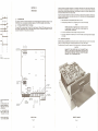
FilJUr.3 ...ows the foctltion of !hi recomrnendtd mounting hoIft.
STEP INSTEPI
'"
""
"
INTERFACE CONNECTIONS
Signlll connection. lor the TM100 '" m-.:M vi" uMr'luppliod 34.pin Il't ribbon connector (3M Part No.
3463-0001 or eqlli""lent). Thil COnnector melll directly with th, PCBA Connector at th, rear 01 the Drive.
The de po....... connector i. , four·pin connector (Amp Metl-N·Lok, p,rt No. 1-480424-0) which miles with
th, COnnector on the logic PCBA It th, top rUr 01 th' Drive. Th, Inttrlec, description 01 !he connectors,
and th, location of
i. conllined in Section III.
WRITE DATA INWRITEDATAI
MOUNTING THE DISK DAIVE
WRITE GATE (NWRITEGATEI
SIDE SELECT INSIOE SELECT)
;===~==
Disio Dn-10- Conl101....
.....
OtocrlPtion {M-..onicl
•
,."
WRITE PROTECT (NWRITEPROTECn
",..
Connector Clamp
ee
M_
~
INOEX IN1NDEXlSECTORI
TRACK
..,..
~
tNTRKflCIl
READ DATA (NREADOATA)
,L;-
,-
--
.... -Irr-'
+
I
TABLE 3
•iEJj
POWER CONNECTOR PIN ASSIGNMENT
"0
,
2
3
•
!)uppiV Voltage
+12\1 de
Return 1+12\1 de)
,
t
,
.
Ie: .. c....
_ _ _ _ u,
'
,,,
I~P
+
Rllu,n j+5v del
'01'" "I "OUNtlNG NOLE$
"" ,,,, u,."', ,."
ON IIN<T '.R"P€ II0Tt""',
"'u"
PI'
101 "'OUNlIN<; ><OLII.
rwo I" ON "'CH so".
,,", .", IINC·:II, " ' "
OUTLINE - TM100 DISK DRIVE
Fig.. 3
"
6
,.,I
---I
_
... '"
I
1.12.1 HARDWARE
The Oi,k O<ive I, "",,,,,,lllClured with ee<gln crllk:tl ,nlernal Illgrvoan,S thai must be "",Inglr-.cl. Th"efore.
" I. imporgnl Ihlll me mounting hlrd_rl does nol Introduce significanl II.... on 1M Orivl.
Anv mounll"'illChlrnl In ..... ic:/'I !hi 0<.... I, pert of 1M stt"Uf;:I"..1 In""grity of 1M 1IrlC1ow.. II not permitted.
a
Mounl''''iI tct>em.. Ihoould Illow for Idjllsubl, brleklll or IncorporaU! rlKilienl I\'lWI'lobtB 10 aQIXlIl1I'rtOdati
tol..-__
Mount''''iI td>tm_ illWlhrl"ll more ttIaI'l !hIM mounting poinlll "'ould be avoic*i.
o
1.12.2 DUST COVER
O;,k Orr.. iI nol pr~ with I dust _ , thl design of .. endOSU<l"'ould incorponll I m .....
to pr_' COl'ltlmi,.,ion from loose il""', e.i-, dulr. linl, ~ cMd, lie.
Si~!hI
1,12.3COOLING
...., disaipllio.. from llirge Dilk DriYII iI normlltv 15 _tlll!51 Btu/Hrl "nder hiWo Iii'll conditions.. When
tIM Drive iI mounled 10 Nt !hi COO'I'lP"I'III'lIll
IIOC_ to !hi Ir.. flow of lir,.-mat COI'W'IC"tlon cooling
,lkIwI """Ilion ..- the ~fied '''''''IN.. 1'
.
WhIn Ihe Orr.. ill mounled in I confinMI l""i'OI'IO'I'Ienl, Ii. flow mUll be provided to ....in!.lin 'Pt'cified lir
~I"r.. In tIM ..;cinitv of !hi motoR. PCBA',.1I'ld disktlte.
a
•
SERVO P.C.B.A.
Fi9- 12
1.12.4 DRIVE SEPARATION
In Iddit'on 10 the eooIing rtQlIlr""enl5 IIPfI:lfltd in P.rlgraph 1.12.3,. minimum stpllratlon of 25,4 mm
!I Inchl b e l _ Dr,,,.. iI recommended. Thll ,. rMjuired 10 Ivoid t1..,,,icel inlerference bllt_n IlMmoton
of 0". Drivelnd !hi mag".,;'; tMad of another Drive, ClOHr mounting is ..llowable if I IIO'o'ndtd shMt 01 sllll
aliiI'I 1,52 mm IO.06O-inchl thick is pl""ed bllwMn unil" Ho_r. lISi of Ihit"MI"'MI mlV inc..... the
cooling requlrern,nll.
1.13
3.3
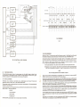
INTERFACE ELECTRONICS SPECIFICATIONS
AU inl.,.f_ si9nt" .rt TTL COnlP8IIb1•. Lovic true (low) I' +a.4v !""'ximuml. logic falll (high. i. +2.4v
(mlnlmuml. Figura 13 Iliultr.tts Ihi inlttfllCe conf1ouration. Ma",mum inl'.-fIlC' cable 1'''lIlh i. 10 f",.
II i, recommlndlld that the Interl,ce cabl, til flit ribbon cable. wim a chlractlri"ic Imped.nce of 100
ohms (or equiVlltnt IwiSlad pairs).
DISKETTE HANDLING AND STORAGE
Intlrface connaclo, pin assignments .nd pow" connaclor pin a"ignmen"are givln in Tabll 2 and Table 3.
II II Important that Ih, di,kttte be handled and stored properlv so Ihat Iha Integrhv of Ihl r..,orded de""
maintained. A da"",ged or cOntaminated dllkeUI can Impair Or pr.... nl recOVIrV of data and can r"lIlt in
damage 10 Ihe , . .dlwri,. head,.
3.3.1 INPUT CONTROL LINES !SMTabll
2.
3.3.1.1 SELECT LINES !NDS1·NDS41
Th, SELECT II"" prowlda. mlanl of HIKllng Ind da..lleling a Disk Dr'v,. Th'M four liOllIND50-NDS3
nandlrdl llllel One 01 Ihe fou, Disk Drivn .tt8d>td 10 11M controUer. When Ihe lignallO\lic 1",,111 i. Uue
Oowl. Ihe Di,k Or,... eltctronic:s.re lC1iVlled and Ihi Drive i. condilioned 10 rtlPOnd 10 SlIP or rlldlwrite
com.... nds. Whtn lhoIlO\Iic level i. ,.1.. (high!. the 'f'4'lt1 conlrol lines .n<! OUlP"'t "tlu' Ii,," We diubled.
A SELECT I,,,. must "main Itlble ,n thl trul IIowl ,tilt unlil the uaetllion of a SlIP or ...elfwrile
cornrntI'ld is ccmpflled.
.."'-DO ....
~_
TIll D;,k Or... eddr... ill detarmlned b'I' • Slltoct Shunt on 1M PCBA. SELECT II,," ().J prooncM I mMns of
dti$v.chtining I mI"io'nu'n 01 four O;,k Oriwo 10 'COl'ltroller. Only ...... Iinol Cln ba """ lIowl"l I .....
An "ndefinMI _"ion "'911 ......11 if two or more unin .e taigned the _
addrlSl or if two or more
SELECT li,,".e in the true Uowl III" simIllta""",",V.
",
_ _ ..,_-.n.'rn
_..,
..-. --.-......
--.....
..... "'"
..
®®
"".. _.NO _.,_
_,0< ""....
._...-_"'
..,... _...
•••,,, ....
...
•
•
--_
...-, .'M .............
....
'-
.... ...
.....
CAll. ..._
_,,'.. """"-0"'
, ,
DISKETTE CARE AND HANDLING
..
. '"
r--------l
'
:,
,,,
,
...."'.0 ••,.
, .........''''_ '-'N'
_ I. "IT
L'~t~_'~_.~~'j
.m,,,••,
INTERFACE CONFIGURATION
Fi9- 4
Fi9- 13
6
"
SECTION III
fllJU" 2 illullr.te. th. phy.iclIl conlilJUratlon of th. di.k.tt•. Th. di.kette I. an oxide coat.-:l, fl.xlbl. myl"
di.k, 130.2 mm 15,125 Inch..l In dl.meter, .nd I•• nclosed In.n 133,4 mm x 133,4 mm (5.25 x 5.2S·;ochl
protactillil jacket. A..dJ.....h.t..._ he.-:lacc... II rn.Idot lh.oogh .n .pertUfe In the jackel. O""nlnGflo. th.
drl.... hub .nd dl.kettl index hole ..e .110 provided,
OPERATION
Figura 4 providellOme helpful hln" on the eK• • nd h.ndlin\l 01 the Di.k Dri"'.nd dloketl'" Addltlomolly,
to .SIU'e troubl .. I1" OPff.lion .nd enhance tile ...-vice 111. of tile dl,ke1t., the 1011owi"ll prac.dur.. lor
kandliO\l shoold be obHn!«l;
J
--.J
If
I
3. 1
INTRODUCTION
This wo;tion COIltlliM 1M interfBl;8 de$<;ription end Ill. metN!nicallclectriQl edjunmentl nceuarv for me
L.-. --.J
1
J
:
,
J
.-
II
,
TM100 Dilk Ori... Allo presented .... IChemItic diagr-8m1 01 th PCBA', ,nnalled in the Oi,k
r
PHYSICAL DESCRIPTION OF THE PCBA',
The logic PCB" i. _oximatlly 146 nvn 15.75 inehal long by 146 mm (5.75 incn..) wi"', and the
_
PCB" •• _ o........ telV 127 mm (5.0 inc:lMJl long by 38 mm 11.6 inchesl w~. Figures 11 end 12
~1
ilIuunlil the
n..
50 oersted I.... of ....,...liring fon:e is rHdIttd ala disunce
of apf1t01tima* 76 tnnl (3 inchesJ from a l'fpa SDU~. e.g.,
",o~ ,-,-alOtl, lralWformerr.
01 lell points end con,*,tol$.
•
•
Do not 110" the d;.katte in diraclsunl"'l as _'pinll could .flUI1•
Do not u. . . IMd pencil or bellpoint pen 10 ..... ite on Ito. Illbel. Use. ,.Iltip pen.nd rll¥k
-'L._"':'"
on
I
1.14
I
~\..._-+-~,
I
.II _ " .
I
s..
~!l ~t
h
1111111111
Et'±"7
~
oC,oq
Ihe magnetic hNd
ecordillll otar8tion, thi,
,;,emlnll establilhed in
lASE lignal 10 allow the
e Read m<><a.
~
OAMAGE TO THE CENTER HOLE IN THE DISKETTE MAY
RESULT IF THE ODOR IS CLOSED WHEN THE DISKETTE IS
NOT PROI'ERL Y INSERTED. THIS WILL PREVENT RELIABLE
RECOVERY OF THE RECORDED DATA
.. o
.~
"jjiii'''''''
"
!n
....
.~
"
head•.
."
-.
..".
- ." ,'
CAUTION
'-.,;.;..,.m;-------------------,
. ,..
--.
•
0000
10<", .,,,
TO""H"'"",
,•
I
i~ I•
.~
.i
Ii
,•;
IV • read .mplifi.... and
filt'r i. pined 10 the
lhe paak. of th, rNd
lOndi"llIO Nell pelk of
'1~lly
LOADING THE OISKETTE
The disklne Ihould be Clrl'fully 1.-1.-:1 unl;1 me ";okllll jackel is solidly .10$' .he b1ckllop.
o " "
~
_1._"",,-
ro~
m.label.
Diskette !oedl..... it fCICO"'IPIilhad by iN«1i"ll m. prqMt1y or"nr.d diskette into the front slOI providMl.
Ac:c- 10 the diIIe"te Iaedi"ll 1101 it gt,ui",.r by openl..... the froot I"ch.
Figu•• 5.
.!'
I
I
Ute.
NOTE
3.2
,~
II--+-
Return the dille.tte 10 the p.olactillil jacket """"'n not In
Avoid ",posiO\lthe dlokel1. to 'OY m'fIII'lizln\llorce In excess of 50 oerl1.-:1.
Dt~.
LOGIC p.e.S.A.
DISKETTE ACCESS
Fi,l. It
Fig. 5
, vi, the READ DATA
,
/
--
•••
~.
t'\J.......... ,tOG
.....""'O,.CT
I
_..
I
M
--
........ ..,.
I
_"f
_'IC'
.'~
_.
M~
f~·~
9,
, ,
II ,l.
~<I:.
I
I
C,C JT ......
rooo","
o
e,T
-_. .....
I~c_,,,,....,
I
~-
-
"""""."ZAllON
•
n
o
•
'
•
I
,
I
M
I
:
I
I
I'
;
,,
,0
,,
:
1
:
"
~
I~
J~U:UI~U
I
,
I
,
I
I
'
:
:
f
I
I
I
n
I,
'
I
I
~
l'l",~
"
I
'''''--'-''
_mc:U"'<HTS~
Iii
:
I
I
I
I
•••
C<0
0
0
0
0
0
I
I~-
-~
0
0
"-"-""
--- -- _..-..
...........
. ---
-~
'ATTORN
nw'''ToOATA
r
I
,
-H "T cn~
I
I
I
I
I
:
:
I
,
I
,
1
'i€hi'
i, :1 ;, ,j :, :I
H
:
I
I
,
,
,
,
I
HH'S
:I
I
:,
I
F M RECORDING
Fie- B
I~
~
I - -•.."..
.,. ........
_
....a
....... -........
-",,"""'"
2.10.1 OATA RECORDING
R.,...,.ing to F..... 7. il an be __ lhel the Write Electronice COfIIisl 01 • Write/Er_ Currenl Source Ind
Write W~orm G""""IOr. Erase Current Source. Trim Ere. Control Logio::. Ind Hlllld Select l.ogic.
The ..-dI_ite winding on the megnetic I - ' iI cerl1er-tepped. During. _ite opention, currenl from the
Writ. Current Source Ilow in .llernate hal.... of the winding under control of the Write W.......orm Ge"""lor.
TM 100 FUNCTIONAL BLOCK DIAGRAM
Belor. r.cordlng con begin. certain condilions must be Alisfied. The condilions required for rllCOrding
Fig. 7
Ii.•.. unit reedy) must be IIStebI""ed by the u_ system lIS followl:
111 Drive 1Pftd sUlbilizalion. Thi. condition will 'Hilt 250 msec Ifter ...ting the drive mOlor.
121 Subsequenl 10 any Slep operation, Ih. potitionar mUll be .lIowed 10 501111. ThiJ rllq"ir.. 20 msec
lotel 1ft... the l8It step pul... it inil;"led, l.•. , 5 mHC for the ttep motion.nd 15 msec lor :JetIling.
NOTE
All of ,he fongoing "".".iolll C... be
POSITIONER CONTROL
Thl Hud PO$ltioning tVlt... utlliz,•• fou.-pl\a,.. lteppif mOtor df'" ... ic:h ella",," 0.... ph_ '04" Meh
track 1dvan«m>lf'll 0/ me RtodlWrill CIIrr• . In addition to the logic necessary lor motion ""ntrol, tlll''- II
prov;dld I' an .Iemlnl for InhibitIng polltloner mOlion during. _itl operation.
2.10
DATA El.ECTRONICS
Information ca n l» '«o.dk! On tl>, diskettl ".ing a doubl.freq"lncy oodl. Flour. 8 iIIUltTltft the
magn.tization profilM in _II bit C1111 lor lh, numbe<' S<t<luence shown.
The .ra. ll"PI p.ovid, an erased l/UI,d beoo On ,Ith".,. side of the ,,,,,arded track. Thi. IICcommodn.. lila
lolerlnell in 1.1>1;. POIilionlng.
Alilignall requiorld 10 <0111'0111>, da'- e4ectronICl.re provided by the user Jy".......nd ere Jhown in th. block
diagrem, Figure' 7, Th.H control JigNlIJ ere:
... SELECT
",",I~d,
if required.
Figure 9 shOWl lIN! .allMlnlliming diagram for. _Ite operlt'on, AI t· 0 when Ihl "nil It readY, Iha WRITE
ENABLE int..tee.line IlD'" lr"a, thiJ enabl.. Ih. Write Curr.nl Source.
J.
Sine. th. trim era... gaps erl behind Ih. read/_ite gep, lhe TRIM ERASE control goes trua 390 uMc aft...
thi WRITE ENABLE Intedace Ii ..... It should be nOled thet thlJ velue Is optimized belWtltn the requirements
al Track ee Ind Treek 34 SO lhallhe Iff""t of tM trim araH gapt on pr....IOIlJ in/ormalion IJ minimized.
Flgur. 9 shOWJ th. informalion on Ih. WRITE DATA inl.rfee. 1101, end the output 0/ 1M Wri~a W..../orm
Generalor which 100000Iet on the leading adge of avery WRITE DATA PUIH.
Note Ihat a minimum 0/ 4 UJeC and a muimum of 8 uJIC betwean WRITE ENABLE going true and Iha flrsl
WRITE DATA pulMl is only required If /aith/ul reproduction of thallm WRITE DATA I.. n,ilion I' Jlgnlficant
AI the .nd of rflCOrding, at least on.. addillonal PUIH on the WRITE DATA Ii", m"n be inserled IInr the
Iltl Jlgn;/le.tInl WRITE DATA pulMllo evold INCflJlve peak p,ift atflJClJ.
Th. TRIM ERASE signal musl remBin tr"a lor 800 uJIC Ifter Ih" larmiNllion of WRITE ENABLE 10 amu ..
trn.t III racorded dall a .. Irlm arued. This \IlIlua is 1ge1n oplimized bat_n the rllquirem.nlJ et Tracks fie
and 34.
... WRITE ENABLE
... WRITE DATA
... SIDE SELECT
The READ DAliA compotite Jlgnal is "",I to Ih.....r IVstem v;" the inlerface.
"
Tha durBlion of a wrll' oparetion i, from thl lrua"9Ding edge 0/ WRITE ENABLE 10 lhe fBlsa-gOing edge 0/
TRIM ERASE. ThIJ illndlcaled by thl int......1WRITE BUSY "",va/orm shown.
"


![10780-90006 - 10780A Laser Receiver for 5501A [Prefix 1948] (Mar](http://vs1.manualzilla.com/store/data/006009643_1-6e2f54ebb2199ef6df634558ba4c1bb6-150x150.png)