1
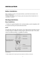
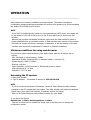
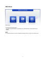
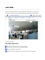
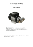
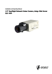
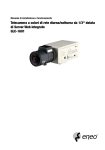
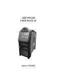
NXD-1602M
Full HD NETWORK CAMERA
GB
Please read this manual thoroughly before use and keep it handy for future reference.
DESCRIPTION
--------------------------------------------------------------------------------------------------------------------------The NXD-1602M vandal resistant dome is an internet protocol based megapixel network
camera with a built-in web based viewer accessible by multiple browsers. The camera has a
connection feature for third-party applications. It is supplied with Zelaris Elements utility
software to search, configure, manage, live view, record and playback.
The camera supports dual compression formats and multiple streaming simultaneously. The
two standard compression formats include H.264 and MJPEG. The multiple streams can be
configured to a variety of resolutions, bit rates and frame rates.
The camera uses 1/2.8 inch CMOS sensor and Focal length 3~9mm lens and also supports
PoE (Power over Ethernet), DC12V, and AC24V.
Model
NXD-1602M
Full HD, Day and Night, WDR, Vandal resistant dome
Components
Quantity
Description
2
Camera
2
Installation CD
1
Accessory kit for installing Dome Camera
1
Template sheet
1
Extension connector kit
NOTE
Adapter for DC12V / AC24V are not supplied.
2
Camera Layout
Top View
Lens: 3-9mm vary-focal megapixel lens
Connection Cable: 26pin camera extension cable
Connection Cable
Main POWER connection
- RED; DC12V or AC24V
- WHITE; GND or AC24V
Heater POWER connection (Optional)
- ORANGE; DC12V or AC24V
- BLACK; GND or AC24V
3
ALARM connection
-
PINK; Alarm Input 1
GREEN; GND
YELLOW; Alarm Input 2
BROWN; GND
Light BLUE; Alarm Out
GRAY; GND
RJ-45 connection: Connect Ethernet cable or supplies power to the camera if PoE is
available.
BNC connection: Connect BNC cable for composite video output.
SPEAKER connection (GRAY): Connect external speaker for audio output.
MIC connection (BLACK): Supplies external microphone as an audio input source.
4
INSTALLATION
---------------------------------------------------------------------------------------------------------------------------
Before Installation
Before installing the camera, thoroughly familiarize yourself with the information in this
section of the manual.
To ensure secure access to the IP camera, place the camera behind a firewall when it is
connected to a network.
Starting Installation
Base Installation
1. Position the supplied template in the mounting location, use this template to drill
the required mounting holes and cable access holes
NOTE
The total mass of the main unit is approx 1.3kg. Check whether the ceiling to which
the Dome Camera is installed is strong enough to hold the unit mass. If not, either
mount ifn a different position or strengthen the ceiling.
[Lock Screw]
2. Attach safety wire for securing the dome camera to ceiling or structure.
5
3. Insert each cable through the cable hole, connect BNC cable and communication lines.
4. Unlock (4x) torx screws on the dome cover and fix the dome case firmly with supplied
mounting screws (4x), plastic anchors (4x), O-Rings (4x).
5. Adjust desired focus and scene by turning and moving the hemisphere by hand.
6. Replace the housing cover and secure with the torx screws (4x).
Heater Kit Installation (Optional)
1. Place the heater element is slot “A”. Please ensure that the cables are facing upwards and
the heater is pointing towards the Dome.
2. Place the PCB in slot “B”. Please ensure that the PCB is facing inward with the connection
blocks at the top.
3. Place the plug in the Socket “C” (J3) which is found on the controller board.
[Heater Kit Installation]
NOTE
- Heater power consumption
Power Supply
AC24V
DC12V
Power Consumption
20Watt
10Watt
Heater On
at 41°F (5°C)
Heater Off
at 59°F (15°C)
[Heater Power Consumption]
Power
Use Certified/Listed Class 2 power source only.
-
Connection to an IP network
IP Assignment
See Page 7.
6
OPERATION
--------------------------------------------------------------------------------------------------------------------------Before starting the camera, installation must be complete. The camera completes a
configuration sequence taking approximately 40 seconds from powering up. Once completed
the amber LED will flash once a second.
NOTE
- If the DHCP is enabled but the camera is not connected to a DHCP server, the camera will
be set default IP 192.168.30.220 and try to get IP from DHCP server about every two
seconds.
- Network and processor bandwidth limitations might cause the video stream to pause or
appear pixelated when an increased number of Web-interface users connect to the camera.
Decrease the images per second, resolution, compression, or bit rate settings of the Webinterface video streams to compensate for network or processor limitations.
Minimum conditions for using web browser
The minimum system requirements to use a Web browser with this IP camera are as
follows:
- CPU: Pentium® 4 microprocessor, 2.0GHz
- Operational System: Windows XP® or Windows Vista® or Windows7®
- System Memory: RAM 512 Mbyte
- Ethernet: 100 Mbit
- Video Resolution: 1024(Horizontal) x 768(Vertical) pixels or higher
- Internet Explorer® 7 or later
- ActiveX® 1.0.0.13 or later
Accessing the IP camera
1. Open Web browser
2. Type IP address: - The default IP address is 192.168.30.220
NOTE
- If you do not know the camera’s IP address, install the Zelaris Elements utility software
available on the CD supplied with the product. The utility software will locate the assigned
Model name, Host name, MAC address, IP address, Version and others.
- Refer to the Zelaris Elements utility software manual for more detail.
3. Log On to the camera
Default User = admin, default password = admin
- Click the Live View icon for default live image view or the Setup icon to change the
configuration values.
7
Main Menu
[Main Menu]
The dialog box will be appears.
- Type User ID and Password in the dialog box. The default User ID and Password are
admin.
NOTE
For security purposes, be sure to change the password after you log on for the first time.
8
LIVE VIEW
------------------------------------------------------------------------------------------------------------------------The Live View page provides you to select the properties of video source. You can view the
live image from this page and also access the Setup menu and operate the main functions.
[Main Live View Page]
Live Video Page Icons
Hide Main Icons: Hides main icons in the live view page.
Show Main Icons: Shows main icons in the live view page.
Live view: Displays live video stream.
Playback View: Enters playback menu. Required Micro SD card (not supplied)
9
Setup: Enters setup menu.
Help: Shows helpful information.
Source: Specify the viewable video stream source to display in live view page.
View Size: Specify the viewable video size to display in live view page.
Stream Type: Specify the internet protocol to display in live view page.
ROI View: Specify the specially selected area to transfer using different stream feature
in the primary video image. ROI is an abbreviation for “Region of Interest”.
Preset: Specify the Preset. This icon is inactivated if the PTZ settings are not set.
Pause: Pause the live video stream.
Snapshot: Take a picture of the video image currently on display. Supports the origin
image size view, Print, and Save feature.
Digital Zoom: Supports a digital zoom in live video image.
Full Screen: Expands video image to the entire screen area.
Manual Trigger: Activates the Alarm Out signalling manually.
Speaker: Adjusts the volume of Speaker and switch the sound on / off.
Microphone: Adjusts the volume of Microphone and switch the sound on / off.
10
Troubleshooting
---------------------------------------------------------------------------------------------------------------If you suspect a problem is being caused by incorrect configuration or some other minor
problem, consult the troubleshooting guide below.
Upgrading the Firmware
Firmware is software that determines the functionality of the network camera. One of your
first actions when troubleshooting a problem should be to check the current firmware. The
latest version may contain a correction that fixes your particular problem. The current
firmware version in your camera is displayed on the Basic Configuration or About menus
screens. For the latest firmware of the camera, please contact your supplier.
Detailed instructions on how to perform the upgrade process are provided with each new
release. See also the Maintenance/ Upgrade for more information.
General Troubleshooting
The following list covers some of the problems that may be encountered and suggests how
to remedy them:
Symptom → possible causes and corrective actions
1. The camera cannot be accessed by some clients.
→ If using a proxy server, try disabling the proxy setting in your browser. Check all cabling
and connectors.
2. The camera works locally, but not externally.
→ Check if there are firewall settings that need to be adjusted. Check if there are router
settings that need to be configured.
3. Poor or intermittent network connection.
→ If using a network switch, check that the port on that device uses the same setting for
the network connection type (speed/duplex).
4. The camera cannot be accessed via a host name.
→ Check that the host name and DNS server settings are correct.
5. Not possible to log in.
→ When HTTPS is enabled, ensure that the correct protocol (HTTP or HTTPS) is used. When
attempting to log in, you may need to manually type in http or https in the browser's
address bar.
6. No image using Refresh and/or slow updating of images.
→ If images are very complex, try limiting the number of clients accessing the camera.
7. Images only shown in black & white.
11
→ Check the Video & Image setting.
8. Blurred images.
→ Refocus the camera.
9. Poor image quality.
→ Increased lighting can often improve image quality. Check that there is sufficient lighting
at the monitored location. Check all image and lighting settings.
10. Rolling dark bands or flickering in image.
→ Try adjusting the Exposure Control setting under AE and AWB part.
11. H.264 not displayed in the client.
→ Check that the correct network interface is selected in the Video & Image/Stream.
12. Multicast H.264 not displayed in the client.
→ Check with your network administrator that the multicast addresses used by the camera
are valid for your network. Check that the Enable multicast checkbox are enabled in the
System/Network/RTP tab. Checks with your network administrator to see if there is a
firewall preventing viewing.
13. Multicast H.264 only accessible by local clients.
→ Check if your router supports multicasting, or if the router settings between the client
and the server need to be configured. The TTL value may need to be increased.
14. Colour saturation is different in H.264 and Motion JPEG.
→ Modify the settings for your graphics adapter. Please see the adapter's documentation for
more information.
15. Poor audio quality.
→ Too many users/clients connected to the camera may affect the sound quality adversely.
Try limiting the number of clients allowed to connect.
16. Distorted audio.
→ Check that the correct Audio Input source is selected. Select Microphone for a connected
external microphone. Select Line for a connected line in source.
NOTE
If you cannot find the help you require, please see the User's Manual, or contact with your
network administrator.
12
memo
eneo® is a registered trademark of Videor E. Hartig GmbH
Exclusive distribution through specialised trade channels only.
Videor E. Hartig GmbH
Carl-Zeiss-Straße 8 • 63322 Rödermark, Germany
Tel. +49 (0) 6074 / 888-0 • Fax +49 (0) 6074 / 888-100
www.videor.com
www.eneo-security.com
Technical changes reserved.
© Copyright by Videor E. Hartig GmbH 07/2012