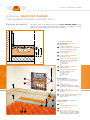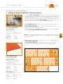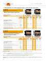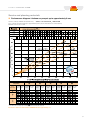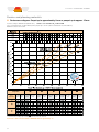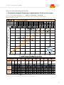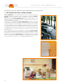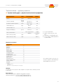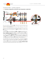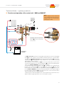
1
Ceramic thermal comfort floor Schlüter ®-BEKOTEC-THERM Technical Manual 01 - 2012 www.bekotec-therm.co.uk S c h l ü t e r ®- B E K O T E C - T H E R M Werner Schlüter SCHLÜTER-SYSTEMS KG S c h l ü t e r ®- B E K O T E C - T H E R M About this manual: The design principle of the ceramic thermal comfort floor The innovative Schlüter®-BEKOTEC-THERM heating system is referred to as a “ceramic thermal comfort floor” to emphasise the fact that our company views the heating system of the floor as a system assembly, in which all components, design planning and construction must seamlessly fit together. After all, to meet the many requirements, the “ceramic thermal comfort floor” must provide insulation, heating, cooling and waterproofing in wet areas, while also absorbing traffic loads and serving as a visually appealing design element. The experience of the past has shown how difficult it is to achieve a satisfactory balance between the aspects of construction, physics and heating technology in the overall floor assembly. As a consequence, conventional heated screeds with ceramic and natural stone coverings frequently buckle and form cracks. This is mainly attributable to the fact that screed, ceramics and natural stone expand and contract at different rates due to their different heat expansion coefficients during temperature changes. The provisions of the corresponding standards, for example the regulations that specify the thickness of the screed, the position and type of movement joints, the construction of reinforcement inserts, or the maximum residual moisture for tile installation, have frequently turned out to be insufficient in physical terms. From the perspective of heating technology, the disadvantage of a relatively large mass of screed is that a great amount of heating energy must initially be used and stored. Conventional radiant heated floor systems therefore are slow to respond to temperature changes. Our complete system, Schlüter®-BEKOTEC-THERM, is a construction that solves all these problems in one internationally patented assembly. In this regard, the name “BEKOTEC“ stands for the technique of the assembly construction and “THERM“ for the heating components. Schlüter®-BEKOTEC-THERM is based on a thin layer floor assembly of cement or gypsum based screeds which are applied on top of the studded Schlüter®-BEKOTEC panels, where stresses in the screed are reduced due to the stud pattern of the panel. With the help of Schlüter®-DITRA 25, ceramic tiles can be installed as soon as the cement screed is ready to bear weight. Our THERM components series is a heating technology that is an exact match for Schlüter®-BEKOTEC and includes everything from heating pipes to electronic control systems. The relatively small amount of screed and the proximity of the heating pipes to the surface allow for a quick reaction to temperature changes. Thanks to the interconnected air channels in the Schlüter®-DITRA 25 matting, the heat is distributed evenly. This makes Schlüter®-BEKOTECTHERM a quick reacting “ceramic thermal comfort floor“ that can be operated with great energy efficiency at very low supply temperatures. Of course, any other flooring materials can be installed over the Schlüter®-BEKOTEC screed as well. Schlüter®-BEKOTEC-THERM, which is equally suited for new constructions and the refurbishment of older buildings, offers developers many advantages and true “added value.“ Since the applicable standards, regulations and even legislation tend to make construction work more complicated instead of easier, this manual was written to document the construction steps of installing a Schlüter®-BEKOTEC-THERM ceramic thermal comfort floor in a simple and understandable way. Sincerely, Schlüter-Systems KG 3 S c h l ü t e r ®- B E K O T E C - T H E R M S c h l üt e r ® -B E KOTE C-T H ERM T h e ce r amic t he rma l c om f o rt f lo o r System assembly This picture shows the assembly structure of the Schlüter®-BEKOTEC-THERM ceramic thermal comfort floor with the associated system components. The numbers in the image represent the corresponding products of the system assembly. Schlüter®-BEKOTEC-THERM System components of the modular heated floor assembly. 1 Schlüter®-BEKOTEC-EN tudded screed panel for the attachment S of Schlüter heating pipes ø 16 mm. 2 Schlüter®-BEKOTEC-BRS Screed edge strip. 3 Schlüter®-BEKOTEC-THERM-HR Heating pipe ø 16 mm. 4 Schlüter®-BEKOTEC-THERM-HV Stainless steel heating circuit distributor with connection accessories a hot flow leg b cold return leg. 5 Schlüter®-BEKOTEC-THERM-VS Distributing cabinet. 6 Schlüter®-BEKOTEC-THERM-E Electronic temperature control a interior thermostat b actuator c control module. * mm a 5 4 System components for the installation of tile and natural stone (see separate price list and product data sheets). c 6 a b b 9 8 12 2 7 3 4 1 11 10 7 Schlüter®-DITRA 25 ncoupling, heat distribution, bonded U waterproofing, vapour pressure equalisation. 8 Schlüter®-DILEX Maintenance free edge and movement joint profiles. 9 Schlüter®-RONDEC or Schlüter®-QUADEC Decorative finishing profiles for walls, skirting and floors. System components not available from Schlüter-Systems. 10 Screed Cement or gypsum based screed. 11 Thin-bed tile adhesive 12 Ceramic tiles or natural stone Other coverings such as carpet, laminates and parquet are also feasible in compliance with the applicable installation standards. S c h l ü t e r ®- B E K O T E C - T H E R M Contents Page Contents Page Ceramic thermal comfort floor – application and properties Installation notes and system start up for various floor L Application areas / traffic loads . . . . . . . . . . . . . . . . . . . . . . . . . . . . . 6–7 coverings L Thermal properties . . . . . . . . . . . . . . . . . . . . . . . . . . . . . . . . . . . . . . 8–9 L Ceramic and natural stone coverings . . . . . . . . . . . . . . . . . . . . . . . . . . 68 L Regenerative sources of energy and modern heating technologies . . . . . 10–11 L Non ceramic coverings . . . . . . . . . . . . . . . . . . . . . . . . . . . . . . . . . 68–69 L Advantages for users . . . . . . . . . . . . . . . . . . . . . . . . . . . . . . . . . . . . . . 12 L Heating / curing . . . . . . . . . . . . . . . . . . . . . . . . . . . . . . . . . . . . . . . . . . 70 L Residual screed moisture . . . . . . . . . . . . . . . . . . . . . . . . . . . . . . . . . . 70 Prerequisites and implementation L Installation notes, general requirements and construction prerequisites, preparing the substrate . . . . . . . . . . . . . . . . . . . . . . 13–14 Innovative system solutions L Application and scope . . . . . . . . . . . . . . . . . . . . . . . . . . . . . . . . . . . . . 71 L Structural and/or movement joints in the load bearing substrate . . . . . . . 14 L Requirements for additional thermal and sound insulation and separating layers . . . . . . . . . . . . . . . . . . . . . . . . . . . . . . . . . . . . . 15 L Edge strips and edge joints . . . . . . . . . . . . . . . . . . . . . . . . . . . . . . . . . 16 Assemblies with Schlüter®-BEKOTEC-EN 23 F (Low construction height) L Installing the Schlüter®-BEKOTEC studded screed panel . . . . . . . . . . . 17 L Installing the Schlüter®-BEKOTEC-HR heating pipes . . . . . . . . . . . . . . 18 System assembly L Prerequisites for installing conventional cement or gypsum L Of the ceramic thermal comfort floor . . . . . . . . . . . . . . . . . . . . . . . . . . 35 based screeds . . . . . . . . . . . . . . . . . . . . . . . . . . . . . . . . . . . . . . . . . . . 19 L Joints in the Schlüter®-BEKOTEC system . . . . . . . . . . . . . . . . . . . . . . 19 Application and function L Non buckling, thin layer covering assembly . . . . . . . . . . . . . . . . . . . . . 36 Additional system products for ceramic tiles and natural stone Prerequisites and installation L Installing the Schlüter®-DITRA 25 uncoupling mat . . . . . . . . . . . . . . . . 20 L Installing the studded screed panel L Installing joints in the surface with Schlüter®-DILEX . . . . . . . . . . . . . . . 20 Schlüter®-BEKOTEC-EN 23 F . . . . . . . . . . . . . . . . . . . . . . . . . . . . . . . 37 L Additional products for wetrooms and barrier free bathrooms . . . . . . . . 20 Schlüter®-BEKOTEC-EN 23 F Service and planning materials L Advantages . . . . . . . . . . . . . . . . . . . . . . . . . . . . . . . . . . . . . . . . . . . . . 38 L Our service . . . . . . . . . . . . . . . . . . . . . . . . . . . . . . . . . . . . . . . . . . . . . 21 L Thermal insulation of floor heating system according to EnEV and DIN EN 1264-4 . . . . . . . . . . . . . . . . . . . . . . . . . . . . . . . . . . . . 22–23 L Floor assemblies for various application areas – ceramic Installation overview (with page references) L 8 step installation guide . . . . . . . . . . . . . . . . . . . . . . . . . . . . . . . . . 72–73 thermal comfort floor . . . . . . . . . . . . . . . . . . . . . . . . . . . . . . . . . . . 24–27 L Impact sound measurements . . . . . . . . . . . . . . . . . . . . . . . . . . . . . . . 28 L System data and example: Appendices Ceramic thermal comfort floor Schlüter®-BEKOTEC-THERM . . . . . . 29–30 I.I Project engineering data sheets . . . . . . . . . . . . . . . . . . . . . . . . . . . 74–75 L System data: with non ceramic floor coverings . . . . . . . . . . . . . . . 31–33 I.II Project description . . . . . . . . . . . . . . . . . . . . . . . . . . . . . . . . . . . . . . . . 76 L Certified quality . . . . . . . . . . . . . . . . . . . . . . . . . . . . . . . . . . . . . . . . . . 34 I.III Window specifications . . . . . . . . . . . . . . . . . . . . . . . . . . . . . . . . . . . . . 77 II Filling, flushing and venting . . . . . . . . . . . . . . . . . . . . . . . . . . . . . . . . . 78 Technical data – system products III Pressure sample report . . . . . . . . . . . . . . . . . . . . . . . . . . . . . . . . . . . . 79 L Schlüter®-BEKOTEC-THERM-HR system heating pipes . . . . . . . . 39–41 IV Heating pipe pressure loss diagram . . . . . . . . . . . . . . . . . . . . . . . . . . . 80 L Room temperature thermostat technology . . . . . . . . . . . . . . . . . . . 42–43 V Distributor pressure loss diagrams . . . . . . . . . . . . . . . . . . . . . . . . . . . 81 L Heating circuit distributors . . . . . . . . . . . . . . . . . . . . . . . . . . . . . . . . . 44 VI Heating up and cure heating screeds with non ceramic coverings . . . . . . . 82 L Distributor cabinet for concealed installation or wall mounting . . . . 45–46 VII Certificate for CM measurements of non ceramic coverings . . . . . . . . 83 L Connection sets for calorimeters . . . . . . . . . . . . . . . . . . . . . . . . . . . . . 47 L Water temperature control unit for supply temperature, use, function and installation with sample design plan. . . . . . . . . . . . . . . . . 48–53 L Mixing stations BMS or BMS/RT, Use, function and installation with sample design plan . . . . . . . . . . . 54-62 Floor heating for individual heating circuits L Return temperature limit valve, function, installation Set up and start up . . . . . . . . . . . . . . . . . . . . . . . . . . . . . . . . . . . . 63–67 5 S c h l ü t e r ®- B E K O T E C - T H E R M Ceramic thermal comfort floor – application and properties Application areas The ceramic thermal comfort floor Schlüter®-BEKOTEC-THERM is an easily assembled, safe system with low construction height and short installation times for new buildings, renovation projects, exhibition halls, bathrooms and swimming pools. As a consequence, the application areas of the ceramic thermal comfort floor Schlüter®BEKOTEC-THERM are especially versatile. The construction advantages and thermal technology benefits of the system can be used in customised applications in the following areas. New construction The quick installation of the entire ceramic thermal comfort floor system saves time and cost. This is made possible by installing the uncoupling membrane Schlüter®-DITRA 25 in conjunction with ceramic tile or natural stone coverings as soon as the screed is ready to bear weight. The system does not require any functional heating or curing after interface assembly, as is customary with conventional heated floor constructions. Due to the low screed mass, the ceramic thermal comfort floor has heating and cooling properties that respond quickly to thermostat adjustments. The effective heating performance and low supply temperature of the ceramic thermal comfort floor in addition to conventional heating systems allows for the use of modern heating technology and regenerative energies, such as heat pumps and solar heating systems. The ceramic thermal comfort floor even allows for passive cooling in the summer. The low construction height of Schlüter®-BEKOTEC-THERM allows for compliance with low construction height specifications. This means: • Spare space for installing insulation materials to comply with mandated insulation values, or • Improved insulation values by installing additional insulation materials. Renovations Conventional floor heating systems with screed coverings of at least 45 mm over the heating pipes can weigh 130 kg/m2 or more. Because of the significantly lower construction height and lower screed mass in the Schlüter®-BEKOTEC system, the weight of 1 m2 screed is just 57 kg, with a minimum cover of 8 mm (over the studs). Due to the savings in screed mass, much less moisture (mixing water) is brought into the construction assembly. For renovation projects, the following are essential: low weight (static concerns) and low construction height. For this reason, the installation of the Schlüter®-BEKOTEC-THERM ceramic thermal comfort floor is feasible even when a conventional heated floor system has to be ruled out. Even lower assembly heights (minimum of 31 mm to the top edge of the screed) can be achieved with the studded screed panel Schlüter®-BEKOTEC-EN 23 F (see Page 35). Sales areas and car showrooms The load bearing capacities of the thin Schlüter®-BEKOTEC-THERM ceramic thermal comfort floor has proven its lasting value in many large scale projects. The regular patterns of the Schlüter®-BEKOTEC studded panel evenly reduce tensions in the screed, which allows for constructing the screed without joints. The free arrangement of movement joints in the joint pattern of the ceramic covering, therefore, allows for a great variety of design options. Wet areas The waterproofing membranes Schlüter®-DITRA 25 and Schlüter®-KERDI are certified bonded waterproofing assemblies for wet areas of classes 0 – B0 in accordance with the ZDB information and for the load classes A1, A2 and C in areas requiring German construction permits. Consequently, these systems are particularly suitable for use in bathrooms, swimming pools and other areas with high moisture loads. The system is also ideal for the safe and quick installation of barrier free bathrooms with level shower cubicles. 6 S c h l ü t e r ®- B E K O T E C - T H E R M Ceramic thermal comfort floor – application and properties Traffic loads Schlüter®-BEKOTEC-THERM Application areas with screed covering, depending on traffic loads and surface coverings Floor covering Maximum traffic load according to DIN 1055 Ceramic tile/ natural stone 5.0 kN/m2 8 mm PVC, linoleum, carpet, cork 2.0 kN/m2 15 mm Residential and offices 5.0 kN/m2 15 mm Residential, offices, medical offices, classrooms, exhibition halls, car dealerships, warehouses 5.0 kN/m2 8 mm Residential, offices, medical offices, classrooms, exhibition halls, car dealerships, warehouses 2.0 kN/m2 8 mm Residential and offices Parquet without tongue and groove connection Parquet with tongue and groove connection Floating parquet, laminate Minimum system coverage with conventional screeds* Areas of application Residential, offices, medical offices, classrooms, exhibition halls, car dealerships, warehouses, workshops with low intensity traffic *For height adjustment purposes and levelling, the thickness of the screed may be increased to a maximum of 25 mm over some of the studs. However, the overall height of the screed over the studs should be within 8 –15 mm. Note: The uncoupling mat Schlüter®-DITRA 25 must be used for the installation of ceramic tile and natural stone coverings. The height of the mat assembly (approximately 5 mm) is to be included in the assembly calculations. All other covering materials listed in the table are directly installed over the Schlüter®-BEKOTEC screed without the Schlüter®-DITRA 25 uncoupling mat. Keep in mind the installation height and final height of Schlüter®-DITRA 25 when calculating the height of the screed with regard to adjoining areas with tile coverings. For this reason, the table indicates a screed coverage of 15 mm for thin floor coverings such as PVC, linoleum, or carpet. In addition to the applicable installation guidelines, note the permissible residual moisture level of the screed for the selected covering material. For further information, please see page 13, 20 and 68. Please don‘t hesitate to contact our technical department with any questions you may have. Screeds to be used: CT-C25-F4 (ZE 20) or CA-C25-F4 (AE 20). The flexural strength of the screed may not exceed F5. 7 S c h l ü t e r ®- B E K O T E C - T H E R M Ceramic thermal comfort floor – application and properties Thermal properties The construction advantages and the cooling and heating benefits of Schlüter®-BEKOTECTHERM are most pronounced in conjunction with ceramic tile and natural stone coverings. The average heating water temperature for the ceramic thermal comfort floor is 30 °C in most buildings with sufficient insulation. In addition to conventional heating systems, the ceramic thermal comfort floor can be effectively operated with state of the art heating technology such as condensing boilers and regenerative sources of energy, e.g. heat pumps and solar systems. The performance comparison shown below clearly highlights the thermal advantages of the ceramic thermal comfort floor. Practical performance comparison of ceramic coverings and thick carpeting / parquet Ceramic thermal comfort floor Thick carpet / parquet (Rλmax= 0.15 m * K/W) ϑm ≈ Average heating water temperature – Room temperature in this example: ϑm ≈ 30 °C – 20 °C = 10 °C Determination of the average excess heating temperature: Limit curve 15 K (Peripheral zone) Limit curve 9 K (Living zone) Excess heating temperature ϑm Excess heating temperature ϑm Determination of the average excess heating temperature: Heat flow density q in W/m2 (heat output) Limit curve 15 K (Peripheral zone) ϑm ≈ Average heating water temperature – Room temperature in this example: ϑm ≈ 30 °C – 20 °C = 10 °C Limit curve 9 K (Living zone) Heat flow density q in W/m2 (heat output) The exact output data from the thermal review of the system are shown on pages 29 to 33. Summary Ceramic thermal comfort floor Schlüter®-BEKOTEC-THERM This sample calculation shows that carpet and hardwood floors reduce the heating performance by 47% compared to a ceramic thermal comfort floor because of their unfavourable thermal resistance factors. A heat output of 56 W/m2 was assumed for a room temperature of 20 °C. The heating pipe installation distance VA was 150 mm. Moving vertically up to the intersection of the output line of the installation distance VA 150 with the desired output of 56 W/m2, the left scale shows the corresponding excess heating temperature for the ceramic thermal comfort floor as 10 °C. This excess heating temperature means that the heating water on average has to be 10 °C warmer than the desired room temperature to stay at the output level of 56 W/m2. The average heating water temperature is calculated as follows: 10 °C excess heating temperature (ϑ m) + 20 °C room temperature = 30 °C average heating water temperature. Schlüter®-BEKOTEC-THERM and carpet (Rλmax=0.15 m2 K/W) Under the same conditions, a heating water temperature of 38.5 °C is required for an output of 56 W/m2 when carpet is used with a thermal resistance of Rλmax =0.15m2. This is the equivalent of an excess heating temperature of about 18.5 °C in the diagram. If the average heating water temperature is left at 30 °C, the heat output falls to 29 W/m2. 8 S c h l ü t e r ®- B E K O T E C - T H E R M Ceramic thermal comfort floor – application and properties Thermal properties Heat distribution function The fast heating of the system with low screed coverage highlights the excellent thermal conductivity of ceramic coverings. This was documented by a thermal technology test of the independent Laboratory for Process Technology at Darmstadt University. The heat radiation and convection processes in the interconnected air channels of Schlüter®-DITRA 25 provide additional heat distribution and ensure an even surface temperature. The low screed coverage achieves maximum heating performance with low supply temperatures (see also performance diagrams on pages 29 to 33). Thermographic analysis of heating response and heat distribution 1Start of heating phase with a surface temperature of 16 °C. The picture was taken after 10 minutes of system operation. Average surface temperature above the heating pipe: 18.5 °C. 2 The picture was taken after 20 minutes of system operation. Average surface temperature above the heating pipe: 19.5 °C. The heat distribution within the uncoupling mat Schlüter®-DITRA 25 shows first temperature increases between the heating pipes. 3 The picture was taken after 30 minutes of system operation. Average surface temperature above the heating pipe: 21 °C. The heat distribution within the uncoupling mat Schlüter®-DITRA 25 shows a clear temperature increase between the heating pipes. 4 The picture was taken after 40 minutes of system operation. Average surface temperature above the heating pipe: 22.5 °C. The heat distribution within the uncoupling mat Schlüter®-DITRA 25 provides an even surface temperature and low heat fluctuations. Summary • • • • Very little temperature fluctuation between the heating pipes. Quick combination of surface temperatures between the heating pipes. The requirements of the Energy Savings Ordinance for fast reacting systems are met. The ceramic thermal comfort floor is fast and easy to regulate, leading to energy efficient control. 9 S c h l ü t e r ®- B E K O T E C - T H E R M Ceramic thermal comfort floor – application and properties Regenerative sources of energy and modern energy technologies Modern energy generators for heating and cooling buildings allow for an economic use of fossil fuels and the use of regenerative energy sources (such as geothermal energy). The potential of the energy and cost savings, with the associated reduction in CO2 emissions, can be maximised when the system temperature of a heating system is as low as technically feasible. Additionally, the corresponding control technology must be adapted to these conditions to avoid supply losses and unnecessary room temperature fluctuations. The Schlüter®-BEKOTEC-THERM ceramic thermal comfort floor features low system temperatures and is ideally suited for utilising geothermal energy (heat pumps), solar energy and condensing boiler technology. 3.578 Guiding principle for using geothermal heat, solar energy and condensing boiler technology All of these systems have one factor in common: the lower the system temperature for covering the required heating load, the more efficient the use of the energy. 4.367 verkaufte Heizungswärmepumpen Heat pumps and Schlüter®-BEKOTEC-THERM verkaufte Heizungswärmepumpen Energy is available in large quantities in the air, the groundwater and the soil. By using a negligible amount of electric energy to operate the heat pump, the temperature can be increased 2. Solartec Kongress für Wärmepumpen to reach sufficient system temperatures. The larger the temperature difference between the und Solarbranche heat source (air, soil, or groundwater) and the intended system temperature, the more energy 1997 is required for operating the heat pump. It follows from this principle that the effectiveness (output factor) of a heat pump increases when the temperature difference between the heat source (environment) and the heating system decreases. The output factor is the ratio of utilised power and generated heat. ESPEICHERTE SONNENENERGIE UTZEN 1998 CO2-Emissionen/kWh Heizwärmebedarf Das Prinzip der Wärmepumpe Principle of a heat pump 75% stored environmental heat 25% operating energy for heat pump 100% heat 75 % gespeicherte Sonnenwärme 25 % Antriebsenergie 100 % Heizwärme Wärmepumpe, Grundwasser 210 Wärmepumpe, Erdreich 230 Brennwertkessel, Erdgas 300 Wärmepumpe, Außenluft 310 Brennwertkessel, Heizöl 370 Niedertemperaturkessel, Heizöl 400 Altkessel, Erdgas 450 Altkessel, Heizöl 560 Quelle: KfW-Förderbank Source : Bundesverband Wärme Pumpe (BWP) e. V. Jul May Mar Jan Nov Heizung 77,8 % Sep Jul May Mar Jan Nov Sep Jul May Endenergieverbrauch im Haushalt Yield in kW/h Average collector output in W/m² Output/ yield over 2 heating periods 10 Elektrogeräte 6,6 % Warmwasser 10,5 % Mar THERM ceramic thermal comfort floor improves the energy utilisation of solar systems. zu zu Consequence: bezahlender bezahlendes der Umwelt entzogene Wärmeenergie wird abStrom Heizöl • Lower supply can be used to heat floor areas. hlt an diese zurückgegeben. Vontemperatures der Sonne wieder • The energy effectiveness increases. This leads to a higher energy usage factor over the rmt, steht sie erneut zum Heizen und WarmwasserPrimärenergie Primärenergie en zur Verfügung.entire heating period. (Kohle, Kernenergie, (Mineralöl) • The pay back period of the system is shorter. Erneuerbare Energien) Beleuchtung 1,4 % Kochen 3,7 % Jan Wärmepumpe Öl-Zentralheizung mpft. Es wird nacheinander verdampft, verdichtet, Heizwärme Heizwärme ssigt und entspannt. Auf diese Weise erzeugt die ® Solar -BEKOTEC-THERM mepumpe z. B. aus 5technology °C Temperaturenand von Schlüter 35 °C, effectiveness of solar systems that are integrated into Umweltwärme heating systems increases e Räume aufThe 22 energy °C zu erwärmen. Idealer Weise with Wandheizungen every degree the system temperature can be lowered. On sunny days, a properly desien Fußboden-, oder FlächenVerluste Verluste gned Vorlauftemperaturen solar system can cover or support the heating system. The Schlüter®-BEKOTECörper für niedrige eingesetzt. Yield or output The low supply temperatures of the Schlüter®-BEKOTEC ceramic thermal comfort floor have the following advantages: • Reduced use of energy (electric power) to operate the heat pump performance and con• Improved 75 % erneuerbarer Energie und 25 %factor Antriebssequently, larger utilisation over gie macht die Wärmepumpe 100energy % Heizwärme. the entire heating period nutzt sie die in Erde, Wasser und Luft gespeicherte • Faster pay back enwärme. The Schlüter®-BEKOTEC-THERM ce‑ ramic thermal improves the em geschlossenem Kreislaufcomfort fließt einfloor Arbeitsmittel, energy utilisation of heat bereits bei niedrigem Temperaturund pumps Druckniveau Einführung Internationales Wärmepumpen-Gütesiegel S c h l ü t e r ®- B E K O T E C - T H E R M Ceramic thermal comfort floor – application and properties Regenerative sources of energy and modern energy technologies Condensed boiler technology and Schlüter®-BEKOTEC-THERM The increase of energetic efficiency in these devices relies on the utilisation of latent heat contained in the water vapour of smoke gas (energy gain by partial condensation). The water vapour is the result of burning natural gas and oil. With the use of conventional low temperature heating boilers, the heat contained in emissions gases typically is released to the environment, together with water vapour. Condensed boiler technology is able to condense the water vapour of the emissions flow in a heat exchanger and derive additional heating energy even after the combustion process. This effect can only be utilised efficiently with low return temperatures. The Schlüter®-BEKOTEC-THERM ceramic thermal comfort floor improves the energy utilisation of condensing boilers with low system temperatures. Cooling with Schlüter®-BEKOTEC-THERM Pleasant temperatures are a major factor and determine the usage and comfort of residential and commercial premises as well as meeting rooms. By installing a Schlüter®-BEKOTEC-THERM system, you can combine the functions of heating and cooling with a single energy distribution system. In the summer, the floor cooling system is able to reduce the floor temperature by up to 3 °C compared to regular rooms without air-conditioning. This gentle cooling makes residential areas, bedrooms, meeting rooms and exhibition spaces especially pleasant. For “cooling/heating” system applications, the interior thermostats BEKOTEC-THERM-ER/KKH for “cooling/heating” are used in conjunction with the control module extension BEKOTEC-THERM-ESME/KH for “cooling/heating.” The energy required for cooling must be provided by the corresponding cold generators. This can be so called reversible heat pumps, cold water sets, or refrigeration machines. Cooling can be achieved with minimal energy costs if the heat pump is used in connection with the energy sources • Probe drilling • Groundwater • Horizontal underground heat exchanger. Such systems must be designed by professional engineers to make sure that the Schlüter®BEKOTEC-THERM ceramic thermal comfort floor can be supplied with the necessary cooling temperature and volume flow. Conclusion: Schlüter®-BEKOTEC-THERM, the ceramic thermal comfort floor The value retention and value creation in property increasingly takes energy factors into account. Those who decide in favour of a ceramic thermal comfort floor today not only have significant advantages in comfort, but also invest in a pioneering energy distribution system that is ideal for utilising and even for retrofitting regenerative energy systems. Considering the steady rise in energy costs and the declining cost of solar systems and heat pumps, subsequent retrofitting only requires finding a suitable energy distribution system. 11 S c h l ü t e r ®- B E K O T E C - T H E R M Ceramic thermal comfort floor – application and properties Advantages for users A step ahead in comfort The ceramic thermal comfort floor Schlüter®-BEKOTEC-THERM is a system that sets new standards of comfort. The heating advantages of the system provide higher quality of living in every room. Thanks to the large scale, unobtrusive heat transfer with low system temperatures in conjunction with quick control responses of the system, the entire house offers a previously unknown level of comfort. The perceived room temperature is significantly higher. As a consequence, the actual room temperature can be lowered by approximately 1-2 °C without any change in comfort. This in turn leads to lower energy needs and reduces heating costs. Ceramic thermal comfort floor with even heat distribution Radiator heating system with uneven heat distribution Better hygiene and health The high share of radiated heat in floor heating systems reduces air movement and consequently is associated with less dust. Additionally, the heat removes moisture away from the warm surfaces and makes it more difficult for bacteria and mould to survive. The healthcare system discovered the advantages of floor heating systems long ago. Treatment rooms, operating rooms and sanitary rooms are increasingly equipped with floor heating systems, which are easy to keep sterile. Higher safety with dry ceramic coverings Ceramic coverings that are wet because of cleaning or utilisation, for example in bathrooms and swimming pools, can be slippery. However, when these areas are heated with a ceramic thermal comfort floor system, they dry quickly. This prevents a possible slipping hazard. Design without limits Clear room design without the intrusion of heating elements (radiators), for example along walls or under windows, opens up a large spectrum of design options. There are no limits to using and designing living, working and showroom areas. 12 S c h l ü t e r ®- B E K O T E C - T H E R M Prerequisites and installation Installation notes, general requirements The Schlüter®-BEKOTEC-THERM ceramic thermal comfort floor is an area heating system that differs substantially from conventional heated floor systems. To mark the special properties and installation notes for the Schlüter®-BEKOTEC system, they are labelled with the information symbol shown to the left. Construction requirements For the installation of a Schlüter®-BEKOTEC-THERM ceramic thermal comfort floor, the windows of the building must be fully installed and closed and all openings have to be at least temporarily closed. The interior walls must be finished. The impact of frost must be prevented with suitable measures. The height measurements must be clearly marked in all rooms and must match the planned floor assemblies. Preparing the substrate The load bearing substrate must meet the static requirements for supporting the floor construction and the intended traffic load (DIN 1055). According to DIN 18 560-2, Section 4, the load bearing substrate must be sufficiently dry to support the construction system and have a level surface according to the measurement tolerances in buildings (DIN 18 202). This includes humps and hollows, point shaped high spots and mortar residue. The required floor slope and levelling measures must evenly distribute the load on the substrate and must be dimensioned in such a way that the screed can be applied in an even thickness. When planning cable routes, the following dimensions from the information sheet “Piping, cables and cable routes on concrete bases” need to be observed: A: Routing width of parallel lines, including pipe insulation: maximum 300 mm B: Fully load bearing width between the routes minimum 200 mm C: Distance between walls and rising construction elements minimum 200 mm Pipes, cables and cable routes on the structural concrete base Unfortunately, pipes and cables on concrete bases are a frequent occurrence at construction sites. This should be avoided with proper planning. If pipes are installed on the load bearing substrates, suitable levelling measures must be taken to create a level, load bearing installation area. Note: The information sheet “Pipes, cables and cable routes on concrete bases”, issued by the Central Association of German Construction Trade Professionals, contains important information and further planning suggestions. The available methods include levelling mortar and screed, pressure resistant heat insulation, or adding bound fill that is permissible for use under screeds and capable of absorbing the required loads. Note: As a general rule, loose fill may not be used for levelling purposes under floating screed constructions. If it cannot be avoided, pipes and cables may be installed on the base concrete, but must be installed as straight as possible, without intersections and must be parallel to the rising walls. 13 S c h l ü t e r ®- B E K O T E C - T H E R M Prerequisites and installation Preparing the substrate Protection from floor moisture and non pressurised water Construction engineers must select a waterproofing barrier (dpm) against non pressurised water and floor moisture (capillary moisture). This is especially important for floor areas that are in direct contact with the soil. This also applies to areas that must be protected with vapour barriers. These construction steps must be completed prior to installing the area heating system. To rule out interactions between the waterproofing membrane and the insulation, it is recommended to install a suitable separating layer, e.g. PE foil with an overlap of at least 8 cm over the waterproofing layer. Schlüter®-BEKOTEC-THERM over wooden floor assemblies Special preparatory work may be necessary for the installation of a Schlüter®-BEKOTECTHERM system over a wooden floor assembly. The wooden floorboards or plywood panels must be firmly screwed to the substructure to completely rule out any flexing of the elements at the abutting joints of the floorboards or panels. The entire structure must be sufficiently load bearing to guarantee low vibration use. The maximum deflection may not exceed I/300. This deflection refers to the distances of the supports/beams and to entire support span of the ceiling. Example: Beam spacing: 750 mm 750 mm / 300 = 2.5 mm maximum deflection between beams (joists). Ceiling support span: 3000 mm 3000 mm / 300 = 10 mm maximum deflection over a ceiling support span of 3 metres. l [mm] Structural joints in load bearing substrates Structural joints in load bearing substrates may not be covered by heating elements. These joints must be continued to the floor covering. The following system components are available for establishing joints in the surface covering: 40 mm 5 =H 28 mm Schlüter®-DILEX-BT is a structural expansion joint made of aluminium or brass, with opposing support profiles that connect to a sliding telescopic centre section. This allows for the absorption of three dimensional movement (see product data sheet 4.20). 30 mm Schlüter®-DILEX-KSBT is a structural movement profile with edge protection. The profile's anchoring legs, made of brass, aluminium, or stainless steel, are connected to a 20 mm or 30 mm wide movement zone made of soft synthetic rubber (see product data sheet 4.19). Please verify the suitability of this profile for areas exposed to point loads. 14 S c h l ü t e r ®- B E K O T E C - T H E R M Prerequisites and installation Requirements for additional heat and sound insulation The minimum insulation requirements and thicknesses must be determined according to DIN-EN 1264 (BS EN 1264) “Hot water underfloor heating systems,” DIN 4108-10, “Thermal insulation and energy economy in buildings – Application related requirements for thermal materials,” DIN 4109, “Noise control in buildings,” as well as the applicable regulations, such as the Energy Savings Ordinance. The insulation layer must be suitable for the required traffic loads. The insulation materials must be suitable for installation below floating screeds. Insulating layers are installed as a continuous layer with abutting joints. In the case of dual layer insulation, the joints must be staggered. The insulation layer must have full contact with the substrate. Hollow spots must be eliminated with suitable measures. Installation of heat and sound insulation on a sufficiently load bearing and level substrate. Schlüter®-BEKOTEC-BTS (Maximum traffic load: 2 kN/m2) Note for Schlüter®-BEKOTEC-THERM: Only one layer of sound insulation is permissible, with a maximum compressibility CP4 (≤ 4 mm). If both sound insulation and heat insulation panels are used, the insulation material with the lower compressibility factor should be on top. If the lower heat insulation layer is used, against the advice of standard regulations, to offset the height of installed pipes, the sound insulation must be on top in a consistent area. Tip: Impact sound and refurbishment If the construction height does not allow for using polystyrene or mineral fibre insulation, the Schlüter®-BEKOTEC-BTS sound insulation membrane (thickness: 5 mm) can achieve significantly improved sound insulation in conjunction with ceiling construction. For further information about Schlüter®-BEKOTEC-THERM, with drawing of insulation materials, please refer to pages 22 to 27. Separating layer If using flowing screed, we recommend the installation of a PE protective foil (minimum thickness: 0.15 mm) on top of the insulation layer with overlaps of 8 cm prior to the installation of the Schlüter®-BEKOTEC studded screed panels. Installation of separating layer 15 S c h l ü t e r ®- B E K O T E C - T H E R M Prerequisites and installation Edge strips and edge joints Edge strips are used to form the edge joints in order to provide the movement accommodation required according to DIN 18560. Edge joints are movement joints that delimit the screed along walls and floor penetrating construction elements, such as columns. They reduce impact sound transmission and absorb the expansion changes of the floor assembly caused by thermal factors. Additionally, they prevent tensions in the screed and in the surface covering. Edge joints must not be filled. Note: The edge strip BRS 808 KSF must be used with the studded screed panel EN 23 F. Make sure that no tile adhesive, levelling compound, or grout gets inside the edge joints. The edge profile joints Schlüter®-DILEX-EK (see below) are ideally suited for this purpose. Installation of the edge strip BRS 810 or BRSK 810 with integrated foil leg. The edge strips BRS 808 KF or 808 KSF must be used with flowing screeds. The edge strips must be installed prior to fitting the Schlüter®-BEKOTEC studded screed panels. The strip must run continuously along all rising construction elements and be secured against moving. Edge strip for conventional screed Schlüter®-BEKOTEC-BRS 810 is an edge strip made of closed cell polyethylene foam with an integrated foil leg. The edge strip is positioned at floor to wall transitions or fixed building elements, with the foil leg placed onto the substrate below the Schlüter®-BEKOTEC panel and over the top insulation layer. Roll: 50 m; height: 10 cm; thickness: 8 mm The edge strip Schlüter®-BEKOTEC-BRSK 810 has an additional adhesive strip for wall attachment. Roll: 50 m; height: 10 cm; thickness: 8 mm Schlüter®-BEKOTEC-BRS 810 or BRSK 810 Edge strip for flowing screeds Schlüter®-BEKOTEC-BRS 808 KF is an edge strip of closed cell polyethylene foam with an adhesive leg and an adhesive strip on the reverse side for attachment to the wall. When the studded panel Schlüter®-BEKOTEC is laid on top of the PE adhesive leg, flowing screed can no longer flow underneath the panel. Roll: 25 m; height: 8 cm; thickness: 8 mm Schlüter®-BEKOTEC-BRS 808 KF and BRS 808 KSF (The edge strip BRS 808 KSF must be used with the studded screed panel EN 23 F.) Schlüter®-BEKOTEC-BRS 808 KSF is an edge strip of closed cell polyethylene foam with an integrated foil leg that features an adhesive strip on the underside for attachment. The edge strip is fully adhered to the wall by setting the integrated foil leg into the substrate. When the studded panel Schlüter®-BEKOTEC is laid on top of the adhesive strip and pressed in place, flowing screed can no longer flow underneath the panel. Roll: 25 m; height: 8 cm; thickness: 8 mm Depending on the final surface covering, the edge strip is cut off at the end of the floor installation work or prior to the installation of the flexible Schlüter®-DILEX-EK edge joint profiles. Schlüter-Systems offers a wide variety of Schlüter®-DILEX-EK profiles for creating maintenance free, safe edge and movement joints at the transition of floor and wall or skirting tiles. For more information, please see the product data sheet 4.14, Schlüter®-DILEX-EK. Schlüter®-DILEX-EK 16 S c h l ü t e r ®- B E K O T E C - T H E R M Prerequisites and installation Installing the Schlüter®-BEKOTEC studded screed panel The studded Schlüter®-BEKOTEC-EN panels are cut to size. These panels have an interlocking design. The directional arrows on the topside indicate the alignment of the panels (see installation drawing below). This ensures a continuous interlocking connection. The panels are installed as a continuous area. Cut out segments that are longer than 30 cm can fit into the next row to reduce waste. The studded Schlüter®-BEKOTEC panels can also be fitted at the sides of the floor with their short end. This again cuts down on material waste. Laying out and fitting the studded screed panel Schlüter®-BEKOTEC-EN/P. Schlüter®-BEKOTEC-EN/P for installation of conventional cement screeds CT-C25-F4 (max. F5) (ZE20) Installation spacing of heating pipes: 75 – 150 – 225 – 300 mm Dimensions / working area: 75.5 cm x 106 cm = 0.8 m2 Base thickness: 20 mm Total height: 44 mm Insulation material: EPS 033 DEO Thermal conductivity Measuring value: 0.033 W/mK U value: 1.650 W/m2 K Thermal resistance: 0.606 m2 K/W Schlüter®-BEKOTEC-EN 2520 P, made of polystyrene EPS 033 DEO, is intended for use with conventional cement screeds. Schlüter®-BEKOTEC-EN 1520 PF, made of polystyrene EPS 033 DEO, has a foil cover on the top and is intended for use with flowing screeds. If installing a flowing screed, a fully waterproof assembly must be created, using the flowing screed edge strip Schlüter®-BEKOTEC-BRS 808 KF or KSF. Note: Before and during the installation of the screed, the studded screed panel must be protected from mechanical damage in the traffic areas with suitable measures, such as laying out running boards. Remaining areas or cut outs at doors and protrusions can be covered with the edge panel Schlüter®-BEKOTEC-ENR 1520 P. Schlüter®-BEKOTEC-ENR 1520 P edge panels may be used in the area around the floor heating distributor cabinet to simplify the installation of closely adjacent heating pipes. Schlüter®-BEKOTEC-EN/PF on Schlüter®-BEKOTEC-ENR Schlüter®-BEKOTEC-EN/PF with additional foil coating, suitable for installing conventional cement screeds CT-C25-F4 (ZE20) or flowing screed (e.g. gypsum based screed CA-C25-F4) (max. F5). Installation spacing of heating pipes: 75 – 150 – 225 – 300 mm Dimensions / working area: 75.5 cm x 106 cm = 0.8 m2 Base thickness: 20 mm Total height: 44 mm Insulation material: EPS 033 DEO Thermal conductivity Measuring value: 0.033 W/mK U value: 1.650 W/m2 K Thermal resistance: 0.606 m2 K/W Schlüter®-BEKOTEC-ENR as an edge panel (white) for reducing waste and fitting into small areas and open spaces Dimensions: 30.5 cm x 45.5 cm = 0.14 m2 Thickness: 20 mm Insulation material: EPS 040 DEO Heat conductor class: 040 (0.04 W/mK) U value: 2.0 W/m2 K Thermal resistance: 0.5 m2 K/W Installation process (with optimal use of material) 17 S c h l ü t e r ®- B E K O T E C - T H E R M Prerequisites and installation Installing and connecting Schlüter®-BEKOTEC-HR heating pipes Schlüter®-BEKOTEC-THERM-RH 75 Schlüter®-BEKOTEC-THERM-RH 17 Schlüter®-BEKOTEC-THERM-RH 17 is a plastic arch with barbed hooks to secure heating pipes in critical areas. The matching system heating pipes with a diameter of 16 mm can be securely clamped between the undercut studs. The spacing of the pipes at 75, 150, 225, or 300 mm must be determined on the basis of the required heating output, as shown in the Schlüter®-BEKOTEC heating diagrams starting on page 29. The spiral or snail pattern installation method shown here is most suitable for achieving an even surface temperature. The heating pipes must be installed 50 mm from upright construction parts and 200 mm from chimneys, open fireplaces and ducts. Note: It is important to minimise twisting in the heating pipes by turning the pipe coil in the opposite direction. Tensions in areas where the pipes change direction can be minimised by setting the pipe coil in the new direction. Use the angle bracket Schlüter®-BEKOTEC-THERM-RH 75 to attach heating pipes installed partially at 45° angles. The angle clips Schlüter®-BEKOTEC-THERM-ZW are used to attach the heating pipes at the heating circuit distributor with a defined 90° angle. The clips allow for exact insertion of the pipes into the relatively thin screed. The smallest permissible bending radius “r” equals five times the outside diameter of the pipe (with a diameter of 16 mm: smallest bending radius = 80 mm). Heating pipe angles must always involve two studs (see pictures). Schlüter®-BEKOTEC-THERM ZW 1 2 Incorrect 3 4 Schlüter®-BEKOTEC-EN In spiral installations, the heating pipe is installed at double the installation distance to the reversal loop. After reversal, the return leg is installed in the remaining spaces, which results in the desired pipe spacing. A form for a final pressure test can be found in Appendix II on page 78. Connection elements 1 Schlüter®-BEKOTEC-THERM-KV: Clamp connections ¾"(DN 20) for connecting heating pipes to heating circuit distributors and return temperature limit valves 2 Schlüter®-BEKOTEC-THERM-KU: Clamp connections ¾" (DN 20) for connecting the Schlüter heating pipes 3 Schlüter®-BEKOTEC-THERM-AN: Connector fitting ½" (DN 15) x ¾" (DN 20) as self-sealing transition to an existing ½" male thread to Schlüter heating pipes 4 Schlüter®-BEKOTEC-THERM-AW: Connector angle ½" (DN 15) x ¾" (DN 20) as self-sealing transition to an existing ½" male thread to Schlüter heating pipes 18 S c h l ü t e r ®- B E K O T E C - T H E R M Prerequisites and installation Prerequisites for installing conventional cement or gypsum based screeds Prior to installing the screed, the seal of the heating system must be tested under pressure. However, the system may not be heated during the installation and curing process of the screed. For further information on filling and venting and the pressure test form, please refer to the Appendix. As part of the screed installation, cement screed with strength class CT-C25-F4 (ZE 20) or calcium sulfate screed CA-C25-F4 (AE 20) is installed with a minimum screed cover of 8 mm over the studded panels. The flexural strength of the screed may not exceed F5. Due to this low screed cover, the assembly weight per square metre is approximately 57 kg (approx. 28.5 litres/m2). For height adjustment purposes and levelling in some areas, the thickness of the screed may be increased to a maximum of 25 mm over the studs. However, the overall height of the screed over the studs should be within 8 –15 mm. The screed quality must follow the specifications of DIN EN 13 813 (BS EN 13 813). The applicable processing instructions must be observed. The heating pipes must be carefully embedded in the screed mortar. No reinforcement or screed additives Any “non static reinforcement” of the screed or heated screed to be poured is neither required for the system nor permissible. Similarly, additives or fibres that increase the flexural strength of the Schlüter®-BEKOTEC screed are superfluous and not permissible. In fact, the reinforcement with fibres and rebar mats or the use of additives to increase flexural strength may actually counter the required modular reduction of tension in the screed that occurs in the stud patterns of the Schlüter®-BEKOTEC studded panel. Joints in the Schlüter®-BEKOTEC system Regardless of the floor covering, conventional screeds must be divided into fields of specific sizes with movement joints. This labour intensive division of screed fields and the associated need to coordinate with other tradesmen is not necessary when building a Schlüter®BEKOTEC system. Any contraction occurring while the screed cures is absorbed by the studded pattern of the Schlüter®-BEKOTEC studded panels. As a consequence, a Schlüter®-BEKOTEC system is not subject to contraction buckling over its entire area, therefore it is unnecessary to install joints in the screed. If any joints (e.g. daywork joint) in the screed result from necessary work interruptions, these must be protected against height discrepancies, covered with resin, or turned into an expansion joint in the covering. 10 H Exceptions: • See page 14: Movement joints in the load bearing substrate. • To avoid sound bridges and in the case of height differences in the substrate, the screed should be separated, for example, at door transitions. We recommend the use of Schlüter®-DILEX-DFP expansion joint profiles for door transition areas (a height offset mechanism may need to be installed if applicable). Thanks to the bilateral coating and the self adhesive strip, straight line installation is very easy. If no impact sound insulation is required, only a joint under the door area is recommended. This joint must be continued into the covering as a movement joint. Schlüter®-DILEX-DFP 19 S c h l ü t e r ®- B E K O T E C - T H E R M Additional system products for ceramic tiles and natural stone Installation of the uncoupling membrane Schlüter®-DITRA 25 Schlüter®-DITRA 25 The uncoupling mat Schlüter®-DITRA 25 can be installed in accordance with the manufacturer’s recommendations in product data sheet 6.1 as soon as the cement screed is ready to bear weight. On calcium sulfate based screeds, flowing screeds CA-C25-F4 (maximum F5), the uncoupling mat Schlüter®-DITRA 25 can be installed when the screed has reached a residual moisture level of < 2 CM %. Floor covering materials, such as parquet or carpet, may be directly installed over the Schlüter®-BEKOTEC screed without the use of Schlüter®-DITRA 25 as soon as the required residual moisture has been reached (see also Residual Moisture on page 70). Depending on the thickness of non ceramic coverings, it may be necessary to level the screed to avoid a height discrepancy between the different coverings. The screed covering may be increased by up to 15 mm for levelling. In addition to the applicable installation guidelines, note the permissible residual moisture level of the screed for the selected covering material. For further information about the surface covering, see page 68. Installing joints in the surface covering with the Schlüter®-DILEX product series Example: Schlüter®-DILEX-BWS Coverings of ceramic tile, natural stone, or artificial stone can be directly installed on top of Schlüter®-DITRA 25 using the thin bed method. The necessary joints in the ceramic covering can simply follow the joints of the tile pattern. Above Schlüter®-DITRA 25, the ceramic covering must be divided into fields with movement joints in accordance with the applicable regulations. The following specifications of DIN EN 1264-4 (BS EN 1264-4) must be observed in interior rooms: • Maximum area size: 40 m2 with a maximum side length of 8 m • Maximum side ratio of rectangular rooms ≤ 1: 2 • In the case of expansions or narrowing (e.g. at protruding walls) and for L shaped and U shaped Schlüter®-BEKOTEC screed areas, the covering should be divided into compact fields. If the Schlüter®-BEKOTEC screed included movement joints, they must be continued in the same location in the covering. The design of movement joints should start at corners, e.g. at pillars and chimneys. If installing non ceramic surfaces, the applicable installation guidelines and manufacturer recommendations must be observed. We recommend the movement joint profiles of the Schlüter®-DILEX series for creating movement joints. For more details about creating edge joints and connection joints, see page 16. Example: Schlüter®-DILEX-KS Additional products for wetrooms and bathrooms The surface of areas such as public showers, swimming pool surrounds and barrier free bathrooms must be constructed as bonded waterproofing assemblies. The following products of Schlüter-Systems may be used as supplements: • • Schlüter®-DITRA 25 waterproofing and uncoupling mat, product data sheet 6.1 Schlüter®-KERDI for waterproofing wall and floor areas, product data sheet 8.1 The waterproofing membranes Schlüter®-DITRA 25 and Schlüter®-KERDI are certified bonded waterproofing assemblies for the load classes A1, A2 and C, which are approved in accordance with German construction standards (certificate of national technical approval). 20 S c h l ü t e r ®- B E K O T E C - T H E R M Product service and planning materials Our services include: • Technical consulting • Calculation of material needs • Calculation service • Tender documents Technical consulting The qualified employees of our technical department will be pleased to assist you with any questions you may have concerning the construction assembly and the corresponding heating and control technology. The department develops individual construction designs and solutions for your building projects. Heat requirement calculation Our software solution allows us to determine the heat requirements of buildings and individual rooms on the basis of the corresponding drawings and data in order to guarantee the most efficient heat distribution of the Schlüter®-BEKOTEC-THERM ceramic thermal comfort floor. Heating system design We can use existing drawings, information about the number and size of rooms and the corresponding heat requirements to calculate the design of the heating system. This includes the determination of the required heating circuits and the optimal installation spacing. We will draw up a material list that lists all necessary components. Such lists can be supplied as tables or as CAD drawings with heating circuits. Our project engineering data sheets (see Appendix) are used as the basis for designing heating systems. Visit our website at www.bekotec-therm.co.uk Tender documents Our own tender texts can be found online at www.bekotec-therm.co.uk for downloading. We also supply specifically adapted tender documents in accordance with the technical design of Schlüter®-BEKOTEC-THERM in heated floor assemblies. On site consulting Our qualified consultants will be pleased to arrange an on site visit for further details. Note: W e reserve the right to charge extra for design development that exceeds the framework of conventional product advisement. 21 S c h l ü t e r ®- B E K O T E C - T H E R M Service and planning materials Heat insulation of floor heating systems in accordance with the Energy Saving Ordinance (EnEV) The Energy Savings Ordinance (EnEV) has given designers and architects more freedom in the design of the required heat insulation of the external envelope of buildings. The main objective of the EnEV is to limit the annual primary energy need. This is also reflected in the system technology of buildings. Comprehensive calculation programs are available to determine annual primary energy needs. They take all factors for the energy assessment of buildings into account. The energy needs certificate created on the basis of these calculations includes the necessary information to determine insulation needs. Conclusion: It is no longer possible to refer to fixed insulation layers for compliance with the Energy Savings Ordinance. Floor heating systems do not have a fixed heat transfer coefficient (U value). § 6 of EnEV only requires a minimum heat insulation in accordance with current standards. Simplification: In order to simplify the required individual documentation, the Technical Committee of the German Institute for Construction Technology (DIBt) has published the following statement: “In the presence of sufficient insulation with a thickness of 8 cm and a thermal conductivity of 0.040 W (m K), the additional heat loss of a floor heating system is very low. When an insulation of at least 8 cm is present, it is not necessary to determine the additional specific transmission heat loss HT, FH separately to comply with the Energy Savings Ordinance.” Schlüter®-BEKOTEC-THERM System components of the modular heated floor assembly. Excerpt from (source: DIBt 01.04.2007/ 2nd publication on interpretation questions for the Energy Savings Ordinance) If the designer bases the calculations for the energy certificate of a building on better (lower) U values, these must be maintained for the insulation. The designer will enter the requirements for the actual insulation values in the Energy Pass, which must be created for every new building. The Energy Pass is to be handed to the designer of the heating technology or the contractor at the earliest possible time to select the most suitable insulation materials. Examples of Schlüter®-BEKOTEC assemblies The assembly examples shown on the following pages must be discussed with the architect with reference to the given U values, traffic loads and impact sound requirements. 1 Schlüter®-BEKOTEC-EN Studded screed panel for the attachment of Schlüter® heating pipes ø 16 mm. Note: Additional insulation and waterproofing is required in accordance with the applicable regulations. 2 Schlüter®-BEKOTEC-BRS Screed edge strip. 3 Schlüter®-BEKOTEC-THERM-HR Heating pipe ø 16 mm. System components for the installation of tile and natural stone (see separate price list). 4 Schlüter®-DITRA 25 Uncoupling, heat distribution, waterproofing, vapour pressure equalisation. 5 Schlüter®-DILEX Maintenance free edge and movement joint profiles. 6 Schlüter®-RONDEC or Schlüter®-QUADEC Decorative finishing profiles for walls, skirting and floors. Assembly with Schlüter®-BEKOTEC-EN System components not available from Schlüter-Systems. 7 Screed onventional cement or gypsum based C screed. 8 Thin-bed tile adhesive 9 Ceramic tiles or natural stone ther coverings such as carpet, lamiO nates and parquet are also feasible in compliance with the applicable installation standards. * mm 22 S c h l ü t e r ®- B E K O T E C - T H E R M Service and planning materials Heat insulation of a warm water floor heating system according to DIN EN 1264-4 Minimum insulation values according to DIN EN 1264-4 (BS EN 1264-4) Lower outside temperature Td Underlying room, heated Unheated or occasionally heated underlying room, or rooms with soil contact* Outside temperature used for design: Td ≥ 0°C Outside temperature used for design: 0 °C > Td ≥ -5 °C Outside temperature used for design: -5 °C > Td ≥ -15 °C Room areas A B, C, D E E E Thermal resistance Rλ [m2K/W] 0.75 1.25 1.25 1.50 2.00 * These minimum values should be increased if the subsoil water level is ≤ 5 metre. Note: The insulation values (U values) used by designers for calculations in compliance with the Energy Savings Ordinance determine the thickness of insulation layers in unheated rooms or rooms that directly adjoin the soil. These values typically exceed the minimum insulation listed in the table according to DIN EN 1264-4 (BS EN 1264-4). A Underlying heated room General requirements: Rins of at least 0.75 m2 K/W Uins of at least 1.33 W/(m2 K) B, C, D Ceiling adjoining unheated room and soil For installing a heated floor system in a new house with normal inside temperatures over ceilings that adjoin unheated or occasionally heated underlying rooms or are in direct contact with the soil, the following thermal resistance or U value must be selected: Rins of at least 1.25 m2 K/W Uins of at least 0.80 W/(m2 K) E Ceilings adjoining outside air Additionally, the following thermal resistance or U value must be selected for ceilings that adjoin outside air, with temperatures from -5 °C to -15 °C: Rins of at least 2.00 m2 K/W Uins of at least 0.50 W/(m2 K) 23 S c h l ü t e r ®- B E K O T E C - T H E R M Floor assemblies for various application areas – ceramic thermal comfort floor C, D, E 1 hF 5 hE Sample assemblies adjoining unheated rooms and soil 44 • Without sound insulation requirements hD1 2 4 1 hF 5 5 hE 3 44 7 hD1 2 5 4 3 6 6 7 9* 9* 8 8 Total thermal resistance R = 2.106 (m2 K)/W R = 2.006 (m2 K)/W U = 0.475 W/(m2 K) U value total Position no./ (Designation) U = 0.498 W/(m2 K) Layer thickness S Thermal conductivity λR Thermal resistance s/λR Layer thickness S Thermal conductivity λR Thermal resistance s/λR mm W/(m K) (m2 K)/W mm W/(m K) (m2 K)/W Ceramic covering, thin-bed installation a (hF) Schlüter®-DITRA 25, thin-bed installation b 5 Screed covering e (hE) 8 8 Schlüter®-BEKOTEC studded panel (height of studs) c 24 24 Schlüter®-BEKOTEC studded panel / floor thickness 20 mm EPS 033 DEO c 20 0.033 0.606 20 0.033 0.606 hD1 additional insulation with EPS 040 DEO g (hD1) 60 0.040 1.500 – – – hD1 additional insulation with PUR 025 DEO g (hD1) – – – 35 0.025 1.400 hD2 additional insulation with EPS 040 DEO g (hD2) – – – – – – hD2 additional insulation with PUR 025 DEO g (hD2) – – – – – – Assembly height without surface covering 5 117 C, D, E 92 1 2 5 hE Sample assemblies adjoining unheated rooms and soil 44 hD1 • Without sound insulation requirements • With increased heat insulation 1 hF hF 5 5 4 3 hE 44 2 5 4 3 6 6 7 hD2 7 hD1 7 9* 9* 8 8 Total thermal resistance R = 2.981 (m2 K)/W R = 3.006 (m2 K)/W U value total U = 0.335 W/(m2 K) U = 0.333 W/(m2 K) Position no./ (Designation) Layer thickness S Thermal conductivity λR Thermal resistance s/λR Layer thickness S Thermal conductivity λR Thermal resistance s/λR mm W/(m K) (m2 K)/W mm W/(m K) (m2 K)/W 0.033 0.606 Ceramic covering, thin-bed installation a (hF) Schlüter®-DITRA 25, thin-bed installation b 5 Screed covering e (hE) 8 8 Schlüter®-BEKOTEC studded panel (height of studs) c 24 24 Schlüter®-BEKOTEC studded panel / floor thickness 20 mm EPS 033 DEO c 20 0.033 0.606 hD1 additional insulation with EPS 040 DEO g (hD1) 50 0.040 1.250 – – – hD1 additional insulation with PUR 025 DEO g (hD1) – – – 60 0.025 2.400 hD2 additional insulation with EPS 040 DEO g (hD2) 45 0.040 1.125 – – – hD2 additional insulation with PUR 025 DEO g (hD2) – – – – – – Assembly height without surface covering 5 152 20 117 Further drawing numbers: d Heating pipe – f PE foil (recommended if using flowing screeds) – h Load bearing substrate – i* Waterproofing (if required) Comments: These assemblies exceed the minimum requirements for insulating layers according to DIN EN 1264 (BS EN 1264-4) u ≤ 0.8 W/(m2K) for rooms adjoining soil or unheated spaces. The supplementary specification of the German Institute for Construction Technology DIBt for U ≤ 0.50 W/(m2K) is met. Note: The architect always has to verify whether additional requirements of EnEV must be met in conjunction with DIN 4108-6. Traffic load specifications for various objects must be taken into account when selecting insulating materials. The architect also has to specify the required waterproofing assemblies, especially in the case of construction segments adjoining soil to prevent floor moisture. 24 S c h l ü t e r ®- B E K O T E C - T H E R M Floor assemblies for various application areas – ceramic thermal comfort floor C, D, E 1 1 hF 5 Sample assemblies adjoining unheated rooms and soil hF 2 hE 5 4 44 hD1 • With sound insulation requirements 2 5 hE 3 6 3 6 hD1 7 hD2 5 4 44 7 hD2 7 7 9* 9* 8 8 Total thermal resistance R = 2.023 (m2 K)/W R = 2.050 (m2 K)/W U value total U = 0.494 W/(m2 K) U = 0.487 W/(m2 K) Position no./ (Designation) Ceramic covering, installation Layer thickness S Thermal conductivity λR Thermal resistance s/λR Layer thickness S Thermal conductivity λR Thermal resistance s/λR mm W/(m K) (m2 K)/W mm W/(m K) (m2 K)/W a (hF) Schlüter®-DITRA 25, thin-bed installation b 5 Screed covering e (hE) 8 8 Schlüter®-BEKOTEC studded panel (height of studs) c 24 24 Schlüter®-BEKOTEC studded panel / floor thickness 20 mm EPS 033 DEO c 20 0.033 0.606 20 0.033 0.606 hD1 additional insulation with EPS 040 DEO g (hD1) 30 0.040 0.750 – – – hD1additional insulation with PUR 025 DEO g (hD1) – – – 25 0.025 1.000 hD2 additional insulation with EPS 045 DES (impact sound insulation) g (hD2) 30 0.045 0.667 20 0.045 0.444 Assembly height without surface covering 117 C, D, E 102 1 1 hF 5 Sample assemblies adjoining unheated rooms and soil hF 2 5 hE 44 hD1 • With sound insulation requirements • With increased heat insulation 5 4 3 6 2 hE 44 hD1 7 hD2 5 4 3 6 7 hD2 7 9* 7 9* 8 Total thermal resistance 8 R = 2.884 (m2 K)/W R = 3.050 (m2 K)/W U = 0.346 W/(m2 K) U value total Position no./ (Designation) Ceramic covering, thin-bed installation 5 U = 0.328 W/(m2 K) Layer thickness S Thermal conductivity λR Thermal resistance s/λR Layer thickness S Thermal conductivity λR Thermal resistance s/λR mm W/(m K) (m2 K)/W mm W/(m K) (m2 K)/W 0.606 a (hF) Schlüter®-DITRA 25, thin-bed installation b 5 Screed covering e (hE) 8 8 Schlüter®-BEKOTEC studded panel (height of studs) c 24 24 Schlüter®-BEKOTEC studded panel / floor thickness 20 mm EPS 033 DEO c 20 0.033 0.606 20 0.033 hD1 additional insulation with EPS 040 DEO g (hD1) 60 0.040 1.500 – – – hD1additional insulation with PUR 025 DEO g (hD1) – – – 50 0.025 2.000 hD2 additional insulation with EPS 045 DES (impact sound insulation) g (hD2) 35 0.045 0.778 20 0.045 0.444 Assembly height without surface covering 5 152 127 Further drawing numbers: d Heating pipe – f PE foil (recommended if using flowing screeds) – h Load bearing substrate – i* Waterproofing (if required) Comments: These assemblies exceed the minimum requirements for insulating layers according to DIN EN 1264 (BS EN 1264-4) u ≤ 0.8 W W/(m2K) for rooms adjoining soil or unheated spaces. The supplementary specification of the German Institute for Construction Technology DIBt for U ≤ 0.50 W/(m2K) is met. Only one layer of sound insulation is permissible, with a maximum compressibility ≤ 4 mm (CP 4). The requirements for slab ceilings according to DIN 4109 or design specifications must be observed for sound insulation. Note: The architect always has to verify whether additional requirements of EnEV must be met in conjunction with DIN 4108-6. Traffic load specifications for various objects must be taken into account when selecting insulating materials. The architect also has to specify the required waterproofing assemblies, especially in the case of construction segments adjoining soil to prevent floor moisture. 25 S c h l ü t e r ®- B E K O T E C - T H E R M Floor assemblies for various application areas – ceramic thermal comfort floor A 1 hF 5 Sample assembly adjoining other heated rooms 2 hE 4 44 5 3 6 7 hD1 • With sound insulation requirements 8 Total thermal resistance R =1.050 (m2 K)/W U = 0.952 W/(m2 K) U value total Position no./ (Designation) Layer thickness S Thermal conductivity s/λR Thermal resistance s/λR mm W/(m K) (m2 K)/W Ceramic covering, thin-bed installation a (hF) Schlüter®-DITRA 25, thin-bed installation b Screed covering e (hE) Schlüter®-BEKOTEC studded panel (height of studs) c 24 Schlüter®-BEKOTEC studded panel / floor thickness 20 mm EPS 033 DEO c 20 0.033 0.606 hD1 additional insulation with EPS 045 DES (impact sound insulation) g (hD1) 20 0.045 0.444 5 8 Assembly height without surface covering 77 B 1 hF 5 Sample assembly adjoining other rooms with different heating 2 hE 4 44 (e.g. commercial properties) 5 3 6 7 hD1 8 • With sound insulation requirements Total thermal resistance R = 1.273 (m2 K)/W U value total U = 0.786 W/(m2 K) Position no./ (Designation) Layer thickness S Thermal conductivity s/λR Thermal resistance s/λR mm W/(m K) (m2 K)/W Ceramic covering, thin-bed installation a (hF) Schlüter®-DITRA 25, thin-bed installation b Screed covering e (hE) Schlüter®-BEKOTEC studded panel (height of studs) c 24 Schlüter®-BEKOTEC studded panel / floor thickness 20 mm EPS 033 DEO c 20 0.033 0.606 hD1 additional insulation with EPS 045 DES (impact sound insulation) g (hD1) 30 0.045 0.667 Assembly height without surface covering 5 8 87 Further drawing numbers: d Heating pipe – f PE foil (recommended if using flowing screeds) – h Load bearing substrate Comments:The requirements for slab ceilings according to DIN 4109 or design specifications must be observed for sound insulation. Only one layer of sound insulation is permissible, with a maximum compressibility ≤ 4 mm (CP 4 ). Traffic load specifications for various objects must be taken into account when selecting insulating materials. The architect must specify the required waterproofing. 26 S c h l ü t e r ®- B E K O T E C - T H E R M Floor assemblies in renovation projects – ceramic thermal comfort floor 1 hF 5 Sample assembly for renovation projects 1 hF 2 5 hE 5 4 44 3 44 5 4 hD1 6 • Without sufficient assembly height 2 hE 3 7 6 8 8 Total thermal resistance R = 0.606 (m2 K)/W R = 0.717 (m2 K)/W U value total U= 1.650 W/(m2 K) U = 1.395 W/(m2 K) Drawing no./ (Designation) Ceramic covering, thin-bed installation Layer thickness S Thermal conductivity λR Thermal resistance s/λR Layer thickness S Thermal conductivity λR Thermal resistance s/λR mm W/(m K) (m2 K)/W mm W/(m K) (m2 K)/W 0,033 0,606 0,045 0,111 a (hF) Schlüter®-DITRA 25, thin-bed installation b 5 Screed covering e (hE) 8 8 Schlüter®-BEKOTEC studded panel (height of studs) c 24 24 Schlüter®-BEKOTEC studded panel / floor thickness 20 mm EPS 033 DEO c 20 0,033 0,606 hD1 Schlüter®-BEKOTEC-BTS (impact sound insulation)* g (hD1) – – – Assembly height without surface covering 5 57 20 5 62 * Tip: Use Schlüter®-BEKOTEC-BTS for impact sound insulation and renovation projects (see page 15). Further drawing numbers: d Heating pipe – f PE foil (recommended if using flowing screeds) – h Load bearing substrate Note: The architect must always verify if additional heat or sound insulation is required. 27 S c h l ü t e r ®- B E K O T E C - T H E R M Service and planning materials Impact sound measurement Sound measurements: Applicable standards: prEN 20140-8/ISO/DIS 717-2/DIN 4109 Testing institute: Acoustics laboratory of CSTC Belgium Assembly layers: Raw concrete ceiling insulation layer Schlüter®-BEKOTEC Screed Thin-bed mortar Schlüter®-DITRA 25 Thin-bed mortar Ceramic tile Requirements for multi storey buildings with apartments and workspaces ≤ 53 dB Insulation layer (test material) Area: 4.17 m x 4.20 m Tested values in dB * mathematical (according to test certificate) Raw concrete 75 Schlüter -BEKOTEC without sub insulation ® Schlüter®-BEKOTEC with polystyrene 22/20 * Sound values in dB 66 48 Schlüter®-BEKOTEC with BTS 56 Schlüter®-BEKOTEC with double BTS 54 * The values were determined and interpolated on a comparative area Rainer Reichelt (Head of Application Technology) 28 S c h l ü t e r ®- B E K O T E C - T H E R M Service and planning materials Performance diagram (example) The following pages explain the system specific results of thermal technology tests. The individual diagrams differ by the thermal resistance factors of the corresponding surface covering. The adjoining output diagram, with examples, refers to the Schlüter®-BEKOTECTHERM ceramic thermal comfort floor. Tested according to DIN EN 1264 (BS EN 1264). Floor covering: Ceramic tile, natural stone and cast stone incl. Schlüter®-DITRA 25 mat. Average screed cover: approximately 20 mm. Application: The heating output is shown as heat flow density on the lower scale (see example: at 71W/ m2 ). Moving up vertically from the desired heating output, one can determine the corresponding installation distances of the heating pipes (75, 150, 225, or 300 mm). When we transfer the intersection of 71 W/m2 with an installation distance of 150 to the left scale, we see the corresponding excess heating temperature of 12.5 °C. This temperature indicates how many degrees Celsius the heating water must exceed the desired room temperature on average. Consequently, if a room temperature of 20 °C is desired, the heating water on average must be heated to 32.5 °C to achieve an output of 71 W/m2 with an installation distance of 150 mm between the heating pipes. If we stay with an excess heating temperature of 12.5 °C, the table shows the heating output of other distance options between heating pipes at the intersections. Note: To determine the necessary average heating water temperature, add the excess heating temperature to the desired room temperature. When you extend a line from the value (example: 71 W/m2) for the heat output (heat flow density) vertically to the top of the diagram, you can read the necessary average surface temperatures associated with the corresponding room temperatures (example: approx. 26.6 °C average surface temperature at 20 °C room temperature). Limit curves Limit curve 9 K (for living spaces) This indicates at which point the maximum permissible surface temperature for living spaces is reached. For example, the surface temperature should be limited to 29 °C if a room temperature of 20 °C is desired. If the desired heat output is above the limit curve, a closer installation distance of the heating pipes should be considered. If there is no way to bring the heating pipes closer together, the floor heating alone is not able to provide the necessary heating output. The points on the limit curve indicate the maximum heat output of the corresponding installation distances of the heating pipes. Limit curve 15 K (for peripheral zones) This indicates at which point the maximum permissible surface temperature for peripheral zones is reached. Peripheral zones apply, e.g. to the area in front of full length windows and usually extend 1 m into the room. This allows for reaching a maximum surface temperature of 35 °C with a room temperature of 20 °C to counter the cold air coming in through large windows with higher heat output. The points on the limit curve indicate the maximum heat output of the corresponding installation distances of the heating pipes. 29 S c h l ü t e r ®- B E K O T E C - T H E R M Service and planning materials Performance diagram: Ceramic thermal comfort floor Tested according to DIN EN 1264 (BS EN 1264). Floor covering: Ceramic tile, natural stone and cast stone, including Schlüter®-DITRA 25 mat. Average screed cover: approximately 20 mm. Installation Required spacing pipes Max. heat flow density* Avg. surface temp.*** Max. heat flow density** Avg. surface temp.*** Max. heat flow density** Avg. surface temp.*** Performance data for heated Schlüter®-BEKOTEC-EN 23 F: approximately -3% 30 Max. heat flow density** Avg. surface temp.*** Max. heat flow density** Avg. surface temp.*** S c h l ü t e r ®- B E K O T E C - T H E R M Service and planning materials Performance diagram: Linoleum or parquet up to approximately 8 mm Tested according to DIN EN 1264 (BS EN 1264). Surface cover resistance R2 = 0.05 m2 K/W Floor covering: Linoleum, parquet up to approximately 8 mm (observe manufacturer recommendations) Maximum screed cover: 25 mm. Installation Required spacing pipes Max. heat flow density* Avg. surface temp.** Max. heat flow density* Avg. surface temp.** Max. heat flow density* Avg. surface temp.** Max. heat flow density* Avg. surface temp.** Max. heat flow density* Avg. surface temp.** * Calculation with a temperature splay of = 10 K ** The limit curves for living spaces and peripheral zones must be observed Performance data for heated Schlüter®-BEKOTEC-EN 23 F: approximately -3% 31 S c h l ü t e r ®- B E K O T E C - T H E R M Service and planning materials Performance diagram: Carpet up to approximately 8 mm or parquet up to approx. 15 mm Tested according to DIN EN 1264 (BS EN 1264). Surface cover resistance R2 = 0.10 m2 K/W Floor covering: Carpet up to approximately 8 mm, parquet up to 15 mm (observe manufacturer recommendations) Maximum screed cover: 25 mm. Installation Required spacing pipes Max. heat flow density* Avg. surface temp.** Max. heat flow density* Avg. surface temp.** Max. heat flow density* * Calculation with a temperature splay of = 10 K ** The limit curves for living spaces and peripheral zones must be observed Performance data for heated Schlüter®-BEKOTEC-EN 23 F: approximately -3% 32 Avg. surface temp.** Max. heat flow density* Avg. surface temp.** Max. heat flow density* Avg. surface temp.** S c h l ü t e r ®- B E K O T E C - T H E R M Service and planning materials Performance diagram: Parquet up to approximately 22 mm or thick carpet Tested according to DIN EN 1264 (BS EN 1264). Surface cover resistance R2 = 0.15 m2 K/W Floor covering: Parquet up to approximately 22 mm, thick carpets (observe manufacturer recommendations) Maximum screed cover: 25 mm. Installation Required spacing pipes Max. heat flow density* Avg. surface temp.** Max. heat flow density* Avg. surface temp.** Max. heat flow density* Avg. surface temp.** Max. heat flow density* Avg. surface temp.** Max. heat flow density* Avg. surface temp.** * Calculation with a temperature splay of = 10 K ** The limit curves for living spaces and peripheral zones must be observed Performance data for heated Schlüter®-BEKOTEC-EN 23 F: approximately -3% 33 S c h l ü t e r ®- B E K O T E C - T H E R M Service and planning materials Certified quality Schlüter®-BEKOTEC-THERM is a certified and externally monitored floor heating system. As part of the certification programme for floor heating systems, we are entitled to include the DIN test mark with the registration number 7F165 in our product documentation. Thermal technology testing according to DIN EN 1264, reg. no. HB03 P094 and HB03 P095, was conducted by the following independent, accredited DIN CERTCO test laboratory: Forschungsgesellschaft HLK, HVAC Laboratory at Stuttgart University. The heating pipe made of PE-RT is based on the corresponding test and monitoring requirements of DIN 16833. It is approved, certified and registered by DIN CERTCO under the registration number 3V270PE-RT. This registration documents that the Schlüter®-BEKOTEC-THERM-HR system heating pipe meets the requirements for piping systems for floor heating systems and connections to heating systems. Schlüter-Systems is a member of the German Association for Area Heating Systems (BVF) gesellschaft für forschung und materialprüfung im bauwesen mbh Extract from Test Report A 1152/97 on the Schlüter®-BEKOTEC System Client Order No. Schlüter-Systems GmbH Schmölestraße 7 A 1152/97 (Extract) 58640 Iserlohn System: Date of Order: Schlüter®-BEKOTEC Flooring Assembly March 17, 1997 Order: Production and Testing of Screeds and Sample Panels using products of Schlüter-Systems GmbH Samples received: In March and July 1997 Test conducted: In the Augsburg laboratory of the firm BAUTEST, which has been approved according to DIN EN 45 001 Test Period: March - August 1997 Augsburg, January 29, 1998 gr/lu Department Head: Head of the Testing Laboratory: Werner Großmann Dipl.-Ing. (FH) Hendrik Zaus The stress test and load capacity were tested according to DIN 1055 (see test report A1152/97). The independent and DIN EN 45001 accredited laboratory of the Society for Research and Material Testing in Construction of Augsburg performed these tests. BAUTEST GmbH Mühlmahdweg 25a 86167 Augsburg Tel. 08 21 / 7 20 24-0, Fax 7 20 24-40 The test report comprises 8 pages. The reproduction of excerpts and the publication of the test report are permissible only with our written consent. Schlüter heating system certificate Gutachter Neue Anschrift des IFF-FußbodenGutachters Dipl.-Ing. Ralf Gagewi: Landshuberstraße 8, 58235 Ransbach Tel.: 0 26 23 / 90 07 11 Fax: 0 26 23 / 90 07 10 Internet: www.iff-gutachterteam.de E-mail: [email protected] EXPERT REPORT No. 2728-10-2001/B Commissioned by: Schlüter Systems KG, Schmölestr. 7, 58640 Iserlohn Content: EXPERT REPORT On the flooring assembly, Schlüter®-BEKOTEC of behalf rlohn rint on 58640 Ise , ved rep Appro Systems KG ter Schlü m ert tea IFF exp rt Expe ng. R. Dipl.-I Date: wi Gage 17/10/2001 Versions: 1 Number of pages: 34 Enclosures: 25 colour photos Excerpt from the testing report A 1152/97 Schlüter heating pipe certificate 34 The verification of the practical installation of the entire system, including the surface covering, was performed by the iff technical expert team for construction and floor technology in Koblenz. A s s e m b l i e s w i t h S c h l ü t e r ®- B E K O T E C - E N 2 3 F Ceramic thermal comfort floor with Schlüter®-BEKOTEC-EN 23 F System assembly with low construction height Schlüter®-BEKOTEC-THERM System components of the modular heated floor assembly (with low construction height). Assembly with Schlüter®-BEKOTEC-EN 23 F Schlüter®-BEKOTEC-EN 23 F Studded screed panel for the attachment of Schlüter heating pipes ø 14 mm Note: Additional insulation and waterproofing is required in accordance with the applicable regulations. For prerequisites for installation, please see pages 13-16 and 19-20. 1 2 Schlüter®-BEKOTEC-BRS 808 KSF Screed edge strip. 3 Schlüter®-BEKOTEC-THERM-HR Heating pipe ø 14 mm. 4 Schlüter®-BEKOTEC-THERM-HV Stainless steel heating circuit distributor with connection accessories a hot flow leg b cold return leg. 5 Schlüter®-BEKOTEC-THERM-VS Distribution cabinet. 6 Schlüter®-BEKOTEC-THERM-E Electronic temperature control a interior thermostat b actuator c control module. 23* 31* * mm System components for the installation of tile and natural stone (see separate price list and product data sheets). a 5 c 4 Schlüter®-DITRA 25 Uncoupling, heat distribution, bonded waterproofing, vapour pressure equalisation. 8 Schlüter®-DILEX Maintenance free edge and movement joint profiles. 9 Schlüter®-RONDEC or Schlüter®-QUADEC Decorative finishing profiles for walls, skirting and floors. 6 a b b 9 7 8 12 System components not available from Schlüter-Systems. 2 7 3 1 11 10 J Screed Cement or gypsum based screed. K Thin bed tile adhesive L Ceramic tiles or natural stone O ther coverings such as carpet, laminates and parquet are also feasible in compliance with the applicable installation standards. 35 A s s e m b l i e s w i t h S c h l ü t e r ®- B E K O T E C - E N 2 3 F Ceramic thermal comfort floor application and function Non buckling, thin layer covering assembly Schlüter®-BEKOTEC-F is a safe assembly system for crack free and functionally safe floating screeds and heated screeds with ceramic or natural stone coverings. The Schlüter®BEKOTEC screed is also suitable for other cover materials. The system is based on the studded screed panel Schlüter®-BEKOTEC-EN 23 F, which is directly installed on top of load bearing substrates or conventional heat and/or sound insulation panels (see pages 13-16 and 19-20 for installation prerequisites). The geometry of the studded panel Schlüter®-BEKOTEC-EN 23 F results in a minimum screed thickness of 31 mm between the studs and 8 mm above them. The studs are designed to hold the heating pipes of the system (diameter: 14 mm) in a grid pattern of 75 mm in order to create heated screeds. Since only a relatively small amount of screed has to be heated or cooled, the heated floor system is easily adjustable and can be operated at low temperatures. The studded grid helps reduce the tension that occurs in the curing screed and ensures that the screed does not curl as a result of shearing tension. It is therefore not necessary to install joints in the screed. As soon as the cement screed is ready to bear weight, the uncoupling mat Schlüter®-DITRA 25 can be installed (calcium sulfate screed < 2 CM %). The ceramic tiles or natural stone are then installed directly over this layer, using the thin-bed method. Movement joints in the covering layer have to be created with Schlüter®-DILEX in the customary spacing. Cover materials that are not susceptible to cracking, such as parquet or carpeting, can be directly installed over the screed as soon as it reaches the corresponding residual moisture level. 36 A s s e m b l i e s w i t h S c h l ü t e r ®- B E K O T E C - E N 2 3 F Prerequisites and installation Installation of the studded screed panel Schlüter®-BEKOTEC-EN 23 F The studded Schlüter®-BEKOTEC-EN 23 F panels must be precisely cut to size in the peripheral areas. The Schlüter®BEKOTEC panels are connected by overlapping a row of studs. In threshold areas and near distributor boxes, the smooth levelling panel Schlüter®-BEKOTECENFG may be used to simplify the pipe installation. This panel is used underneath the studded panels and is adhered with double sided adhesive strips. The self adhesive pipe clamping strip Schlüter®BEKOTEC-BTZRKL allows for precise routing of pipes in these areas. It may be necessary to adhere the panels to the substrate; for example, if the force of the pipes is relatively high (in small rooms with tight pipe radiuses). The double sided adhesive tape Schlüter®-BEKOTEC-BTZDK66 can be used for this purpose. The system pipes with a diameter of 14 mm are now clamped between the cut back studs to create a ceramic thermal comfort floor with Schlüter®-BEKOTEC-THERM-EN 23 F. The spacing of the pipes must be determined on the basis of the required heating output, as shown in the Schlüter®BEKOTEC-THERM heating diagrams. The installation direction is indicated by the tapered connection studs, which are shown in green colour in the drawing. Cut segments that are longer than 30 cm can be fit into the next row. Note: Schlüter®-BEKOTEC-EN 23 F / -ENFG / -BRS / -BTS do not rot and require no special maintenance or care. Before and during the installation of the screed, the studded screed panel may need to be protected from mechanical damage with suitable measures, such as laying out wooden boards. Technical data 1. Stud size: approximately 20 mm for small studs approximately 65 mm for large studs Installation spacing: 75 mm Diameter of the system heating pipes: 14 mm The studs have a cutback design to securely keep heating pipes in place without the need for clamps. 2. Connections: The studded panels are connected by overlapping a row of studs and clicking the panels together. 3. Working area: 1.2 x 0.9 m = 1.08 m2 Panel height: 23 mm Incorrect The system heating pipes (ø 14 mm) are installed at double the installation distance to the reversal loop. After the reversal point, the return line (blue) is inserted into the centre of the remaining space. Important: Deflect the heating pipes as shown in the drawing. 37 A s s e m b l i e s w i t h S c h l ü t e r ®- B E K O T E C - E N 2 3 F Schlüter®-BEKOTEC-EN 23 F Advantages Schlüter®-BEKOTEC-EN 23 F Heated screed according to DIN 18560-2 Studded screed panel Schlüter®-BEKOTEC-EN 23 F Uncoupling membrane Schlüter®-DITRA 25 Heating pipe Supplementary system products Levelling panel: The levelling panel Schlüter®-BEKOTEC-ENFG is installed in the door transition area and in the area of the heating circuit distributor to simplify connections and to minimise cutting waste. It consists of smooth polystyrene foil material and is adhered below the studded panels, using the double sided adhesive tape supplied. Dimensions: 1275 x 975 mm Thickness: 1.2 mm. Pipe clamping strip: Schlüter®-BEKOTEC-BTZRKL is a pipe clamping strip for securing the pipes on the levelling panel. The clamping strips are self adhesive to allow for permanent attachment. Length: 20 cm; number of pipe spaces: 4. Double sided adhesive tape: Schlüter®-BEKOTEC-BTZDK66 is a double sided adhesive tape for adhering the studded panel to the levelling panel or to the substrate if necessary. Roll: 66 m; height: 30 mm; thickness: 1 mm. 38 S c h l ü t e r ®- B E K O T E C - T H E R M Technical data – system products System heating pipe Schlüter®-BEKOTEC-THERM-HR Schlüter®-BEKOTEC-THERM-HR heating pipes are made of a special, highly flexible polyethylene material. The typical molecular structure of this material with branched octenes and a close molecular weight distribution allows for the production of pipes with high thermal resistance and pressure resistance. The applicable quality requirements have been far exceeded. Consequently, no cross linking of the molecular structure is necessary for this high quality material. Schlüter®-BEKOTEC-THERM-HR heating pipes are coated with an oxygen barrier of EVOH. This oxygen barrier is connected to the base pipe with a special process. Together, the base pipe, the adhesion promoter and the oxygen barrier form an inseparable unit. Therefore, it is not necessary to implement a system separation because of oxygen diffusion. Our high quality Schlüter®-BEKOTEC-THERM-HR heating pipes are characterised by the following properties: • Easy, time saving installation due to low internal stress in the pipes • Installation is feasible with outside temperatures to -10 °C • Minimal flow resistance thanks to high surface gloss in the interior of the pipe. The system heating pipe Schlüter®-BEKOTEC-THERM-HR with its 10 year warranty is: • Safe • Flexible • Durable • Low in tension. Additional benefits • • • Highly temperature resistant and enormously durable (life expectancy) Non toxic and physiologically harmless For area heating and cooling systems and concrete core cooling. Standards, testing and monitoring • • • • • Meets requirements of DIN 4726/4721 (PE-RT), oxygen impermeable according to DIN 4726/4729 Assembly monitoring according to DIN 8074/8075 Consistent monitoring and testing by the Southern German Plastics Research Center in Würzburg: PE-RT SKZ A 240 KIWA/KOMO K11423/01, K14281/01, K14281/02 The heating pipe Schlüter®BEKOTEC-THERM-HR has been tested according to the BRL5607 standard of the EU and is approved for connections to heating systems with high temperature demands. 39 S c h l ü t e r ®- B E K O T E C - T H E R M Technical data – system products System heating pipe – fatigue testing The durability of pipe materials is tested in long term fatigue tests, with results displayed in the so called creep rupture strength diagrams. In order to determine the requirements of prolonged stress exposure, the mechanical properties of the material had to be analysed over the long term. The diagram below shows the pressure resistance and temperature resistance with the projected life expectancy of the material. PE-RT was the first substance ever to be specially designed for the production of pipes for application in heated floor assemblies. Thanks to its unique molecular structure with branched octenes distributed evenly over its main chains and the close distribution of molecular weight, the material is highly durable even under elevated temperature and pressure conditions. Example : A conventional heating system with an interior pipe pressure of max. 2.5 bar and dimensions of Ø 16x2 mm has a calculated equivalent stress of 0.875 MPa. Even with a safety factor of 250 % (2.19 MPa) no failure of the Schlüter®-BEKOTEC-THERM heating pipe has been documented at a heating water temperature of 50 °C, see diagram. The requirements for these heating pipes are specified in the industry standards DIN 16833, DIN 16834, DIN 4721 and DIN 4724. Endurance tests have shown that the pipes far exceed the requirements of DIN 4726. Comparative voltage MPa Creep rupture strength diagram Schlüter®-BEKOTEC-THERM-HR 2.19 Service life (years) Service life (hours) 40 S c h l ü t e r ®- B E K O T E C - T H E R M Technical data – system products System heating pipe – physical and mechanical properties Characteristics Unit Test method Values Density g/cm³ ISO 1183 0.933 Thermal conductivity W/(mK) at 60°C DIN 52612-1 0.40 Coefficient of thermal expansion 10-4/K DIN 53752 A (20°C – 70°C) 1.95 Mpa ISO 527 16.5 % ISO 527 13 Oxygen permeability (3) g/m³ d DIN 4726 < 0.1 Stress crack resistance h 50 % frost protection (PEG) (4) > 8760 (no rupture) Yield strength (1) (2) Tensile strength (1) (2) Water content (ø 16 mm) kg/m 0.113 Water content (ø 14 mm) kg/m 0.079 (1) Test speed 50 mm/min. (2) Sample compression plate: 2 mm thick (3) Tested with co-extruded EVOH layer. (4) Test according to ASTM 1693 with the specified medium. Chemical resistance* Chemicals Acetone Ammonia Gasoline Chromic acid Ethylene glycol Ferrous sulfate Formaldehyde 30% Isopropyl alcohol Sodium hydroxide solution Propylene glycol Nitric acid 5% Hydrochloric acid Acids, inorganic/organic Sulfuric acid 30% Hydrogen ++ + * ++ + ++ ++ ++ ++ ++ ++ ++ ++ ++ ++ ++ ++ The chemical resistance tests were conducted in compliance with ASTM D54360T (ASTM D543-87) at 23.9 ºC. 1) resistant1) conditionally resistant1) not resistant1) with reference to heating medium (interior of heating pipe) Storage The pipes may not be exposed to direct sunlight for a long time. Boxes should be protected from moisture. Pressure loss Please see the pressure loss diagram in the Appendix on Page 80. Observe the dimensions 16 x 2 mm (Schlüter®-BEKOTEC-EN) and 14 x 2 mm (Schlüter®-BEKOTEC-EN 23 F)! 41 S c h l ü t e r ®- B E K O T E C - T H E R M Technical data – system products Room temperature control technology 1 ER Interior thermostats Control, Comfort, Standard, & Comfort Cooling / Heating Schlüter control technology allows for individual temperature control in rooms. Thanks to the flexible modular system, the technology can be adapted to any building layout and the individual requirements of users. Combined with the excellent response rate of the Schlüter®BEKOTEC-THERM ceramic thermal comfort floor, the technology not only increases your comfort level, but also meets the requirements of the Energy Savings Ordinance (EnEV). It is available in 24 Volt with integrated transformer (e.g. in wetrooms, nurseries or schools), in 230 Volt, or as a wireless control system. The easy to install wiring and connection of the modules follows the plug in and clamp connections marked with colour symbols. Additional technical documentation about the individual control components is available upon request. 4.3 4.2 Note Connection cable from the interior thermostat to the control module: NYM 5 x 1.5 mm ESME/KH extension Cooling / Heating ESME/R extension of interior thermostats 4.1 ESME/SA extension of actuators 2 ESM control module 3 SA actuators Basic installation Extension options Schlüter®-BEKOTEC-THERM-ESM as a control module is the switched connection between the interior thermostats and actuator. It can control up to 6 interior thermostats (= 6 rooms) with 1 – 4 actuators each. The total number of connectable actuators, including with control module extensions, must be limited to 14 (= 14 heating circuits). (For wireless operation, this number is 13). Schlüter-Systems offers additional control module extensions. A great number of different combination and expansion options are available and described in the corresponding product data. 42 S c h l ü t e r ®- B E K O T E C - T H E R M 4.5 ESME/T extension timer/ digital clock 2 °C. An automatic time control can be set up, either with a “Control” thermostat as a pilot clock or a digital clock at the control module. 4.4 ESME/P extension of pump control Components of control technology 1 ER interior thermostats The following standard models are available: “Control”, “Comfort”, “Standard”, & “Comfort Cooling / Heating” These elegantly designed interior thermostats allow for dialing individual temperature settings in a range from 10° to 28 °C. The high value thermostats have an integrated pulse width modulation, which offsets fluctuations in room temperature. ER/C interior thermostat – “Control” The “Control” interior thermostat is equipped with a digital clock and can be used for programming timed temperature settings for a room. It can also be used as a pilot clock for several rooms (room control). A variable temperature reduction by 2 to 6 °C is integrated. ER/K interior thermostat – “Comfort” The interior thermostat “Comfort” is equipped with a variable temperature reduction from 2 to 6 °C. The unit can be set to ON, OFF, or AUTOMATIC, with the selected mode displayed as an illuminated symbol. An automatic time control can be set up, either with a “Control” thermostat as a pilot clock or a digital clock at the control module. ER/S interior thermostat – “Standard” The interior thermostat “Standard” has a fixed temperature reduction setting of ER/KKH interior thermostat – “Comfort Cooling / Heating” The interior thermostat “Comfort Cooling / Heating” with the control module extension ESME/KH allows for toggling the operating mode and sets the room temperature by heating or cooling. Separate illuminated symbols, including an “ice crystal” for cooling and a “moon” for temperature reduction, show the operating modes. The unit is equipped with a variable temperature reduction from 2 to 6 °C. Automatic timed control can be set up with an ESME/T digital clock at the control module. 2 ESM control module The Schlüter control module is the switched connection between the interior thermostats and actuators. It can control up to 6 interior thermostats (= 6 rooms) with 1–4 actuators each. The total number of connectable actuators must be limited to 14 (=14 heating circuits). (For wireless operation, this number is 13). Control module extensions can be plugged in. 3 ESA actuators Schlüter actuators regulate the flow through the individual return valves of the heating circuit distributor (with an actuator per heating circuit). They are equipped with a visual function display and a valve adjustment control. Actuators have a simple plug in design. 4.1 ling 1– 8 additional actuators in one room or 1–4 additional actuators in two rooms. The total number of connectable actuators must be limited to 14. (For wireless operation, this number is 13). 4.2 ESME/R extension of interior thermostats The ESME/R extension is capable of controlling two additional interior thermostats with 1-4 actuators to control 6 rooms or more. The total number of connectable actuators must be limited to 14. 4.3 ESME/KH extension Cooling / Heating The extension ESME/KH can be used to switch all interior thermostats ER/KKH connected to the Schlüter®-BEKOTECTHERM 24 Volt control module to cooling / heating mode. The switch occurs by way of a potential free contact on the part of the heat or cold generator, or manually with a set key at this control module extension. The operating modes cooling, heating, or automatic are shown with LEDs. 4.4 ESME/P extension of pump control The extension ESME/P can be used to control the pump of the heating system based on demand to save energy. A time delay mechanism can be set up. 4.5 ESME/T extension timer/digital clock The extension ESME/T is a digital clock for the time controlled regulation of two different heating zones with separate temperature decreasing phases, suitable for daily and weekly programming. ESME/SA extension of actuators The ESME/SA extension is capable of controlling one or two large rooms with more than 4 actuator controlled heating circuits. Accordingly, the units are capable of control43 S c h l ü t e r ®- B E K O T E C - T H E R M Technical data – system products Heating circuit distributor DN 25 of stainless steel – HV/DE 3 Schlüter®-BEKOTEC-THERM-HV/DE is a heating circuit distributor DN 25 of stainless steel with supply A and return bar 2 and an outside diameter of 35 mm. The integrated and pre-assembled set includes: L Supply water flow meter 3 with transparent scale for regulating flow volumes from 0.5 to 5 litres minimum. L Thermostat valves 4, manually adjustable for every heating circuit, to match the electrically controlled Schlüter actuators. L One manual vent 5, nickel plated brass for supply and return flow. L Fill and drain cock 6 ½" (DN 15), nickel plated brass. L Stop plug 7 ¾" (DN 20), nickel plated brass. L Connection to the distribution system with flat sealing union nut 8 1“ (DN 25). L Heating circuit outlets with spacing 55 mm, consisting of connector nozzle ¾" (DN 20) with matching cone for Schlüter clamp connections. L The carton also includes two distributor supports 9 with sound insulation insert to match the Schlüter distribution cabinet and an additional wall mounting set. A matching connector set with the necessary accessories for connecting the heating circuits and the supply and return bar to the pipes may be ordered separately and is available in all distributor sizes. The connection set for every distributor includes 2 ball valves RW and 2 clamp connections per heating circuit, 2 angle clips and 2 heating pipe clips RH 17 and RH 75. Please note that for the assembly of the Schlüter®-BEKOTEC-THERM-PW connection set (see p. 47) for retrofitting the calorimeter, the connector set has to be connected from individually purchased parts. In this case, the ball valves are not necessary. 1 7 5 8 9 9 4 8 5 200 6 2 7 55 6 A 50* 62** 2 Ball valve 3/4" (DN 20) 20) ** Kugelhahn 3/4” (DN ** 1” (DN ** Kugelhahn Ball valve 1" (DN 25) 25) Heating circuit distributor 2-circuit 3-circuit 4-circuit 5-circuit 6-circuit 7-circuit 8-circuit 9-circuit Item no. BTHV 2 DE BTHV 3 DE BTHV 4 DE BTHV 5 DE BTHV 6 DE BTHV 7 DE BTHV 8 DE BTHV 9 DE Length without ball valve A = mm 200 255 310 365 420 475 530 585 10-circuit 11-circuit 12-circuit BTHV 10 DE BTHV 11 DE BTHV 12 DE 640 695 750 The installation depth is approx. 70 mm 1 Setting the flow (hydraulic adjustment) The control settings for the water volume (hydraulic adjustment) can easily be made with flow meters at the supply line. The settings are made while the circulation pump is running and the heating circuits are completely open. Figure 1 Pull off the red safety ring, or use a screwdriver. 2 3 Figure 2 The position of the red display ring shows the current flow between 0.5 and 5 l/min in the scale of the inspection window. Set the volume flow in l/min from the Schlüter®BEKOTEC heating calculation by turning the black knob (not at the inspection window). Repeat this step for all heating circuits. Then control the previously set heating circuits in the same order and readjust if necessary. If several heating circuit distributors were adjusted, check the distributor again. Figure 3 Reset the red safety ring and click the fully adjusted flow meter into place to prevent inadvertent changes. Pressure loss diagrams Please see the pressure loss diagram in the Appendix on Page 80. 44 S c h l ü t e r ®- B E K O T E C - T H E R M Technical data – system products Distributor cabinet for in-wall installation VSE Schlüter®-BEKOTEC-THERM-VSE is a distributor cabinet for in wall installation to fit a Schlüter heating circuit distributor and the associated control components. The distributor cabinet consists of galvanised steel with two stabilising double edges and precut openings in the sidewalls for routing connector cables. The set includes: L Two lateral installation legs, height adjustable from 0 to 90 mm A. L Screed finishing panel 2, depth adjustable and removable. L Heating pipe track. L Adjustable attachment tracks 3 for Schlüter heating circuit distributors and an additional installation track 4 for simple plug-in assembly of the Schlüter control modules. L Frame 5 and door 6 (packaged separately) are powder coated and are mounted subsequently at 4 insertion points, using wing screws. They are adjustable for depths from 100 mm to 150 mm. The door 6 is locked with a thumb turn. Colour: brilliant white Note: A lock with the corresponding keys is available as a special accessory (Art.-No. BTZS). Installation note: Power supply (outlet) Space requirement for control module min. 100 mm L The adjustable installation legs A must be adjusted to the planned floor assembly. The finished floor assembly must end in front of the screed finishing panel 2. L At least 100 mm of space should be left above the heating circuit distributor for the installation of the control modules. min. 70 max. 160 from upper edge of floor Schlüter®-BEKOTEC-THERM-VSE distributor cabinet for in wall installation Distributor cabinet Maximum number of heating circuits BTVSE 4 BW 513 445 Outside measure of wall opening C = mm 490 4 2 0 BTVSE 5 BW 598 530 575 540 5 4 2 – BTVSE 8 BW 748 680 725 690 8 7 5 2 Item no. Outside frame A = mm Inside frame B = mm Inside measure of cabinet D = mm 455 Without additional installations With vertical connection set PW* With horizontal connection set PW* With RVT** – BTVSE 11 BW 898 830 875 840 11 9 7 5 BTVSE 12 BW 1048 980 1025 990 12 12 11 8 * PW = connection set for calorimeter ** RVT = fixed value control station Schlüter®-BEKOTEC-THERM-RVT (installation depth minimum 140 mm). For additional information see pages 48. 45 S c h l ü t e r ®- B E K O T E C - T H E R M Technical data – system products Distributor cabinet for wall installation VSV A 25 480 B 25 115 620 5 2 Schlüter®-BEKOTEC-THERM-VSV is a distributor cabinet for wall installation to fit Schlüter heating circuit distributors and the associated control components. The distributor cabinet consists of galvanised steel and is powder coated on the inside and outside. The supplied set includes: L Two lateral installation legs, height adjustable from 0 to 90 mm 1. L Screed finishing panel 2, removable. L Heating pipe track. L Adjustable attachment tracks 3 for Schlüter heating circuit distributors and an additional installation track 4 for simple plug in assembly of the Schlüter control modules. Cabinet depth = 125 mm. The door 5 is locked with a thumb turn. Colour: brilliant white Note: A lock with the corresponding keys is available as a special accessory (Art.-No. BTZS). 0 - 90 1 125 Space requirement for control module min. 120 mm Power supply (outlet) 20 Installation note: L The installation legs must be adjusted to the planned floor assembly. The finished floor assembly must finish flush with the screed finishing panel 2. L At least 120 mm of space should be left above the heating circuit distributor for the installation of the control modules. 5 0 - 90 1 Schlüter®-BEKOTEC-THERM-VSV distributor cabinet for wall installation Distributor cabinet Item no. BTVSV BTVSV BTVSV BTVSV BTVSV 4 5 8 11 12 BW BW BW BW BW Maximum number of heating circuits Outside frame A = mm Inside frame B = mm Without additional installations With vertical connection set PW* With horizontal connection set PW* With RVT** 496 582 732 882 1032 445 531 681 831 981 4 5 8 11 12 2 4 7 9 12 0 2 5 7 10 Installation not feasible * PW = connection set for calorimeter ** RVT = fixed value control station Schlüter®-BEKOTEC-THERM-RVT (installation depth min. 140 mm). For additional information see pages 48. 46 S c h l ü t e r ®- B E K O T E C - T H E R M Technical data – system products Connection set for calorimeter – PW Schlüter®-BEKOTEC-THERM-PW is a connection set for retrofitting a calorimeter, which is in part pre assembled. Calorimeters are installed to determine energy consumption and to help calculate the heating costs with a connected distributor. For this purpose, the spacer pipe is removed and replaced with a calorimeter with a length 110 mm. The counter determines the energy consumption on the basis of the water flow and the temperature differences. BTZPW 20 V vertical consists of: 1 Spacer pipe 1 110 mm, with external thread 3/4" (DN 20). 2 angles 90°. 3 ball valves 3/4" (DN 20), nickel-plated brass. 2 flat seals 1" (DN 25). BTZPW 20 H horizontal consists of: Spacer pipe 1 110 mm, with external thread 3/4" (DN 20). 3 ball valves plug 3/4" (DN 20), nickel plated brass. 2 flat sealing disks 1" (DN 25). Note: Item “a” Supply note: The installation follows the flow direction. The connection set for the measuring mechanism of the calorimeter is usually connected to the return flow. Depending on the connecting situation, it may be necessary to install the return distributor bar above or below. The installation instructions for the calorimeter must be observed. The space requirements for the selection of the distributor cabinet must be taken into account (see table on p. 45-46). Measuring position for the supply temperature For the installation of the immersion sleeves, the manual vent and the fill and drain cock are removed from the supply distributor bar. The fill and drain cock is installed on the topside of the distributor bar. The assembly is now ready for the installation of the immersion sleeve of the calorimeter below the distributor bar. Connection to the distributor: ½" internal thread Length of immersion sleeve: maximum 27 mm Please note that the connector set for the heating circuit distributor has to be assembled from individually purchased parts for the installation of the Schlüter®BEKOTEC-THERM-PW. No ball valves are needed (see also page 44). PW = connection set for calorimeters Note: The data must match the specifications of the corresponding calorimeter brand. 47 S c h l ü t e r ®- B E K O T E C - T H E R M Technical data – system products Use of the RVT water temperature control unit G1 The water temperature control unit Schlüter®-BEKOTEC-THERM-RVT is a simple mixing and control system to provide the Schlüter®-BEKOTEC-THERM ceramic thermal comfort floor with the required low supply temperatures. The system mixes in heating water from hotter parts of the heating system (e.g. heating water from radiators) and supplies a directly connected heating circuit distributor with colder water. 120 48 G1 G1 200 G1 316 • This solution is ideal when just some parts of the house, or individual floor levels, have heated floors, while others are heated with radiators. • The water temperature control unit Schlüter®-BEKOTEC-THERM-RVT can also be used to install a Schlüter®-BEKOTEC-THERM ceramic thermal comfort floor in individual apartments. The water temperature control unit Schlüter®-BEKOTEC-THERM-RVT is ideally suited for the use of an existing, shared pipe network, which is designed for the higher supply temperatures of radiators. Schlüter®-BEKOTEC-THERM-RVT can easily be connected to individual radiators, even when the pipes have smaller bores. This allows for the implementation of Schlüter®-BEKOTEC-THERM ceramic thermal comfort floors in renovation projects (see planning and calculation example on page 53). The electronically controlled pump at the water temperature control station supplies the Schlüter®-BEKOTEC-THERM heating circuit distributor independently with heating water. S c h l ü t e r ®- B E K O T E C - T H E R M Technical data – system products Water temperature control unit – RVT Schlüter®-BEKOTEC-THERM-RVT is a water temperature control unit for setting up the supply temperature, for direct connection to the Schlüter®-BEKOTEC-THERM heating circuit distributor with 2 to 12 heating circuits. The water temperature control supplies the Schlüter®BEKOTEC-THERM ceramic thermal comfort floor with the required, low supply temperatures by mixing in heating water from warmer heating circuits (e.g. radiator). The control station can be used in Schlüter®-BEKOTEC-THERM-VSE distributor cabinets, provided the depth of the cabinet is at least 140 mm and the number of heating circuits connected to the heating circuit distributor is limited to 8. Please see the following pages for information about use, function and installation. Schlüter®-BEKOTEC-THERM-RVT water temperature control unit in VSE distributor cabinet VSE distributor cabinet* Item no. Outside measurement of wall opening C = mm RVT Inside dimension of cabinet D = mm Number of heating circuits with RVT** Heating circuit distributor total length E= mm 2 3 4 5 6 7 8 9 10 11 12 566 621 676 731 786 841 896 951 1006 1061 1116 BTVSE 8 BW 725 690 BTVSE 11 BW 875 840 BTVSE 12 BW 1025 990 without Free installation * For additional dimensions of VSE distributor cabinets, see page 45. ** RVT = water temperature control unit BTRVT (installation depth = min. 140 mm) 49 Vorlauf S c h l ü t e r ®- B E K O T E C - T H E R M (mit hoher Temperatur von den Heizkörpern) Technical data – system products Anschlusskabel A B Function and operation of the RVT water temperature control unit Rücklauf (zur Nachheizung durch den Wärmeerzeuger) 6 3 Observe direction of flow Once the electronically controlled pump 6 is activated, the necessary volume flows are put in motion, as shown on page 48. For example, the hot water is added at the T piece, mixing point A, prior to metering installation B. At point A, cool returning water from the floor heating system is mixed with the “hot” water of the supply circuit. The mixed water flows through metering installation B. The surface sensor 1, which is connected to the temperature control 2 with a capillary line, records the actual mix temperature. The temperature set at the temperature control 2 is compared with the temperature of the surface sensor 1. If necessary, the three way distributor valve 3 adds water for correction. Once the water leaves the metering installation B, it enters the supply circuit 4 of the Schlüter®-BEKOTEC-THERM system and passes through the individual heating circuits for heat output to the Schlüter®-BEKOTEC-THERM system. It then flows through the heating circuit return 8 and the pump 6 and back to the three way distributor valve 3. When the heating water in the floor heating circuit drops below the temperature set at the temperature control 2, the three way distributor valve 3 sends part of the returning water to the heat source for warming it up. The remaining part is forwarded for mixing at mixing point A. “Hot” supply water from the return circuit is mixed in at point A. The amount of supply water mixed into the radiator circuit depends on the quantity the three way distributor valve 3 sends to the heat source for reheating. The metering installation B additionally has a separate, electrical pipe sensor 7, which switches off the pump when a certain maximum supply temperature is exceeded. The electronically controlled pump provides the Schlüter®-BEKOTEC-THERM heating circuits with optimal heating water volumes, which saves power. 50 2 S c h l ü t e r ®- B E K O T E C - T H E R M Technical data – system products Installation and assembly of the RVT water temperature control unit Prior to installation, a qualified expert must review the control technology and hydraulic installations. Similarly, all work associated with installation, start up, maintenance and repair should exclusively be performed by authorised personnel. Please observe the installation and operating instructions for the pump and the electrical pipe sensor, which are enclosed separately. The system must be disconnected from all power prior to starting the installation. For dimensions and installation drawings of the water temperature control station, for example in conjunction with the installation of in wall distributor cabinets, please refer to pages 48 and 49. Because of the minimum depth requirement of 140 mm, only the Schlüter®-BEKOTECfualroV distributor cabinet model may be used for in wall installation. The distributor THERM-VSE rutarepmeT resize hohmust timbe( limited to a maximum of 8 heating circuits. Please note that the BEKOTEC)nreprökzieHTHERM-VSV ned nov distributor cabinet for surface installation has a fixed depth of 125 mm and cannot be used in this case. The installation (without distributor cabinet) on a wall can include heating circuit distributors with up to 12 heating circuits. The water temperature control unit may be screw fastened to the joints of the distributor, using the supplied 1" gaskets. Further attachments may be necessary in the case of small heating circuit distributors (2–3 heating circuits) or if the pipes are in an unfavourable position. Additional brackets are enclosed for this purpose. In the next step, the supply and return lines can be installed, using the Schlüter®-BEKOTECTHERM-KH ball valves ¾ " (DN20) or 1" (DN25). Remove the protective cap from the threeway fu aldistributor kcüR valve 3 and screw the temperature control unit 2 into place. The contact sensor 1 of the temperature control unit 2 is attached to the metering installagnuziehhtion caN uz(the supplied retaining strap. Position the retaining strap in the provided indenta(B) rwith netion. d hThe crucapillary d pipe between the temperature control 2 and the contact sensor 1 may )reguezrnot eebe mrkinked äW or flattened. The electrical pipe sensor 7 is attached to the metering installation with the corresponding retaining strap. Use the supplied plugs to connect the electrical cables of the pump and the pipe sensor. A lebakssulhcsnA B 6 3 Observe direction of flow 2 9 6 10 8 11 10 9 Right-side RVT connection F Pump I Hex screw J S connections K Joint nuts 11 3 Right side or left side connection to the heating circuit distributor: • The factory settings provide for the control station to be installed on the left of the heating circuit distributor. • Pump F has to be rotated vertically by 180° if the heating circuit distributor is to be installed on the right side. For this purpose, slightly loosen the corresponding joint nuts K. Additionally, adjust the S connections J on both sides (rotation by 180°). Retighten the joint nuts K (SW38) after the installation. Carefully observe the direction of flow from the heating circuit distributor return 8 to three way valve 3, which is marked with an arrow on the pump housing (see page 50). Important note: With right side installation, the pump head also has to be rotated by 180° to ensure that the electronic components are at the top (see image). For this purpose, loosen the 4 hex screws 9 at the pump head and turning the pump head. Retighten the hex screws 9 after the installation. 51 S c h l ü t e r ®- B E K O T E C - T H E R M Technical data – system products Power supply · Set up and start up · Technical data – RVT Power supply The electrical cable for the water temperature control of the supply temperature is about 2 m long. A corresponding 230 V/50 Hz voltage supply must be set up in the distributor cabinet, either for in wall installation or in the area of the distributor. Note: We recommend the use of our control modules Schlüter®-BEKOTEC-THERMESM with the pump control module extension Schlüter®-BEKOTEC-THERMESME/P. The control module extension for the pump control switches off the pump at the fixedwater temperature control when all actuators at the heating circuit distributor are closed. This variation ensures the energy efficient operation of the water temperature control unit. Set up and start up Fill the heating system after the installation and vent it at the heating circuit distributor. Then perform a pressure test according to the procedure on page 79. Note: Do not heat the screed and top floor during the installation. The shutoff is ensured by closing the ball valves and switching off the power. For information about heating, see page 70. Set the temperature control 2 to the desired temperature. The temperature change from scale line to scale line is approximately 1 °C. The recommended setting range of the temperature control for the ceramic thermal comfort floor is between 25 and 35 °C. The settings of the electrical pipe sensor 7 can be made after removing the orange housing (recessed head screw on the top). Set the temperature at the electrical pipe sensor 7 approximately 5 °C over the target value of the temperature control 2. For further information, please refer to the operating instructions. G Note: Set the electrical pipe sensor 7 to a maximum of 55 °C for floor heating systems or even lower according to the instructions of the floor covering or screed manufacturer in order to protect the floor heating system and the corresponding components from excessive temperatures. The settings must be voltage free (without power). B Technical data Description and excerpt from technical data: • Pre mounted and tested water temperature control unit with electronically controlled pump and three way distributor valve • Maximum operating pressure: 6 bar • Maximum differential pressure: 0.75 bar • Maximum operating temperature, primary: 90 °C • Control setting range of the supply temperature: 20–50 °C • Temperature control with sensor and heat conductor • Electrical pipe sensor for limiting the supply temperature • Nominal width: DN 25. 52 S c h l ü t e r ®- B E K O T E C - T H E R M Technical data – system products Name des Unternehmens: Angelegt von: Telefon: Fax: Datum: Design and layout of the RVT water temperature control unit - 59526494 ALPHA+ 25-60 130 Due to the high temperature difference (splay) in the primary circuit (radiator circuit), the “hot” water volume, which is fed from mixing point A and returned to the heat source by way of the three way distributor valve, is much smaller than the total water quantity for the floor heating system. It is important to determine the volumes for the planned splay to define the dimensions of the lines and the hydraulic conditions of the system. The water volume of the heating circuit distributor for the Schlüter®-BEKOTEC-THERM ceramic thermal comfort floor is shown in the calculations for the ceramic thermal comfort floor. If these calculations are not available, the following equation may be used on the basis of the system temperatures to be used for the design: HH (m) (m) ALPHA+ 15-60 25-60 130 130 55 44 33 22 11 0 where: QFBH = ϑVFBH = ϑRFBH = Example: QFBH = ϑVFBH = ϑRFBH = 0 00 P1 (W) Total heat output of the Schlüter®-BEKOTEC ceramic thermal comfort floor [W] Supply temperature, secondary circuit (Schlüter®-BEKOTEC-THERM ceramic thermal comfort floor) Return temperature, secondary circuit (Schlüter®-BEKOTEC-THERM ceramic thermal comfort floor) 80 0.5 0.5 1 1.5 1.5 22 2.5 2.5 3 3.5 Q(m Q(m³/h) /h) 3.5 3 3 Characteristics of the utilised pump 60 40 20 mFBH = 0 QFBH (ϑVFBH – ϑRFBH) · 1.163 [kg/h] Drucken von Grundfos CAPS Total output of the Schlüter -BEKOTEC-THERM ceramic thermal comfort floor = 5000 W Supply temperature, secondary circuit (Schlüter®-BEKOTEC-THERM ceramic thermal comfort floor) = 35° C Return temperature, secondary circuit (Schlüter®-BEKOTEC-THERM ceramic thermal comfort floor) = 28° C 3/3 ® mFBH = 5000 W (35 °C – 28 °C) · 1.163 = 615 kg/h This water quantity with the pressure loss of the least favourable Schlüter®-BEKOTEC heating circuit provides the base data for setting the pump (see pump characteristics). Since the required output also has to come from the primary circuit (radiator circuit), the water quantities for the primary circuit have to be calculated as follows: where: QFBH = ϑVHK = ϑRFBH = Example: QFBH = ϑVHK = ϑRFBH = Total output of the Schlüter®-BEKOTEC-THERM ceramic thermal comfort floor Supply temperature, primary circuit (radiator) Return temperature, secondary circuit (floor heating system) (Schlüter®-BEKOTEC-THERM ceramic thermal comfort floor) Total output of the Schlüter®-BEKOTEC-THERM ceramic thermal comfort floor Supply temperature, primary circuit (radiator) Return temperature, secondary circuit (floor heating system) (Schlüter®-BEKOTEC-THERM ceramic thermal comfort floor) mHK = = 5000 W = 65° C = 28° C mHK = QFBH (ϑVHK – ϑRFBH) · 1.163 [kg/h] 5000 W = 117 kg/h (65 °C – 28 °C) · 1.163 Due to the larger splay, the primary water volume will always be smaller than the sum of the total volume of the connected Schlüter®-BEKOTEC heating circuits. This makes it possible to utilise the very small pipe bores of the individual radiators for connecting Schlüter®BEKOTEC-THERM-RVT. In the case of the data assumed for this example, a supply line with an interior diameter of 13 mm (copper pipe with Ø 15 x 1 mm) may be sufficient, considering the hydraulic conditions in the primary circuit. 53 S c h l ü t e r ®- B E K O T E C - T H E R M Technical data – system products Control unit - BMS Control unit - BMS/RT with interior thermostat Schlüter®-BEKOTEC-THERM-BMS is a control unit to supply a single room equipped with one or two Schlüter®-BEKOTEC-THERM heating circuits. The control unit BMS/RT is supplied with an additional interior thermostat that allows for controlling the control unit based on room temperature. This control unit supplies the Schlüter®-BEKOTEC-THERM ceramic thermal comfort floor with the required low supply temperatures by mixing in heating water from warmer heating circuits, for example from the radiator heating circuit. The control unit is suitable for use in Schlüter®-BEKOTEC-THERM distributor cabinets. Installation in Installation in Schlüter®-BEKOTEC BT VSE 4 distributor cabinet Schlüter®-BEKOTEC-BT-VSV 4 distributor cabinet (e.g. (e.g. BMS with left side connection) BMS with right side connection) Please see the following pages for information about the use, function and installation of the system. 54 S c h l ü t e r ®- B E K O T E C - T H E R M Technical data – system products Utilisation of the control unit - BMS Control unit - BMS/RT with interior thermostat 305 40 310 All dimensions in mm. 59 The Schlüter®-BEKOTEC-THERM-BMS control unit is a simple mixing and control concept to supply smaller spaces, which are heated with one or two Schlüter®-BEKOTECTHERM heating circuits. The control unit BMS/RT is equipped with an additional interior thermostat that allows for controlling the control unit based on room temperature. A second heating circuit can be installed with an available set of twin connectors (order separately; Art.-No.: BTZ 2 DA). In this case, the heating circuits must have approximately the same lengths and output ratings (Page 61). Due to the concept of mixing in heating water from hotter parts of the heating system, the heating circuits can be directly connected to the control unit for supply with the required lower water temperature. The use of the Schlüter®-BEKOTEC-THERM-BMS control unit is ideally suited for combination with an existing, shared pipe network, which is designed for the higher supply temperatures of radiators. Thanks to the option of connecting to the smaller pipe bores of individual radiators, this allows for the implementation of Schlüter®-BEKOTEC-THERM ceramic thermal comfort floors in renovation projects. The circulating pump in the control unit supplies the Schlüter®-BEKOTEC-THERM heating circuits with a separate source of heating water. 55 S c h l ü t e r ®- B E K O T E C - T H E R M Technical data – system products Components of the control unit - BMS and BMS/RT Note: The clamp connections BTZ 2 KV 14 and BTZ 2 KV 16 are not included and must be ordered separately to match the diameter of the heating pipes. 3 3a 13 4a 5a 5 1 4 6a 12 4b 6b 2 12a 8 7 12b 10 9 11 14 BTBMS BTBMS/RT 1 Circulating pump x x 1a On/Off switch x x 1b Mixing temperature control x x 2 Gasket x x 3 Actuator x x 3a Adapter ring x x 4 Mixing valve x x 4a Adjustment tool for the mixing valve x x 4b Integrated ball valve x x 5 Pump housing x x 5a Vent/pump housing x x 6a Ball valve supply line 1/2“ (DN 15) IG x x 6b Ball valve return line 1/2“ (DN 15) IG x x 7 Flow meter x x 8 Filling/draining cock supply line x x 9 Filling/draining cock return line x x 10 Schlüter -BEKOTEC 3/4“ Euro cone supply line connection x x 11 Schlüter®-BEKOTEC 3/4“ Euro cone return line connection x x 12 Installation panel x x 12a Sound insulation inserts x x 12b 3 x screw set with spacer sleeves x x 13 Interior thermostat (supplied with BTBMS/RT only) – x ® Additional accessories (to be ordered separately) 14 56 Twin connectors Art.-No.: BTZ 2 DA S c h l ü t e r ®- B E K O T E C - T H E R M Technical data – system products Function and operation of the control unit - BMS and BMS/RT Note: Prior to startup, be sure to follow the notes regarding the flushing and proper venting as well as the necessary valve settings (pages 58-60). 6a 4b 6b Operating position of the ball valves: 4b must be in vertical position Ball valve U during operation. The BMS control unit can either be actuated with external switches/controls or manually with 1a , if the unit is directly connected. (Observe switching capacity, see “Technical data”). switch U 13 . It must be asThe wiring of the BMS/RT control unit runs through the interior thermostat U 1a is lit (voltage input control) and switched on. Also note the corresponding sured that switch U wiring diagrams shown on page 62. 1a , the necessary volume flows are put in motion, After actuating the control unit with switch U as shown in the drawing. A sensor in the circulating pump A records the actual mixing temperature for the Schlüter®-BEKOTEC ceramic thermal comfort floor. 1b is compared to the actual mixing temThe temperature setting of the temperature control U perature of the circulating pump A. The actuator 3 opens or closes valve 4 of the control unit and adds more or less hot water, as required. The circulating pump A provides the connected Schlüter®-BEKOTEC heating circuit with the mixed water. For the optimum supply of Z of the heating circuit at the control unit must be able to the control unit, the supply pump U provide a minimum pressure of 10 kPa (100 mbar). A safety expansion element integrated into the control unit prevents the system from exceeding the maximum supply temperature of 55 °C for heated floor systems. 57 S c h l ü t e r ®- B E K O T E C - T H E R M Technical data – system products Function and installation of the control unit - BMS and BMS/RT Prior to installation, a qualified expert should inspect the control technology and hydraulic installations. For optimum supply, the supply pump of the radiator system must be able to provide a minimum pressure of 10 kPa (100 mbar) at the control unit. The supply temperature in the radiator circuit must be at least 10 K higher than the required mixing temperature for the Schlüter®-BEKOTEC-THERM system. The control unit is always installed at a level above the heating circuit. Left-side or right-side connection is possible by simply rotating the control unit. The pump must always be installed horizontally. All work associated with the installation, start up, maintenance and repair should exclusively be performed by authorised personnel. The system must be disconnected from all power sources prior to starting the installation. For dimensions and installation drawings of the control unit in conjunction with the installation of distributor cabinets, please refer to page 54. The supplied installation panel allows for the direct installation of the control unit at a wall or in a Schlüter®-BEKOTEC distributor cabinet. A second heating circuit can be installed with twin connectors (order separately; Art.-No.: BTZ 2 DA). In this case, the heating circuits must have approximately the same lengths and output ratings (Page 61). 3a , followed by actuator 3. Remove the protective cap from valve 4 and attach adapter ring U The circuit wiring of the control unit BTBMS and BTBMS/RT is shown on page 62. Note for single pipe heating systems: The mixing station can be integrated in the same manner as shown in the drawing on page 66. Start up steps: Filling, flushing and venting the Schlüter®-BEKOTEC control unit. The system must be filled and flushed, following either the steps of Method A or Method B. General notes and prerequisites: Prior to startup, the air trapped in the system must be removed with the forced airflow method described below. Failure to perform these steps may lead to functional disruptions and defects in the circulating pump A. The work associated with filling, flushing and venting should be monitored or performed by a qualified technician. The available connection pressure and the flow velocity must be limited by using suitable filling equipment. The system is filled with filtered water that must be of appropriate water quality. Prior to installing the screed, the heating system must be tested under pressure to rule out the presence of leaks. Please refer to the Technical Manual for the steps associated with the pressure test. Close ball 6a + U 6b and fully disconnect the control unit from all power sources to ensure that the sysvalves U tem cannot be heated during the installation and curing process of the screed. The requirements described in the section “Installation notes and system start up for various floor coverings” of the Technical Manual must also be observed. 58 12 12b 12a S c h l ü t e r ®- B E K O T E C - T H E R M Technical data – system products Procedure to fill and vent the Schlüter®-BEKOTEC-THERM system Filling the system according to Method A. 1 Position of ball valves during the filling/flushing process according to Method A. 8 5a 4 9 6a 4b 6b Method A • To prevent subsequent air transfer from the radiator heating circuit, the heating system 6a + U 6b of the control unit. must be filled and vented to the ball valves U 6a + U 6b + U 4b of the control unit are closed (see figure). • All ball valves U • The heating circuit is flushed by way of the filling / draining cocks of the control unit. • The actuator 3 is removed prior to this step. • The water flow is routed through the filling / draining cock at the supply line. The drainage is connected to the return line and routed to an open drainage/outflow , where the water flow is visible. • As a first step, fully open the filling / draining cock I at the return line. • By opening the filling / draining cock H at the supply line, the heating circuit can now be flushed through the control unit, until no more air bubbles come through the connected drain. • Close the filling / draining cock H at the supply line, then close the filling / draining cock I at the return line. 6a + U 6b . • After flushing, equalise the pressure with the heating system by opening ball valves U 6a + U 6b + U 4b to their operating position (see figure on page 57) • Return ball valves U 5a to remove the remaining air in the housing of the circulating Use the manual vent valve U • pump. • Start up the system. The flow meter now shows the current volume flow. • If no volume flow is shown or if it breaks off after a short time, the pump housing must be vented again. For this purpose, switch off the pumps and use the manual vent valve to vent the housing. • This procedure may need to be repeated several times until the control unit no longer contains any air. • Monitor the system pressure and correct it accordingly. • Reattach the actuator 3. 59 S c h l ü t e r ®- B E K O T E C - T H E R M Technical data – system products Procedure to fill and vent the Schlüter®-BEKOTEC-THERM system Filling the system according to Method B. 1 Position of ball valves during the flushing process through the heating system according to Method B 5a 9 4 6a 4b 6b F/E Method B • To prevent subsequent air transfer from the radiator heating circuit, the heat6a + U 6b of the control ing system must be filled and vented to the ball valves U unit. 6a + U 6b + U 4b of the control unit are closed. • All ball valves U • Flush the system, starting from the filling / draining cock of the heating system via the control unit and the heating circuit to the filling / draining cock in the return line of the control unit. • The actuator 3 is removed prior to this step. F/E of the heating system. The • The water flow is routed through the filling / draining cock U drainage is connected to the return line of the control unit and routed to an open drainage / outflow , where the water flow is visible. • As a first step, fully open the filling / draining cock I at the return line of the control unit. 6a (supply line of the control unit) and the filling / draining • By opening the upper ball valve U F/E at the return line of the control cock As a first step, fully open the filling / draining cock U unit , the heating circuit can now be flushed through the control unit, until no more air bubbles come through the connected drain. • Close the filling / draining cock at the supply line, then close the filling / draining cock I at the return line. 6a + U 6b + U 4b to their operating position (see figure on page 57). • Return ball valves U 5a to remove the remaining air in the housing of the circulating • Use the manual vent valve U pump. • Start up the system. The flow meter now shows the current volume flow. • If no volume flow is shown or if it breaks off after a short time, the pump housing must be vented again. For this purpose, switch off the pumps and use the manual vent valve to vent the housing. • This procedure may need to be repeated several times until the control unit no longer contains any air. • Monitor the system pressure and correct it accordingly. • Reattach the actuator 3. 60 S c h l ü t e r ®- B E K O T E C - T H E R M Technical data – system products Pre setting the mixing valve High supply temperatures, paired with high pre pressure from the supplier pump in the radiator heating circuit, may require specific pre settings (damper settings) of the control unit. The valve is delivered in completely opened position. The damper settings may be made under operating pressure. Procedure according to Fig. 1-3 4a to tighten the valve with • Screw out the valve insert (Fig 1), then use the adjustment tool U one rotation (Fig. 2). • Replace the valve insert (Fig. 3). • Check whether the required mixing temperature is consistently achieved. • If the mixing temperature is not reached, keep closing the valve in ½-rotation steps and check the system. Fig. 1 Fig. 2 Fig. 3 4a U 4a Adjust the flow with the supplied adjustment tool U Screw out the valve insert Return the valve insert eating circuit lengths and summary performance data of the H Schlüter®-BEKOTEC ceramic thermal comfort floor Pipe dimension Installation spacing mm mm 75 16 x 2 mm 150 225 Maximum heating circuit length Maximum heating area Maximum specific heat output* m m2 7 W/m2 99 100 300 14 x 2 mm 15 96 22 88 30 75 75 5 95 150 10 91 225 70 300 15 86 21 71 * Maximum performance data for room temperatures of 20 °C, with consideration for the properties of ceramic surface coverings. Please refer to the Schlüter®-BEKOTECTHERM performance diagrams for the corresponding heating water temperatures and other output data. 61 S c h l ü t e r ®- B E K O T E C - T H E R M Power supply / technical data P ower supply Control unit -BMS Control unit -BMS/RT, wired via the corresponding interior thermostat Switch options On/Off: • via external control 1a • manually via switch U L schwarz N blau Note: It must be ensured that the switch 1a is lit (voltage input control) and switched on. grün/ gelb Technical data of the control unit Technical data of the control unit Maximum system pressure 1 MPa (10 bar) Maximum system temperature in the radiator/boiler circuit 110° C Maximum system temperature in the floor heating circuit* 55° C* (factory default setting: 35° C) Maximum differential pressure in the radiator/boiler circuit 100 kPa (1 bar) Power supply 230 V / 50 Hz Power rating of the circulating pump 25 W Power rating of the actuator 2W Connection of radiator/boiler circuit Interior threading 1/2“ (DN15) Connection of the floor heating circuit Euro cone 3/4“ (DN 20) *The maximum supply temperature of the Schlüter®-BEKOTEC-THERM ceramic thermal comfort floor must be limited in accordance with the corresponding output data. 62 S c h l ü t e r ®- B E K O T E C - T H E R M Floor heating for individual heating circuits Return temperature limit valves – Schlüter®-BEKOTEC-THERM-RTB Schlüter®-BEKOTEC-THERM-RTB is a return temperature limit valve for installation in the wall. The control unit is used in installations where the required low system temperatures for a heating circuit of the Schlüter®-BEKOTEC-THERM ceramic thermal comfort floor are not protected with suitable temperature limiters, mixing valves, or the heating system. It can be used for the systematic temperature control of a secondary heating system for the floor. The unit is installed in combination with a heating system, using a supply temperature of max. 65 °C. Prior to installation, the control technology and hydraulic installations must be reviewed by a qualified engineer. Schlüter®-BEKOTEC-THERM-RTB return temperature limit valve 63 S c h l ü t e r ®- B E K O T E C - T H E R M Floor regulation for individual heating circuits Function – Schlüter®-BEKOTEC-THERM-RTB Schlüter®-BEKOTEC-THERM-RTB 4 Schlüter®-BEKOTEC-THERM-RTB limits the return temperature of a heating circuit. Select the installation position in such a way that the heating water first flows through the Schlüter®BEKOTEC-THERM heating circuit and then through the Schlüter®-BEKOTEC-THERM-RTB valve. The heating medium cools down on its way from the floor surface to the return temperature limit valve. Depending on the temperature, the Schlüter®-BEKOTEC-THERM-RTB valve and the sensor element in the Schlüter®-BEKOTEC-THERM-RTB thermostat regulate and limit the flow. The return temperature is set at the thermostatic head control A of the thermostat. Changing the settings of the thermostatic head control affects the floor surface temperature and the room temperature. 6 3 5 2 1 Schlüter®-BEKOTEC-THERM-RTB A Thermostat head of the return temperature limiter B Valve to connect the heating pipes, with additional clamping screws BTZ2KV16 C Flushing and venting valve D Installation box E Attachment angle F Front panel (white) The heat up and start up instructions of the manufacturer must be observed. The valve is operated in a room with additional radiator. In this case, the floor temperature covers the basic heat requirements, while the radiator regulates the room temperature. Masonry Installation box Thermostat head of limiter Plaster Edge insulation stripbordure Heating pipe with angle clip 64 S c h l ü t e r ®- B E K O T E C - T H E R M Floor regulation for individual heating circuits Installation – Schlüter®-BEKOTEC-THERM-RTB • • • • • Correct • • Wrong • • • • Wrong Integrating a heating circuit into a floor level distribution Integrating a heating circuit into a riser Wrong Keep in mind for positioning that the Schlüter®-BEKOTEC-THERM-RTB thermostat may not be influenced by heat coming from radiators or sunlight. The unit is installed at least 20 cm above the finished floor (a comfortable operating height is 1.20 m), measured from the bottom edge of the installation box, which is open on the underside. Align the front edge flush with the finished wall covering. Use the supplied installation angles to align and attach the installation box. They are installed on the side. Slide on the protective covering to keep the valve clean. The final attachment is made with plaster or mortar. Once the connection to the supply line of the dual pipe heating system has been made, the heating circuit must be installed in a coiled pattern (see page 18). The self sealing connection nipple BTZ2AN 16 or the connector angle BTZ2AW 16 with ½" external threading can be used for connecting the heating circuit to the supply and return line (use special valves and connectors for single pipe systems). The return temperature limit valve is connected at the end of the heating circuit, using the clamp attachments for Schlüter®-BEKOTEC-THERM (Art.-No. BTZ2KV 16). The flow direction is indicated with an arrow on the body of the valve. In a next step, a direct connection from the valve to the return line of the dual pipe heating system is established. The self sealing connection nipple BTZ2AN 16 or the connector angle BTZ2AW 16 with ½" external threading can be used for connecting the heating circuit to the supply and return line. The heating system is then filled and vented at the valve. The Schlüter®-BEKOTEC-THERM ceramic thermal comfort floor is now ready to perform a pressure test according to the procedure on page 79. Set the white front panel in and align it. For information about settings and start up, see page 67. 65 S c h l ü t e r ®- B E K O T E C - T H E R M Floor regulation for individual heating circuits Installation – Schlüter®-BEKOTEC-THERM-RTB Installation in single pipe heating systems Integrating a heating circuit into a single pipe heating system Select the installation location in such a way that part of the heating water flows through the Schlüter®-BEKOTEC heating circuit and another through controllable transfer sections 2 in the existing single pipe circuit. The return temperature limit valve 1 must be positioned in such a way that the heating water first flows through the heating circuit and then through the RTB valve. The heating circuit return line is connected after the transfer section. The transfer section 2 must at least have the same pipe diameter as the existing single pipe circuit and must be equipped with a controllable valve 2a (return screw/string control valve). The volume flow can be controlled U 2a in accordance with the hydraulic with the settings of the limiter valve U conditions. Adjustable single pipe valves 3 should also be installed at the radiators. As a general rule, the hydraulic conditions of the single pipe system must be reviewed for this application. Floor heating system Heating circuit lengths and output data in conjunction with Schlüter®-BEKOTEC-THERM-RTB return temperature limit valve Approximate values for bathrooms with interior temperatures of 24 °C and an average return temperature setting of approx. 35 °C, with a supply temperature of 50 °C System pipe dimension mm 16 x 2 mm for Schlüter®-BEKOTECEN/P and EN/PF Installation spacing mm 75 150 225 300 max. heating circuit length m 80 80 80 67 max. heating area m² 6 12 18 20 Specific heat output* W/m² 99 96 88 75 Pressure loss incl. limit valve mbar 19 56 99 80 14 x 2 mm for Schlüter®-BEKOTECEN 23 F 75 150 225 300 70 70 60 57 5 11 14 17 95 93 85 72 33 56 96 100 * Performance data refer to ceramic coverings. For further performance data of the Schlüter®-BEKOTEC-THERM system, please refer to pages 29 - 33. 66 Volume flow kg/h 35 66 90 85 29 56 65 70 S c h l ü t e r ®- B E K O T E C - T H E R M Floor heating for individual heating circuits Setting and start up – Schlüter®-BEKOTEC-THERM-RTB The Schlüter®-BEKOTEC-THERM ceramic thermal comfort floor is ready for heating only 7 days after the installation of the floor covering. Please observe the instructions of data sheet 9.1 Schlüter®-BEKOTEC. It is especially important not to exceed the maximum surface temperatures. Close the valves with protective caps to ensure that no heating can take place during the installation of the screed and surface covering. Once the construction work is complete, remove the construction cover and open the thermostat head. The recommended setting range of the thermostat is between 1.5 (approximately 25 °C) and 2.5 (approximately 35 °C). The target value is set to position 3 by default. The Schlüter®-BEKOTEC-THERM ceramic thermal comfort floor is ready for heating only 7 days after the completion of the cover construction. This setting value is increased by ≤ 0.5 every day to a maximum of 2.5, starting with setting 1 at the return temperature limiter. Setting value at RTB thermostat head Return temperature 0 1 1.5 2 2.5 3 closed approximately 20 °C approximately 25 °C approximately 30 °C approximately 35 °C approximately 40 °C Recommended setting range G Pressure loss diagram for Schlüter®-BEKOTEC-THERM-RTB with 4K P deviation (factory installed) Pressure loss ∆p [mbar] Pressure loss ∆p [Pascal] P-deviation Volume flow qm [kg/h] 67 S c h l ü t e r ®- B E K O T E C - T H E R M Installation notes and system start up for various floor coverings Ceramic tile and natural stone coverings The uncoupling mat Schlüter®-DITRA 25 can be installed in accordance with the manufacturer’s recommendations of product data sheet 6.1 as soon as the cement screed is ready to bear weight. The uncoupling mat Schlüter®-DITRA 25 can be installed on gypsum based, flowing screeds when the screed has reached a residual moisture level of ≤ 2 CM % or less. All manufacturer specifications as well as standards and regulations such as • BS 5385-3 • BS 5385-4 • BS 5385-5 must be observed. Non ceramic floor coverings In principle, the following floor coverings that are suitable for floor heating systems may be used. Exceptions include screeds with finished surfaces, design spackle compounds, or thin layer screed coating systems, which are installed as a bonded assembly with the screed. However, the area thermal insulation of the floor covering R [m2K/W] should be as low as possible and not exceed a value of R = 0.15 m2 K/W. Floor coverings with a high area thermal insulation require significantly higher operating temperatures with the same spacing of heating pipes and the same heat output (heat flow density). Especially in the case of non ceramic coverings, high operating temperatures caused by larger thermal resistance increase the heat loss to unheated underlying areas, which adjoin soil or the outdoors. It is frequently unknown at the time of design which floor coverings will be used. In such cases, an average thermal resistance of R = 0.10 m2 K/W should be assumed according to BS EN 1264. The corresponding heat output and operating temperatures for the various floor coverings can be found with heat output tables and diagrams on pages 29 to 33. Please note the application areas as shown on page 7, as well as the specifications of the floor covering manufacturer. Carpet, PVC, linoleum Check prior to installation whether the heated screed needs to be sealed according to building regulations. Floor coverings must bear the seal “Suitable for floor heating systems” or be approved for floor heating systems by their manufacturer. Choose a carpet with a low area thermal insulation value. Carpets with higher area thermal insulation values frequently require a higher operating temperature for the floor heating system. • • 68 Adhesives must be suitable for floor heating systems as well as for the surface covering and the screed base. The residual moisture requirements for the screed must be observed (see page 70). Note: As a rule, the uncoupling mat Schlüter®-DITRA 25 must be used for the installation of ceramic tile and natural stone coverings. The height of the mat (approx. 5 mm) must be included in the assembly calculations. All other covering materials listed in the table are usually installed directly over the Schlüter®-BEKOTEC screed without the Schlüter®-DITRA 25 uncoupling mat. Keep the installation height of Schlüter®-DITRA 25 in mind when calculating the height of the screed with regard to adjoining areas with tile coverings. In addition to the applicable installation guidelines, note the permissible residual moisture level of the screed for the selected covering material. For further information, please see page 7, 13, 20 and 68. S c h l ü t e r ®- B E K O T E C - T H E R M Installation notes and system start up for various floor coverings Non ceramic floor coverings Parquet Observe all manufacturer specifications when installing parquet over the Schlüter®BEKOTEC-THERM system. Consult the manufacturer and the installer about the suitability of specific parquet types and their components on a floor heating system. The following requirements must be observed: • The moisture content of the wood must meet the requirements of the manufacturer. • Adhesives must be suitable for floor heating systems as well as for the surface covering and the screed base. If possible, use an adhesive with suitable shear strength. • If the manufacturer specifies any restrictions for the surface temperatures, suitable technical measures must be taken to comply. • The residual moisture requirements for the screed must be observed (see page 70). Floating parquets, laminates, cork and linoleum on support materials Floating coatings with additional insulation between the covering and the screed increase the area thermal insulation of the floor covering. Coverings with higher area thermal insulation values frequently require a higher operating temperature for the floor heating system. • Ask the manufacturer of the floor covering for alternative underlay layers with lower thermal resistance. • The covering with the underlay layer should not exceed a total thermal resistance of R = 0.15 m2 K/W. • A permanent attachment on the screed is preferable over a floating installation. The manufacturer of the covering must approve the attachment to the corresponding components. • The residual moisture requirements for the screed must be observed (see page 70). 69 S c h l ü t e r ®- B E K O T E C - T H E R M Installation notes and system start up for various floor coverings No functional heating required according to BS EN 1264 Counter to the specifications of BS EN 1264, no functional heating is required for the Schlüter®-BEKOTEC-THERM screed, since the tensions in the screed are confined to small modules within the studded Schlüter®-BEKOTEC screed panel. Heating up screeds with ceramic coverings The Schlüter®-BEKOTEC-THERM ceramic thermal comfort floor is ready for heating only 7 days after the installation of the floor covering. Please observe the instructions of data sheet 9.1 Schlüter®-BEKOTEC. Increase the water supply temperature by a maximum of 5 °C a day to reach the required operating temperature, starting from 25 °C. Heating up and cure heating screeds with non ceramic coverings The Schlüter®-BEKOTEC-THERM assembly without the Schlüter®-DITRA 25 uncoupling mat is ready for heating and heat curing when the screed has reached a sufficient hardness. Weather conditions are a crucial, but often overlooked, factor in the drying and curing process of the screed. The reduced screed thickness of the Schlüter®-BEKOTEC screed is an advantage and shortens the drying time. The screed can be heated after 7 days. All manufacturer specifications must be met. The supply temperature is increased by ≤ 5 °C a day to a maximum of 35 °C, starting from 25 °C. This temperature is then maintained until the screed is fully cured. CM measurements and surface installations can only be performed when the system is cold. Installation readiness – residual screed moisture Cure heating is intended to dry the screed prior to installing moisture sensitive non ceramic floor coverings. Establish measuring locations in the screed that do not contain heating pipes in a perimeter of 20 cm and mark them. The floor installer will determine the residual moisture of the screed with the CM device directly prior to installing the floor covering. In addition to the applicable installation guidelines, note the permissible residual moisture level of the screed for the selected covering material. The table below indicates customary, maximum permissible moisture content for screeds. Floor covering Residual moisture Cement screed Gypsum based screed ≤ 1.80 % ≤ 0.30 % Textile floor coverings* Elastic floor coverings* e.g. PVC, rubber, linoleum Parquet, cork, laminate* * Please observe the installation guidelines of the surface covering manufacturer with regard to residual moisture in the screed. Note: Certificate forms for heat curing can be found in Appendices V and VI. Areas with non ceramic coverings must be protected from moisture. The uncoupling mat Schlüter®-DITRA 25 for ceramic coverings can be installed in accordance with the manufacturer’s recommendations of product data sheet 6.1 as soon as the `green´ screed is ready to bear weight. Areas with moisture sensitive covering materials that adjoin ceramic coverings over Schlüter®DITRA 25 must be protected from permeating moisture. 70 S c h l ü t e r ®- B E K O T E C - T H E R M Innovative system solutions Application and scope The purpose of this technical brochure and the supplementary materials is to explain the planning and installation of the Schlüter®-BEKOTEC-THERM ceramic thermal comfort floor in simple and general terms. The description refers to the various areas of application (see pages 6–7). Surface coverings made of ceramic tiles or natural stone are discussed separately with regard to their suitability for and the installation of floor heating systems. If installing non ceramic surface coverings, the applicable installation guidelines and manufacturer recommendations must be observed for each material. In particular, installers must determine the readiness and residual moisture of the screed in conjunction with the selected surface covering. The existing technical construction regulations (EnEV, DIN standards, VOB, information sheets, state requirements, etc.) must be observed. All technical statements, recommendations, drawings and images are based on our current theoretical and practical knowledge. They are intended as general information and do not represent design specifications or design services. The information does not release designers and installers from the responsibility to carry out their own plans and specifications. All country specific regulations, approvals, and standards must be observed. Schlüter-Systems KG reserves the right to change these documents at any time without citing technical or commercial reasons. The current documents shall be deemed to represent the current state of the art of Schlüter-Systems KG. No guarantee for typographic errors. Copyright: The reproduction, duplication, or usage (including in parts) of this material by third parties is expressly prohibited. 71 S c h l ü t e r ®- B E K O T E C - T H E R M Installation overview (with page references) The 8 point guide for surface coverings of tile, natural stone or ceramics 1 2 Traffic load acc. to DIN 1055 Ceramic tile e.g. in industrial premises, workshops, warehouses (without forklifts) ≤ 5.0 kN/m2 Observe static requirements. see pages 6–7 Screed coverage 8-25 mm (coordinate with Schlüter®-DITRA 25 and various surface coverings). see pages 6–7 Joints in the screed 3 4 = Structural joints, existing joints, sound insulation joints (screed reductions, e.g. at door transitions, must be separated with the expansion joint profiles Schlüter®-DILEX-DFP). Observe architectural joint design. see pages 14+19 Joints in the surface covering (use Schlüter®-DILEX movement or stress relieving profiles). Observe architectural joint design. see pages 16+20 Leak testing according to BS EN 1264 (with report) 5 To be completed before installing the screed (Test with double operating pressure, or at least 6 bar). see Appendix III page 79 Installation of screed 6 When installing poured screed, the studded screed panels Schlüter®-BEKOTEC-EN/PF with foil covering or Schlüter®-BEKOTEC-EN 23 F and the edge strips Schlüter®-BEKOTEC-BRS/KF / -KSF must be used. see pages 16–17 and 19 Installation of the uncoupling membrane Schlüter®-DITRA 25 and the surface covering On cement screeds CT-C25-F4 (ZE20) (max. F5). On flowing screeds CA-C25-F4 (AE 20) (max. F5). 7 Once the substrate is ready to bear weight (please observe the guidelines of data sheet 6.1) With residual moisture < 2% (observe data sheet 6.1) CM measurement by installer of surface covering - If necessary, surface treatment (in accordance with specifications of screed manufacturer) 8 72 see pages 20+68 Heating up / start up 7 days after completion of the covering at the earliest. Start at 25 °C, and increase the water supply temperature by 5 °C every day until the specified design temperature is reached. see page 70 S c h l ü t e r ®- B E K O T E C - T H E R M Installation overview (with page references) The 8 point guide for surface coverings of non ceramic materials Traffic loads acc. to DIN 1055 1 2 Carpet, PVC, linoleum, cork Parquet without tongue and groove connection Parquet with tongue and groove connection Floating parquet, laminate ≤ 2.0 kN/m2 ≤ 5.0 kN/m2 ≤ 5.0 kN/m2 ≤ 2.0 kN/m2 Minimum screed coverage 15 mm Minimum screed coverage 15 mm Minimum screed coverage 8 mm Minimum screed coverage 8 mm Observe static requirements. see pages 6–7 Screed covering With various surface coverings, if applicable. see pages 6–7 Joints in the screed 3 = Structural joints, existing joints, sound insulation joints (screed reductions, e.g. at door transitions, must be separated with the expansion joint profiles Schlüter®DILEX-DFP); areas with moisture sensitive covering materials that adjoin ceramic coverings over Schlüter®DITRA 25 must be protected from permeating moisture. Observe architectural joint design. see pages 14+19 Joints in the surface covering 4 In accordance with the specifications of the surface covering manufacturer or other technical standards (use Schlüter®-DILEX movement joint profiles). Observe architectural joint design. see pages 16+20 Leak testing according to BS EN 1264 (with report) 5 To be completed before installing the screed (Test with double operating pressure, or at least 6 bar. Maintain pressure while installing the screed). see Appendix III on page 79 Installation of screed 6 When installing poured screed, the studded screed panels Schlüter®-BEKOTEC-EN/PF with foil covering or Schlüter®-BEKOTEC-EN 23 F and the edge strips Schlüter®-BEKOTEC-BRS/KF or -KSF must be used. see pages 16-17 and 19 Cure heating (with report) 7 8 In case of excessive residual moisture of the screed after CM measurement of surface covering installer (observe specifications and guidelines of flooring and adhesive manufacturer). Start: 7 days after completion of the screed at the earliest. Start at 25 °C, and increase the water supply temperature by ≤ 5 °C every day to a maximum of 35 °C. see page 70 Installation of the surface covering ...without the Schlüter®-DITRA 25 membrane it is permissible to install directly on the cooled screed once the residual moisture content has been reached. Observe manufacturer guidelines. see pages 68–70 73 S c h l ü t e r ®- B E K O T E C - T H E R M Attachment I.I Project specification sheet Construction project: Name: ________________________________________ Address: ________________________________________ Town, Post Code:____________________________________ Tel. / Fax: ________________________________________ Email: ________________________________________ Developer: Name: ________________________________________ Address: ________________________________________ Town, Post Code:____________________________________ Tel. / Fax: ________________________________________ Email: ________________________________________ Architect: Name: ________________________________________ Address: ________________________________________ Town, Post Code:____________________________________ Tel. / Fax: ________________________________________ Email: ________________________________________ System installation contractor: Name: ________________________________________ Address: ________________________________________ Town, Post Code:____________________________________ Tel. / Fax: ________________________________________ Email: ________________________________________ Selected system (please check): Schlüter®-BEKOTEC-EN 2520 P Schlüter®-BEKOTEC-EN 1520 PF Schlüter®-BEKOTEC-EN 23 F For traditional semi-dry screed For flowing screeds Made of high-impact formed polyethylene Selected control technology: q 230 V Standard q 230 V -Comfort q 24 V Standard q 24 V -Comfort q 24 V cooling/heating - Comfort q 24 V wireless - Comfort Desired project support: q Material calculation / quotation for Schlüter®-BEKOTEC-THERM components q Floor heating specification, table format: q Heating load calculation (Attachment I.II required): q Floor heating design drawing (Attachment I.II required): q 230 V -Control ...or q Control module extension timer/ digital clock q 24 V -Control ... or q Control module extension timer/ digital clock q Control module extension timer/ digital clock q Control module extension timer/ digital clock Specification cost:___________________ £ Specification cost:___________________ £ Specification cost:___________________ £ Submitted documents and drawings: q K value as shown in Attachment I.II, otherwise according to the Energy Savings Directive (EnEV) q Drawings, scale 1:50 / 1:100 q Drawing in DXF/DWG format q Heating load calculation as per DIN-EN 12831 q Air circulation in the rooms, according to DIN EN 12831, Attachment 1, Table 6 q Air circulation with air-conditioning equipment, to be marked in the drawing for each room 74 S c h l ü t e r ®- B E K O T E C - T H E R M Attachment I.I Project specification sheet Floor coverings: q Tiles q Carpet q Wood q Other =_______________________________________________________________________________ (rooms) =_______________________________________________________________________________ (rooms) =_______________________________________________________________________________ (rooms) =_______________________________________________________________________________ (rooms) Known non-covered areas (air space, tub, shower): Room:_________________ Size:________ m² Room:_________________ Size:________ m² Room:_________________ Size:_______ m² Location of heat distributor (please enter into the sketch or drawing if possible): Basement:______________________ Position Ground floor:____________________ Position Top floor:_______________________ Position Attic:___________________________ Position Indoor temperatures according to DIN EN 12831 (enter in drawing): Living room/eating areas/kitchen/bedrooms Staircases Bathrooms Differing interior temperatures, if desired for your project: Room:_________________________ Room:_________________________ Room:_________________________ Room:_________________________ Information about the heating system: Approx. supply temp of heat pump: 30-45°C Thermal solar system with heating support Condensed heat generator (natural gas/oil), approx. supply temp: 35-50°C q Utility supplied heat (e.g. municipal utility plant) q Low temperature heat generator (natural gas/oil), approx. supply temp: 75° C q Other (Specify)______________________________ q q q 20°C 15°C 24°C Ti =_________ Ti =_________ Ti =_________ Ti =_________ °C °C °C °C Supply temperature ____________ °C ____________ °C ____________ °C ____________ °C ____________ °C ____________ °C Offer/ drawing required by: __________________________ Owner/developer:____________________________ Date:___________________________________ Signature:___________________________________ Note: All calculations, specifications and dimensions are intended to support the project design, but cannot serve as project plans in their own right. They must be reviewed and adapted at the sole responsibility of a qualified engineer to verify suitability for a specific purpose. 75 S c h l ü t e r ®- B E K O T E C - T H E R M Attachment I.II Project description q New structure pursuant to EnEV q Existing structure______ Year built:_________ q Renovation pursuant to EnEV___________ Winter garden/conservatory (or similar designs) require Attachment I. III! Year built:_____________________________ Please enter thicknesses of layers if K value is unknown K values W/(m2 K) for your project*1 Base- Ground ment Floor Top Floor Ceiling height [m] Base- Ground Attic ment A Outside wall 1.1_____________ cm H Layer 1___________________ cm material H Layer 2___________________ cm material H Layer 3___________________ cm material H Layer 4___________________ cm material Floor Top Floor Attic H1 A Outside wall 1.2_____________ cm H2 Layer 1___________________ cm material Layer 2___________________ cm material Layer 3___________________ cm material H1 Layer 4___________________ cm material H2 B Outside window *² C Outside door D Roof E Roof window *² H H F Ceiling adjacent to unheated space Floor adjacent to soil H Floor adjacent to unheated space H Floor adjacent to heated space I Inside wall __________________ cm J Inside door K Inside window Mandatory field (if component exists) *1 *2 Project-specific K values are required for technical calculations of our heating system. If K values and window sizes are not known, please complete Attachment I.III Window specifications. Maximum floor surface temperatures according to DIN-EN 1264 Living zone: 29°C Edge zone: 35°C 33°C Bathrooms: 76 Your desired maximum floor surface temperatures, if different/required Living zone:_________ °C Edge zone:_________ °C Bathrooms:_________ °C S c h l ü t e r ®- B E K O T E C - T H E R M b Attachment I.III h Window specifications bh Project no.: ___________________________________ Construction project: __________________________ ... or Floor level Room Window Window Window Parapet Total K position width height height value** no.* b [m] h [m] bh [m] [W/m²K] ... Enter information here if K value total is unknown Manufacturing date*** Single Double Triple glass/K glass/K glass/K value*** value*** value*** * Please number the windows with reference to positions in the drawings. ** Total K value refers to windows and frames. *** This information is generally found in printed or embossed form on the metal connector between the glass panes. The label often also shows the K value of the window without the frame. Further information on winter garden/conservatory Type of utilization: q Fully used residential space with desired interior temperature of __________°C q Base temperature __________°C q Floor heating only (other heating is covered by existing radiators/convection heaters) Transition from winter garden/conservatory to building: q Open design q Closed design q Winter garden is not connected to building Roof area of winter garden/conservatory is: q Fully made of glass with a K value of_______[W/(m² K)] q _________% made of glass (K1) /__________% ceiling cover (K2)... with a K value of K1__________ [W/(m² K)] / K2__________[W/(m² K)] q Insulated with a K value of _________ [W/(m² K)] q Non-insulated with a K value of _________ [W/(m² K)] Additional heaters are: q Not planned q Planned - output of radiators/convection heaters: __________ W. 77 S c h l ü t e r ®- B E K O T E C - T H E R M Appendix II Filling, flushing and venting the Schlüter®-BEKOTEC-THERM heating circuits I. Preconditions: 1. The leak seal test has been documented in accordance with the specifications of BS EN 1264-4. 2. The entire system is disconnected from all power sources and protected from freezing. 3. Filling, flushing and venting should be monitored by a qualified technician. The subcontractor should specify a fixed procedure for filling and flushing, using the available system specifications. 4. The available connection pressure and the flow velocity are guaranteed based on the use of suitable filling equipment. 5. The fill water quality meets the requirements of VDI Guideline 2035 or has been passed through a water processing unit. II. Procedure to fill and vent the Schlüter®-BEKOTEC-THERM systems. The system must be filled and flushed in accordance with the following pattern. Close the ball valves A Open the flow meters at the heating circuit distributor. B as described on page 44. Slowly and carefully fill and rinse the system, circuit by circuit, working from the lowest heating circuit distributor to the next level. The safest method is to flush the heating circuits individually in sequence. The water flow is routed through the filling / draining cock The drainage is connected to the return line D C at the supply line of the distributor bar. and routed to an open drainage / outflow E , where the water flow is visible. By opening and closing the manual regulation caps (1-4), every heating circuit can now be flushed individually, until no further air bubbles come through the connected drain. The remaining air in the heating circuit distributor bar is removed through the manual venting valves. A hydraulic adjustment must be performed as described on page 44 prior to the first heating. The requirements described in the section ”Installation notes and system start up for various floor coverings” beginning on page 68 also must be observed. B A C 1 D A Ball valves B Flow meter C Filling / draining cock supply line D Filling / draining cock return line E Outflow 78 E 2 3 4 S c h l ü t e r ®- B E K O T E C - T H E R M Appendix III Pressure test report Construction project: Address:____________________________________________________________ (Street, Town, Postcode):______________________________________________ System installation contractor: Name:______________________________________________________________ Address:____________________________________________________________ (Street, Town, Postcode):______________________________________________ Tel. / Fax: ___________________________________________________________ Construction segment: ____________________________________________________________________ Level / apartment: ____________________________________________________________________ ____________________________________________________________________ Start of test: Date ________________________ Time_______________________________ Ambient temperature: ___________________________°C Water temperature:_________________°C Maximum operating pressure: __________________________ bar Requirements / prerequisites: The leak tightness of the system is verified with a water pressure test prior to installing the screed. The test pressure is double the operating pressure and at least 6 bar. This pressure must be maintained during the installation of the screed. The test pressure must be restored twice within 30 minutes, in intervals of 10 minutes. The pressure loss in the next 30 minutes may not exceed 0.6 bar (0.1 bar every 5 minutes). Note: The system must be protected from freezing. Test points: l yes l no to the test pressure are to be excluded from the test l yes l no System has been filled with cold water, flushed and completely vented l yes l no Visual inspection of all joints to verify tightness l yes l no Visual inspection of all joints to verify proper installation System components such as expansion vessel and safety valve with nominal pressures that are not at least equal Initial test pressure*:_______________ bar Time:____________________ * The drop of initial test pressure due to pipe expansion must be offset. Factors to consider include temperature fluctuations. Final test pressure:________________ bar Time:____________________ During the test period, the system was leakproof l yes l no No permanent form changes of construction components were apparent. Certification of tester: Place / date _____________________________________________ Signature / Company stamp ___________________________________________ 79 S c h l ü t e r ®- B E K O T E C - T H E R M Appendix IV Volume flow water quantity m (kg/h) Pressure loss diagram, system pipes /s em low F Pressure loss (Pa/m) (1 mbar = 100 Pa) 80 rat S c h l ü t e r ®- B E K O T E C - T H E R M Appendix V Pressure loss diagrams for heating circuit distributors DN 25 Pressure loss diagram for flow meters 0.5–5 l/ min (supply line) 1000 50 500 30 300 20 200 10 100 5 50 30 20 1 10 0.5 5 0.3 3 0.2 2 0.1 1 2 3 5 10 Volume flow m (kg/h) 20 30 50 100 200 300 500 1000 Pressure loss ∆ p (kPa) 3 2 2000 3000 Pressure loss diagram for thermostat valve (return line) Pressure loss ∆ p (kPa) Pressure loss ∆ p (kPa) For further information about setting the flow (hydraulic adjustment), see page 44 Pressure loss ∆ p (kPa) kvs = 1.12 m³/h 100 Volume flow m (kg/h) 81 S c h l ü t e r ®- B E K O T E C - T H E R M Appendix VI eating / heat curing of Schlüter®-BEKOTEC-THERM H with non ceramic coverings We hereby certify that we are familiar with the following conditions of the manufacturer, Schlüter-Systems KG, Iserlohn: Heating / heat curing: The screed can be heated after 7 days. The supply temperature is increased by ≤ 5 °C a day to a maximum of 35°, starting from 25°. This temperature must then be maintained until the screed is fully cured. The covering is installed on the unheated system. Certification / explanation Project: _________________________________________________________ Company: _______________________________________________________ _________________________________________________________ _________________________________________________________ We hereby confirm that the following manufacturer requirements were met. a) The screed was not heated within the first 7 days after the installation (differing manufacturer specifications must be observed) b) The heating process was begun after ________ days l with a supply temperature of 25 °C l The screed was not heated c) Heating table Days of heat curing Target supply temperature Day 1 25 °C Day 2 30 °C Day 3 max °C Day 4 max °C Day 5 max °C Day 6 max °C Read supply temperature Date, time The heating process was completed on ________________. System installation contractor: _________________________ 82 Architect / developer: __________________________ Reviewed by S c h l ü t e r ®- B E K O T E C - T H E R M Appendix VII Certificate for CM measurements for non ceramic coverings Certificate Project: _________________________________________________________ Company: ______________________________________________________ ______________________________________________________ ______________________________________________________ Determined moisture levels Room no. Room Floor covering System installation contractor: _________________________ If applicable, measuring location Permissible Measured residual moisture residual moisture of the screed [%] [in %] Architect / developer: __________________________ 83 NOTICE 84 NOTICE 85 Schlüter-Systems Ltd · Units 4–5 Bardon 22 · Beveridge Lane · Coalville · Leicestershire · LE67 1TE Tel.: +44 1530 813396 · Fax: +44 1530 813376 · [email protected] · [email protected] · www.bekotec-therm.co.uk Art.-No. 552 090 – edition 10/12 Schlüter-Systems KG · Schmölestraße 7 · D-58640 Iserlohn · Tel.: +49 2371 971-261 · Fax: +49 2371 971-112 [email protected] · www.schlueter-systems.com