1
Installation Guide
Publication number 16700-97023
November 2002
For Safety information and Regulatory information, see the pages behind the
index.
© Copyright Agilent Technologies 2000-2002
All Rights Reserved
Agilent Technologies
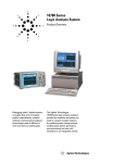
16700B-Series Logic Analysis
Systems
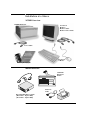
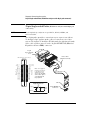
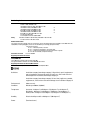
Installation at a Glance
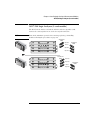
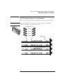
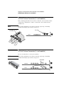
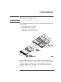
16700B Overview
16700B Mainframe
If ordered:
Monitor
Monitor Cable
Monitor Power Cable
Power Cable
Keyboard
& Mouse
Training Board & Kit
Additional Connections
16701A/B
Expander
Frame
Printer &
Cable
External Disk Drive & Cable
(Data Drive - Option 008)
(Boot Drive - Option 009)
2
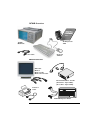
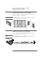
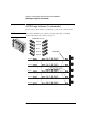
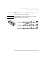
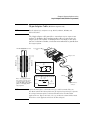
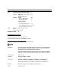
16702B Overview
Training Board
& Kit
16702B
Mainframe
Keyboard
& Mouse
Power Cable
Additional Connections
Orderable:
Monitor
Monitor Cable
Monitor Power Cable
External Disk Drive & Cable
(Data Drive - Option 008)
(Boot Drive - Option 009)
Printer &
Cable
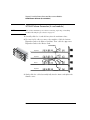
16701A/B Expander Frame
3
4
Contents
Installation at a Glance
1
General Information
9
To locate information on using the logic analyzer 10
To locate specifications and characteristics 11
To create a backup file of your system settings and license passwords
To reload system settings and license passwords 15
2
Connecting and Configuring Hardware
13
17
To connect the mouse, keyboard, and monitor 18
To configure a monitor for the 16700B 19
To configure an optional monitor for the 16702B 21
To change monitors (16700B or 16702B) 22
To connect to LAN 22
To connect a printer 24
To connect an external data drive (option 008) 26
To disconnect an external data drive (option 008) 30
To connect a removable boot drive (option 009) 31
To disconnect a removable boot drive (option 009) 34
To install software 34
To connect a 16701B expander frame 37
To connect multiple frames 38
To install, remove, or replace measurement modules 42
3
Installing Logic Analyzer
Measurement Modules
45
5
Contents
Software Requirements 46
16517/18A Logic Analyzer (2-card module) 47
16517/18A Logic Analyzer (3-card module) 48
16517/18A Logic Analyzer (4-card module) 49
16517/18A Logic Analyzer (5-card module) 50
16557D Logic Analyzer (1-card module) 50
16557D Logic Analyzer (2-card module) 51
16557D Logic Analyzer (3-card module) 52
16557D Logic Analyzer (3-card module) 53
16557D Logic Analyzer (5-card module) 54
16710/11/12A Logic Analyzer (1-card module) 55
16710/11/12A Logic Analyzer (2-card module) 56
16715/16/17A, 16718/19A, 16740/41/42A, 16750/51/52A/B Logic Analyzer (1card module) 57
16715/16/17A, 16718/19A, 16740/41/42A, 16750/51/52A/B Logic Analyzer (2card module) 58
16715/16/17A, 16718/19A, 16740/41/42A, 16750/51/52A/B Logic Analyzer (3card module) 59
16715/16/17A, 16718/19A, 16740/41/42A, 16750/51/52A/B Logic Analyzer (4card module) 60
16715/16/17A, 16718/19A, 16740/41/42A, 16750/51/52A/B Logic Analyzer (5card module) 61
16753/54/55/56A Logic Analyzer (1-card module) 62
16753/54/55/56A Logic Analyzer (2-card module) 63
16753/54/55/56A Logic Analyzer (3-card module) 64
16753/54/55/56A Logic Analyzer (4-card module) 65
16753/54/55/56A Logic Analyzer (5-card module) 66
16760A Logic Analyzer (1-card module) 67
16760A Logic Analyzer (2-card module) 67
16760A Logic Analyzer (3-card module) 68
16760A Logic Analyzer (4-card module) 69
16760A Logic Analyzer (5-card module) 70
4
Installing Oscilloscope
6
Contents
Measurement Modules
71
16533/34A Oscilloscope Module (single or multi-card modules)
5
Installing Pattern Generator
Measurement Modules
Software Requirements 88
16522A Pattern Generator (1-card module)
16522A Pattern Generator (2-card module)
16522A Pattern Generator (3-card module)
16522A Pattern Generator (4-card module)
16522A Pattern Generator (5-card module)
16720A Pattern Generator (1-card module)
16720A Pattern Generator (2-card module)
16720A Pattern Generator (3-card module)
16720A Pattern Generator (4-card module)
16720A Pattern Generator (5-card module)
6
Connecting Accessories
72
87
88
89
89
90
91
92
92
93
94
95
97
For More Information
General-purpose probing 99
Isolation adapter (Part number 01650-63203) 101
Direct connection 102
38-pin Low-voltage Probe (E5339A with tip isolation network) 103
38-pin Single-ended Probe (E5346A for analyzers with 40-pin pod
connectors) 104
38-pin Adapter Cable (E5351A no tip network) 105
100-pin Single-ended Probe (E5378A for analyzers with 90-pin pod
connectors) 106
7
Contents
100-pin Differential Probe (E5379A for analyzers with 90-pin pod
connectors) 107
38-pin Single-ended Probe (E5380A for analyzers with 90-pin pod
connectors) 108
Half-channel Adapter (E5386A) 109
Single-ended Flying Lead Probe Set (E5382A) 110
Soft Touch Probes (E5387A and E5390A for analyzers with 90-pin pod
connectors) 111
7
Troubleshooting
113
To run self-tests 114
To execute disaster recovery procedures
8
115
1
General Information
9
Chapter 1: General Information
To locate information on using the logic analyzer
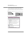
To locate information on using the logic analyzer
Go to on-line help for information on using your logic analyzer. A pdf file of the
on-line help is on the CD that came with your system if you want to print it
out.
1 Select Help in the upper right corner of the screen and then select On
Main System.
2 Select the task you need information about. .
10
Chapter 1: General Information
To locate specifications and characteristics
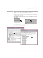
To locate specifications and characteristics
The specifications and characteristics for your instrument and measurement
module are in the on-line Help.
1 Select Help in the upper right corner of the screen and then select On
Main System.
2 Select Using Measurement Tools and then select your instrument or
measurement module from the list.
11
Chapter 1: General Information
To locate specifications and characteristics
3 Under Interface Reference, select Specifications and Characteristics.
12
Chapter 1: General Information
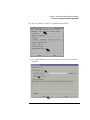
To create a backup file of your system settings and license passwords
To create a backup file of your system settings and
license passwords
By saving your system settings to a flexible disk or a mounted directory, you
create a backup file that can be used to quickly setup systems or to restore
current system settings in case of problems.
1 Insert a flexible disk or set up a mounted directory.
2 Select the Tools icon from the menu bar.
3 Select the Admin tab and select Save, then select Licenses and Save to
File.
13
Chapter 1: General Information
To create a backup file of your system settings and license passwords
4 Select Flexible Disk or a Mounted Directory and then select OK.
14
Chapter 1: General Information
To reload system settings and license passwords
To reload system settings and license passwords
1 Insert the flexible disk or set up a mounted directory.
2 Select the Tools icon from the menu bar.
3 Go to the Admin tab and select Load.
15
Chapter 1: General Information
To reload system settings and license passwords
4 Select Flexible Disk or Mounted Directory and select OK.
If an item is not valid, or was not initially saved to the file, the selection will be
grayed out in the interface. Also, if no file extension is added, a ‘.set’ extension
is automatically added for you.
16
2
Connecting and Configuring Hardware
17
Chapter 2: Connecting and Configuring Hardware
To connect the mouse, keyboard, and monitor
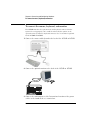
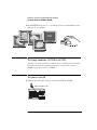
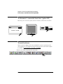
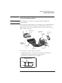
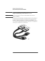
To connect the mouse, keyboard, and monitor
The 16700B must have the system mouse and keyboard connected for the
system to boot up properly. Once enabled on the LAN, the system can be
operated remotely without a keyboard or mouse. Use of a monitor is optional
for the 16700B and 16702B.
1 Connect the mouse and keyboard to the back of the 16700B or 16702B.
2 Connect the optional monitor to the back of the 16700B or 16702B.
3 Connect the monitor power cable. International versions of the power
cables can be found in the accessories box.
18
Chapter 2: Connecting and Configuring Hardware
To configure a monitor for the 16700B
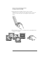
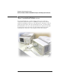
4 Allow a minimum of 5 cm spacing between instruments for proper
cooling.
5cm
5cm
16700B
5cm
5cm
16702B
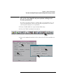
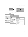
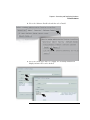
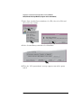
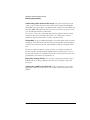
To configure a monitor for the 16700B
If you ordered the optional monitor with your logic analyzer, the monitor
resolution setting is pre-configured for 1280 x 1024 at the factory. Use this
procedure if you wish to configure an external monitor other than the optional
monitor orderable with the 16700B.
1 Connect your monitor to the logic analysis system as shown on page 18.
2 Turn on power to the monitor and then to the logic analysis system.
1
2
19
Chapter 2: Connecting and Configuring Hardware
To configure a monitor for the 16700B
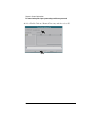
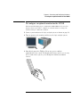
3 Immediately press the TAB key. Press once per second for
approximately 30 seconds. The monitor display will change on the screen
every few seconds as the system cycles through the monitor resolution
choices.
4 Press ENTER when you see a clear image to select your monitor choice
and type ‘Y” to confirm.
Clear
Images
20
Chapter 2: Connecting and Configuring Hardware
To configure an optional monitor for the 16702B
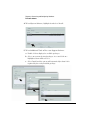
To configure an optional monitor for the 16702B
The internal LCD display is pre-configured for 800 x 600 at the factory. Use
this procedure if you wish to configure an external monitor or change the
monitor setting to a different resolution.
1 Connect your monitor to the logic analysis system as shown on page 18.
2 Turn on power to the monitor and then to the logic analysis system.
1
2
3 Immediately press the TAB key. Press once per second for
approximately 30 seconds. The display will change on the screen every
few seconds as the system cycles through the monitor resolution
choices.
21
Chapter 2: Connecting and Configuring Hardware
To change monitors (16700B or 16702B)
4 Press ENTER when you see a clear image to select your monitor choice
and type ‘Y” to confirm.
Clear
Images
To change monitors (16700B or 16702B)
Any time you change monitors you will need to re-configure the new monitor.
Follow the instructions beginning with step one on page 19 if you have a
16700B or page 21 if you have a 16702B.
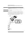
To connect to LAN
1 Connect the LAN cable to the back of the16700B or 16702B.
10Base-T/100Base-TX
22
Chapter 2: Connecting and Configuring Hardware
To connect to LAN
2 Go to the Help menu and select On Main System.
3 In the Help window select System Administration and then select
Configuring the Network. Follow the instructions on configuring the
network.
23
Chapter 2: Connecting and Configuring Hardware
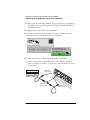
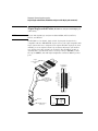
To connect a printer
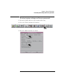
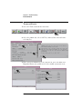
To connect a printer
1 Connect the printer cable to the back of your 16700B or 16702B.
2 Select the Tools icon from the menu bar.
3 Go to the Admin. tab and select Printers.
24
Chapter 2: Connecting and Configuring Hardware
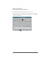
To connect a printer
4 If you are connecting a local printer, select Local, select your printer
type, select OK, and then Close.
(Your
printer)
5 If you are connecting a network printer, select Network, enter the
printer name, server address, select type, select OK, and then Close.
25
Chapter 2: Connecting and Configuring Hardware
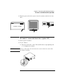
To connect an external data drive (option 008)
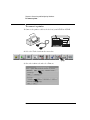
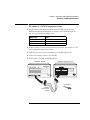
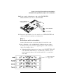
To connect an external data drive (option 008)
1 Power up the data drive.
2 Set the address.
a Unlock the data drive carrier. Wait until the drive stops spinning and
a “u” is displayed as shown.
CAUTION:
Damage could result to the data drive if it is removed from the carrier while
the number is flashing.
b Remove the data drive from the carrier.
26
Chapter 2: Connecting and Configuring Hardware
To connect an external data drive (option 008)
c Set the external data drive address to 3 or 4 using the alignment
tool supplied with the drive. The rotating switch is located inside
the carrier.
d Insert the disk drive into the carrier and lock it into place.
3 Power down the data drive.
27
Chapter 2: Connecting and Configuring Hardware
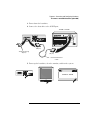
To connect an external data drive (option 008)
4 Connect the data drive to the SCSI-II port.
16700B or 16702B
(68 pin)
Termination Plug
(68 pin)
(50 pin)
External Disk Drive
Cable
5 Power up the data drive, then the monitor, and then the system
(16700B or 16702B).
16700A
16700B or 16702B
Power
Busy
6 Mount the disk.
a Select the Tools icon from the menu bar
28
Chapter 2: Connecting and Configuring Hardware
To connect an external data drive (option 008)
b Go to the Admin. tab and select Mount External Disk.
c Select SCSI Address to the same number set in step 2, then Mount,
and Close.
29
Chapter 2: Connecting and Configuring Hardware
To disconnect an external data drive (option 008)
To disconnect an external data drive (option 008)
It is important that you unmount the disk before turning the system off.
1 Select the Tools icon from the menu bar.
2 Select the Admin. tab, select Mount External Disk, select Unmount,
and then Close.
30
Chapter 2: Connecting and Configuring Hardware
To connect a removable boot drive (option 009)
3 Turn the power off on the system, then the monitor, and then the data
drive.
16700A
16700B or 16702B
Power
Busy
To connect a removable boot drive (option 009)
1 Power up the boot drive.
2 Set the address.
a Unlock the boot drive carrier. Wait until the drive stops spinning and
a “u” is displayed as shown.
CAUTION:
Damage could result to the data drive if it is removed from the carrier while
the number is flashing.
31
Chapter 2: Connecting and Configuring Hardware
To connect a removable boot drive (option 009)
b Remove the boot drive from the carrier.
c Set the external boot drive address to 6 using the alignment tool
supplied with the drive. The rotating switch is located inside the
carrier.
d Insert the disk into the carrier drive and lock it into place.
32
Chapter 2: Connecting and Configuring Hardware
To connect a removable boot drive (option 009)
3 Power down the boot drive.
4 Connect the boot drive to the SCSI-II port.
16700B or 16702B
(68 pin)
Termination Plug
(68 pin)
(50 pin)
External Disk Drive
Cable
5 Power up the boot drive, then the monitor, and then the system.
16700A
16700B or 16702B
Power
Busy
33
Chapter 2: Connecting and Configuring Hardware
To disconnect a removable boot drive (option 009)
To disconnect a removable boot drive (option 009)
Turn the power off on the system, then the monitor, and then the boot drive.
16700A
16700B or 16702B
Power
Busy
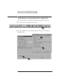
To install software
When a system is shipped, the factory installs the current operating system
and ordered processor support packages and tools. The latest software update
is available at www.software.cos.agilent.com/16700.
1 Select the Tools icon from the menu bar.
34
Chapter 2: Connecting and Configuring Hardware
To install software
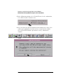
2 Select the Software Install tab and then select Install.
3 Select the media type and select Apply. The resulting window will
display software that can be loaded.
35
Chapter 2: Connecting and Configuring Hardware
To install software
4 To load System Software, highlight it and select Install.
5 To load Additional Tools or Processor Support Software:
a Double click to display the available packages.
b Select one or more desired packages. A second click on a
highlighted item will deselect it.
c Select Install and the system will automatically reboot if it is
required by the newly installed package.
36
Chapter 2: Connecting and Configuring Hardware
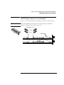
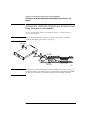
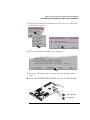
To connect a 16701B expander frame
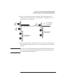
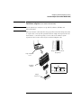
To connect a 16701B expander frame
1 Install your measurement modules in the 16701B expander frame.
Module installation instructions are on page 42. For information on
specific measurement modules go to:
Module Type
Page
Logic Analyzer
Oscilloscope
Pattern Generator
45
71
87
2 Connect either a 30 cm (12 inch) or 90 cm (36 inch) interconnect cable
to the expander and system frames.
3 Tighten the connector screws with the screwdriver provided.
4 Connect the power cable to the 16701B.
5 Power up the 16700B or 16702B system.
16700B or 16702B
16701B Expander Frame
Screwdriver
16701B
Interconnect
Cable
37
Chapter 2: Connecting and Configuring Hardware
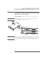
To connect multiple frames
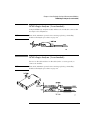
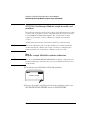
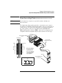
To connect multiple frames
As many as eight 16700B’s and/or 16702B’s with expander frames may be
connected together. To connect multiple frames you need to order 16700B
option #012 and/or 16702B option #012.
NOTE:
The multiframe module requires software Rev. A.02.00.00 or higher. Agilent
16700B and 16702B logic analysis systems ordered with the multiframe option
installed will have the current operating system software installed.
1 If the multiframe module is already installed, skip to step 11.
2 End your logic analysis session.
a Exit all logic analysis sessions. In the session manager, select
Shutdown.
b At the query, select Powerdown.
c When the “OK to turn off power or reset system” message appears,
turn the instrument off.
d Remove power from the instrument.
3 Disconnect the power cable and all data and peripheral cables from the
rear panel.
4 Move the instrument to a static-safe work area.
5 Lay the instrument on its side so the handle side is up.
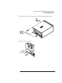
6 Using a Torx T10 screwdriver, remove two feet and one screw at the
center rear of the cover that secures the bottom cover to the frame.
38
Chapter 2: Connecting and Configuring Hardware
To connect multiple frames
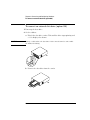
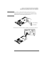
7 Slide the bottom cover toward the rear of the instrument and away..
8 Remove the cover plate.
39
Chapter 2: Connecting and Configuring Hardware
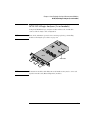
To connect multiple frames
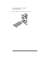
9 Insert the Multiframe Module with the cable attached.
16700e24.cdr
40
Chapter 2: Connecting and Configuring Hardware
To connect multiple frames
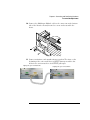
10 Connect the Multiframe Module cable to the connector on the bottom
side of the Interface Board, insert the screws and reassemble the
frame.
16700e25.cdr
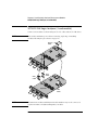
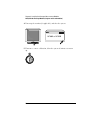
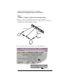
11 Connect mainframe and expander frames together.The frame at the
beginning of the series must have its INPUT port open and the last
frame in the series must have its OUTPUT port open.
Input port open on first frame
Output port open on last frame
41
Chapter 2: Connecting and Configuring Hardware
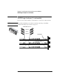
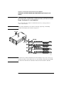
To install, remove, or replace measurement modules
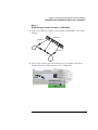
To install, remove, or replace measurement modules
CAUTION:
Electrostatic discharge can damage electronic components. Use grounded
wrist straps and mats when performing any service to measurement modules.
NOTE:
Measurement modules with different model numbers may not be connected
together in multi-card (Master/Expander) modules unless stated otherwise.
For information on specific measurement modules go to:
Module Type
Page
Logic Analyzer
Oscilloscope
Pattern Generator
45
71
87
1 Power down the system and disconnect the power cable before
installing, removing or replacing measurement modules.
Power
Busy
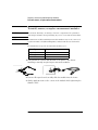
2 Remove filler panels and carefully slide the module into the frame.
3 Gently apply pressure to the center of the module while tightening the
thumb screws.
42
Chapter 2: Connecting and Configuring Hardware
To install, remove, or replace measurement modules
4 If you are inserting more than one module, the tightening order is
bottom module to top module. A single-module configuration can be
installed in any available slot.
Insert modules
or filler panels.
Remove filler panels.
(Other modules or
filler panels.)
(Other modules or
filler panels.)
5 Some modules require calibration if they are moved to a different slot.
For calibration information, refer to the on-line help for the individual
modules.
WARNING:
For correct air circulation, filler panels must be installed in all unused card
slots. Correct air circulation keeps the instrument from overheating. Keep
any extra filler panels for future use.
43
Chapter 2: Connecting and Configuring Hardware
To install, remove, or replace measurement modules
44
3
Installing Logic Analyzer
Measurement Modules
45
Chapter 3: Installing Logic Analyzer Measurement Modules
Software Requirements
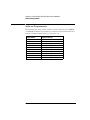
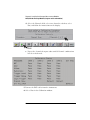
Software Requirements
The following table gives you the software version required in your 16700A/B
or 16702A/B mainframe for use with logic analyzer measurement modules. For
software installation instructions go to page page 34.
Model Number
Software Version
16517/18A
16557D
16710/11/12A
16715/16/17A
16718/19A
16740/41/42A
16750/51/52A
16750/51/52B
16753/54/55/56A
16760A
All versions
All versions
A.01.20.00 or higher
A.01.40.00 or higher
A.01.50.00 or higher
A.02.50.00 or higher
A.02.00.00 or higher
A.02.50.00 or higher
A.02.70.00 or higher
A.02.20.00 or higher
46
Chapter 3: Installing Logic Analyzer Measurement Modules
16517/18A Logic Analyzer (2-card module)
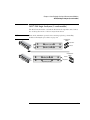
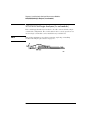
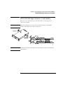
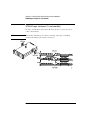
16517/18A Logic Analyzer (2-card module)
The 16517A is the master card and the 16518A is the expander card. Connect
the cards together in one of the two ways shown below.
NOTE:
Turn off the mainframe power before removing, replacing, or installing
modules following the procedures on page 42.
2 Connector
Cable
Expander
Expander (16518A)
Master
Master (16517A)
2 Connector
Cable
Master (16517A)
Master
Expander
Expander (16518A)
47
Chapter 3: Installing Logic Analyzer Measurement Modules
16517/18A Logic Analyzer (3-card module)
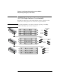
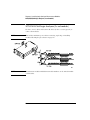
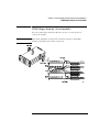
16517/18A Logic Analyzer (3-card module)
The 16517A is the master card and the 16518A cards are expander cards.
Connect the cards together in one of the three ways shown below.
NOTE:
Turn off the mainframe power before removing, replacing, or installing
modules following the procedures on page 42.
Master (16517A)
Expander (16518A)
Expander (16518A)
3 Connector
Cable
Master
Expander
Expander
2 Connector
Cable
Expander (16518A)
Master (16517A)
Expander 2 Connector
Cable
Master
Expander
Expander (16518A)
3 Connector
Cable
Expander
Expander (16518A)
Expander
Expander (16518A)
Master
Master (16517A)
48
Chapter 3: Installing Logic Analyzer Measurement Modules
16517/18A Logic Analyzer (4-card module)
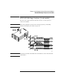
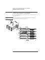
16517/18A Logic Analyzer (4-card module)
The 16517A is the master card and the 16518A cards are expander cards.
Connect the cards together in one of the two ways shown below.
NOTE:
Turn off the mainframe power before removing, replacing, or installing
modules following the procedures on page 42.
2 Connector
Cable
Expander
Expander (16518A)
3 Connector
Cable
Master
Master (16517A)
Expander
Expander (16518A)
Expander
Expander (16518A)
3 Connector
Cable
Expander (16518A)
Expander
Expander (16518A)
Expander
Master (16517A)
Expander (16518A)
Master
2 Connector
Cable
Expander
49
Chapter 3: Installing Logic Analyzer Measurement Modules
16517/18A Logic Analyzer (5-card module)
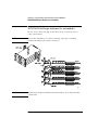
16517/18A Logic Analyzer (5-card module)
The 16517A is the master card and the 16518A cards are expander cards.
Connect the cards together as shown below.
NOTE:
Turn off the mainframe power before removing, replacing, or installing
modules following the procedures on page 42.
3 Connector
Cable
Expander (16518A)
Expander
Expander (16518A)
Expander
Master (16517A)
Expander (16518A)
3 Connector
Cable
Master
Expander
Expander
Expander (16518A)
16557D Logic Analyzer (1-card module)
When ordered as a single card, the 16557D is shipped with a 2 x 10 cable
factory configured as a single-card module.
NOTE:
Turn off the mainframe power before removing, replacing, or installing
modules following the procedures on page 42.
2x10 Cable
Master
50
Chapter 3: Installing Logic Analyzer Measurement Modules
16557D Logic Analyzer (2-card module)
16557D Logic Analyzer (2-card module)
Use two 2 x 25 cables and two 2 x 10 cables to connect the cards as shown.
NOTE:
Turn off the mainframe power before removing, replacing, or installing
modules following the procedures on page 42.
2x25 Cables (Need 2)
Expander
Master
2x10 Cables
Expander
Master
51
Chapter 3: Installing Logic Analyzer Measurement Modules
16557D Logic Analyzer (3-card module)
16557D Logic Analyzer (3-card module)
Use two 2 x 25 cables and three 2 x 10 cables to connect the cards as shown.
NOTE:
Turn off the mainframe power before removing, replacing, or installing
modules following the procedures on page 42.
2x25 Cables (Need 2)
Expander
Master
Expander
2x10 Cables
Expander
Master
Expander
52
Chapter 3: Installing Logic Analyzer Measurement Modules
16557D Logic Analyzer (3-card module)
16557D Logic Analyzer (3-card module)
Use two 2 x 25 cables and four 2 x 10 cables to connect the cards as shown.
NOTE:
Turn off the mainframe power before removing, replacing, or installing
modules following the procedures on page 42.
2x25 Cables (Need 2)
Expander
Expander
Master
Expander
2x10 Cables
Expander
Expander
Master
Expander
53
Chapter 3: Installing Logic Analyzer Measurement Modules
16557D Logic Analyzer (5-card module)
16557D Logic Analyzer (5-card module)
Use two 2 x 25 cables and five 2 x 10 cables to connect the cards as shown.
NOTE:
Turn off the mainframe power before removing, replacing, or installing
modules following the procedures on page 42.
2x25 Cables (Need 2)
Expander
Expander
Master
Expander
Expander
Expander
Expander
Master
Expander
Expander
54
2x10 Cables
Chapter 3: Installing Logic Analyzer Measurement Modules
16710/11/12A Logic Analyzer (1-card module)
16710/11/12A Logic Analyzer (1-card module)
A single 16710/11/12A logic analyzer module will have the 2 x 40 cable
connected in the single-card configuration.
NOTE:
Turn off the mainframe power before removing, replacing, or installing
modules following the procedures on page 42.
J9
J7
J8
Master
2x40 Cable
NOTE:
Measurement modules with different model numbers may not be connected
together in multi-card (Master/Expander) modules.
55
Chapter 3: Installing Logic Analyzer Measurement Modules
16710/11/12A Logic Analyzer (2-card module)
16710/11/12A Logic Analyzer (2-card module)
Connect two modules as shown using two 2 x 25 cables and two 2 x 40 cables.
NOTE:
Turn off the mainframe power before removing, replacing, or installing
modules following the procedures on page 42.
2x40
Cable
J6
J5
J9
J7
J8
Master
2x25
Cable
2x25
Cable
J6
J5
J9
J7
J8
Expander
2x40
Cable
NOTE:
Measurement modules with different model numbers may not be connected
together in multi-card (Master/Expander) modules.
56
Chapter 3: Installing Logic Analyzer Measurement Modules
16715/16/17A, 16718/19A, 16740/41/42A, 16750/51/52A/B Logic Analyzer (1-card module)
16715/16/17A, 16718/19A, 16740/41/42A, 16750/51/52A/B
Logic Analyzer (1-card module)
Each card shipped stand-alone has the 2 x 10 cable connected in the singlecard module configuration. A single-card module can be installed in any
available slot.
NOTE:
Turn off the mainframe power before removing, replacing, or installing
modules following the procedures on page 42.
NOTE:
Measurement modules with different model numbers may not be connected
together in multi-card (Master/Expander) modules.
57
Chapter 3: Installing Logic Analyzer Measurement Modules
16715/16/17A, 16718/19A, 16740/41/42A, 16750/51/52A/B Logic Analyzer (2-card
module)
16715/16/17A, 16718/19A, 16740/41/42A, 16750/51/52A/B
Logic Analyzer (2-card module)
Use two 2 x 10 cables and two 2 x 40 cables (in the accessory pouch) to
connect the modules.
NOTE:
Turn off the mainframe power before removing, replacing, or installing
modules following the procedures on page 42.
NOTE:
Measurement modules with different model numbers may not be connected
together in multi-card modules. However, the 16750A works with the 16750B;
the 16751A works with the 16751B; the 16752A works with the 16752B.
58
Chapter 3: Installing Logic Analyzer Measurement Modules
16715/16/17A, 16718/19A, 16740/41/42A, 16750/51/52A/B Logic Analyzer (3-card module)
16715/16/17A, 16718/19A, 16740/41/42A, 16750/51/52A/B
Logic Analyzer (3-card module)
Use three 2 x 10 cables and four 2 x 40 cables (in the accessory pouch) to
connect the modules.
NOTE:
Turn off the mainframe power before removing, replacing, or installing
modules following the procedures on page 42.
NOTE:
Measurement modules with different model numbers may not be connected
together in multi-card modules. However, the 16750A works with the 16750B;
the 16751A works with the 16751B; the 16752A works with the 16752B.
59
Chapter 3: Installing Logic Analyzer Measurement Modules
16715/16/17A, 16718/19A, 16740/41/42A, 16750/51/52A/B Logic Analyzer (4-card
module)
16715/16/17A, 16718/19A, 16740/41/42A, 16750/51/52A/B
Logic Analyzer (4-card module)
Use four 2 x 10 cables and six 2 x 40 cables (in the accessory pouch) to
connect the modules.
NOTE:
Turn off the mainframe power before removing, replacing, or installing
modules following the procedures on page 42
NOTE:
Measurement modules with different model numbers may not be connected
together in multi-card modules. However, the 16750A works with the 16750B;
the 16751A works with the 16751B; the 16752A works with the 16752B.
60
Chapter 3: Installing Logic Analyzer Measurement Modules
16715/16/17A, 16718/19A, 16740/41/42A, 16750/51/52A/B Logic Analyzer (5-card module)
16715/16/17A, 16718/19A, 16740/41/42A, 16750/51/52A/B
Logic Analyzer (5-card module)
Use five 2 x 10 cables and eight 2 x 40 cables (in the accessory pouch) to
connect the modules
NOTE:
Turn off the mainframe power before removing, replacing, or installing
modules following the procedures on page 42.
NOTE:
Measurement modules with different model numbers may not be connected
together in multi-card modules. However, the 16750A works with the 16750B;
the 16751A works with the 16751B; the 16752A works with the 16752B.
61
Chapter 3: Installing Logic Analyzer Measurement Modules
16753/54/55/56A Logic Analyzer (1-card module)
16753/54/55/56A Logic Analyzer (1-card module)
Each card shipped stand-alone has the 2 x 15 cable connected in the singlecard module configuration. The 2 x 50 cables in the accessory pouch are not
used. A single-card module can be installed in any available slot.
NOTE:
Turn off the mainframe power before removing, replacing, or installing
modules following the procedures on page 42.
62
Chapter 3: Installing Logic Analyzer Measurement Modules
16753/54/55/56A Logic Analyzer (2-card module)
16753/54/55/56A Logic Analyzer (2-card module)
Use two 2 x 15 cables and two 2 x 50 cables (in the accessory pouch) to
connect the modules.
NOTE:
Turn off the mainframe power before removing, replacing, or installing
modules following the procedures on page 42.
NOTE:
Measurement modules with different model numbers can be mixed in multicard modules.
63
Chapter 3: Installing Logic Analyzer Measurement Modules
16753/54/55/56A Logic Analyzer (3-card module)
16753/54/55/56A Logic Analyzer (3-card module)
Use three 2 x 15 cables and four 2 x 50 cables (in the accessory pouch) to
connect the modules.
NOTE:
Turn off the mainframe power before removing, replacing, or installing
modules following the procedures on page 42.
NOTE:
Measurement modules with different model numbers can be mixed in multicard modules.
64
Chapter 3: Installing Logic Analyzer Measurement Modules
16753/54/55/56A Logic Analyzer (4-card module)
16753/54/55/56A Logic Analyzer (4-card module)
Use four 2 x 15 cables and six 2 x 50 cables (in the accessory pouch) to
connect the modules.
NOTE:
Turn off the mainframe power before removing, replacing, or installing
modules following the procedures on page 42
NOTE:
Measurement modules with different model numbers can be mixed in multicard modules.
65
Chapter 3: Installing Logic Analyzer Measurement Modules
16753/54/55/56A Logic Analyzer (5-card module)
16753/54/55/56A Logic Analyzer (5-card module)
Use five 2 x 15 cables and eight 2 x 50 cables (in the accessory pouch) to
connect the modules
NOTE:
Turn off the mainframe power before removing, replacing, or installing
modules following the procedures on page 42.
NOTE:
Measurement modules with different model numbers can be mixed in multicard modules.
66
Chapter 3: Installing Logic Analyzer Measurement Modules
16760A Logic Analyzer (1-card module)
16760A Logic Analyzer (1-card module)
A single 16760A logic analyzer module will have the 2 x 10 cable connected in
the single-card configuration.
NOTE:
Turn off the mainframe power before removing, replacing, or installing
modules following the procedures on page 42.
16760A Logic Analyzer (2-card module)
Use two 2 x 10 cables and two 2 x 40 cables (in the accessory pouch) to
connect the modules.
NOTE:
Turn off the mainframe power before removing, replacing, or installing
modules following the procedures on page 42.
67
Chapter 3: Installing Logic Analyzer Measurement Modules
16760A Logic Analyzer (3-card module)
16760A Logic Analyzer (3-card module)
Use three 2 x 10 cables and four 2 x 40 cables (in the accessory pouch) to
connect the modules.
NOTE:
Turn off the mainframe power before removing, replacing, or installing
modules following the procedures on page 42.
68
Chapter 3: Installing Logic Analyzer Measurement Modules
16760A Logic Analyzer (4-card module)
16760A Logic Analyzer (4-card module)
Use four 2 x 10 cables and six 2 x 40 cables (in the accessory pouch) to
connect the modules.
NOTE:
Turn off the mainframe power before removing, replacing, or installing
modules following the procedures on page 42.
69
Chapter 3: Installing Logic Analyzer Measurement Modules
16760A Logic Analyzer (5-card module)
16760A Logic Analyzer (5-card module)
Use five 2 x 10 cables and eight 2 x 40 cables (in the accessory pouch) to
connect the modules.
NOTE:
Turn off the mainframe power before removing, replacing, or installing
modules following the procedures on page 42.
70
4
Installing Oscilloscope
Measurement Modules
71
Chapter 4: Installing Oscilloscope Measurement Modules
16533/34A Oscilloscope Module (single or multi-card modules)
16533/34A Oscilloscope Module (single or multi-card
modules)
The Agilent Technologies 16533A/34A oscilloscope module functions as either
a master card or expander card. It is compatible with all versions of software
in your 16700A/B or 16702A/B mainframe. The circuitry in the module
requires an operational accuracy calibration to optimize measurement
accuracy.
A multicard module should contain either all 16533A or 16534A cards.
NOTE:
Each of the individual cards of a multicard 16533A or a multicard 16534A
module must first be calibrated as a single card. After reconfiguring into a
multicard module, the channel skew calibration needs to be done.
Step 1
Prepare a single 16533/34A card for calibration
CAUTION:
The effects of ELECTROSTATIC DISCHARGE can damage components. Use
grounded wrist straps and mats when you are performing any kind of service
on this module.
1 Power down your 16700A/B or 16702A/B mainframe.
16700A
16700B or 16702B
Power
Busy
2 Remove all modules and filler panels from the mainframe and set the
PROTECTED/UNPROTECTED switch to UNPROTECTED.
72
Chapter 4: Installing Oscilloscope Measurement Modules
16533/34A Oscilloscope Module (single or multi-card modules)
NOTE:
If you calibrate a module without unprotecting the memory, the new
calibration settings will not be saved when the system is shut down. The
system will default to the previous settings. The new calibration settings
would be effective for the current active session only.
UNPROTECTED
PROTECTED
3 Reinstall the 16533/34A modules and filler panels into the mainframe.
73
Chapter 4: Installing Oscilloscope Measurement Modules
16533/34A Oscilloscope Module (single or multi-card modules)
4 Power up the monitor (if applicable) and then the system.
1 670 0A
16700B or 16702B
Power
Busy
5 For more accurate calibration, allow the system 30 minutes to warm
up.
0
15
30
74
Chapter 4: Installing Oscilloscope Measurement Modules
16533/34A Oscilloscope Module (single or multi-card modules)
Step 2
Perform operational accuracy calibration
1 Connect the BNC Tee and the (equal length) 50-ohm BNC cables to the
module.
AC/DC Cal
Channel 1
Channel 2
2 In the Logic Analysis System window, select the module icon for the
16533A/34A to be calibrated, then select Calibration.
$
75
Chapter 4: Installing Oscilloscope Measurement Modules
16533/34A Oscilloscope Module (single or multi-card modules)
3 In the Calibration window, select Default Factors. At the confirmation,
select OK to load the default factors.
4 Select the Run icon and the instrument will remind you to connect the
cables to the appropriate locations on the rear panel of the module.
Select OK and wait until the operational accuracy calibration is
complete.
RUN
76
Chapter 4: Installing Oscilloscope Measurement Modules
16533/34A Oscilloscope Module (single or multi-card modules)
As operational accuracy calibration runs, messages appear in the message box
on screen.
The Calibration Status window indicates pass or fail as each operational
accuracy calibration routine is completed. The resulting calibration factors are
automatically stored to non-volatile RAM at the conclusion of each calibration
routine.
77
Chapter 4: Installing Oscilloscope Measurement Modules
16533/34A Oscilloscope Module (single or multi-card modules)
Step 3
Calibrate a single card for external trigger skew
1 Connect a 9-inch 50-ohm BNC cable to one side of the BNC tee
adapter. On the other side of the BNC tee adapter connect a 9-inch 50ohm BNC and a BNC(f)/SMB(m) adapter.
AC/DC Cal
Channel 1
ECL
External
Trigger In
BNC/SMB
Adapter
2 Select the Procedure field and then select Ext Trig Skew.
78
Chapter 4: Installing Oscilloscope Measurement Modules
16533/34A Oscilloscope Module (single or multi-card modules)
3 Select the Run icon and the instrument will remind you to connect the
cables. Select OK and wait for the trigger skew calibration to complete.
RUN
As trigger skew calibration runs, messages appear in the message box on
screen. When the Ext Trig Skew calibration is complete, the resulting
calibration factors are stored in non-volatile RAM.
4 If a multi-card module is being calibrated, repeat the procedures
beginning with Step 1 on page 72 for each card until all cards have been
calibrated.
5 If all cards have been calibrated, remove the BNC cables from the
instrument.
6 Select Close in the Calibration window.
79
Chapter 4: Installing Oscilloscope Measurement Modules
16533/34A Oscilloscope Module (single or multi-card modules)
7 In the Logic Analysis System window select File, then select Exit and
OK to close the session.
8 In the Session Manager window select Shutdown.
9 When the “OK to powerdown” message appears, turn off the power
switch.
80
Chapter 4: Installing Oscilloscope Measurement Modules
16533/34A Oscilloscope Module (single or multi-card modules)
10 If you are only calibrating one card set the PROTECTED/
UNPROTECTED switch back to PROTECTED.
If only calibrating one
card set protect.
UNPROTECTED
PROTECTED
11 For multi-card modules, leave the switch set to UNPROTECTED and
continue to Step 4 to perform reconfiguration.
Step 4
Reconfigure multi-card modules
A multicard module should contain either all 16533A or 16534A cards.
1 After calibrating each card individually (following the procedures
beginning on page 72) and before applying power to the mainframe,
connect the module cables.
a Beginning with the top-most card, connect the ECL EXT TRIG OUT
to the ECL EXT TRIG IN of the card immediately below. Use the
master/expander trigger cable included with the accessory kit of
each card.
Master/expander
trigger cables
81
Chapter 4: Installing Oscilloscope Measurement Modules
16533/34A Oscilloscope Module (single or multi-card modules)
b Repeat for all cards in the module. Up to 4 cards may be configured
on a single time base and trigger in a 16700A, 16700B, 16702A, or
16702B mainframe
2 Reapply power to the 16700-series mainframe.
3 In the Logic Analysis System window select the icon for the master
card of the multi-card module then select Calibration.
$
4 Perform channel skew calibration on the multi-card module.
a Connect two 9-inch 50-ohm BNC cables and a BNC tee adapter
between channel 1, AC/DC cal, of the first card and channel 1 of the
second card.
Chan. 1
Chan. 2
Chan. 1
Chan. 2
Channel 1
Upper Card
AC/CD Cal
Upper Card
82
Channel 1
Lower Card
Chapter 4: Installing Oscilloscope Measurement Modules
16533/34A Oscilloscope Module (single or multi-card modules)
b Select the Procedure field and then select Ext Trig Skew.
c Select Run and the instrument will remind you to connect the
cables. Select OK and the Calibration window opens.
RUN
83
Chapter 4: Installing Oscilloscope Measurement Modules
16533/34A Oscilloscope Module (single or multi-card modules)
d Select the Channels field, select two channels to deskew, select
Run, and follow the instructions on the display.
RUN
e Repeat the channel skew procedure until all channel combinations
have been deskewed.
5 Remove the BNC cables from the instrument.
6 Select Close in the Calibration window.
84
Chapter 4: Installing Oscilloscope Measurement Modules
16533/34A Oscilloscope Module (single or multi-card modules)
7 In the Logic Analysis System window select File, then select Exit and
OK to close the session.
8 In the Session Manager window select Shutdown.
9 When the “OK to powerdown” message appears, turn off the power
switch.
10 Set the PROTECTED/UNPROTECTED switch back to PROTECTED.
UNPROTECTED
PROTECTED
85
86
5
Installing Pattern Generator
Measurement Modules
87
Chapter 5: Installing Pattern Generator Measurement Modules
Software Requirements
Software Requirements
The following table gives you the software version required in your 16700A/B
or 16702A/B mainframe for use with pattern generator measurement modules.
For software installation instructions go to page page 34.
Model Number
Software Version
16522A
16720A
All versions
A.02.00.00 or higher
16522A Pattern Generator (1-card module)
Each 16522A shipped stand-alone has the 2 x 10 cable connected in the
single-card module configuration. A single-card module can be installed in any
available slot.
NOTE:
Turn off the mainframe power before removing, replacing, or installing
modules following the procedures on page 42.
2x10 cable
Master
88
Chapter 5: Installing Pattern Generator Measurement Modules
16522A Pattern Generator (2-card module)
16522A Pattern Generator (2-card module)
Use two 2 x 10 cables to connect the modules as shown.
NOTE:
Turn off the mainframe power before removing, replacing, or installing
modules following the procedures on page 42.
2x10 Cable
Expander
Master
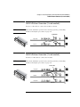
16522A Pattern Generator (3-card module)
Use three 2 x 10 cables to connect the modules.
NOTE:
Turn off the mainframe power before removing, replacing, or installing
modules following the procedures on page 42.
2x10 Cable
Expander
Master
Expander
89
Chapter 5: Installing Pattern Generator Measurement Modules
16522A Pattern Generator (4-card module)
16522A Pattern Generator (4-card module)
NOTE:
Turn off the mainframe power before removing, replacing, or installing
modules following the procedures on page 42.
1 Carefully slide the 4 cards half way into the mainframe slots.
2 Use four 2 x 10 cables to connect the modules. Cable the bottom
Expander Card to the Master Card first. Then cable the upper two
Expander Cards to the Master Card.
2x10 Cable
Expander
Expander
Master
Expander
3 Gently slide the cabled assembly fully into the frame and tighten the
thumb screws.
90
Chapter 5: Installing Pattern Generator Measurement Modules
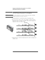
16522A Pattern Generator (5-card module)
16522A Pattern Generator (5-card module)
NOTE:
Turn off the mainframe power before removing, replacing, or installing
modules following the procedures on page 42.
1 Carefully slide the 4 cards half way into the mainframe slots.
2 Use five 2 x 10 cables to connect the modules. Cable the bottom
Expander Card to the Master Card first. Then cable the upper two
Expander Cards to the Master Card.
2x10 Cable
Expander
Expander
Master
Expander
Expander
3 Gently slide the cabled assembly fully into the frame and tighten the
thumb screws.
91
Chapter 5: Installing Pattern Generator Measurement Modules
16720A Pattern Generator (1-card module)
16720A Pattern Generator (1-card module)
Each card shipped stand-alone has the 2 x 10 cable connected in the singlecard module configuration. A single-card module can be installed in any
available slot.
NOTE:
Turn off the mainframe power before removing, replacing, or installing
modules following the procedures on page 42.
2x10 cable
2x10 cable connection
for a single-card
Master
16720A Pattern Generator (2-card module)
Use two 2 x 10 cables to connect the modules.
NOTE:
Turn off the mainframe power before removing, replacing, or installing
modules following the procedures on page 42.
2x10 Cable
Expander
Master
92
Chapter 5: Installing Pattern Generator Measurement Modules
16720A Pattern Generator (3-card module)
16720A Pattern Generator (3-card module)
Use three 2 x 10 cables to connect the modules.
NOTE:
Turn off the mainframe power before removing, replacing, or installing
modules following the procedures on page 42.
2x10 Cable
Expander
Master
Expander
93
Chapter 5: Installing Pattern Generator Measurement Modules
16720A Pattern Generator (4-card module)
16720A Pattern Generator (4-card module)
NOTE:
Turn off the mainframe power before removing, replacing, or installing
modules following the procedures on page 42.
1 Carefully slide the 4 cards half way into the mainframe slots.
2 Use four 2 x 10 cables to connect the modules. Cable the bottom
Expander Card to the Master Card first. Then cable the upper two
Expander Cards to the Master Card.
2x10 Cable
Expander
Expander
Master
Expander
3 Gently slide the cabled assembly fully into the frame and tighten the
thumb screws.
94
Chapter 5: Installing Pattern Generator Measurement Modules
16720A Pattern Generator (5-card module)
16720A Pattern Generator (5-card module)
NOTE:
Turn off the mainframe power before removing, replacing, or installing
modules following the procedures on page 42.
1 Carefully slide the 4 cards half way into the mainframe slots.
2 Use six 2 x 10 cables to connect the modules. Cable the bottom two
Expander Cards to the Master Card first. Then cable the upper two
Expanders to the Master Card.
2x10 Cable
Expander
Expander
Master
Expander
Expander
3 Gently slide the cabled assembly fully into the frame and tighten the
thumb screws.
95
96
6
Connecting Accessories
97
Chapter 6: Connecting Accessories
For More Information
The following sections give you an overview of Agilent Technologies probes
and time correlation fixture.
More information on probing options can be found in a document titled
Probing Solutions for Logic Analysis Systems which you can download from
www.agilent.com. In the search box type ‘Probing Solutions for Logic Analysis
Systems’ and select go. Scroll down to Datasheets, Demonstrations, &
Catalogs to find the document.
Detailed information on specific probes or the time correlation fixture can be
found in the documentation that comes with the product. Product
documentation can also be downloaded from http://www.tm.agilent.com/
classes/ProdSearch. Type in the model number or product name and select go.
Scroll down to Manuals, Guides & Service Notes to find these documents.
98
Chapter 6: Connecting Accessories
General-purpose probing
General-purpose probing
NOTE:
For all Agilent logic analyzers except 16517A, 16518A, 16760A, and
16753/54/55/56A.
General-purpose probing requires connecting probe leads to individual signal
lines. It is generally the most cumbersome method but it is also the most
flexible. There are no active circuits at the outer end of the cable due to the
passive design of the probe.
Logic Analyzer
Pod
Ground Lead
(Short)
Ground Lead
(Long)
Probe Tip
Assembly
01650-61608
Probe
Housing
Probe Tip
Probe Lead
The advantages of general-purpose probing are:
•
High-input impedance as shown in the equivalent load model below.
•
Signal ground at the probe tip for high-speed signals.
•
Inexpensive, removable probe tip assemblies.
Equivalent Load
370
ohm
Signal
1.5pF
7.4pF
100k
ohm
Ground
Includes logic analyzer
99
Chapter 6: Connecting Accessories
General-purpose probing
Connecting probe leads to the target. The signal and ground leads
can be connected directly to the target system. This requires installing 0.63
mm (0.025 inch) square pins, or round pins with a diameter between 0.66 and
0.84 mm (0.026 and 0.033 inch) directly on the board. You can also use an IC
test clip with pins with those dimensions.
You can also connect the leads using through-hole grabbers that have small
enough hooks to fit around adjacent IC pins, or by using surface-mount
grabbers designed for fine surface-mount component leads.
Grounding. Proper grounding will improve the signal quality and is essential
for high speed measurements. Each pod has a pod ground lead, which must be
used. If you use this ground only, signal quality for high speed signals will be
poor.
For better results, ground not only the pod, but every third or fourth lead.
For best results, and when probing signals with rise and fall times of 1 ns or
less, ground each probe lead with no more than a 2-inch ground lead as well as
grounding the pod with the pod ground lead.
Replacing damaged leads. You can replace damaged leads. Disconnect
individual probe leads by pushing on the latch at the lead base with a ballpoint pen.
Connecting grabbers to the leads. Connect grabbers to the leads by
slipping the end of the lead over the recessed pin located in the side of the
grabber.
100
Chapter 6: Connecting Accessories
Isolation adapter (Part number 01650-63203)
Isolation adapter (Part number 01650-63203)
NOTE:
For all Agilent logic analyzers except 16517A, 16518A, 16760A, and
16753/54/55/56A.
The logic analyzer cable must have the proper RC network at its input in order
to acquire data correctly. The optional Isolation Adapter incorporates the RC
network into a convenient package. It also reduces the number of pins
required for the header on the target board from 40 pins to 20.
+5V
CLK1
D14
D12
D10
D8
D6
D4
D2
D0
1
3
5
7
9
11
13
15
17
19
2
4
6
8
10
12
14
16
18
20
N/C
D15
D13
D11
D9
D7
D5
D3
D1
GND
Target Connector Pinout
(Top View)
Logic Analyzer
Pod
Equivalent Load
Isolation
Adapter
370
ohm
Signal
4.6pF
7.4pF
100k
ohm
Ground
Includes logic analyzer
Target
Connector
101
Chapter 6: Connecting Accessories
Direct connection
Direct connection
NOTE:
For all Agilent logic analyzers except 16517A, 16518A, 16760A, and
16753/54/55/56A.
You can connect the logic analyzer cable directly to a 40-pin connector, but
you must install the proper isolation network directly onto the target system
board.
CAUTION:
If drawing current from the 5V supply, do not exceed 0.33 amps per cable. The
cable ground lines are chassis (earth) grounds and not "floating" grounds. All
the lines are woven into a flat ribbon that is 137.16 cm (4.5 feet) long.
NOTE:
Agilent Technologies recommends two types of RC networks. They are
described in detail in Probing Solutions for Agilent Logic Analysis Systems.
Go to http://www.tm.agilent.com/classes/ProdSearch to download this
application note. Type in the title, select go, and the document will be listed
under the section Application Notes & Technical Papers.
Logic Analyzer
Pod
+5V
CLK1
N/C
D15
D14
D13
D12
D11
D10
D9
D8
D7
D6
D5
D4
D3
D2
D1
D0
+5V
1
3
5
7
9
11
13
15
17
19
21
23
25
27
29
31
33
35
37
39
2
4
6
8
10
12
14
16
18
20
22
24
26
28
30
32
34
36
38
40
Power GND
Signal GND
Signal GND
Signal GND
Signal GND
Signal GND
Signal GND
Signal GND
Signal GND
Signal GND
Signal GND
Signal GND
Signal GND
Signal GND
Signal GND
Signal GND
Signal GND
Signal GND
Signal GND
Power GND
Target Connector Pinout
(Top View)
102
Suggested On-board RC Network
250
ohm
90.9k
ohm
Signal
8.2pF
To Logic
Analyzer
Pod
Ground
Equivalent Load
370
ohm
Signal
0.3pF
7.4pF
100k
ohm
Ground
Includes on-board isolation network and logic analyzer
Chapter 6: Connecting Accessories
38-pin Low-voltage Probe (E5339A with tip isolation network)
38-pin Low-voltage Probe (E5339A with tip isolation network)
NOTE:
For all Agilent logic analyzers except 16517A, 16518A, 16760A, and
16753/54/55/56A.
The 38-pin low-voltage probe provides a convenient way to connect
two Agilent Technologies logic analyzer probe cables to a small area of
a target system. The Agilent E5339A probe has isolation networks in
the cable end that connects to the high-density AMP MICTOR
(Matched Impedance ConnecTOR) connector. It is designed to be
compatible with low-amplitude digital signals, down to 250 mV p-p.
Logic Analyzer
Pod
AMP "MICTOR 38"
Connector Pinout
Probe Cable
(with RC network)
1
3
5
7
9
11
13
15
17
19
21
23
25
27
29
31
33
35
37
2
4
6
8
10
12
14
16
18
20
22
24
26
28
30
32
34
36
38
Do not connect
Do not connect
CLK
D15
D14
D13
D12
D11
D10
D9
D8
D7
D6
D5
D4
D3
D2
D1
D0
Odd Pod
Even Pod
+5VDC
GND DC
CLK
D15
D14
D13
D12
D11
D10
D9
D8
D7
D6
D5
D4
D3
D2
D1
D0
Note: +5V is supplied
from the logic analyzer
to provide power for
analysis probes and
demo boards. DO NOT
connect these pins to
a +5V supply in the
target system!
Shroud
Amp "MICTOR 38”
Connector
Equivalent Load
220
ohm
Signal
3pF
18pF
50.5k
ohm
Ground
Includes logic analyzer and MICTOR connector.
103
Chapter 6: Connecting Accessories
38-pin Single-ended Probe (E5346A for analyzers with 40-pin pod connectors)
38-pin Single-ended Probe (E5346A for analyzers with 40-pin pod
connectors)
NOTE:
For all Agilent logic analyzers except 16517A, 16518A, 16760A, and
16753/54/55/56A.
The 38-pin probe provides a convenient way to connect two Agilent
Technologies logic analyzer probe cables to a small area of a target
system. The Agilent Technologies E5346A probe has isolation networks
in the cable end that connects to the 38-pin AMP MICTOR (Matched
Impedance ConnecTOR) connector.
40-pin
Logic Analyzer
Pod
Probe Cable
(with RC network)
AMP "MICTOR 38" Connector Pinout
(Top View)
1
3
5
7
9
11
13
15
17
19
21
23
25
27
29
31
33
35
37
2
4
6
8
10
12
14
16
18
20
22
24
26
28
30
32
34
36
38
Do not connect
Do not connect
CLK
D15
D14
D13
D12
D11
D10
D9
D8
D7
D6
D5
D4
D3
D2
D1
D0
Odd Pod
Even Pod
+5VDC
GND DC
CLK
D15
D14
D13
D12
D11
D10
D9
D8
D7
D6
D5
D4
D3
D2
D1
D0
Note: +5V is supplied
from the logic analyzer
to provide power for
analysis probes and
demo boards. DO NOT
connect these pins to
a +5V supply in the
target system!
Shroud
Equivalent Load
370
ohm
Signal
3pF
9pF
100k
ohm
Ground
Includes logic analyzer and MICTOR connector.
104
Amp "MICTOR 38"
Connector
Chapter 6: Connecting Accessories
38-pin Adapter Cable (E5351A no tip network)
38-pin Adapter Cable (E5351A no tip network)
NOTE:
For all Agilent logic analyzers except 16517A, 16518A, 16760A, and
16753/54/55/56A.
The 38-pin adapter cable provides a convenient way to connect two
Agilent Technologies logic analyzer probe cables to a small area of a
target system. The Agilent Technologies E5351A adapter cable does
not have isolation networks, so isolation networks must be provided on
the target system.
Logic Analyzer
Pod
AMP "MICTOR 38" Connector Pinout
(Top View)
1
3
5
7
9
11
13
15
17
19
21
23
25
27
29
31
33
35
37
2
4
6
8
10
12
14
16
18
20
22
24
26
28
30
32
34
36
38
Do not connect
Do not connect
CLK
D15
D14
D13
D12
D11
D10
D9
D8
D7
D6
D5
D4
D3
D2
D1
D0
Odd Pod
Even Pod
+5VDC
GND DC
CLK
D15
D14
D13
D12
D11
D10
D9
D8
D7
D6
D5
D4
D3
D2
D1
D0
Adapter Cable
Equivalent Load
370
ohm
Signal
0.3pF
9pF
100k
ohm
Ground
Includes on board RC network and logic analyzer
Suggested On-board RC Network
Note: +5V is supplied from the
logic analyzer to provide power
for analysis probes and demo
boards. DO NOT connect these
pins to a +5V supply in the
target system!
NOTE:
250
ohm
Shroud
90.9k
ohm
Signal
10pF
Ground
To
38-pin
Adapter Cable
Amp "MICTOR 38"
Connector
Agilent Technologies recommends two types of RC networks. They are
described in detail in Probing Solutions for Agilent Logic Analysis Systems.
Go to http://www.tm.agilent.com/classes/ProdSearch to download this
application note. Type in the title, select go, and the document will be listed
under the section Application Notes & Technical Papers.
105
Chapter 6: Connecting Accessories
100-pin Single-ended Probe (E5378A for analyzers with 90-pin pod connectors)
100-pin Single-ended Probe (E5378A for analyzers with 90-pin pod
connectors)
NOTE:
For use with Agilent logic analyzer modules 16760A, 16753A, 16754A,
16755A, and 16756A.
The Agilent E5378A is a 34-channel, single-ended, 100-pin probe capable of
capturing data up to the rated maximum state (synchronous) analysis clock
rates of all the supported analyzers, with signal amplitudes as small as 250 mV
peak-to-peak. One E5378A probe is required for a 16760A module and two are
required to support all the inputs on a 16753/54/55/56A module. A 100-pin
connector must be installed on you target system board.
90-pin
Logic Analyzer
Pods
Equivalent Load
150ohm
Signal
1.5pF
34-channel
Single-ended
100-pin Probe
Shroud
100-Pin
Connector
106
20k
0.7pF
0.75V
Ground
Includes logic analyzer and 100-pin connector
Chapter 6: Connecting Accessories
100-pin Differential Probe (E5379A for analyzers with 90-pin pod connectors)
100-pin Differential Probe (E5379A for analyzers with 90-pin pod
connectors)
NOTE:
For use with Agilent logic analyzer modules 16760A, 16753A, 16754A,
16755A, and 16756A.
The Agilent E5379A is a 17-channel, 100-pin differential probe capable of
capturing data up to the rated maximum state (synchronous) analysis clock
rates of all the supported analyzers, with differential signal amplitudes as
small as 200 mV peak-to-peak (100 mV peak-to-peak on both positive and
negative inputs). Two E5379A probes are required to support all the inputs on
one 16760A. Four are required for one 16753/54/55/56A module. A 100-pin
connector must be installed on your target system board.
90-pin
Logic Analyzer
Pods
Equivalent Load
150ohm
Signal
16-channel
Single-ended
100-pin Differential
Probe
1.5pF
20k
0.7pF
0.75V
Ground
Includes logic analyzer and 100-pin connector
Shroud
100-Pin
Connector
107
Chapter 6: Connecting Accessories
38-pin Single-ended Probe (E5380A for analyzers with 90-pin pod connectors)
38-pin Single-ended Probe (E5380A for analyzers with 90-pin pod
connectors)
For use with Agilent logic analyzer modules 16760A, 16753A, 16754A,
16755A, and 16756A.
The E5380A is a 34-channel, single ended, 38-pin probe designed to be
compatible with the AMP MICTOR 38-pin connector. It is pin-compatible with
target systems that were designed for the Agilent E5346A 38-pin probe, thus
enabling you to use Agilent’s latest logic analyzers with target systems that
were designed for older Agilent logic analyzers. The E5380A is capable of
capturing state (synchronous) data at clock speeds up to 600 MHz, at data
rates up to 600Mb/s, with with signal amplitudes as small as 300 mV peak-topeak.
90-pin
Logic Analyzer
Pods
+5VDC
GND DC
CLK
D15
D14
D13
D12
D11
D10
D9
D8
D7
D6
D5
D4
D3
D2
D1
D0
34-channel
Single-ended 38-pin
MICTOR-compatible
Probe
1
3
5
7
9
11
13
15
17
19
21
23
25
27
29
31
33
35
37
2
4
6
8
10
12
14
16
18
20
22
24
26
28
30
32
34
36
38
Equivalent Load
180ohm
Signal
Shroud
3pF
Amp MICTOR 38
Connector
20k
0.7pF
0.75V
Ground
Includes logic analyzer and MICTOR connector
108
SCL
SDA
CLK
D15
D14
D13
D12
D11
D10
D9
D8
D7
D6
D5
D4
D3
D2
D1
D0
Odd Pod
Amp “MICTOR 38”
Connector Pinout
(Top View)
Even Pod
NOTE:
Chapter 6: Connecting Accessories
Half-channel Adapter (E5386A)
Half-channel Adapter (E5386A)
NOTE:
For use with Agilent 16760A logic analyzers.
The E5386A Half-channel Adapter is intended to be used in half-channel state mode
and works with:
•
•
•
•
E5378A 100-pin Single-ended Probe
E5379A 100-pin Differential Probe
E5387A Differential Soft Touch Probe
E5390A Single-ended Soft Touch Probe
The E5386A Half-channel Adapter has it’s own ID code. When using the adapter,
the logic analyzer recognizes its code rather than that of the probe which is attached
to the target. Therefore, the user interface format menu doesn’t automatically set
thresholds to the right values. You need to go into the threshold menu and select
(differential, custom, or standard settings).
109
Chapter 6: Connecting Accessories
Single-ended Flying Lead Probe Set (E5382A)
Single-ended Flying Lead Probe Set (E5382A)
NOTE:
For use with Agilent logic analyzer modules 16760A, 16753A, 16754A,
16755A, and 16756A.
The E5382A is a 17-channel single-ended flying lead probe set that enables you
to acquire signals from randomly located points in your target system. Two
E5382As are required to support all 34 channels on one 16760A. Four are
required to support all 68 channels on one 16753/54/55/56A module. A variety
of accessories are supplied with the E5382A to allow you to access signals on
various types of components on your PC board.
110
Chapter 6: Connecting Accessories
Soft Touch Probes (E5387A and E5390A for analyzers with 90-pin pod connectors)
Soft Touch Probes (E5387A and E5390A for analyzers with 90-pin pod
connectors)
NOTE:
For use with Agilent logic analyzer modules 16760A, 16753A, 16754A,
16755A, and 16756A.
The new Agilent soft touch probes are ultra-low-load connector-less probes
that attach to the PC board using a retention module which ensures pad-topad alignment and holds the probe in place. The E5387A is a 17-channel
differential soft-touch probe and the E5390A is a 34-channel single-ended
soft-touch probe. These probes will work with any future analyzers that use a
90-pin connector on the cable where the probe attaches to the logic analyzer.
111
Chapter 6: Connecting Accessories
Soft Touch Probes (E5387A and E5390A for analyzers with 90-pin pod connectors)
Time Correlation Fixture (E5850A)
The Agilent E5850A time correlation fixture allows you to make timecorrelated measurements between a 16700 logic analyzer and an Agilent
548XX series Infiniium oscilloscope. The instruments communicate with one
another through a LAN connection and through the time correlation fixture.
The instruments connect to your target system (device under test) through
separate probes, just as when they are used independently. Waveforms
acquired by the oscilloscope can be displayed on the logic analyzer.
112
7
Troubleshooting
113
Chapter 7: Troubleshooting
To run self-tests
To run self-tests
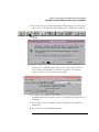
1 Select the Tools icon from the menu bar.
2 Select the Admin tab, select Self-Test, and read the text box before
selecting Yes.
3 In the Self Test window select the System tab, select the Master or
Expander Frame tab, and then select the module you want to test.
114
Chapter 7: Troubleshooting
To execute disaster recovery procedures
To execute disaster recovery procedures
CAUTION:
Read this section carefully before you attempt to reinstall the operating
system from the CD-ROM using this procedure. Everything on the hard
drive will be overwritten, including user configuration, data files, and
license passwords. To save your system’s license information, as well as
other system settings, refer to page 13. To reload, refer to page 15.
A batch process is used to autoload the software and then reboot the
instrument. The batch process waits for only a short time-out period for user
interaction to abort the process. Otherwise, the hard drive will be initialized,
the operating system will be uploaded, and the instrument will reboot.
The reinstallation process takes approximately one hour depending on the
speed of the attached CD-ROM.
1 If you have a 16702B, you will need to connect a keyboard to your
system in order to execute these procedures.
2 If required, follow the steps on page 13 to create a backup file of your
system settings and license passwords.
3 Insert the CD-ROM containing the instrument operating software into
the CD-ROM drive. Allow a couple of moments for the media to settle
after inserting the media.
4 If the LAN cable is connected, disconnect it from the instrument.
5 If needed, turn on the system and initiate the monitor selection mode.
Follow the instructions beginning with step one on page 19 if you have
a 16700B or page 21 if you have a 16702B. Otherwise, proceed to the
next step.
6 Turn on the instrument and repeatedly press the [ESC] key on the
keyboard to terminate the boot process. When the boot process is
terminated, a prompt will be displayed.
Main Menu: Enter command >
a Press: <Enter>
b Type: SEA <Enter>
The instrument will search for all viable boot devices on the bus, including the
115
Chapter 7: Troubleshooting
To execute disaster recovery procedures
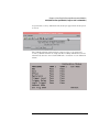
CD-ROM drive. The display will then show the boot devices:
Path Number
-----------P0
P1
Device Path
-----------SESCSI.6.0
SESCSI.1.0
Device Type
-----------------IBM
DNES-309170W
PLEXTOR CD-ROM PX-40TS
7 At the prompt:
Main Menu: Enter command >
Type: BO P1 <Enter>
8 At the prompt:
Interact with IPL (Y, N, Q) ?>
Type:
N <Enter>
9 After about 30 seconds you will see the message:
WARNING: The configuration information calls for a noninteractive installation.
Press <Return> within 10 seconds to cancel batch mode
installation:
10 To abort the reinstallation process at this point:
Press the [Return] key on the keyboard within 10 seconds. (If you do nothing
within the 10 second time-out, the reinstallation process will begin. The
instrument will completely reload the operating system software onto the hard
disk drive.)
11 Processor Support Packages, Auxiliary Software, and user files must be
installed manually once the operating system has been reinstalled.
12 Follow the steps on page 15 to reload system settings and license
passwords.
116
Index
Numerics
16517/18A logic analyzer module,
47, 48, 49, 50
16522A pattern generator module,
88, 89, 90, 91
16533/34A oscilloscope module, 72
(calibration), 72
(multicard), 81
(operational accuracy), 75
16557D logic analyzer module, 50,
51, 52, 53, 54
16701B expander frame, 37
16710/11/12A logic analyzer
module, 55, 56
16715/16/17A logic analyzer
module, 57, 58, 59, 60, 61
16718/19A logic analyzer module,
57, 58, 59, 60, 61
16720A pattern generator module,
92, 93, 94, 95
16740/41/42A logic analyzer
module, 57, 58, 59, 60, 61
16750/51/52A logic analyzer
module, 57, 58, 59, 60, 61
16753/54/55A logic analyzer
module, 62, 63, 64, 65, 66
16760A logic analyzer module, 67,
68, 69, 70
34-channel single-ended probe,
106
38-pin adapter cable,E5351A, 105
38-pin probe, E5346A, 104
B
backup system settings, 13
boot drive, removable, 31
disconnecting, 34
C
calibration, 16533/34A, 75
characteristics, 11
cleaning the instrument, 149
configuring
monitor for 16700B, 19
monitor for 16702B, 21
connecting
16701B expander frame, 37
external data drive, 26
keyboard, 18
LAN, 22
logic analyzer probe directly to
target, 102
monitor, 18
mouse, 18
multiple frames, 38
option 008, 26
option 009, 31
printer, 24
removable boot drive, 31
D
data drive, 26
differential probe, 107, 111
direct connection probing, 102
disaster recovery, 115
disconnecting
external data drive, 30
option 008, 30
option 009, 34
removable boot drive, 34
E
E5339A 38-pin low-voltage probe,
103
E5351A 38-pin adapter cable, 105
E5379A 100-pin differential probe,
107
E5382A single-ended flying lead
probe set, 110
E5386A half-channel adapter, 109
E5850A time correlation fixture,
112
expander frame, 37
external data drive
connecting, 26
disconnecting, 30
F
flying lead
general-purpose, 99
single-ended, 110
frames
expander, 37
multiple, 38
G
general-purpose probing, 99
H
half-channel adapter, 109
I
installation
disaster recovery, 115
measurement modules, 42
software, 34
instrument, cleaning the, 149
isolation adapter probing, 101
K
keyboard, 18
L
LAN, 22
license passwords, 13, 15
logic analyzer modules
16517/18A (2-card), 47
16517/18A (3-card), 48
16517/18A (4-card), 49
16517/18A (5-card), 50
16557D (1-card), 50
16557D (2-card), 51
16557D (3-card), 52
16557D (4-card), 53
117
Index
16557D (5-card), 54
16710/11/12A (1-card), 55
16710/11/12A (2-card), 56
16715/16/17A (1-card), 57
16715/16/17A (2-card), 58
16715/16/17A (3-card), 59
16715/16/17A (4-card), 60
16715/16/17A (5-card), 61
16718/19A (1-card), 57
16718/19A (2-card), 58
16718/19A (3-card), 59
16718/19A (4-card), 60
16718/19A (5-card), 61
16740/41/42A (1-card), 57
16740/41/42A (2-card), 58
16740/41/42A (3-card), 59
16740/41/42A (4-card), 60, 61
16750/51/52A (1-card), 57
16750/51/52A (2-card), 58
16750/51/52A (3-card), 59
16750/51/52A (4-card), 60, 61
16753/54/55A (1-card), 62
16753/54/55A (2-card), 63
16753/54/55A (3-card), 64
16753/54/55A (4-card), 65, 66
16760A (1-card), 67
16760A (2-card), 67
16760A (3-card), 68
16760A (4-card), 69
16760A (5-card), 70
low-voltage probe, 38-pin, 103
M
measurement modules
installing, removing, or replacing,
42
logic analyzer
16517/18A, 47, 48, 49, 50
16557D, 50, 51, 52, 53, 54
16710/11/12A, 55, 56
16715/16/17A, 57, 58, 59, 60,
61
118
167150/51/52A, 57, 58, 59
16718/19A, 57, 58, 59, 60, 61
16740/41/42A, 57, 58, 59, 60,
61
16750/51/52A, 60, 61
16753/54/55A, 62, 63, 64, 65,
66
16760A, 67, 68, 69, 70
oscilloscope
16533/34A, 72, 81
16533/34A (calibration), 72
16533/34A (operational
accuracy), 75
pattern generator
16522A, 88, 89, 90, 91
16720A, 92, 93, 94, 95
MICTOR, 38-pin, 103, 104
monitor
changing/configuring, 22
configuring for 16700B, 19
configuring for 16702B, 21
connecting, 18
mouse, 18
multi-card modules, 42, 55, 56,
57, 58, 59, 60, 61, 63, 64, 65,
66
multiple frames, 38
O
operational accuracy calibration,
16533/34A, 75
option 008, 26
option 009, 31
disconnecting, 34
oscilloscope module
16533/34A, 72
calibration, 72
multicard module, 81
operational accuracy, 75
P
passwords, 13, 15
pattern generator modules
16522A (1-card), 88
16522A (2-card), 89
16522A (3-card), 89
16522A (4-card), 90
16522A (5-card), 91
16720A (1-card), 92
16720A (2-card), 92
16720A (3-card), 93
16720A (4-card), 94
16720A (5-card), 95
printer, connecting, 24
probe leads, 99
probing
100-pin differential probe, 107
100-pin single-ended probe
(16760A), 106
38-pin adapter cable, 105
38-pin low-voltage, 103
38-pin probe, 104
38-pin single-ended probe, 108
direct connection, 102
E5339A, 103
E5346A 38-pin, 104
E5351A, 105
E5378A single-ended probe, 106
E5379A, 107
E5382A single-ended flying lead,
110
E5386A half-channel adapter,
109
E5387A differential soft touch,
111
E5390A single-ended soft touch,
111
general-purpose, 99
half-channel adapter, 109
isolation adapter, 101
single-ended flying lead, 110
single-ended probe, 38-pin, 108
soft touch, 111
Index
R
recovering, 115
reinstallation, 115
removable boot drive
connecting, 31
disconnecting, 34
removing
measurement modules, 42
replacing
measurement modules, 42
restoring, 115
run self-tests, 114
S
self-tests, 114
single-ended probe, 106, 111
soft touch probes, 111
software
installation, 34
reinstalling, 115
software requirements
logic analyzer modules, 46
pattern generator modules, 88
specifications, 11
system settings
backup, 13
reloading, 15
T
tests, self, 114
time correlation, 112
troubleshooting, 114
W
waveforms, 112
119
120
s1
Manufacturer’s Name:
Manufacturer’s Address:
DECLARATION OF CONFORMITY
According to ISO/IEC Guide 22 and CEN/CENELEC EN 45014
Agilent Technologies, Inc.
1900 Garden of the Gods Road
Colorado Springs, Colorado
80907 U.S.A.
Declares, that the product
Product Name:
Digitizing Oscilloscope Module
Model Number:
16517A and 16518A
Product Options:
This declaration covers all options of the above product(s).
Conforms with the following product stardands:
EMC
Standard
CISPR 11:1990 / EN 55011:1991
IEC 555-2:1982 + A1:1985 / EN 60555-2:1987
IEC 555-3:1982 + A1:1990 / EN 60555-3:1987 + A1:1991
IEC 801-2:1991 / EN 50082-1:1992
IEC 801-3:1984 / EN 50082-1:1992
IEC 801-4:1988 / EN 50082-1:1992
Limit
Group 1, Class A
4 kV CD, 8 kV AD
3 V/m, {1kHz 80% AM, 27-1000 MHz}
0.5 kV Sig. Lines, 1 kV Power Lines
Safety IEC 1010-1:1990+A1 / EN 61010-1:1993
UL 3111
CSA-C22.2 No. 1010.1:1993
Additional Information:
The product herewith complies with the requirements of the Low Voltage Directive 73/23/EEC and the EMC Directive 89/336/EEC
(including 93/68/EEC) and carries the CE-marking accordingly (European Union).
The product was tested in a typical configuration with Agilent Technologies test systems.
Date: 10/03/96
Name
John Strathman / Quality Manager
For further information, please contact your local Agilent Technologies sales office, agent or distributor.
Product Regulations
EMC
This Product meets the requirements of the European
Communities (EC) EMC Directive 89/336/EEC.
Emissions EN55011/CISPR 11 (ISM, Group 1, Class A
equipment)
Immunity EN50082-1
IEC 555-2
IEC 555-3
IEC 801-2 (ESD) 8kV AD
IEC 801-3 (Rad.) 3V/m1
IEC 801-4 (EFT) 1kV
Performance Codes:
Performance Code1
1
1
2
1
1
1 Pass - Normal operation, no effect.
2 Pass - Temporary degradation, self recoverable.
3 Pass - Temporary degradation, operator
intervention required.
4 Fail - Not recoverable, component damage.
Safety
IEC 348:1978 / HD 401 S1:1981
UL 1244
CSA-C22.2 No. 231 (Series M-89)
Sound Pressure Level
N/A
Regulatory Information for Canada
ICES/NMB-001
This ISM device complies with Canadian ICES-001.
Cet appareil ISM est confomre à la norme NMB-001 du Canada.
Regulatory Information for Australia/New Zealand
This ISM device complies with Australian/New Zealand AS/NZS 2064.1
Definitions:
Installation category (overvoltage category) I: Signal level, special equipment or
parts of equipment, telecommunication, electronic etc., with smaller transient
overvoltages than installation (overvoltage category) II.
Installation category (overvoltage category) II: Local level, appliances, portable
equipment etc., with smaller transient overvoltages than installation category III.
Environmental
Conditions
Indoor use only.
Altitude up to 3000 m. (10,000 ft.)
Temperature
Instrument - 0 degrees C to 50 degrees C (32 degrees F to 122 degrees F)
Disk Media - 10 degrees C to 40 degrees C (50 degrees F to 104 degrees F
Probes/cables - 0 degrees C to 65 degrees C (32 degrees F to 149 degrees F)
Humidity
Relative humidity 8 to 80% at 40 degrees C (104 degrees F)
Power
(From host frame.)
s1
Manufacturer’s Name:
Manufacturer’s Address:
DECLARATION OF CONFORMITY
According to ISO/IEC Guide 22 and CEN/CENELEC EN 45014
Agilent Technologies, Inc.
1900 Garden of the Gods Road
Colorado Springs, Colorado
80907 U.S.A.
Declares, that the product
Product Name:
Pattern Generator Module
Model Number:
16522A
Product Options:
This declaration covers all options of the above product(s).
Conforms with the following product stardands:
EMC
Standard
CISPR 11:1990 / EN 55011:1991
IEC 555-2:1982 + A1:1985 / EN 60555-2:1987
IEC 555-3:1982 + A1:1990 / EN 60555-3:1987 + A1:1991
IEC 801-2:1991 / EN 50082-1:1992
IEC 801-3:1984 / EN 50082-1:1992
IEC 801-4:1988 / EN 50082-1:1992
Limit
Group 1, Class A
4 kV CD, 8 kV AD
3 V/m, {1kHz 80% AM, 27-1000 MHz}
0.5 kV Sig. Lines, 1 kV Power Lines
Safety IEC 1010-1:1990+A1 / EN 61010-1:1993
UL 3111
CSA-C22.2 No. 1010.1:1993
Additional Information:
The product herewith complies with the requirements of the Low Voltage Directive 73/23/EEC and the EMC Directive 89/336/EEC
(including 93/68/EEC) and carries the CE-marking accordingly (European Union).
The product was tested in a typical configuration with Agilent Technologies test systems.
Date: 4/03/95
Name
John Strathman / Quality Manager
For further information, please contact your local Agilent Technologies sales office, agent or distributor.
Product Regulations
EMC
This Product meets the requirements of the European
Communities (EC) EMC Directive 89/336/EEC.
Emissions EN55011/CISPR 11 (ISM, Group 1, Class A
equipment)
Immunity EN50082-1
IEC 555-2
IEC 555-3
IEC 801-2 (ESD) 8kV AD
IEC 801-3 (Rad.) 3V/m
IEC 801-4 (EFT) 1kV
Performance Codes1:
Code1
1
1
1
1
1
1 Pass - Normal operation, no effect.
2 Pass - Temporary degradation, self recoverable.
3 Pass - Temporary degradation, operator
intervention required.
4 Fail - Not recoverable, component damage.
Safety
IEC 1010-1:1990+A1 / EN 61010-1: 1993
UL 3111
CSA-C22.2 No. 1010.1:1993
Sound Pressure Level
N/A
Regulatory Information for Canada
ICES/NMB-001
This ISM device complies with Canadian ICES-001.
Cet appareil ISM est confomre à la norme NMB-001 du Canada.
Regulatory Information for Australia/New Zealand
This ISM device complies with Australian/New Zealand AS/NZS 2064.1
Definitions:
Installation category (overvoltage category) I: Signal level, special equipment or
parts of equipment, telecommunication, electronic etc., with smaller transient
overvoltages than installation (overvoltage category) II.
Installation category (overvoltage category) II: Local level, appliances, portable
equipment etc., with smaller transient overvoltages than installation category III.
Environmental
Conditions
Indoor use only.
Altitude up to 3000 m. (10,000 ft.)
Temperature
Instrument - 0 degrees C to 50 degrees C (32 degrees F to 122 degrees F)
Disk Media - 10 degrees C to 40 degrees C (50 degrees F to 104 degrees F
Probes/cables - 0 degrees C to 65 degrees C (32 degrees F to 149 degrees F)
Humidity
Relative humidity 8 to 80% at 40 degrees C (104 degrees F)
Power
(From host frame.)
s1
Manufacturer’s Name:
Manufacturer’s Address:
DECLARATION OF CONFORMITY
According to ISO/IEC Guide 22 and CEN/CENELEC EN 45014
Agilent Technologies, Inc.
1900 Garden of the Gods Road
Colorado Springs, Colorado
80907 U.S.A.
Declares, that the product
Product Name:
Digitizing Oscilloscope Module
Model Number:
16533A and 16534A
Product Options:
This declaration covers all options of the above product(s).
Conforms with the following product stardands:
EMC
Standard
CISPR 11:1990 / EN 55011:1991
IEC 555-2:1982 + A1:1985 / EN 60555-2:1987
IEC 555-3:1982 + A1:1990 / EN 60555-3:1987 + A1:1991
IEC 801-2:1991 / EN 50082-1:1992
IEC 801-3:1984 / EN 50082-1:1992
IEC 801-4:1988 / EN 50082-1:1992
Limit
Group 1, Class A
4 kV CD, 8 kV AD
3 V/m, {1kHz 80% AM, 27-1000 MHz}
0.5 kV Sig. Lines, 1 kV Power Lines
Safety IEC 1010-1:1990+A1 / EN 61010-1:1993
UL 3111
CSA-C22.2 No. 1010.1:1993
Additional Information:
The product herewith complies with the requirements of the Low Voltage Directive 73/23/EEC and the EMC Directive 89/336/EEC
(including 93/68/ECC) and carries the CE-marking accordingly (European Union).
The product was tested in a typical configuration with Agilent Technologies test systems.
Date: 4/03/95
Name
John Strathman / Quality Manager
For further information, please contact your local Agilent Technologies sales office, agent or distributor.
Product Regulations
EMC
This Product meets the requirements of the European
Communities (EC) EMC Directive 89/336/EEC.
Emissions EN55011/CISPR 11 (ISM, Group 1, Class A
equipment)
Immunity EN50082-1
IEC 555-2
IEC 555-3
IEC 801-2 (ESD) 8kV AD
IEC 801-3 (Rad.) 3V/m
IEC 801-4 (EFT) 1kV
Performance Codes1:
Code1
1
1
1
1
1
1 Pass - Normal operation, no effect.
2 Pass - Temporary degradation, self recoverable.
3 Pass - Temporary degradation, operator
intervention required.
4 Fail - Not recoverable, component damage.
Safety
IEC 1010-1:1990+A1 / EN 61010-1: 1993
UL 3111
CSA-C22.2 No. 1010.1:1993
Sound Pressure Level
N/A
Regulatory Information for Canada
ICES/NMB-001
This ISM device complies with Canadian ICES-001.
Cet appareil ISM est confomre à la norme NMB-001 du Canada.
Regulatory Information for Australia/New Zealand
This ISM device complies with Australian/New Zealand AS/NZS 2064.1
Definitions:
Installation category (overvoltage category) I: Signal level, special equipment or
parts of equipment, telecommunication, electronic etc., with smaller transient
overvoltages than installation (overvoltage category) II.
Installation category (overvoltage category) II: Local level, appliances, portable
equipment etc., with smaller transient overvoltages than installation category III.
Environmental
Conditions
Indoor use only.
Altitude up to 3000 m. (10,000 ft.)
Temperature
Instrument - 0 degrees C to 50 degrees C (32 degrees F to 122 degrees F)
Disk Media - 10 degrees C to 40 degrees C (50 degrees F to 104 degrees F
Probes/cables - 0 degrees C to 65 degrees C (32 degrees F to 149 degrees F)
Humidity
Relative humidity 8 to 80% at 40 degrees C (104 degrees F)
Power
(From host frame.)
s1
Manufacturer’s Name:
Manufacturer’s Address:
DECLARATION OF CONFORMITY
According to ISO/IEC Guide 22 and CEN/CENELEC EN 45014
Agilent Technologies, Inc.
1900 Garden of the Gods Road
Colorado Springs, Colorado
80907 U.S.A.
Declares, that the product
Product Name:
Logic Analyzer Module
Model Number:
16557D
Product Options:
This declaration covers all options of the above product(s).
Conforms with the following product stardands:
EMC
Standard
CISPR 11:1990 / EN 55011:1991
IEC 555-2:1982 + A1:1985 / EN 60555-2:1987
IEC 555-3:1982 + A1:1990 / EN 60555-3:1987 + A1:1991
IEC 801-2:1991 / EN 50082-1:1992
IEC 801-3:1984 / EN 50082-1:1992
IEC 801-4:1988 / EN 50082-1:1992
Limit
Group 1, Class A
4 kV CD, 8 kV AD
3 V/m, {1kHz 80% AM, 27-1000 MHz}
0.5 kV Sig. Lines, 1 kV Power Lines
Safety IEC 1010-1:1990+A1 / EN 61010-1:1993
UL 3111
CSA-C22.2 No. 1010.1:1993
Additional Information:
The product herewith complies with the requirements of the Low Voltage Directive 73/23/EEC and the EMC Directive 89/336/EEC
(including 93/68/EEC) and carries the CE-marking accordingly (European Union).
The product was tested in a typical configuration with Agilent Technologies test systems.
Date: 7/02/97
Name
John Strathman / Quality Manager
For further information, please contact your local Agilent Technologies sales office, agent or distributor.
Product Regulations
EMC
This Product meets the requirements of the European
Communities (EC) EMC Directive 89/336/EEC.
Emissions EN55011/CISPR 11 (ISM, Group 1, Class A
equipment)
IEC 555-2 and IEC 555-3
Immunity EN50082-1
IEC 801-2 (ESD) 8kV AD
IEC 801-3 (Rad.) 3V/m
IEC 801-4 (EFT) 1kV
Performance Codes1:
Code1
1
1
1
1 Pass - Normal operation, no effect.
2 Pass - Temporary degradation, self recoverable.
3 Pass - Temporary degradation, operator
intervention required.
4 Fail - Not recoverable, component damage.
Safety
IEC 1010-1:1990+A1 / EN 61010-1: 1993
UL 3111
CSA-C22.2 No. 1010.1:1993
Sound Pressure Level
N/A
Regulatory Information for Canada
ICES/NMB-001
This ISM device complies with Canadian ICES-001.
Cet appareil ISM est confomre à la norme NMB-001 du Canada.
Regulatory Information for Australia/New Zealand
This ISM device complies with Australian/New Zealand AS/NZS 2064.1
Definitions:
Installation category (overvoltage category) I: Signal level, special equipment or
parts of equipment, telecommunication, electronic etc., with smaller transient
overvoltages than installation (overvoltage category) II.
Installation category (overvoltage category) II: Local level, appliances, portable
equipment etc., with smaller transient overvoltages than installation category III.
Environmental
Conditions
Indoor use only.
Altitude up to 3000 m. (10,000 ft.)
Temperature
Instrument - 0 degrees C to 50 degrees C (32 degrees F to 122 degrees F)
Disk Media - 10 degrees C to 40 degrees C (50 degrees F to 104 degrees F
Probes/cables - 0 degrees C to 65 degrees C (32 degrees F to 149 degrees F)
Humidity
Relative humidity 8 to 80% at 40 degrees C (104 degrees F)
Power
(From host frame.)
s1
Manufacturer’s Name:
Manufacturer’s Address:
DECLARATION OF CONFORMITY
According to ISO/IEC Guide 22 and CEN/CENELEC EN 45014
Agilent Technologies, Inc.
1900 Garden of the Gods Road
Colorado Springs, Colorado
80907 U.S.A.
Declares, that the product
Product Name:
Logic Analysis System Mainframe
Model Number:
16700B, 16701B and 16702B
Product Options:
This declaration covers all options of the above product(s).
Conforms with the following product stardands:
EMC
Standard
IEC 61326-1:1997+A1:1998 / EN 61326-1:1997+A1:1998
CCISPR 11:1990/EN 55011:1991
IEC 61000-4-2:1995+A1:1998 / EN 61000-4-2:1995
IEC 61000-4-3:1995/EN 61000-4-3:1995
IEC 61000-4-4:1995/EN 61000-4-4:1995
IEC 61000-4-5:1995 / EN 61000-4-5:1995
IEC 61000-4-6:1996/EN 61000-4-6:1996
IEC 61000-4-11:1994 / EN 61000-4-11:1994
Canada: ICES-001:1998
Australia/New Zealand: AS/NZS 2064.1
Limit
Group 1 Class A[1, 2]
4kV CD, 8kV AD
3V/m, 80-1000 MHz
0.5kV signal lines, 1kV power lines
0.5 kV line-line, 1 kV line-ground
3V, 0.15-80 MHz
1 cycle, 100%
Safety IEC 61010-1:1990+A1:1992+A2:1995 / EN 61010-1:1993+A2:1995
Canada: CSA C22.2 No. 1010.1:1992
Additional Information:
The product herewith complies with the requirements of the Low Voltage Directive 73/23/EEC and the EMC Directive 89/336/EEC
(including 93/68/EEC) and carries the CE-marking accordingly (European Union).
[1]
[2]
The product was tested in a typical configuration with Agilent Technologies test systems.
The product meets CISPR requirements using “type test” specified in IEC 61326-1 edition 1.1, section 3.1..
Date: 02/11/2002
Name
Ken Wyatt / Product Regulations Manager
For further information, please contact your local Agilent Technologies sales office, agent or distributor.
Product Regulations
IEC 61326-1:1997+A1:1998 / EN 61326-1:1997+A1:1998
Performance Criteria1
CISPR 11:1990 / EN 55011:1991
IEC 61000-4-2:1995+A1:1998 / EN 61000-4-2:1995
IEC 61000-4-3:1995 / EN 61000-4-3:1995
A
IEC 61000-4-4:1995 / EN 61000-4-4:1995
A
IEC 61000-4-5:1995 / EN 61000-4-5:1995
A
IEC 61000-4-6:1996 / EN 61000-4-6:1996
A
IEC 61000-4-11:1994 / EN 61000-4-11:1994
Canada: ICES-001:1998
Australia/New Zealand: AS/NZS 2064.1
Safety
IEC 61010-1:1990+A1:1992+A2:1995 / EN 61010-1:1993+A2:1995
Canada: CSA C22.2 No. 1010.1:1992
Additional Information
The product herewith complies with the requirements of the Low Voltage Directive 73/23/EEC and the EMC Directive
89/336/EEC (including 93/68/EEC) and carries the CE Marking accordingly (European Union).
1
Performance Criteria:
A Pass - Normal operation, no effect.
B Pass - Temporary degradation, self recoverable.
C Pass - Temporary degradation, operator intervention required.
D Fail - Not recoverable, component damage.
Sound Pressure Level
Less than 60 dBA
Regulatory Information for Canada
EMC
ICES/NMB-001
This ISM device complies with Canadian ICES-001.
Cet appareil ISM est confomre à la norme NMB-001 du Canada.
Regulatory Information for Australia/New Zealand
This ISM device complies with Australian/New Zealand AS/NZS 2064.1
Definitions:
Installation category (overvoltage category) I: Signal level, special equipment or
parts of equipment, telecommunication, electronic etc., with smaller transient
overvoltages than installation (overvoltage category) II.
Installation category (overvoltage category) II: Local level, appliances, portable
equipment etc., with smaller transient overvoltages than installation category III.
Environmental
Conditions
Indoor use only.
Altitude up to 3000 m. (10,000 ft.)
Temperature
Instrument - 0 degrees C to 50 degrees C (32 degrees F to 122 degrees F)
Disk Media - 10 degrees C to 40 degrees C (50 degrees F to 104 degrees F
Probes/cables - 0 degrees C to 65 degrees C (32 degrees F to 149 degrees F)
Humidity
Relative humidity 8 to 80% at 40 degrees C (104 degrees F)
Power
(From host frame.)
s1
Manufacturer’s Name:
Manufacturer’s Address:
DECLARATION OF CONFORMITY
According to ISO/IEC Guide 22 and CEN/CENELEC EN 45014
Agilent Technologies, Inc.
1900 Garden of the Gods Road
Colorado Springs, Colorado
80907 U.S.A.
Declares, that the product
Product Name:
Logic Analyzer Module
Model Number:
16710A, 16711A and 16712A
Product Options:
This declaration covers all options of the above product(s).
Conforms with the following product stardands:
EMC
Standard
CISPR 11:1990 / EN 55011:1991
IEC 555-2:1982 + A1:1985 / EN 60555-2:1987
IEC 555-3:1982 + A1:1990 / EN 60555-3:1987 + A1:1991
IEC 801-2:1991 / EN 50082-1:1992
IEC 801-3:1984 / EN 50082-1:1992
IEC 801-4:1988 / EN 50082-1:1992
Safety IEC 1010-1:1990+A1 / EN 61010-1:1993
UL 3111
CSA-C22.2 No. 1010.1:1993
Limit
Group 1, Class A
4 kV CD, 8 kV AD
3 V/m, {1kHz 80% AM, 27-1000 MHz}
0.5 kV Sig. Lines, 1 kV Power Line
Additional Information:
The product herewith complies with the requirements of the Low Voltage Directive 73/23/EEC and the EMC Directive 89/336/EEC
(including 93/68/EEC) and carries the CE-marking accordingly (European Union).
The product was tested in a typical configuration with Agilent Technologies test systems.
Date: 09/01/98
Name
Ken Wyatt / Product Regulations Manager
For further information, please contact your local Agilent Technologies sales office, agent or distributor.
Product Regulations
EMC
This Product meets the requirements of the European
Communities (EC) EMC Directive 89/336/EEC.
Emissions EN55011/CISPR 11 (ISM, Group 1, Class A
equipment),
IEC 555-2 and IEC 555-3
Immunity EN50082-1
Code1
IEC 801-2 (ESD) 8kV AD
2
IEC 801-3 (Rad.) 3V/m
1
IEC 801-4 (EFT) 1kV
1
Performance Codes1:
1 Pass - Normal operation, no effect.
2 Pass - Temporary degradation, self recoverable.
3 Pass - Temporary degradation, operator intervention
required.
4 Fail - Not recoverable, component damage.
Safety
IEC 1010-1: 1990+A1 / EN 61010-1: 1993
UL 3111
CSA-C22.2 No.1010.1:1993
Sound Pressure Level
N/A
Regulatory Information for Canada
ICES/NMB-001
This ISM device complies with Canadian ICES-001.
Cet appareil ISM est confomre à la norme NMB-001 du Canada.
Regulatory Information for Australia/New Zealand
This ISM device complies with Australian/New Zealand AS/NZS 2064.1
Definitions:
Installation category (overvoltage category) I: Signal level, special equipment or
parts of equipment, telecommunication, electronic etc., with smaller transient
overvoltages than installation (overvoltage category) II.
Installation category (overvoltage category) II: Local level, appliances, portable
equipment etc., with smaller transient overvoltages than installation category III.
Environmental
Conditions
Indoor use only.
Altitude up to 3000 m. (10,000 ft.)
Temperature
Instrument - 0 degrees C to 50 degrees C (32 degrees F to 122 degrees F)
Disk Media - 10 degrees C to 40 degrees C (50 degrees F to 104 degrees F
Probes/cables - 0 degrees C to 65 degrees C (32 degrees F to 149 degrees F)
Humidity
Relative humidity 8 to 80% at 40 degrees C (104 degrees F)
Power
(From host frame.)
s1
Manufacturer’s Name:
Manufacturer’s Address:
DECLARATION OF CONFORMITY
According to ISO/IEC Guide 22 and CEN/CENELEC EN 45014
Agilent Technologies, Inc.
1900 Garden of the Gods Road
Colorado Springs, Colorado
80907 U.S.A.
Declares, that the product
Product Name:
Logic Analyzer Module
Model Number:
16715A, 16716A and 16717A
Product Options:
This declaration covers all options of the above product(s).
Conforms with the following product stardands:
EMC
Standard
CISPR 11:1990 / EN 55011:1991
IEC 555-2:1982 + A1:1985 / EN 60555-2:1987
IEC 555-3:1982 + A1:1990 / EN 60555-3:1987 + A1:1991
IEC 801-2:1991 / EN 50082-1:1992
IEC 801-3:1984 / EN 50082-1:1992
IEC 801-4:1988 / EN 50082-1:1992
Safety IEC 1010-1:1990+A1 / EN 61010-1:1993
UL 3111
CSA-C22.2 No. 1010.1:1993
Limit
Group 1, Class A
4 kV CD, 8 kV AD
3 V/m, {1kHz 80% AM, 27-1000 MHz}
0.5 kV Sig. Lines, 1 kV Power Line
Additional Information:
The product herewith complies with the requirements of the Low Voltage Directive 73/23/EEC and the EMC Directive 89/336/EEC
(including 93/68/EEC) and carries the CE-marking accordingly (European Union).
The product was tested in a typical configuration with Agilent Technologies test systems.
Date: 03/19/99
Name
Ken Wyatt / Product Regulations Manager
For further information, please contact your local Agilent Technologies sales office, agent or distributor.
Product Regulations
EMC
This Product meets the requirements of the European
Communities (EC) EMC Directive 89/336/EEC.
Emissions EN55011/CISPR 11 (ISM, Group 1, Class A
equipment),
IEC 555-2 and IEC 555-3
Immunity EN50082-1
Code1
IEC 801-2 (ESD) 8kV AD
2
IEC 801-3 (Rad.) 3V/m
1
IEC 801-4 (EFT) 1kV
1
Performance Codes1:
1 Pass - Normal operation, no effect.
2 Pass - Temporary degradation, self recoverable.
3 Pass - Temporary degradation, operator intervention
required.
4 Fail - Not recoverable, component damage.
Safety
IEC 1010-1: 1990+A1 / EN 61010-1: 1993
UL 3111
CSA-C22.2 No.1010.1:1993
Sound Pressure Level
N/A
Regulatory Information for Canada
ICES/NMB-001
This ISM device complies with Canadian ICES-001.
Cet appareil ISM est confomre à la norme NMB-001 du Canada.
Regulatory Information for Australia/New Zealand
This ISM device complies with Australian/New Zealand AS/NZS 2064.1
Definitions:
Installation category (overvoltage category) I: Signal level, special equipment or
parts of equipment, telecommunication, electronic etc., with smaller transient
overvoltages than installation (overvoltage category) II.
Installation category (overvoltage category) II: Local level, appliances, portable
equipment etc., with smaller transient overvoltages than installation category III.
Environmental
Conditions
Indoor use only.
Altitude up to 3000 m. (10,000 ft.)
Temperature
Instrument - 0 degrees C to 50 degrees C (32 degrees F to 122 degrees F)
Disk Media - 10 degrees C to 40 degrees C (50 degrees F to 104 degrees F
Probes/cables - 0 degrees C to 65 degrees C (32 degrees F to 149 degrees F)
Humidity
Relative humidity 8 to 80% at 40 degrees C (104 degrees F)
Power
(From host frame.)
s1
Manufacturer’s Name:
Manufacturer’s Address:
DECLARATION OF CONFORMITY
According to ISO/IEC Guide 22 and CEN/CENELEC EN 45014
Agilent Technologies, Inc.
1900 Garden of the Gods Road
Colorado Springs, Colorado
80907 U.S.A.
Declares, that the product
Product Name:
Logic Analysis Module
Model Number:
16718A and 16719A
Product Options:
This declaration covers all options of the above product(s).
Conforms with the following product stardands:
EMC
Standard
CISPR 11:1990 / EN 55011:1991
IEC 555-2:1982 + A1:1985 / EN 60555-2:1987
IEC 555-3:1982 + A1:1990 / EN 60555-3:1987 + A1:1991
IEC 801-2:1991 / EN 50082-1:1992
IEC 801-3:1984 / EN 50082-1:1992
IEC 801-4:1988 / EN 50082-1:1992
Safety IEC 1010-1:1990+A1 / EN 61010-1:1993
UL 3111
CSA-C22.2 No. 1010.1:1993
Limit
Group 1, Class A
4 kV CD, 8 kV AD
3 V/m, {1kHz 80% AM, 27-1000 MHz}
0.5 kV Sig. Lines, 1 kV Power Line
Additional Information:
The product herewith complies with the requirements of the Low Voltage Directive 73/23/EEC and the EMC Directive 89/336/EEC
(including 93/68/EEC) and carries the CE-marking accordingly (European Union).
The product was tested in a typical configuration with Agilent Technologies test systems.
Date: 06/16/99
Name
Ken Wyatt / Product Regulations Manager
For further information, please contact your local Agilent Technologies sales office, agent or distributor.
Product Regulations
EMC
This Product meets the requirements of the European
Communities (EC) EMC Directive 89/336/EEC.
Emissions EN55011/CISPR 11 (ISM, Group 1, Class A
equipment),
IEC 555-2 and IEC 555-3
Immunity EN50082-1
Code1
IEC 801-2 (ESD) 8kV AD
2
IEC 801-3 (Rad.) 3V/m
1
IEC 801-4 (EFT) 1kV
1
Performance Codes1:
1 Pass - Normal operation, no effect.
2 Pass - Temporary degradation, self recoverable.
3 Pass - Temporary degradation, operator intervention
required.
4 Fail - Not recoverable, component damage.
Safety
IEC 1010-1: 1990+A1 / EN 61010-1: 1993
UL 3111
CSA-C22.2 No.1010.1:1993
Sound Pressure Level
N/A
Regulatory Information for Canada
ICES/NMB-001
This ISM device complies with Canadian ICES-001.
Cet appareil ISM est confomre à la norme NMB-001 du Canada.
Regulatory Information for Australia/New Zealand
This ISM device complies with Australian/New Zealand AS/NZS 2064.1
Definitions:
Installation category (overvoltage category) I: Signal level, special equipment or
parts of equipment, telecommunication, electronic etc., with smaller transient
overvoltages than installation (overvoltage category) II.
Installation category (overvoltage category) II: Local level, appliances, portable
equipment etc., with smaller transient overvoltages than installation category III.
Environmental
Conditions
Indoor use only.
Altitude up to 3000 m. (10,000 ft.)
Temperature
Instrument - 0 degrees C to 50 degrees C (32 degrees F to 122 degrees F)
Disk Media - 10 degrees C to 40 degrees C (50 degrees F to 104 degrees F
Probes/cables - 0 degrees C to 65 degrees C (32 degrees F to 149 degrees F)
Humidity
Relative humidity 8 to 80% at 40 degrees C (104 degrees F)
Power
(From host frame.)
s1
Manufacturer’s Name:
Manufacturer’s Address:
DECLARATION OF CONFORMITY
According to ISO/IEC Guide 22 and CEN/CENELEC EN 45014
Agilent Technologies, Inc.
1900 Garden of the Gods Road
Colorado Springs, Colorado
80907 U.S.A.
Declares, that the product
Product Name:
Pattern Generator Module
Model Number:
16720A
Product Options:
This declaration covers all options of the above product(s).
Conforms with the following product stardands:
EMC
Standard
Limit
IEC 61326-1:1997+A1:1998 / EN 61326-1:1997+A1:1998
CISPR 11:1990 / EN 55011:1991
Group 1 Class A [1]
IEC 61000-4-2:1995+A1:1998 / EN 61000-4-2:1995
(ESD 4kV CD, 8kV AD)
IEC 61000-4-3:1995 / EN 61000-4-3:1995
(3V/m 80% AM)
IEC 61000-4-4:1995 / EN 61000-4-4:1995
(0.5kV line-line, 1kV line-earth)
IEC 61000-4-5:1995 / EN 61000-4-5:1995
(0.5kV line-line, 1kV line-ground)
IEC 61000-4-6:1996 / EN 61000-4-6:1996
(3V 80% AM, power line)
IEC 61000-4-11:1994/EN 61000-4-11:1994
(1 cycle, 100%)
Australia/New Zealand: AS/NZS 2064.1
Safety IEC 61010-1:1990+A1:1992+A2:1995 / EN 61010-1:1994+A2:1995
Canada: CSA C22.2 No. 1010.1:1992
USA: UL 3111-1:1994
Additional Information:
The product herewith complies with the requirements of the Low Voltage Directive 73/23/EEC and the EMC Directive 89/336/EEC
(including 93/68/EEC) and carries the CE-marking accordingly (European Union).
[1]
The product was tested in a typical configuration with Agilent Technologies test systems.
Date: 02/10/2000
Name
Ken Wyatt / Product Regulations Manager
For further information, please contact your local Agilent Technologies sales office, agent or distributor.
Product Regulations
Performance Criteria[2]
IEC 61326-1:1997+A1:1998 / EN 61326-1:1997+A1:1998
CISPR 11:1990 / EN 55011:1991
IEC 61000-4-2:1995+A1:1998/EN 61000-4-2:1995
A
IEC 61000-4-3:1995 / EN 61000-4-3:1995
A
IEC 61000-4-4:1995 / EN 61000-4-4:1995
A
IEC 61000-4-5:1995 / EN 61000-4-5:1995
A
IEC 61000-4-6:1996 / EN 61000-4-6:1996
A
IEC 61000-4-11:1994 / EN 61000-4-11:1994
A
Canada: ICES-001:1998
Safety
IEC 61010-1:1990+A1:1992+A2:1995 / EN 61010-1:1994+A2:1995
Canada: CSA C22.2 No. 1010.1:1992
Additional Information
The product herewith complies with the requirements of the Low Voltage Directive 73/23/EEC and the EMC Directive
89/336/EEC (including 93/68/EEC) and carries the CE Marking accordingly (European Union).
[2]
Performance Criteria:
A Pass - Normal operation, no effect.
B Pass - Temporary degradation, self recoverable.
C Pass - Temporary degradation, operator intervention required.
D Fail - Not recoverable, component damage.
Sound Pressure Level
N/A
Regulatory Information for Canada
EMC
ICES/NMB-001:1998
This ISM device complies with Canadian ICES-001.
Cet appareil ISM est confomre à la norme NMB-001 du Canada.
Regulatory Information for Australia/New Zealand
This ISM device complies with Australian/New Zealand AS/NZS 2064.1
Definitions:
Installation category (overvoltage category) I: Signal level, special equipment or
parts of equipment, telecommunication, electronic etc., with smaller transient
overvoltages than installation (overvoltage category) II.
Installation category (overvoltage category) II: Local level, appliances, portable
equipment etc., with smaller transient overvoltages than installation category III.
Environmental
Conditions
Indoor use only.
Altitude up to 3000 m. (10,000 ft.)
Temperature
Instrument - 0 degrees C to 50 degrees C (32 degrees F to 122 degrees F)
Disk Media - 10 degrees C to 40 degrees C (50 degrees F to 104 degrees F
Probes/cables - 0 degrees C to 65 degrees C (32 degrees F to 149 degrees F)
Humidity
Relative humidity 8 to 80% at 40 degrees C (104 degrees F)
Power
(From host frame.)
s1
Manufacturer’s Name:
Manufacturer’s Address:
DECLARATION OF CONFORMITY
According to ISO/IEC Guide 22 and CEN/CENELEC EN 45014
Agilent Technologies, Inc.
1900 Garden of the Gods Road
Colorado Springs, Colorado
80907 U.S.A.
Declares, that the product
Product Name:
Logic Analyzer Module
Model Number:
16740A, 16741A and 16742A
Product Options:
This declaration covers all options of the above product(s).
Conforms with the following product stardands:
EMC
Standard
IEC 61326-1:1997+A1:1998 / EN 61326-1:1997+A1:1998
CCISPR 11:1990/EN 55011:1991
IEC 61000-4-2:1995+A1:1998 / EN 61000-4-2:1995
IEC 61000-4-3:1995/EN 61000-4-3:1995
IEC 61000-4-4:1995/EN 61000-4-4:1995
IEC 61000-4-5:1995 / EN 61000-4-5:1995
IEC 61000-4-6:1996/EN 61000-4-6:1996
IEC 61000-4-11:1994 / EN 61000-4-11:1994
Canada: ICES-001:1998
Australia/New Zealand: AS/NZS 2064.1
Limit
Group 1 Class A[1]
4kV CD, 8kV AD
3V/m, 80-1000 MHz
0.5kV signal lines, 1kV power lines
0.5 kV line-line, 1 kV line-ground
3V, 0.15-80 MHz
1 cycle, 100%
Safety IEC 61010-1:1990+A1:1992+A2:1995 / EN 61010-1:1993+A2:1995
Canada: CSA C22.2 No. 1010.1:1992
Additional Information:
The product herewith complies with the requirements of the Low Voltage Directive 73/23/EEC and the EMC Directive 89/336/EEC
(including 93/68/EEC) and carries the CE-marking accordingly (European Union).
[1]
The product was tested in a typical configuration with Agilent Technologies test systems.
Date: 08/29/2001
Name
Ken Wyatt / Product Regulations Manager
For further information, please contact your local Agilent Technologies sales office, agent or distributor.
Product Regulations
IEC 61326-1:1997+A1:1998 / EN 61326-1:1997+A1:1998
Performance Criteria[2]
CISPR 11:1990 / EN 55011:1991
IEC 61000-4-2:1995+A1:1998 / EN 61000-4-2:1995
A
IEC 61000-4-3:1995 / EN 61000-4-3:1995
A
IEC 61000-4-4:1995 / EN 61000-4-4:1995
A
IEC 61000-4-5:1995 / EN 61000-4-5:1995
A
IEC 61000-4-6:1996 / EN 61000-4-6:1996
A
IEC 61000-4-11:1994 / EN 61000-4-11:1994
A
Canada: ICES-001:1998
Australia/New Zealand: AS/NZS 2064.1
Safety
IEC 61010-1:1990+A1:1992+A2:1995 / EN 61010-1:1994+A2:1995
Canada: CSA C22.2 No. 1010.1:1992
Additional Information
The product herewith complies with the requirements of the Low Voltage Directive 73/23/EEC and the EMC Directive
89/336/EEC (including 93/68/EEC) and carries the CE Marking accordingly (European Union).
[2]
Performance Criteria:
A Pass - Normal operation, no effect.
B Pass - Temporary degradation, self recoverable.
C Pass - Temporary degradation, operator intervention required.
D Fail - Not recoverable, component damage.
Sound Pressure Level
N/A
Regulatory Information for Canada
EMC
ICES/NMB-001
This ISM device complies with Canadian ICES-001.
Cet appareil ISM est confomre à la norme NMB-001 du Canada.
Regulatory Information for Australia/New Zealand
This ISM device complies with Australian/New Zealand AS/NZS 2064.1
Definitions:
Installation category (overvoltage category) I: Signal level, special equipment or
parts of equipment, telecommunication, electronic etc., with smaller transient
overvoltages than installation (overvoltage category) II.
Installation category (overvoltage category) II: Local level, appliances, portable
equipment etc., with smaller transient overvoltages than installation category III.
Environmental
Conditions
Indoor use only.
Altitude up to 3000 m. (10,000 ft.)
Temperature
Instrument - 0 degrees C to 50 degrees C (32 degrees F to 122 degrees F)
Disk Media - 10 degrees C to 40 degrees C (50 degrees F to 104 degrees F
Probes/cables - 0 degrees C to 65 degrees C (32 degrees F to 149 degrees F)
Humidity
Relative humidity 8 to 80% at 40 degrees C (104 degrees F)
Power
(From host frame.)
s1
Manufacturer’s Name:
Manufacturer’s Address:
DECLARATION OF CONFORMITY
According to ISO/IEC Guide 22 and CEN/CENELEC EN 45014
Agilent Technologies, Inc.
1900 Garden of the Gods Road
Colorado Springs, Colorado
80907 U.S.A.
Declares, that the product
Product Name:
Logic Analyzer Module
Model Number:
16750A, 16751A and 16752A
Product Options:
This declaration covers all options of the above product(s).
Conforms with the following product stardands:
EMC
Standard
IEC 61326-1:1997+A1:1998 / EN 61326-1:1997+A1:1998
CCISPR 11:1990/EN 55011:1991
IEC 61000-4-2:1995+A1:1998 / EN 61000-4-2:1995
IEC 61000-4-3:1995/EN 61000-4-3:1995
IEC 61000-4-4:1995/EN 61000-4-4:1995
IEC 61000-4-5:1995 / EN 61000-4-5:1995
IEC 61000-4-6:1996/EN 61000-4-6:1996
IEC 61000-4-11:1994 / EN 61000-4-11:1994
Canada: ICES-001:1998
Australia/New Zealand: AS/NZS 2064.1
Limit
Group 1 Class A[1]
ESD 4kV CD, 8kV AD
3V/m, 80% AM
0.5kV line-line, 1kV line-earth
0.5 kV line-line, 1 kV line-ground
3V, 80% AM, power line
1 cycle, 100%
Safety IEC 61010-1:1990+A1:1992+A2:1995 / EN 61010-1:1994+A2:1995
Canada: CSA C22.2 No. 1010.1:1992
USA: UL 3111-1:1994
Additional Information:
The product herewith complies with the requirements of the Low Voltage Directive 73/23/EEC and the EMC Directive 89/336/EEC
(including 93/68/EEC) and carries the CE-marking accordingly (European Union).
[1]
The product was tested in a typical configuration with Agilent Technologies test systems.
Date: 02/08/2000
Name
Ken Wyatt / Product Regulations Manager
For further information, please contact your local Agilent Technologies sales office, agent or distributor.
Product Regulations
IEC 61326-1:1997+A1:1998 / EN 61326-1:1997+A1:1998
Performance Criteria[2]
CISPR 11:1990 / EN 55011:1991
IEC 61000-4-2:1995+A1:1998 / EN 61000-4-2:1995
A
IEC 61000-4-3:1995 / EN 61000-4-3:1995
A
IEC 61000-4-4:1995 / EN 61000-4-4:1995
A
IEC 61000-4-5:1995 / EN 61000-4-5:1995
A
IEC 61000-4-6:1996 / EN 61000-4-6:1996
A
IEC 61000-4-11:1994 / EN 61000-4-11:1994
A
Canada: ICES-001:1998
Australia/New Zealand: AS/NZS 2064.1
Safety
IEC 61010-1:1990+A1:1992+A2:1995 / EN 61010-1:1994+A2:1995
Canada: CSA C22.2 No. 1010.1:1992
Additional Information
The product herewith complies with the requirements of the Low Voltage Directive 73/23/EEC and the EMC Directive
89/336/EEC (including 93/68/EEC) and carries the CE Marking accordingly (European Union).
[2]
Performance Criteria:
A Pass - Normal operation, no effect.
B Pass - Temporary degradation, self recoverable.
C Pass - Temporary degradation, operator intervention required.
D Fail - Not recoverable, component damage.
Sound Pressure Level
N/A
Regulatory Information for Canada
EMC
ICES/NMB-001
This ISM device complies with Canadian ICES-001.
Cet appareil ISM est confomre à la norme NMB-001 du Canada.
Regulatory Information for Australia/New Zealand
This ISM device complies with Australian/New Zealand AS/NZS 2064.1
Definitions:
Installation category (overvoltage category) I: Signal level, special equipment or
parts of equipment, telecommunication, electronic etc., with smaller transient
overvoltages than installation (overvoltage category) II.
Installation category (overvoltage category) II: Local level, appliances, portable
equipment etc., with smaller transient overvoltages than installation category III.
Environmental
Conditions
Indoor use only.
Altitude up to 3000 m. (10,000 ft.)
Temperature
Instrument - 0 degrees C to 50 degrees C (32 degrees F to 122 degrees F)
Disk Media - 10 degrees C to 40 degrees C (50 degrees F to 104 degrees F
Probes/cables - 0 degrees C to 65 degrees C (32 degrees F to 149 degrees F)
Humidity
Relative humidity 8 to 80% at 40 degrees C (104 degrees F)
Power
(From host frame.)
s1
Manufacturer’s Name:
Manufacturer’s Address:
DECLARATION OF CONFORMITY
According to ISO/IEC Guide 22 and CEN/CENELEC EN 45014
Agilent Technologies, Inc.
1900 Garden of the Gods Road
Colorado Springs, Colorado
80907 U.S.A.
Declares, that the product
Product Name:
Logic Analyzer Module
Model Number:
16750B, 16751B and 16752B
Product Options:
This declaration covers all options of the above product(s).
Conforms with the following product stardands:
EMC
Standard
IEC 61326-1:1997+A1:1998 / EN 61326-1:1997+A1:1998
CCISPR 11:1990/EN 55011:1991
IEC 61000-4-2:1995+A1:1998 / EN 61000-4-2:1995
IEC 61000-4-3:1995/EN 61000-4-3:1995
IEC 61000-4-4:1995/EN 61000-4-4:1995
IEC 61000-4-5:1995 / EN 61000-4-5:1995
IEC 61000-4-6:1996/EN 61000-4-6:1996
IEC 61000-4-11:1994 / EN 61000-4-11:1994
Canada: ICES-001:1998
Australia/New Zealand: AS/NZS 2064.1
Limit
Group 1 Class A[1]
ESD 4kV CD, 8kV AD
3V/m, 80% AM
0.5kV line-line, 1kV line-earth
0.5 kV line-line, 1 kV line-ground
3V, 80% AM, power line
1 cycle, 100%
Safety IEC 61010-1:1990+A1:1992+A2:1995 / EN 61010-1:1994+A2:1995
Canada: CSA C22.2 No. 1010.1:1992
USA: UL 3111-1:1994
Additional Information:
The product herewith complies with the requirements of the Low Voltage Directive 73/23/EEC and the EMC Directive 89/336/EEC
(including 93/68/EEC) and carries the CE-marking accordingly (European Union).
[1]
The product was tested in a typical configuration with Agilent Technologies test systems.
Date: 05/13/2002
Name
Ken Wyatt / Product Regulations Manager
For further information, please contact your local Agilent Technologies sales office, agent or distributor.
Product Regulations
IEC 61326-1:1997+A1:1998 / EN 61326-1:1997+A1:1998
Performance Criteria[2]
CISPR 11:1990 / EN 55011:1991
IEC 61000-4-2:1995+A1:1998 / EN 61000-4-2:1995
A
IEC 61000-4-3:1995 / EN 61000-4-3:1995
A
IEC 61000-4-4:1995 / EN 61000-4-4:1995
A
IEC 61000-4-5:1995 / EN 61000-4-5:1995
A
IEC 61000-4-6:1996 / EN 61000-4-6:1996
A
IEC 61000-4-11:1994 / EN 61000-4-11:1994
A
Canada: ICES-001:1998
Australia/New Zealand: AS/NZS 2064.1
Safety
IEC 61010-1:1990+A1:1992+A2:1995 / EN 61010-1:1994+A2:1995
Canada: CSA C22.2 No. 1010.1:1992
Additional Information
The product herewith complies with the requirements of the Low Voltage Directive 73/23/EEC and the EMC Directive
89/336/EEC (including 93/68/EEC) and carries the CE Marking accordingly (European Union).
[2]
Performance Criteria:
A Pass - Normal operation, no effect.
B Pass - Temporary degradation, self recoverable.
C Pass - Temporary degradation, operator intervention required.
D Fail - Not recoverable, component damage.
Sound Pressure Level
N/A
Regulatory Information for Canada
EMC
ICES/NMB-001
This ISM device complies with Canadian ICES-001.
Cet appareil ISM est confomre à la norme NMB-001 du Canada.
Regulatory Information for Australia/New Zealand
This ISM device complies with Australian/New Zealand AS/NZS 2064.1
Definitions:
Installation category (overvoltage category) I: Signal level, special equipment or
parts of equipment, telecommunication, electronic etc., with smaller transient
overvoltages than installation (overvoltage category) II.
Installation category (overvoltage category) II: Local level, appliances, portable
equipment etc., with smaller transient overvoltages than installation category III.
Environmental
Conditions
Indoor use only.
Altitude up to 3000 m. (10,000 ft.)
Temperature
Instrument - 0 degrees C to 50 degrees C (32 degrees F to 122 degrees F)
Disk Media - 10 degrees C to 40 degrees C (50 degrees F to 104 degrees F
Probes/cables - 0 degrees C to 65 degrees C (32 degrees F to 149 degrees F)
Humidity
Relative humidity 8 to 80% at 40 degrees C (104 degrees F)
Power
(From host frame.)
s1
Manufacturer’s Name:
Manufacturer’s Address:
DECLARATION OF CONFORMITY
According to ISO/IEC Guide 22 and CEN/CENELEC EN 45014
Agilent Technologies, Inc.
1900 Garden of the Gods Road
Colorado Springs, Colorado
80907 U.S.A.
Declares, that the product
Product Name:
Logic Anlyzer Module
Model Number:
16753A, 16754A, 16755A and 16756A
Product Options:
This declaration covers all options of the above product(s).
Conforms with the following product stardands:
EMC
Standard
IEC 61326-2:2002/ EN 61326-1:1997
CCISPR 11:1997+A1:1999/EN 55011:1991
IEC 61000-4-2:1995+A1:1998+A2:2000 / EN 61000-4-2:1995
IEC 61000-4-3:1995+A1:1998+A2:2000/EN 61000-4-3:1995
IEC 61000-4-4:1995+A1:2000+A2:2001/EN 61000-4-4:1995
IEC 61000-4-5:1995 / EN 61000-4-5:1995
IEC 61000-4-6:1996+A1:2000/EN 61000-4-6:1996
IEC 61000-4-11:1994 / EN 61000-4-11:1994
Canada: ICES/NMB-001:1998
Australia/New Zealand: AS/NZS 2064.1
Limit
Group 1 Class A[1]
4kV CD, 8kV AD
3V/m, 80-1000 MHz
0.5kV signal lines, 1kV power lines
0.5 kV line-line, 1 kV line-ground
3V, 0.15-80 MHz
1 cycle, 100%
Safety IEC 61010-1:1990+A1:1992+A2:1995 / EN 61010-1:1994+A2:1995
Canada: CSA C22.2 No. 1010.1:1992
Additional Information:
The product herewith complies with the requirements of the Low Voltage Directive 73/23/EEC and the EMC Directive 89/336/EEC
(including 93/68/EEC) and carries the CE-marking accordingly (European Union).
[1]
The product was tested in a typical configuration with Agilent Technologies test systems.
Date: 2002-10-16
Name
Ken Wyatt / Product Regulations Manager
For further information, please contact your local Agilent Technologies sales office, agent or distributor.
Product Regulations
Performance Criteria[2]
IEC 61326-2:2002 / EN 61326-1:1997
CISPR 11:1997+A1:1999 / EN 55011:1991 - Group 1 Class A
IEC 61000-4-2:1995+A1:1998+A2:2000/EN 61000-4-2:1995 (ESD 4kV CD, 8kV AD)
A
IEC 61000-4-3:1995+A1:1998+A2:2000/EN 61000-4-3:1995 (3V/m, 80-1000 MHz)
A
IEC 61000-4-4:1995+A1:1998+A2:2001/EN 61000-4-4:1995 (EFT 0.5kV line-line, 1kV lineA
earth)
A
IEC 61000-4-5:1995 / EN 61000-4-5:1995 (Surge 0.5 kV line-line, 1 kV line-earth)
A
IEC 61000-4-6:1996 / EN 61000-4-6:1996 (3V 80% AM power line)
A
IEC 61000-4-11:1994 / EN 61000-4-11:1994 (Dips 1 cycle, 100%)
Canada: ICES-001:1998
Australia/New Zealand: AS/NZS 2064.1
Safety
IEC 61010-1:1990+A1:1992+A2:1995 / EN 61010-1:1994+A2:1995
Canada: CSA C22.2 No. 1010.1:1992
USA: UL 3111-1:1994 (optional)
Additional Information
The product herewith complies with the requirements of the Low Voltage Directive 73/23/EEC and the EMC Directive
89/336/EEC (including 93/68/EEC) and carries the CE Marking accordingly (European Union).
[2]
Performance Criteria:
A Pass - Normal operation, no effect.
B Pass - Temporary degradation, self recoverable.
C Pass - Temporary degradation, operator intervention required.
D Fail - Not recoverable, component damage.
Sound Pressure Level
Less than 60 dBA
Regulatory Information for Canada
EMC
ICES/NMB-001:1998
This ISM device complies with Canadian ICES-001.
Cet appareil ISM est confomre à la norme NMB-001 du Canada.
Regulatory Information for Australia/New Zealand
This ISM device complies with Australian/New Zealand AS/NZS 2064.1
Definitions:
Installation category (overvoltage category) I: Signal level, special equipment or parts of
equipment, telecommunication, electronic etc., with smaller transient overvoltages than
installation (overvoltage category) II.
Installation category (overvoltage category) II: Local level, appliances, portable equipment
etc., with smaller transient overvoltages than installation category III.
Environmental
Conditions
Indoor use only.
Altitude up to 3000 m. (10,000 ft.)
Temperature
Instrument - 0 degrees C to 50 degrees C (32 degrees F to 122 degrees F)
Disk Media - 10 degrees C to 40 degrees C (50 degrees F to 104 degrees F
Probes/cables - 0 degrees C to 65 degrees C (32 degrees F to 149 degrees F)
Humidity
Relative humidity 8 to 80% at 40 degrees C (104 degrees F)
Power
(From host frame.)
s1
Manufacturer’s Name:
Manufacturer’s Address:
DECLARATION OF CONFORMITY
According to ISO/IEC Guide 22 and CEN/CENELEC EN 45014
Agilent Technologies, Inc.
1900 Garden of the Gods Road
Colorado Springs, Colorado
80907 U.S.A.
Declares, that the product
Product Name:
Logic Analysis System Module
Model Number:
16760A
Product Options:
This declaration covers all options of the above product(s).
Conforms with the following product stardands:
EMC
Standard
IEC 61326-1:1997+A1:1998 / EN 61326-1:1997+A1:1998
CCISPR 11:1990/EN 55011:1991
IEC 61000-4-2:1995+A1:1998 / EN 61000-4-2:1995
IEC 61000-4-3:1995/EN 61000-4-3:1995
IEC 61000-4-4:1995/EN 61000-4-4:1995
IEC 61000-4-5:1995 / EN 61000-4-5:1995
IEC 61000-4-6:1996/EN 61000-4-6:1996
IEC 61000-4-11:1994 / EN 61000-4-11:1994
Canada: ICES-001:1998
Australia/New Zealand: AS/NZS 2064.1
Limit
Group 1 Class A[1]
4kV CD, 8kV AD
3V/m, 80-1000 MHz
0.5kV signal lines, 1kV power lines
0.5 kV line-line, 1 kV line-ground
3V, 0.15-80 MHz
1 cycle, 100%
Safety IEC 61010-1:1990+A1:1992+A2:1995 / EN 61010-1:1993+A2:1995
Canada: CSA C22.2 No. 1010.1:1992
USA: UL 3111-1:1994
Additional Information:
The product herewith complies with the requirements of the Low Voltage Directive 73/23/EEC and the EMC Directive 89/336/EEC
(including 93/68/EEC) and carries the CE-marking accordingly (European Union).
[1]
The product was tested in a typical configuration with Agilent Technologies test systems.
Date: 10/12/2000
Name
Ken Wyatt / Product Regulations Manager
For further information, please contact your local Agilent Technologies sales office, agent or distributor.
Product Regulations
IEC 61326-1:1997+A1:1998 / EN 61326-1:1997+A1:1998
Performance Criteria[2]
CISPR 11:1990 / EN 55011:1991
IEC 61000-4-2:1995+A1:1998 / EN 61000-4-2:1995
B
IEC 61000-4-3:1995 / EN 61000-4-3:1995
A
IEC 61000-4-4:1995 / EN 61000-4-4:1995
A
IEC 61000-4-5:1995 / EN 61000-4-5:1995
A
IEC 61000-4-6:1996 / EN 61000-4-6:1996
B
IEC 61000-4-11:1994 / EN 61000-4-11:1994
A
Canada: ICES-001:1998
Australia/New Zealand: AS/NZS 2064.1
Safety
IEC 61010-1:1990+A1:1992+A2:1995 / EN 61010-1:1994+A2:1995
Canada: CSA C22.2 No. 1010.1:1992
Additional Information
The product herewith complies with the requirements of the Low Voltage Directive 73/23/EEC and the EMC Directive
89/336/EEC (including 93/68/EEC) and carries the CE Marking accordingly (European Union).
[2]
Performance Criteria:
A Pass - Normal operation, no effect.
B Pass - Temporary degradation, self recoverable.
C Pass - Temporary degradation, operator intervention required.
D Fail - Not recoverable, component damage.
Sound Pressure Level
N/A
Regulatory Information for Canada
EMC
ICES/NMB-001
This ISM device complies with Canadian ICES-001.
Cet appareil ISM est confomre à la norme NMB-001 du Canada.
Regulatory Information for Australia/New Zealand
This ISM device complies with Australian/New Zealand AS/NZS 2064.1
Definitions:
Installation category (overvoltage category) I: Signal level, special equipment or
parts of equipment, telecommunication, electronic etc., with smaller transient
overvoltages than installation (overvoltage category) II.
Installation category (overvoltage category) II: Local level, appliances, portable
equipment etc., with smaller transient overvoltages than installation category III.
Environmental
Conditions
Indoor use only.
Altitude up to 3000 m. (10,000 ft.)
Temperature
Instrument - 0 degrees C to 50 degrees C (32 degrees F to 122 degrees F)
Disk Media - 10 degrees C to 40 degrees C (50 degrees F to 104 degrees F
Probes/cables - 0 degrees C to 65 degrees C (32 degrees F to 149 degrees F)
Humidity
Relative humidity 8 to 80% at 40 degrees C (104 degrees F)
Power
(From host frame.)
Safety
Notices
This apparatus has been
designed and tested in accordance with IEC Publication 1010,
Safety Requirements for Measuring Apparatus, and has been
supplied in a safe condition.
This is a Safety Class I instrument (provided with terminal for
protective earthing). Before
applying power, verify that the
correct safety precautions are
taken (see the following warnings). In addition, note the
external markings on the instrument that are described under
"Safety Symbols."
Warnings
• Before turning on the instrument, you must connect the protective earth terminal of the
instrument to the protective conductor of the (mains) power
cord. The mains plug shall only
be inserted in a socket outlet
provided with a protective earth
contact. You must not negate
the protective action by using an
extension cord (power cable)
without a protective conductor
(grounding). Grounding one
conductor of a two-conductor
outlet is not sufficient protection.
• Only fuses with the required
rated current, voltage, and specified type (normal blow, time
delay, etc.) should be used. Do
not use repaired fuses or shortcircuited fuseholders. To do so
could cause a shock or fire hazard.
ground protection is impaired,
you must make the instrument
inoperative and secure it against
any unintended operation.
Safety Symbols
• Service instructions are for
trained service personnel. To
avoid dangerous electric shock,
do not perform any service
unless qualified to do so. Do not
attempt internal service or
adjustment unless another person, capable of rendering first
aid and resuscitation, is present.
Instruction manual symbol: the
product is marked with this symbol when it is necessary for you
to refer to the instruction manual in order to protect against
damage to the product..
• Do not install substitute parts
or perform any unauthorized
modification to the instrument.
Hazardous voltage symbol.
• Capacitors inside the instrument may retain a charge even if
the instrument is disconnected
from its source of supply.
• Do not operate the instrument
in the presence of flammable
gasses or fumes. Operation of
any electrical instrument in such
an environment constitutes a
definite safety hazard.
• Do not use the instrument in a
manner not specified by the
manufacturer.
To clean the instrument
If the instrument requires cleaning: (1) Remove power from the
instrument. (2) Clean the external surfaces of the instrument
with a soft cloth dampened with
a mixture of mild detergent and
water. (3) Make sure that the
instrument is completely dry
before reconnecting it to a
power source.
• If you energize this instrument
by an auto transformer (for voltage reduction or mains isolation), the common terminal must
be connected to the earth terminal of the power source.
• Whenever it is likely that the
Agilent Technologies Inc.
P.O. Box 2197
1900 Garden of the Gods Road
Colorado Springs, CO 80901-2197, U.S.A.
!
Earth terminal symbol: Used to
indicate a circuit common connected to grounded chassis.
Notices
© Agilent Technologies, Inc. 2002
No part of this manual may be
reproduced in any form or by
any means (including electronic
storage and retrieval or translation into a foreign language)
without prior agreement and
written consent from Agilent
Technologies, Inc. as governed
by United States and international copyright laws.
Manual Part Number
16700-97023, November 2002
Print History
16700-97014, April 2000
16700-97018, February 2001
16700-97019, November 2001
16700-97022, October 2002
16700-97023, November 2002
Agilent Technologies, Inc.
1900 Garden of the Gods Road
Colorado Springs, CO 80907 USA
Restricted Rights Legend
If software is for use in the performance of a U.S. Government
prime contract or subcontract,
Software is delivered and
licensed as “Commercial computer software” as defined in
DFAR 252.227-7014 (June 1995),
or as a “commercial item” as
defined in FAR 2.101(a) or as
“Restricted computer software”
as defined in FAR 52.227-19
(June 1987) or any equivalent
agency regulation or contract
clause. Use, duplication or disclosure of Software is subject to
Agilent Technologies’ standard
commercial license terms, and
non-DOD Departments and
Agencies of the U.S. Government will receive no greater
than Restricted Rights as
defined in FAR 52.227-19(c)(1-2)
(June 1987). U.S. Government
users will receive no greater
than Limited Rights as defined in
FAR 52.227-14 (June 1987) or
DFAR 252.227-7015 (b)(2)
(November 1995), as applicable
in any technical data.
Document Warranty
The material contained in
this document is provided
“as is,” and is subject to
being changed, without
notice, in future editions.
Further, to the maximum
extent permitted by applicable law, Agilent disclaims
all warranties, either
express or implied, with
regard to this manual and
any information contained
herein, including but not
limited to the implied warranties of merchantability
and fitness for a particular
purpose. Agilent shall not be
liable for errors or for incidental or consequential
damages in connection with
the furnishing, use, or performance of this document
or of any information contained herein. Should Agilent and the user have a
separate written agreement
with warranty terms covering the material in this document that conflict with these
terms, the warranty terms in
the separate agreement
shall control.
Technology Licenses
The hardware and/or software
described in this document are
furnished under a license and
may be used or copied only in
accordance with the terms of
such license.
WARNING
A WARNING notice
denotes a hazard. It calls
attention to an operating
procedure, practice, or
the like that, if not
correctly performed or
adhered to, could result
in personal injury or
death. Do not proceed
beyond a WARNING
notice until the indicated
conditions are fully
understood and met.
CAUTION
A CAUTION notice
denotes a hazard. It calls
attention to an operating
procedure, practice, or
the like that, if not
correctly performed or
adhered to, could result in
damage to the product or
loss of important data. Do
not proceed beyond a
CAUTION notice until the
indicated conditions are
fully understood and met.
Trademark Acknowledgements
Windows and MS Windows are
U.S. registered trademarks of
Microsoft Corporation.
Windows NT is a U.S. registered trademark of Microsoft
Corporation.