1
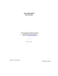
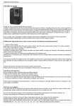
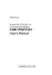
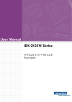
UM10492 PTN3460 eDP to LVDS bridge IC application board Rev. 1.1 — 16 March 2015 User manual Document information Info Content Keywords PTN3460, DisplayPort, eDP, LVDS, bridge, application board Abstract This user manual presents demonstration/application board capability of interfacing an (embedded) DisplayPort source to an LVDS panel. The application board (nicknamed ‘DPLVDS1’) is intended for use as an evaluation and customer demonstration tool, as well as a reference design. UM10492 NXP Semiconductors PTN3460 eDP to LVDS bridge IC application board Revision history Rev Date Description 1.1 20150316 Table 3; Removed remark for JP10 1 20140903 User manual; initial release Contact information For more information, please visit: http://www.nxp.com For sales office addresses, please send an email to: [email protected] UM10492 User manual All information provided in this document is subject to legal disclaimers. Rev. 1.1 — 16 March 2015 © NXP Semiconductors N.V. 2015. All rights reserved. 2 of 14 UM10492 NXP Semiconductors PTN3460 eDP to LVDS bridge IC application board 1. Introduction This user manual describes the PTN3460 application board with 1080p LCD panel made by AUO (part number M215HW03 V1), including: • Overall PCB connectors, jumpers, and power supplies • Equipment/tools that this board interfaces with during bench testing • System-level connections, such as cables and connectors, into which this board will be plugged This application board is intended to demonstrate the bridging capabilities of PTN3460 on DP to LVDS conversion. It is also used to evaluate competitor’s ICs such as Parade’s PS8615, which is pin-to-pin compatible with PTN3460. A separate document, “Application test plan” will be provided to list items to be verified at the system level. 1.1 Purpose • For internal engineers to evaluate the performance of PTN3460 and to develop firmware, including collecting and verifying system-level features, performance, and functionality, such as: – Verify power management schemes – Power sequence – Power consumption measurement during various operating modes – Allow access to test points and jumpers for measurement and configuration purposes – Flash over AUX – Programming test via I2C-bus • For marketing to demonstrate DP-LVDS to customers in the field – Functional and interoperability test – This board should be connected to a DP or an eDP source – This board is powered by ATX 20-pin power supply, or – External power supplies with +3.3 V (1 A), +5 V (1 A), +12 V (2 A) – This board is connected directly to AUO 21-inch LVDS panel, or – Connect to NoteBook 14-inch LVDS panel via an AUO-NB adaptor board • For customers to evaluate PTN3460 – Use I2C-bus to program EDID UM10492 User manual All information provided in this document is subject to legal disclaimers. Rev. 1.1 — 16 March 2015 © NXP Semiconductors N.V. 2015. All rights reserved. 3 of 14 UM10492 NXP Semiconductors PTN3460 eDP to LVDS bridge IC application board 2. General description 2.1 Block diagram Fig 1. DP-LVDS block diagram UM10492 User manual All information provided in this document is subject to legal disclaimers. Rev. 1.1 — 16 March 2015 © NXP Semiconductors N.V. 2015. All rights reserved. 4 of 14 UM10492 NXP Semiconductors PTN3460 eDP to LVDS bridge IC application board 2.2 PCB stack ups Fig 2. DP-LVDS PCB stack up example UM10492 User manual All information provided in this document is subject to legal disclaimers. Rev. 1.1 — 16 March 2015 © NXP Semiconductors N.V. 2015. All rights reserved. 5 of 14 xxxx xxxxxxxxxxxxxxxxxxxxxxxxxxxxxx x xxxxxxxxxxxxxx xxxxxxxxxx xxx xxxxxx xxxxxxxxxxxxxxxxxxxxxxx xxxxxxxxxxxxxxxxxxxxxx xxxxx xxxxxx xx xxxxxxxxxxxxxxxxxxxxxxxxxxxxx xxxxxxxxxxxxxxxxxxxxxx xxxxxxxxxxx xxxxxxx xxxxxxxxxxxxxxxxxxx xxxxxxxxxxxxxxxx xxxxxxxxxxxxxx xxxxxx xx xxxxxxxxxxxxxxxxxxxxxxxxxxxxxxxx xxxxxxxxxxxxxxxxxxxxxxxx xxxxxxx xxxxxxxxxxxxxxxxxxxxxxxxxxxxxxxxxxxxxxxxxxxxxx xxxxxxxxxxx xxxxx x x UM10492 6 of 14 © NXP Semiconductors N.V. 2015. All rights reserved. PTN3460 eDP to LVDS bridge IC application board 2.3 PTN3460 application board top and bottom assemblies Rev. 1.1 — 16 March 2015 All information provided in this document is subject to legal disclaimers. PTN3460 application board top assembly NXP Semiconductors UM10492 User manual Fig 3. xxxx xxxxxxxxxxxxxxxxxxxxxxxxxxxxxx x xxxxxxxxxxxxxx xxxxxxxxxx xxx xxxxxx xxxxxxxxxxxxxxxxxxxxxxx xxxxxxxxxxxxxxxxxxxxxx xxxxx xxxxxx xx xxxxxxxxxxxxxxxxxxxxxxxxxxxxx xxxxxxxxxxxxxxxxxxxxxx xxxxxxxxxxx xxxxxxx xxxxxxxxxxxxxxxxxxx xxxxxxxxxxxxxxxx xxxxxxxxxxxxxx xxxxxx xx xxxxxxxxxxxxxxxxxxxxxxxxxxxxxxxx xxxxxxxxxxxxxxxxxxxxxxxx xxxxxxx xxxxxxxxxxxxxxxxxxxxxxxxxxxxxxxxxxxxxxxxxxxxxx xxxxxxxxxxx xxxxx x x NXP Semiconductors UM10492 User manual PTN3460 application board bottom assembly UM10492 7 of 14 © NXP Semiconductors N.V. 2015. All rights reserved. Fig 4. PTN3460 eDP to LVDS bridge IC application board Rev. 1.1 — 16 March 2015 All information provided in this document is subject to legal disclaimers. BOTTOM ASSEMBLY UM10492 NXP Semiconductors PTN3460 eDP to LVDS bridge IC application board The PTN3460 AUO application board has the following features: • • • • • • • • • • • • • Jumpers select multiplex between DP and eDP (iMac) sources Stuff options for PTN3460 different pin configurations Stuff options for PS8615 test Four (4) groups of jumpers for pin configuration Other jumpers for test options One serial EEPROM to store EDID read/write via I2C-bus One I2C-bus header bringing out I2C-bus pins (SCL, SDA, GND) to interface with an I2C Bird (I2C tool device name) dongle to program S-EEPROM or to read iMac System Bus One I2C-bus header for DDC control One JTAG for firmware download One ATX 20-pin power supply with 12 V/5 V/3.3 V DC inputs External power supplies: +12 V (2 A), +5 V (1 A), +3.3 V (1 A) Fixed regulator provides 1.8 V 10 % power supply Two soft-touch connectors (not loaded) for Agilent differential probes to capture LVDS signals • One 30-position, 1 mm connector with cables to connect to AUO 21-inch LVDS panel • One 1 8 connector with cable to connect to backlight inverter 3. Hardware requirements • iMac 27-inch AIO, eDP source with 30-position eDP cable • VTG5225-DP, DP source with DP 1.1 cable • DPA-400, AUX analyzer, via iMac eDP-DP adaptor with two DP 1.1 cables and two 30-position eDP cables • • • • • UFG-04, LVDS grabber, via AUO-grabber adaptor with two MDR-26 twisted cables Desktop PC with PCIe slot to install LVDS grabber AUO 21-inch LVDS panel with 30-position LVDS cable FS2 with 2 5 JTAG connection for firmware download I2C Bird with 1 4 header connection for s-EEPROM read/write 4. Board specifications • • • • • UM10492 User manual Layers: four layers expected — trace, ground, VCC, trace Size: 4 inches 6 inches Material: FR4 Thickness: 62 mil Impedance: 50 single-ended, 100 differential on DP and LVDS signal pairs All information provided in this document is subject to legal disclaimers. Rev. 1.1 — 16 March 2015 © NXP Semiconductors N.V. 2015. All rights reserved. 8 of 14 UM10492 NXP Semiconductors PTN3460 eDP to LVDS bridge IC application board 5. Connector specifications 5.1 Connectors Table 1. Connectors Connector Type J1 DP CONN SINK J2 FI-X30SSL-HF J3, J5 HEADER 4 J4 HEADER, 2 5 Supplier Part number conn-47272-0001 Molex 47272-0001 conn_FI-X30SSL-HF JAE FI-X30SSL-HF hdr_4x1 Sullins PBC04SAAN hdr_5x2 Sullins PBC05DAAN J6, J8 SOFT TOUCH CONN ES387-68701 conn_ES387-68701 Agilent ES387-68701 J7 FI-XB30SRL-HF11 conn_FI-XB30SRL-HF11 JAE FI-XB30SRL-HF11 J9 MOLEX ATX PWR PN 39-29-9202 cn_molex_minfit20p_vt Molex 39-29-9202 CN1 S8B-PH-SM4-TB(LF)(SN) conn_8x1_2mm JST Sales S8B-PH-SM4-TB(LF)(SN) 5.2 Cables Table 2. Cables Test cable location Test cable Description J1 DP 1.1 cable Purchase ready-made cable J2 iMac 30-position eDP 1 mm cable Made from LVDS 30-position cable kit J3, J5 I2C J4 JTAG 2 5 ribbon cable Ready-made with FS2 box J6, J8 Agilent soft-touch probes 90-pin differential probe E5387A (2) J7 AUO 30-position LVDS 1 mm cable Made from LVDS 30-position cable kit J9 Backlight inverter 1 8 Made from accessories Bird 1 4 cable Ready-made with I2C Bird box 5.3 Jumpers Table 3. Jumpers Jumper number Signal names Jumper settings Default setting JP1 U1 MUX GPU_SEL 1-2 HIGH — select DP inputs 1-2 JP2 U1 MUX AUX_SEL 1-2 HIGH — select AUX from DP inputs 1V8_PTN 1-2 — 1.8 V from on-board regulator JP3 2-3 LOW — select eDP inputs 1-2 2-3 LOW — select AUX from eDP inputs 1-2 2-3 — 1.8 V from Buck converter JP4 TESTMODE 1-2 HIGH — CFG[4:1] = JTAG pins 2-3 2-3 LOW — CFG[4:1] = CONFIG pins JP5 DEV_CFG 1-2 HIGH — I2C-bus master open — I2C-bus 2-3 slave (0C0h) 2-3 LOW — I2C-bus slave (040h) UM10492 User manual All information provided in this document is subject to legal disclaimers. Rev. 1.1 — 16 March 2015 © NXP Semiconductors N.V. 2015. All rights reserved. 9 of 14 UM10492 NXP Semiconductors PTN3460 eDP to LVDS bridge IC application board Table 3. Jumpers …continued Jumper number Signal names Jumper settings Default setting JP6 CFG4/TDO 1-2 HIGH — LVDS output swing = 400 mV 1-2 open — LVDS output swing = 300 mV 2-3 LOW — LVDS output swing = 250 mV JP7 CFG3/TDI 1-2 HIGH — LVDS clock frequency = 0.5 % 1-2 open — LVDS clock frequency = 1 % 2-3 LOW — LVDS clock frequency = 0 % JP8 PD_N 1-2 HIGH — Operation mode 1-2 2-3 LOW — Force power-down JP9 CFG2/TMS 1-2 HIGH — JEIDA or VESA format (18 bpp) 1-2 open — JEIDA format (24 bpp) 2-3 LOW — VESA format (24 bpp) JP10 CFG1/TCK 1-2 HIGH — Dual LVDS bus 1-2 2-3 LOW — Single LVDS bus JP11 EPS_N ON — Use external 3.3 V/1.8 V option 1-2 OFF — Use internal 1.8 V LDO JP12 WP 1-2 HIGH — WP for S-EEPROM 2-3 2-3 LOW — No WP S-EEPROM JP13 VDD_VOL JP14 +INV_PWR 1-2 — select +3V3 for panel 1-2 2-3 — select +5V for panel 1-2 — select +5V for backlight inverter 1-2 2-3 — select +12V for backlight inverter JP15 BKLTEN_CN 1-2 HIGH — Backlight enable is always ON 1-2 2-3 BKLTEN — Control by firmware JP16 PVCCEN_PTN 1-2 HIGH — PVCCEN is always ON 1-2 2-3 PVCCEN — Control by firmware JP17 PVCCEN 1-2 HIGH — I2C_ADDR 0xB0h to 0xBFh (for PS8615 only) (pin 33 is used as I2C_Addr/GPIO in PS8615) 2-3 LOW — I2C_ADDR 0x10h to 0x1Fh not loaded JP18 +12V 1-2 — select from ATX power supply 2-3 2-3 — select from external power supply JP19 +1V8 JP20 +5V 1-2 — select from U4 regulator 1-2 2-3 — select from external power supply 1-2 — select from ATX power supply 2-3 2-3 — select from external power supply JP21 +3V3 1-2 — select from ATX power supply 2-3 2-3 — select from external power supply JP22 AIOC_HPD ON — HPD drives Green LED 1-2 OFF — No LED drive to measure power UM10492 User manual All information provided in this document is subject to legal disclaimers. Rev. 1.1 — 16 March 2015 © NXP Semiconductors N.V. 2015. All rights reserved. 10 of 14 UM10492 NXP Semiconductors PTN3460 eDP to LVDS bridge IC application board 6. Stuffing options 0.1µF 0.1µF 6.1 PTN3460 NXP pinning VDD18 43 44 45 46 47 48 49 50 51 52 53 42 2 41 3 40 4 39 5 38 6 37 7 36 PTN3460 8 35 28 27 26 25 24 23 15 22 29 21 30 14 20 31 13 19 32 12 18 33 11 17 34 10 16 0.1µF 9 VDD33 0.1µF 0.01µF 0.1µF 1µF FB 54 VDD18 55 56 FB 1 0.1µF 4.7µF 0.1µF VDD18 4.7µF Fig 5. PTN3460 pinning 6.2 Stuffing locations Table 4. UM10492 User manual Stuffing locations Location Function/value PTN3460 (default pinning) R16 Join +3V3_IO with +3V3_LDO no load R17 Pin 27 = CFG4/TDO load R18 Pin 26 = BKLTEN_PTN load R19 Pin 28 - PWMO_PTN load R20 Pin 32 = LVSDE_N_PTN load R21 Pin 31 = LVSDE_P_PTN load R22 Pin 32 = PWMO no load R23 Pin 31 = BKLTEN no load R24 +3V3_LDO for pin 13, 14 load R25 Pin 28 = GND no load R26 Pin 26 = GND no load R27 Pin 27 = GND no load C27 1 F for RST_N line no load C22 0.47 F no load All information provided in this document is subject to legal disclaimers. Rev. 1.1 — 16 March 2015 © NXP Semiconductors N.V. 2015. All rights reserved. 11 of 14 UM10492 NXP Semiconductors PTN3460 eDP to LVDS bridge IC application board Table 4. Stuffing locations …continued Location Function/value PTN3460 (default pinning) C23 4.7 F no load L4 FB no load C25 0.47 F no load C26 4.7 F no load L5 10 H no load C15 2.2 F load 7. Abbreviations Table 5. Abbreviations Acronym Description AUO Active User Object DP DisplayPort EDID Extended Display Identification Data eDP embedded DisplayPort EEPROM Electrically Erasable Programmable Read-Only Memory I2C-bus Inter-Integrated Circuit-bus IC Integrated Circuit JTAG Joint Test Action Group LED Light-Emitting Diode LDO Low-DropOut regulator LVDS Low-Voltage Differential Signalling NB NoteBook PC Personal Computer PCB Printed-Circuit Board 8. References UM10492 User manual [1] Data Specification, PTN3460_DP_LVDS_Bridge_v1.7.pdf [2] Schematic, DP-LVDS-AUO rev1.14 rew.pdf [3] BOM, DP-LVDS-AUO rev1.14.xls [4] PTN3460 PCB Layout Guideline.pdf [5] Allegro layout, PTN3460 Evaluation eDP-LVDS AUO Board_PCB_0089_021811-1.brd [6] Test Cables, PTN3460 Test Cables.pdf All information provided in this document is subject to legal disclaimers. Rev. 1.1 — 16 March 2015 © NXP Semiconductors N.V. 2015. All rights reserved. 12 of 14 UM10492 NXP Semiconductors PTN3460 eDP to LVDS bridge IC application board 9. Legal information 9.1 Definitions Draft — The document is a draft version only. The content is still under internal review and subject to formal approval, which may result in modifications or additions. NXP Semiconductors does not give any representations or warranties as to the accuracy or completeness of information included herein and shall have no liability for the consequences of use of such information. 9.2 Disclaimers Limited warranty and liability — Information in this document is believed to be accurate and reliable. However, NXP Semiconductors does not give any representations or warranties, expressed or implied, as to the accuracy or completeness of such information and shall have no liability for the consequences of use of such information. NXP Semiconductors takes no responsibility for the content in this document if provided by an information source outside of NXP Semiconductors. In no event shall NXP Semiconductors be liable for any indirect, incidental, punitive, special or consequential damages (including - without limitation - lost profits, lost savings, business interruption, costs related to the removal or replacement of any products or rework charges) whether or not such damages are based on tort (including negligence), warranty, breach of contract or any other legal theory. Notwithstanding any damages that customer might incur for any reason whatsoever, NXP Semiconductors’ aggregate and cumulative liability towards customer for the products described herein shall be limited in accordance with the Terms and conditions of commercial sale of NXP Semiconductors. Right to make changes — NXP Semiconductors reserves the right to make changes to information published in this document, including without limitation specifications and product descriptions, at any time and without notice. This document supersedes and replaces all information supplied prior to the publication hereof. Suitability for use — NXP Semiconductors products are not designed, authorized or warranted to be suitable for use in life support, life-critical or safety-critical systems or equipment, nor in applications where failure or malfunction of an NXP Semiconductors product can reasonably be expected to result in personal injury, death or severe property or environmental damage. NXP Semiconductors and its suppliers accept no liability for inclusion and/or use of NXP Semiconductors products in such equipment or applications and therefore such inclusion and/or use is at the customer’s own risk. Applications — Applications that are described herein for any of these products are for illustrative purposes only. NXP Semiconductors makes no representation or warranty that such applications will be suitable for the specified use without further testing or modification. Customers are responsible for the design and operation of their applications and products using NXP Semiconductors products, and NXP Semiconductors accepts no liability for any assistance with applications or customer product UM10492 User manual design. It is customer’s sole responsibility to determine whether the NXP Semiconductors product is suitable and fit for the customer’s applications and products planned, as well as for the planned application and use of customer’s third party customer(s). Customers should provide appropriate design and operating safeguards to minimize the risks associated with their applications and products. NXP Semiconductors does not accept any liability related to any default, damage, costs or problem which is based on any weakness or default in the customer’s applications or products, or the application or use by customer’s third party customer(s). Customer is responsible for doing all necessary testing for the customer’s applications and products using NXP Semiconductors products in order to avoid a default of the applications and the products or of the application or use by customer’s third party customer(s). NXP does not accept any liability in this respect. Export control — This document as well as the item(s) described herein may be subject to export control regulations. Export might require a prior authorization from competent authorities. Evaluation products — This product is provided on an “as is” and “with all faults” basis for evaluation purposes only. NXP Semiconductors, its affiliates and their suppliers expressly disclaim all warranties, whether express, implied or statutory, including but not limited to the implied warranties of non-infringement, merchantability and fitness for a particular purpose. The entire risk as to the quality, or arising out of the use or performance, of this product remains with customer. In no event shall NXP Semiconductors, its affiliates or their suppliers be liable to customer for any special, indirect, consequential, punitive or incidental damages (including without limitation damages for loss of business, business interruption, loss of use, loss of data or information, and the like) arising out the use of or inability to use the product, whether or not based on tort (including negligence), strict liability, breach of contract, breach of warranty or any other theory, even if advised of the possibility of such damages. Notwithstanding any damages that customer might incur for any reason whatsoever (including without limitation, all damages referenced above and all direct or general damages), the entire liability of NXP Semiconductors, its affiliates and their suppliers and customer’s exclusive remedy for all of the foregoing shall be limited to actual damages incurred by customer based on reasonable reliance up to the greater of the amount actually paid by customer for the product or five dollars (US$5.00). The foregoing limitations, exclusions and disclaimers shall apply to the maximum extent permitted by applicable law, even if any remedy fails of its essential purpose. Translations — A non-English (translated) version of a document is for reference only. The English version shall prevail in case of any discrepancy between the translated and English versions. 9.3 Trademarks Notice: All referenced brands, product names, service names and trademarks are the property of their respective owners. All information provided in this document is subject to legal disclaimers. Rev. 1.1 — 16 March 2015 © NXP Semiconductors N.V. 2015. All rights reserved. 13 of 14 UM10492 NXP Semiconductors PTN3460 eDP to LVDS bridge IC application board 10. Contents 1 1.1 2 2.1 2.2 2.3 3 4 5 5.1 5.2 5.3 6 6.1 6.2 7 8 9 9.1 9.2 9.3 10 Introduction . . . . . . . . . . . . . . . . . . . . . . . . . . . . 3 Purpose . . . . . . . . . . . . . . . . . . . . . . . . . . . . . . 3 General description . . . . . . . . . . . . . . . . . . . . . . 4 Block diagram . . . . . . . . . . . . . . . . . . . . . . . . . . 4 PCB stack ups . . . . . . . . . . . . . . . . . . . . . . . . . 5 PTN3460 application board top and bottom assemblies . . . . . . . . . . . . . . . . . . . . . . . . . . . . 6 Hardware requirements. . . . . . . . . . . . . . . . . . . 8 Board specifications . . . . . . . . . . . . . . . . . . . . . 8 Connector specifications . . . . . . . . . . . . . . . . . 9 Connectors . . . . . . . . . . . . . . . . . . . . . . . . . . . . 9 Cables . . . . . . . . . . . . . . . . . . . . . . . . . . . . . . . 9 Jumpers . . . . . . . . . . . . . . . . . . . . . . . . . . . . . . 9 Stuffing options . . . . . . . . . . . . . . . . . . . . . . . . 11 PTN3460 NXP pinning . . . . . . . . . . . . . . . . . . 11 Stuffing locations. . . . . . . . . . . . . . . . . . . . . . . 11 Abbreviations . . . . . . . . . . . . . . . . . . . . . . . . . . 12 References . . . . . . . . . . . . . . . . . . . . . . . . . . . . 12 Legal information. . . . . . . . . . . . . . . . . . . . . . . 13 Definitions . . . . . . . . . . . . . . . . . . . . . . . . . . . . 13 Disclaimers . . . . . . . . . . . . . . . . . . . . . . . . . . . 13 Trademarks. . . . . . . . . . . . . . . . . . . . . . . . . . . 13 Contents . . . . . . . . . . . . . . . . . . . . . . . . . . . . . . 14 Please be aware that important notices concerning this document and the product(s) described herein, have been included in section ‘Legal information’. © NXP Semiconductors N.V. 2015. All rights reserved. For more information, please visit: http://www.nxp.com For sales office addresses, please send an email to: [email protected] Date of release: 16 March 2015 Document identifier: UM10492