1
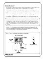
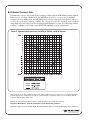
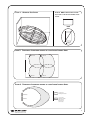
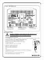
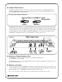
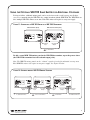
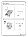
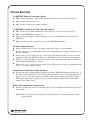
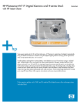
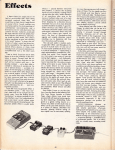
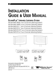
INSTALLATION GUIDE &
USER MANUAL
Sound Plus™ Infrared Listening System
Model WIR TX90, Two Channel System
Model WIR SYS 90V, Two Channel System
Model WIR SYS 90 PRO, Two Channel System
Transmitter Model WIR TX90
Optional Receiver Models WIR RX22-4, WIR RX14-2, WIR RX18
Optional Charger Models CHG 518, CHG 3512
MAN 119E
SOUNDPLUS™ INFRARED LISTENING SYSTEM,
Model WIR TX90, Two-Channel Listening System
Model WIR SYS 90V, Two-Channel Listening System
Model WIR SYS PRO, Two-Channel Listening System
INSTALLATION GUIDE & USER MANUAL
CONTENTS
PAGE
System Overview . . . . . . . . . . . . . . . . . . . . . . . . . . . . . . . . . . . . . . . . . . . . . . . . . . . . . . . . 3
Installation Procedures
Determining Coverage Area . . . . . . . . . . . . . . . . . . . . . . . . . . . . . . . . . . . . . . . . . . . . . .4
Connect Power . . . . . . . . . . . . . . . . . . . . . . . . . . . . . . . . . . . . . . . . . . . . . . . . . . . . . . . .6
Connect Audio Source . . . . . . . . . . . . . . . . . . . . . . . . . . . . . . . . . . . . . . . . . . . . . . . . . .7
Selecting a Frequency . . . . . . . . . . . . . . . . . . . . . . . . . . . . . . . . . . . . . . . . . . . . . . . . . .7
Select an Application Preset . . . . . . . . . . . . . . . . . . . . . . . . . . . . . . . . . . . . . . . . . . . . . .8
Adjusting Audio Inputs . . . . . . . . . . . . . . . . . . . . . . . . . . . . . . . . . . . . . . . . . . . . . . . . .8
Adjusting Tone . . . . . . . . . . . . . . . . . . . . . . . . . . . . . . . . . . . . . . . . . . . . . . . . . . . . . . . .8
Using the optional WIR TX9 Emitter for Additional Coverage . . . . . . . . . . . . . . . . . . . .9
Receiver Safety . . . . . . . . . . . . . . . . . . . . . . . . . . . . . . . . . . . . . . . . . . . . . . . . . . . . . . . . .10
Optional IR Receiver Instructions . . . . . . . . . . . . . . . . . . . . . . . . . . . . . . . . . . . . . . . . . .11
Trouble Shooting . . . . . . . . . . . . . . . . . . . . . . . . . . . . . . . . . . . . . . . . . . . . . . . . . . . . . . .13
Warranty . . . . . . . . . . . . . . . . . . . . . . . . . . . . . . . . . . . . . . . . . . . . . . . . . . . . . . . . . . . . . .14
Specifications . . . . . . . . . . . . . . . . . . . . . . . . . . . . . . . . . . . . . . . . . . . . . . . . . . . . . . . . . .15
2
SYSTEM OVERVIEW
The WIR TX90 two channel infrared transmitter combines infrared modulator and emitter technology into a
single mountable enclosure - reducing operating cost and eliminating precious rack space.
The WIR TX90 features an easy to use configuration preset for Music, Voice, or Hearing Assistance
Applications. It operates on dual 2.3/2.8 or 3.3/3.8 MHz selectable frequencies - ideal for high quality audio
programs such as music, theater and audio description. The WIR TX90 will accept any line level, balanced or
unbalanced audio inputs, and includes adjustable tone and volume control. Infrared receivers detect the transmission and convert the light signals back into audio signals. The 2.3-3.8 MHz operating frequencies minimize high efficiency lighting interference.
No FCC license or radio approval is required with this equipment. It can be used anywhere in the world.
NOTE: This equipment has been tested and found to comply with the limits for a Class A digital device, pursuant to part 15 of the FCC Rules. These limits are designed to provide reasonable protection against harmful
interference when the equipment is operated in a commercial environment. This equipment generates, uses,
and can radiate radio frequency energy and, if not installed and used in accordance with the instruction manual, may cause harmful interference to radio communications. Operation of this equipment in a residential area
is likely to cause harmful interference in which case the user will be required to correct the interference at his
own expense.
NOTICE: A PLASMA MONITOR CAN DEGRADE THE AUDIO QUALITY OF THE WIR TX90
TRANSMITTER. FOR BEST PERFORMANCE, THE TRANSMITTER SHOULD BE POSITIONED
AS FAR AWAY FROM THE PLASMA MONITOR AS POSSIBLE.
FIGURE 1: TYPICAL TWO-CHANNEL
CONFIGURATION FOR THE
WIR TX90
3
u DETERMINE COVERAGE AREA
Determine the coverage area needed for the seating area. When using the WIR TX90 transmitter with the
RX22-4 receiver, in single channel mode, the WIR TX90 can achieve a coverage area of 28,000 ft2
(2,600 m2). In four channel mode, the WIR TX90 divides its power among the four signals to achieve a
coverage area of 11,000 ft2 (1,022 m2). NOTE: The coverage area will vary depending on the sensitivity
of the infrared receiver being used. The following diagram illustrates coverage area when using a RX224, RX14-2, or RX18 receiver with a single WIR TX90 transmitter in single channel mode.
FIGURE 2: MAXIMUM
RANGE WHEN USING THE
RX22-4, RX14-2,
OR
RX18 RECEIVER
These patterns are the direct radiation pattern. The infrared radiation does not drop to zero outside the illustrated
patterns; it decreases. It still may be useable at a greater distance, depending on the receiver sensitivity and the
reflective characteristics of the room.
Reflections of the infrared light from walls, ceilings, and floors may change these patterns.
Important: Remember to point the transmitter towards the listening audience!
Remember: opaque objects block infrared light. Thus, the transmitter cannot be concealed behind opaque walls, curtains, etc.
4
FIGURE 3: 3 DIMENSION FOOT PATTERN
FIGURE 5: OVERLAPPING ILLUMINATION
FIGURE 4: NOTE: WHEN POINTING THE EMITTER, BE SURE TO KEEP THE LONG DIMENSION HORIZONTAL.
PATTERNS TO COVER LARGER LISTENING
WIR TX90
WIR TX9
WIR TX9
WIR TX9
FIGURE 6: OVERLAPPING ILLUMINATION
PATTERNS TO COVER LARGER LISTENING
AREAS
AREAS
Coverage Area
with Single Transmitter
WIR TX90
WIR TX9
Coverage Area
with Second Emitter
Added to Same
Emission Point
(50% increase)
5
FIGURE 7: WIR TX90 REAR VIEW
Power Connection
Plug in Power Supply
120 VAC (US): TFP 010
230 VAC (CE): TFP 027
Wall/Ceiling
Mounting Bracket (BKT 024)
Set of threaded holes for use
with mounting bracket
Baseband Out
BNC Connector, 50 Ω
50 kHz-8 MHz Baseband
u CONNECT POWER
WARNING: POWERLINE VOLTAGE MUST NOT FALL BELOW 90V, 0R
SYSTEM PERFORMANCE WILL BE GREATLY REDUCED!
POWER CONNECTION FOR U.S. APPLICATION
Connect the TFP 010 power supply to the 3-pin Molex™ connector located on the rear of the TX90 (see Figure 8, below).
FOR APPLICATIONS OUTSIDE THE U.S. REQUIRING 240 VAC MAINS SUPPLY:
Use the transformer power supply, model TFP 027. Make sure
TFP 027 power input switch (located on bottom of power supply)
is set to the “230” position.
Secondary specifications: 24 VAC, 35 VA, 50/60 Hz.
Plug the power supply into the AC outlet.
TFP 027-01: 230VAC, Euro Mains Plug
TFP 027-02: 230VAC, UK Mains Plug
NOTE:
The WIR TX90 transmits when a baseband signal is present, and will shut off immediately when
no baseband signal is present. This auto shut-off feature preserves the life of the infrared LEDs
and reduces power consumption.
This system is designed for class 2, low-voltage wiring. Always follow
local electrical codes when doing low voltage wiring.
6
FIGURE 8
Power In Jack
u CONNECT AUDIO SOURCE
Determine the length of the audio cable needed to connect to the sound system to the WIR TX90 transmitter.
Install the supplied Phoenix connector on the end of the audio cable to be connected to the transmitter. See the
back of the WIR TX90 for wiring instructions.
FIGURE 9: AUDIO SOURCE CONNECTIONS
The WIR TX90 will accept line level, balanced or unbalanced audio inputs. If you wish to operate in single channel mode, plug the audio cable with the installed Phoenix connector in “Channel A” OR the “Channel B” connector. If you choose to operate in two channel mode, plug the audio cables with Phoenix connectors in both “Channel
A” AND “Channel B” connector. NOTE: By default, the WIR TX90 is set to operate in two-channel mode. To
turn Channel A or Channel B on/off, refer to the instructions Selecting a Channel, below.
FIGURE 10
Pow er no In
dicator
u SELECTING
The WIR TX90 offers two sets of carrier frequencies for Channel A and Channel B:
2.3 and 2.8MHz or 3.3 and 3.8MHz.
A
CARRIER FREQUENCY PAIR
The WIR TX90 is preset to 2.3 and 2.8 MHz, which are the most commonly used. Move the slide switch to select
a pair of operating frequencies.
u SELECTING
CHANNEL
To activate a channel, press the “CHANNEL” button until the channel “ON” indicator lights. For example, to operate only channel A, press the “CHANNEL” button until only the channel A “ON” indicator lights. To operate both
channel A and B, press the “CHANNEL” button until both “ON” indicators light.
A
Note: If you’re only using one channel, make sure the other channel is turned off to maximize system coverage.
7
u SELECT
AUDIO PROCESSING APPLICATION PRESET
The WIR TX90 offers three preset audio processing options for the most common applications: Music, Voice, and
Hearing Assist. Use the “Music” setting when maximum dynamic range and audio quality are preferred. Use the
“Voice” setting for simultaneous interpretation, audio description, or other applications with users that have primarily normal hearing. Use the “Assist” setting for hearing assistance applications to meet the reduced dynamic range
needs of hearing impaired listeners. You may select the same audio pre-set for both Channel A and Channel B, or
you may select them independently.
THE
To select the audio processing preset, you must first activate the channel you want to adjust. Press the “channel”
button to activate the channel(s) you want to choose an audio processing preset for, then press the “Presets” button
to choose the preset. The Music, Voice, or Assist indicator will light to show your selection. After 10 seconds, the
setting will be stored.
u ADJUST AUDIO INPUT LEVEL
The TX90 is designed to accept a line-level audio input signal. The “Level” indicator light for each
channel is used to help adjust the audio input level. When the indicator does not light, the input signal
level is too low. When the indicator is flashing, the signal level is optimal. When the indicator is steadily
lit, but does not flash, the input level is too high and can cause distortion. You can adjust the input level
of both channels simultaneously, or independently.
Make sure the input audio signal is connected to the WIR TX90. To adjust the audio input level, first activate the channel(s) you want to adjust by pressing the “CHANNEL” button, then press the “VOLUME”
button. The Volume indicator will light. Now, turn the “ADJUST” knob clockwise to increase the input
signal or counter-clockwise to decrease the input signal until the channel “Level” indicator is flashing.
After 10 seconds, the setting will be stored.
IMPORTANT * *
Audio level NORMAL (optimal): the audio indicator level will flash at a 1 second rate.
Audio level too HIGH: the audio indicator level will stay on or flash erratically.
Audio level too LOW: the audio indicator level will be off.
**
u ADJUST TONE
The WIR TX90 has a tone adjustment to suit user preference and to compensate for the different frequency responses of various infrared receiver models. First, make sure the audio source is active. Use a
receiver from the system to listen to the signal as you adjust the tone control.
To adjust the tone, first activate the channel(s) you want to adjust by pressing the “CHANNEL” button,
then press the “TONE” button. The tone indicator will light. Now turn the “ADJUST” knob clockwise to
emphasize high frequencies (best for hearing assistance use). When you have reached the maximum
adjustment, there will be no further change in tone. Turn the “ADJUST” knob counter-clockwise to
decrease the high frequency emphasis. When you have reached the minimum adjustment, there will be
no further change in tone. After 10 seconds, the setting will be stored.
8
USING
THE
OPTIONAL WIR TX9 SLAVE EMITTER
FOR
ADDITIONAL COVERAGE
For larger facilities, additional emitter panels can be used to increase the overall coverage area. In these
cases, we recommend using the WIR TX9 slave emitter in tandem with the WIR TX90. The WIR TX90 can
drive multiple WIR TX9 emitters at one time. Each TX9 emitter will require its own power supply.
FIGURE 11: CONNECTING
A
WIR TX9 EMITTER
TO A
WIR TX9 Emitter (Rear)
WIR TX90 TRANSMITTER
WIR TX90 Transmitter (Rear)
Baseband
Input
Baseband
Output
To TX9 Emitter
To add a second WIR TX9 emitter panel to the WIR TX90 transmitter, repeat the process above
(the WIR TX90 transmitter has two baseband output jacks).
Note: The WIR TX9 emitter panels can be “chained” together if needed for unlimited coverage area.
Each WIR TX9 emitter will require its own power supply. See Figure 12 below.
FIGURE 12: CHAINING
MULTIPLE
WIR TX9 Emitter #2 (Rear)
Baseband
Output
To additional Emitters
WIR TX9 EMITTERS TOGETHER
WIR TX9 Emitter #1 (Rear)
Baseband
Input
Baseband
Output
To Second TX9 Emitter
WIR TX90 Transmitter (Rear)
Baseband
Input
Baseband
Output
To TX9 Emitter
Baseband
Output
To Additional Emiters
9
RECEIVER SAFETY INFORMATION
HEARING SAFETY
Williams Sound receivers are designed to amplify sounds to a high volume level which could potentially
cause hearing damage if used improperly. To protect your hearing and the hearing of others:
CAUTION!
1.
2.
3.
4.
BATTERY SAFETY
Make sure the volume is turned down before putting on the earphone or headphone before
adjusting the volume to a comfortable level.
Set the volume level at the minimum setting that you need to hear.
If you experience feedback (a squealing or howling sound), reduce the volume setting and move
the microphone away from the earphone or headphone.
Do not allow children o r o t h e r u n a u t h o r i z e d p e r s o n s to have access to the receiver.
AND
DISPOSAL
Williams Sound receivers are supplied with disposable Alkaline batteries. Do not attempt to recharge
disposable batteries, which may explode, release dangerous chemicals, cause burns, or other serious
harm to the user or product.
CAUTION!
PACEMAKER SAFETY
1.
Before using Williams Sound receivers with a pacemaker or other medical device, consult your
physician or the manufacturer of your pacemaker or other medical device.
CAUTION!
2.
If you have a pacemaker or other medical device, make sure that you are using the Williams
Sound receiver in accordance with safety guidelines established by your physician or the pacemaker manufacturer.
RECYCLING INSTRUCTIONS
BATTERY SAFETY
Help Williams Sound protect the environment! Please take the time to dispose of your equipment
properly.
AND
DISPOSAL
P r od u c t R e c y c l i n g f o r C u s to m e r s i n th e Eu r op e an U n i o n :
Please do NOT dispose of your Williams Sound equipment in the household trash. Please take
the equipment to a electronics recycling center; OR return the product to the factory for proper
disposal.
Ba t t e r y R e c yc l i n g fo r C u st o me r s i n t h e E u r o p e a n U n i o n :
Please do NOT dispose of used batteries in the household trash. Please take the batteries to a
retail or community collection point for recycling.
11/20/07
10
OPTIONAL INFRARED RECEIVERS
FIGURE 13: FOUR CHANNEL RECEIVER, MODEL WIR RX22-4
Channel
1
2
3
4
Frequency
2.3 MHz
2.8 MHz
3.3 MHz
3.8 MHz
FIGURE 14: WIR RX14-2 HEADSET RECEIVER
FIGURE 15: WIR RX18 UNDER-THE-CHIN RECEIVER
WIR RX18 Front View
11
OPTIONAL CHARGERS
FIGURE 16: MULTIPLE BATTERY CHARGER, MODEL CHG 518
CHG 518 Top
CHG 518 Back
FIGURE 17: MULTIPLE BATTERY CHARGER, MODEL CHG 3512
CHG
WARNING: DO
NOT ATTEMPT
TO RECHARGE
DISPOSABLE BATTER
WARNING:
IES! DO NOT
CHG
ATTEMPT TO RECHA
RGE
CHG
Williams Sou
nd
DISPOSABLE BATTE
RIES!
CHG
Williams Soun
d
CHG
CHG
CHG
CHG
CHG
WARNING: DO
NOT ATTEM
PT TO RECHARGE
DISPOSABLE
BATTE
CHG
CHG
RIES!
WARNING: DO
NOT ATTE
MPT TO RECH
ARGE DISPOSABL
E BATTERIES
!
CHG
CHG 3512 Top
12
CHG 3512 Back
TROUBLE SHOOTING
THE WIR TX90 “POWER ON” INDICATOR IS NOT LIT.
þ Make sure the transformer is plugged into the transmitter and any remote power switch is on.
þ
þ
Make sure the electrical outlet is on.
Make sure the 24 VAC power supply is working.
THE WIR TX90’S CHANNEL A OR B “ON” INDICATOR IS NOT LIT.
þ Make sure the desired audio channel has been activated. See Selecting a Channel on page 7.
þ Make sure the WIR TX90 is plugged in.
þ Make sure the audio input is connected properly. See page 6 or instructions on the back of the
WIR TX90.
þ Make sure an active audio signal is being sent to the WIR TX90 transmitter.
NO SOUND THROUGH RECEIVERS.
þ Check to make sure the receiver is operating on the same frequency as the transmitter.
þ If some of the receivers work but others don’t, check for bad batteries or earphones on the receivers
that aren’t working.
þ If none of the receivers work, check to see if the power and audio input cable are connected to the
transmitter and that the WIR TX90 “Power On” and Channel A or B “On” indicator is illuminated.
þ Check to see if the transmitter is connected properly to the sound system. The audio level indicators
should flash on channels that are selected.
þ Make sure the “eye” is not covered up on the receiver. There must be clear line of sight between the
receiver eye and the transmitter panel.
SOUND THROUGH THE RECEIVERS IS WEAK AND NOISY.
þ Listen to the audio signal through the headphone jack on the WIR TX90 transmitter (Figure 10). If
the signal is weak and noisy here, try increasing the audio input level (see Adjust Audio Input Level,
page 8), or increase the input signal level from the sound system by turning up the mixer control.
If the signal sounds okay, you may need to reposition the transmitter panel or add additional IR
emitters to the TX90 system.
BUZZING OR HUMMING NOISE IN SOUND SYSTEM.
þ Check for ground loops or noise on the input signal. Call your Authorized Williams Sound dealer or
representative.
NOTE: Make sure the powerline voltage does not fall below 90V, or system performance will be
greatly reduced!
13
LIMITED WARRANTY
Williams Sound products are engineered, designed, and manufactured under carefully controlled conditions to provide you with many years of reliable service. Williams Sound warrants the Sound Plus™
Infrared Listening System against defects in materials and workmanship for FIVE (5) years. During the
first five years from the purchase date, we will promptly repair or replace the Sound Plus™ Infrared
Listening System.
Microphones, earphones, headphones, batteries, chargers, cables, carry cases, and all other accessory
products carry a 90-day warranty.
WILLIAMS SOUND HAS NO CONTROL OVER THE CONDITIONS UNDER WHICH THIS
PRODUCT IS USED. WILLIAMS SOUND, THEREFORE, DISCLAIMS ALL WARRANTIES NOT
SET FORTH ABOVE, BOTH EXPRESS AND IMPLIED, WITH RESPECT TO THE SOUND PLUS™
INFRARED LISTENING SYSTEM, INCLUDING BUT NOT LIMITED TO, ANY IMPLIED WARRANTY OF MERCHANTABILITY OR FITNESS FOR A PARTICULAR PURPOSE. WILLIAMS
SOUND SHALL NOT BE LIABLE TO ANY PERSON OR ENTITY FOR ANY MEDICAL EXPENSES OR ANY DIRECT, INCIDENTAL OR CONSEQUENTIAL DAMAGES CAUSED BY ANY USE,
DEFECT, FAILURE OR MALFUNCTIONING OF THE PRODUCT, WHETHER A CLAIM FOR
SUCH DAMAGES IS BASED UPON WARRANTY, CONTRACT, TORT OR OTHERWISE, THE
SOLE REMEDY FOR ANY DEFECT, FAILURE OR MALFUNCTION OF THE PRODUCTS
REPLACEMENT OF THE PRODUCT. NO PERSON HAS ANY AUTHORITY TO BIND WILLIAMS
SOUND TO ANY REPRESENTATION OR WARRANTY WITH RESPECT TO THE SOUND PLUS™
INFRARED LISTENING SYSTEM. UNAUTHORIZED REPAIRS OR MODIFICATIONS WILL
VOID THE WARRANTY.
The exclusions and limitations set out above are not intended to, and should not be construed so as to
contravene mandatory provisions of applicable law. If any part or term of this Disclaimer of Warranty is
held to be illegal, unenforceable, or in conflict with applicable law by a court of competent jurisdiction,
the validity of the remaining portions of this Disclaimer of Warranty shall not be affected, and all rights
and obligations shall be construed and enforced as if this Limited Warranty did not contain the particular
part or term held to be invalid.
If you experience difficulty with your system, call Toll-Free for customer Assistance:
1-800-843-3544 (U.S.A.) or +1 952 943 2252 (Outside the U.S.A.)
If it is necessary to return the system for service, your Customer Service Representative will give you a
Return Authorization Number (RA) and shipping instruction.
Pack the system carefully and send it to:
Williams Sound Corp.
Attn: Repair Dept.
10321 West 70th Street
Eden Prairie, MN 55344 USA
Your warranty becomes effective the date you purchase your system. Your returned warranty card is our
way of knowing when your warranty begins. It also gives us important information about your system
including the serial number. This information will help us serve you better in the future. Please take a
moment to complete and mail the attached card. Thank you.
14
SOUNDPLUS™ INFRARED LISTENING SYSTEM SPECIFICATIONS
MODEL WIR TX90
INFRARED TRANSMITTER, MODEL WIR TX90
Dimensions, Weight:
Color:
Power Supply:
Power Cable:
Modulation:
Carrier Frequency:
Emitter IR Power:
Coverage Area:
Signal-to-Noise Ratio:
Frequency Response:
Total Harmonic Distortion:
Compression:
Auto Carrier Shut-Off:
Power Indicator:
Audio Volume Level Controls:
Audio Indicators:
Carrier LEDs:
Phones Output:
Application Preset:
Tone Control:
Power Input:
Audio Input Connector:
Input Level:
Baseband Output:
Baseband Cable:
Operating Requirements:
Mounting Kits:
Warranty:
Approvals:
Compatible Receivers:
Notes:
11.25" W x 6.25" H x 2.125" D (28.6 cm x 15.9 cm x 5.4 cm), 1.8 lbs (0.8 kg)
Black with white legends, black acrylic lens
Wall Transformer, 24 VAC, 50-60 Hz, 35 VA, 3-pin MOLEX Connector
North America:TFP 010, UL/CSA
TFP 027-01, 2-pin Schuko plug, CE
Europe:
UK:
TFP 027-02, 3-pin UK plug, CE
NEC Class 2 wiring, two-conductor, 18 ga., 200’ (61m) max. length
FM Wideband, +50kHz deviation max., 50uS pre-emphasis
Channel A: Selectable, 2.3/2.8 MHz,
Channel B: Selectable, 3.3/3.8 MHz
3.5 watts
Up to 28,000 ft2 (2,600 m2) in single-channel mode when using the RX22-4 Receiver
Up to 18,000 ft2 (1,670 m2) in four-channel mode when using the RX22-4 Receiver
Up to 3,500 ft2 (325 m2) in single-channel mode when using the RX14-2 Receiver
Up to 3,063 ft2 (285 m2) in single-channel mode when using the RX18 Receiver
(See coverage area diagrams)
>75 dB, +3dB
80 to 15,000 Hz, electrical response
Less than .2%, electrical response at 1kHz
Music preset 1:1, Voice preset 1.5:1, Hearing Assist preset 2:1
20 minute timer shuts off carrier when no audio is present
Red LED
CHA and CHB Input Level, press to select, 28 dB adjustable range
CHA and CHB Audio Level, yellow LED, flash
2 green LED carrier “on” indicators
3.5mm TRS headphone jack. CH A tip, CH B ring on jack, 32 ohm headphone (min)
Music, Voice, Hearing Assist. Frequency response; Music: Flat; Voice: Mid-range boost;
Hearing Assist: High frequency boost
Press to select, 21 dB adjustable range (1 kHz between low boost/hi-cut and low cut/hi boost).
3-Pin Molex, 24 VAC, 50-60 Hz, 35 VA
CHA and CHB, 3 wire Phoenix
Balanced or unbalanced, 316 mVRMS (-10dBV) nominal, 5.7k input impedance; max input (over
volume range)
-21 to +7 dBV.
BNC, 50 Ω, for use with TX9 only
RG 58 Coax, BNC connectors, maximum 1000’ (300m) length
0-50º C (+32°F to 122°F) ambient temperature, non-condensing, non-corrosive atmosphere
Wall or Ceiling Mount: BKT 024 Omnidirectional mount; Optional: Mic Stand Kit: SS-10; or
Tripod Stands: SS-11 or SS-6
5 years on transmitter, 90 days on accessories
CE, FCC, RoHS, WEEE
WIR RX22-4 Four-Channel Receiver, WIR RX22-4 Four-Channel Receiver, WIR RX14-2 TwoChannel Receiver, WIR RX18 Two-Channel Receiver
Specifications: Single end input, volume & tone controls at mid point, 1 kHz, “Music” Preset
Visit our website for the latest specifications and publications: www.williamssound.com
NOTE: Specifications subject to change without notice.
15
®
10321 West 70th St., Eden Prairie, MN 55344 U.S.A.
800.843.3544 | 952.943.2252 | FAX: 952.943.2174
www.williamssound.com
©2010,
Williams Sound Corp. MAN 119E