1
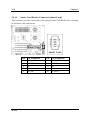
SI-2Pa Dual Socket 604 Server Board User’s Manual 4200-0327-02 Rev. 1.00 Copyright and Warranty Notice The information in this document is subject to change without notice and does not represent a commitment on part of the vendor, who assumes no liability or responsibility for any errors that may appear in this manual. No warranty or representation, either expressed or implied, is made with respect to the quality, accuracy or fitness for any particular part of this document. In no event shall the manufacturer be liable for direct, indirect, special, incidental or consequential damages arising from any defect or error in this manual or product. Product names appearing in this manual are for identification purpose only and trademarks and product names or brand names appearing in this document are property of their respective owners. This document contains materials protected under International Copyright Laws. All rights reserved. No part of this manual may be reproduced, transmitted or transcribed without the expressed written permission of the manufacturer and authors of this manual. SI-2Pa Table Of Contents Chapter 1. 1.1. 1.2. 1.3. Chapter 2. 2.1. 2.2. 2.3. 2.4. 2.5. Introduction .................................................... 1-1 Features & Specifications....................................................... 1-1 Package Checklist (Standard Package) .................................. 1-3 Layout Diagram...................................................................... 1-4 Hardware Setup.............................................. 2-1 Precautions ............................................................................. 2-1 Installing the Server Board..................................................... 2-2 Installing the CPU .................................................................. 2-3 2.3.1. Installing Retention Modules.................................... 2-3 2.3.2. Installing CPU into Socket ....................................... 2-4 2.3.3. Installing Heatsink and Wind Tunnel....................... 2-4 2.3.4. Installing Fan to Wind Tunnel Assembly................. 2-5 System Memory ..................................................................... 2-6 2.4.1. Memory Configuration Table ................................... 2-6 2.4.2. Installing and Removing Memory Modules............. 2-6 Connectors, Headers, and Switches ....................................... 2-8 2.5.1. EPS12V Power Connectors [J13, J17] ..................... 2-8 2.5.2. FAN Connectors [FAN1~6] ..................................... 2-9 2.5.3. CMOS Memory Clearing Header [CCMOS1] ....... 2-10 2.5.4. Front Panel Switches & Indicators Headers [FPIO1] ................................................................................ 2-11 2.5.5. IDE Connectors [IDE1, IDE2] ............................... 2-12 2.5.6. PCI Expansion Slots [PCI1~PCI6]......................... 2-13 2.5.7. VGA Output Header [VGA1]................................. 2-14 2.5.8. COM Port Header [COM1, COM2] ....................... 2-15 2.5.9. Additional USB Ports Header [USB_2] ................. 2-16 2.5.10. Parallel Port Connector [LPT1] .............................. 2-17 2.5.11. Smart Card Reader Connector [Smart Card].......... 2-18 2.5.12. External I/O Panel Connectors ............................... 2-19 User’s Manual Chapter 3. 3.1. 3.2. 3.3. 3.4. 3.5. 3.6. Chapter 4. 4.1. BIOS Setup...................................................... 3-1 Main Menu ............................................................................. 3-2 Advanced Menu ..................................................................... 3-5 3.2.1. Advanced BIOS Features ......................................... 3-5 3.2.2. Advanced Chipset Features ...................................... 3-8 3.2.3. Integrated Peripherals ............................................. 3-10 3.2.4. Power Management Setup ...................................... 3-13 3.2.5. PnP/PCI Configurations.......................................... 3-15 Security Menu ...................................................................... 3-17 PC Health Menu ................................................................... 3-18 Clk/Misc. Menu.................................................................... 3-19 Exit Menu ............................................................................. 3-20 Driver Installation .......................................... 4-1 Setup Items ............................................................................. 4-2 Appendix A. Trouble Shooting ........................................... A-1 Appendix B. How to Get Technical Support ..................... B-1 SI-2Pa Introduction 1-1 Chapter 1. Introduction 1.1. Features & Specifications CPU • Supports dual Intel Xeon 400MHz/533MHz Processors with 512K L2 Cache Chipset • • • Intel® E7501 Chipset Memory Controller Hub (MCH) 82801CA I/O Controller Hub 3-S (ICH3-S) 82870P2 64-bit PCI/PCI-X Controller Hub 2 (P64H2) Memory • • 4x 184-pin DIMM sockets support 144-bit wide (Dual Channel) PC2100/1600 (DDR266/200) memory Up to 8GB, ECC, Registered memory capacity (Chipkill technology support) LAN • • • 2x Intel 82546EB dual port Gigabit Ethernet Controllers RX and TX IP and TCP/UDP checksum off-loading capabilities Front panel LAN Active/Link LED Graphics • • Onboard ATI RAGE XL PCI interface VGA 4MB local SDRAM memory support System BIOS • • AWARD Plug and Play BIOS supports APM, DMI, and ACPI 4M-bit Flash ROM PCI Extension Slot • • • 1x PCI-X 64bit/100MHz 4x PCI-X 64bit, up to 133MHz max. 1x PCI 32bit/33MHz Internal I/O Connectors • • 2x Channels Bus Master IDE Ports supporting Ultra DMA 33/66/100 1x USB Header User’s Manual 1-2 Chapter 1 • • • • • 2x COM Port Headers 1x LPT Port Header 1x VGA Header 1x Smart Card Reader Header EPS12V PSU Connector External I/O Panel • • • PS/2 Keyboard and PS/2 Mouse Connectors 2x USB Connectors 4x RJ-45 LAN ports Form Factor • SI-2Pa EEB 3.0 Form Factor: 12in. x 13in. (305mm x 330mm) Specifications and information contained herein are subject to change without notice. Introduction 1-3 1.2. Package Checklist (Standard Package) (1) SI-2Pa Server Board (1) Brief Installation Guide (1) Driver & Utilities CD (1) 34-pin FDD Cable (1) 40-pin IDE ATA66 Cable (1) 26-pin to D-SUB 25-pin Print Port Extension Cable w/Bracket (1) 16-pin to D-SUB 15-pin VGA Port Extension Cable w/Bracket (1) 10-pin to D-SUB 9-pin COM Port Extension Cable w/Bracket (2) 603/604-pin Retention Module (2) 603-pin Retention Module w/Clip (2) 604-pin Retention Module w/Clip (1) I/O Shield User’s Manual 1-4 1.3. Layout Diagram SI-2Pa Chapter 1 Introduction 1-5 Jumpers Description Default Setting CCMOS1 CMOS Clear Pins 1-2 (Normal) Closed Connectors Description COM1/COM2 External COM1 & COM2 Bracket Connectors DIMM 1~4 DDR DIMM Slots FAN1~5 Fan Connectors (Speed monitoring support in BIOS menu) FAN6 Fan Connector (No speed monitoring support in BIOS menu) FPIO1 Front Panel Switches & Indicators Headers IDE1/IDE2 Hard Disk Drive Connectors J13 8-Pin EPS12V Power Connector J17 24-Pin EPS12V Power Connector LPT1 Parallel Port Connector PCI1~5 PCI-X 100MHz/64bit Slot PCI6 PCI 33MHz/32bit Slot Smart Card Smart Card Reader Extension Cable Connector USB_2 Additional USB Ports Connector VGA1 VGA Output Extension Cable Connector User’s Manual 1-6 SI-2Pa Chapter 1 Hardware Setup Chapter 2. 2-1 Hardware Setup 2.1. Precautions Please pay attention to the following precautions before setting up any hardware. 1. Always switch off the power supply and unplug the power cord from the wall outlet before installing the board or changing any settings. 2. Ground yourself properly by wearing a static safety wrist strap before removing the board from the antistatic bag. 3. Hold the board by its edges. Avoid touching any component on it. 4. Avoid touching module contacts and IC chips 5. Place the board on a grounded antistatic surface or on the antistatic bag that came with the board. User’s Manual 2-2 Chapter 2 2.2. Installing the Server Board Before installing the server board, exam your chassis to ensure this server board fits into it. Your chassis should support EEB 3.0 form factor. 1. Face the side of the I/O ports toward the control panel. 2. Locate the screw holes on the server board and the chassis base. 3. Place all the studs or spacers needed on the chassis base and have them tightened. 4. Line up all the screw holes on the board with those studs or spacers on the chassis. 5. Tightens all the screw holes. ATTENTION: To prevent shorting the PCB circuit, please REMOVE the metal studs or spacers if they are already secured on the chassis base and are without mounting-holes on the server board to align with. SI-2Pa Hardware Setup 2-3 2.3. Installing the CPU This server board provides dual 604-pin Zero Insertion Force (ZIF) sockets to install the Intel Xeon CPU. NOTE: This server board also supports the Xeon CPU of 603-pin package. NOTE: This server board supports installing either one or two CPUs. To set up system with only one CPU, you MUST install it in the Primary Processor Socket (Socket CPU0 in this model). To install a second processor, you must verify that the second processor is identical to the first processor of same voltage and speed. Using non-identical processors could cause system failure. 2.3.1. Installing Retention Modules 1. Remove power from your system by unplugging the AC power cord. 2. Remove the chassis cover (see your system or chassis documentation for instructions). 3. Locate the CPU sockets. 4. Insert the retention modules and tighten four retention screws. User’s Manual 2-4 2.3.2. Chapter 2 Installing CPU into Socket 1. Lift the socket lever upright to 115 degree at least. 2. Align the triangle mark on the CPU with the triangle cutout on the CPU socket. 3. Insert the CPU into the socket until it fits in place. Do not use extra force to insert CPU; it only fit in one orientation. Close down the socket lever to its locked position while firmly pressing the CPU. 4. Apply thermal grease to the CPU with an applicator. 2.3.3. Installing Heatsink and Wind Tunnel 1. Align the heatsink with the retention modules, and then place the heatsink onto the CPU. 2. Position the retention clip over the plastic tab and then engage the clip end-slot over the plastic tab. 3. Press downward on the retention clip ends until they engage the plastic tabs. 4. Repeat steps 2-3 to install the other retention clip. 5. Install the CPU wind tunnel center portion over the heatsink. Note that the plastic tabs engage the tabs on the retention clips. SI-2Pa Hardware Setup 2.3.4. 2-5 Installing Fan to Wind Tunnel Assembly 1. Attach the cooling fan with its airflow direction pointed to heatsink to the air intake portion of wind tunnel. 2. Attach the air intake assembly to the side of the wind tunnel nearest to the front of the chassis. Instead of attaching cooling fan to the side of the wind tunnel, the fan itself could also be attached to the top of the center portion of wind tunnel. 3. Align the tabs on the assembly with the slots in the wind tunnel portion, and then snap the lower portion of the fan holder over the tabs on the center portion. 4. Attach the air outlet portion of the wind tunnel. 5. Attach CPU Fan 1 power cable to the server board at location FAN1 and/or attach CPU Fan 2 power cable at location FAN2. NOTE: The system airflow should be toward the front of the chassis. If there are two processors installed, the fans should be positioned side by side. User’s Manual 2-6 Chapter 2 2.4. System Memory This server board provides four 184-pin Double Data Rate (DDR) Dual Inline Memory Module (DIMM) slots for Registered ECC DIMM modules with memory expansion size up to 8GB (DDR266/DDR200). 2.4.1. Memory Configuration Table DIMM Registered ECC DIMM Module Total Memory 1 128MB, 256MB, 512MB, 1GB, 2GB 128MB ~ 2GB 2 128MB, 256MB, 512MB, 1GB, 2GB 128MB ~ 2GB 3 128MB, 256MB, 512MB, 1GB, 2GB 128MB ~ 2GB 4 128MB, 256MB, 512MB, 1GB, 2GB 128MB ~ 2GB Total System Memory 2.4.2. 256MB ~ 8GB Installing and Removing Memory Modules ATTENTION: Populate the DDR DIMMs in-order and in-pair (of the same type and size) by starting from DIMM1+DIMM2 to DIMM3+DIMM4. The system may hang or appear unstable if the DIMM ordering is not followed. SI-2Pa Hardware Setup 2-7 Power off the computer and unplug the AC power cord before installing or removing memory modules. 1. Locate the DIMM slot on the server board. 2. Hold two edges of the DIMM module carefully, keep away of touching its connectors. 3. Align the two notch keys on the module with the two ribs on the slot. 4. Firmly press the module into the slots until the ejector tabs at both sides of the slot automatically snaps into the mounting notch. Do not force the DIMM module in with extra force as the DIMM module only fit in one orientation. 5. To remove the DIMM modules, push the two ejector tabs on the slot outward simultaneously, and then pull out the DIMM module. ATTENTION: As the static electricity can damage the electronic components of the computer or optional modules, make sure you are discharged of static electricity by touching a grounded metal object briefly before starting these procedures. User’s Manual 2-8 Chapter 2 2.5. Connectors, Headers, and Switches All the connectors, headers and switches mentioned here are depending on your system configuration. Some features you may (or may not) have to connect or to configure depending on the peripherals you have connected. WARNING: Always power off the computer and unplug the AC power cord before adding or removing any peripheral or component. Failing to so may cause severe damage to your server board and/or peripherals. Plug in the AC power cord only after you have carefully checked everything. 2.5.1. EPS12V Power Connectors [J13, J17] These two connectors connect to EPS12V power supply. This server board requires an EPS12V power supplier with 460W capacity at least for Pentium 4 Xeon CPU system. WARNING: This server board only supports EPS12V power supplies and will not operate with other types. DO NOT use ATX 2.x, ATX12V and dual AMD power supplies as they will damage the board and void your warranty. NOTE: The auxiliary 12V power (J13) is necessary to support Intel Xeon CPUs. Failing to provide such extra power will result in the system’s booting failure. SI-2Pa Hardware Setup 2.5.2. 2-9 FAN Connectors [FAN1~6] These 3-pin connectors each provide power to the cooling fans installed in your system. The CPU must be kept cool by using a powerful fan with heatsink. The system is capable of monitoring the speed of the CPU fan. • FAN1~FAN5: With speed monitoring support in BIOS menu • FAN6: Without speed monitoring support in BIOS menu WARNING: These fan connectors are not jumpers. DO NOT place jumper caps on these connectors. User’s Manual 2-10 2.5.3. Chapter 2 CMOS Memory Clearing Header [CCMOS1] This header uses a jumper cap to clear the CMOS memory. • Pin 1-2 shorted (default): Normal operation. • Pin 2-3 shorted: Clear CMOS memory. ATTENTION: Turn the system power off first (including the +5V standby power) before clearing the CMOS memory. Failing to do so may cause your system to work abnormally or malfunction. SI-2Pa Hardware Setup 2.5.4. 2-11 Front Panel Switches & Indicators Headers [FPIO1] This header is used for connecting switches and LED indicators on the chassis front panel. Watch the power LED pin position and orientation. The mark “+” align to the pin in the figure below stands for positive polarity for the LED connection. Pin Number Pin Assignment Pin 1, 2 POW-ON Pin 3, 4 RESET Pin 5, 6 CASE Pin 7, 8 PWR-LED Pin 9, 10 HDD-LED Pin 13, 14 NIC1 Pin 15, 16 NIC2 Pin 17, 18 NIC3 Pin 19, 20 NIC4 Definition Connects to the Power Switch cable of chassis front panel. Connects to the Reset Switch cable of chassis front panel. Case-Open Detection Header Connects to the Power LED cable of chassis front panel. Connects to the HDD LED cable of chassis front panel. Network Interface Controller 1 Active/Link Indicator Network Interface Controller 2 Active/Link Indicator Network Interface Controller 3 Active/Link Indicator Network Interface Controller 4 Active/Link Indicator User’s Manual 2-12 2.5.5. Chapter 2 IDE Connectors [IDE1, IDE2] Each of the IDE port connects up to two IDE drives at Ultra ATA/100 mode by one 40-pin, 80-conductor, and 3-connector Ultra ATA/66 ribbon cables. Connect the single end (blue connector) at the longer length of ribbon cable to the IDE port of this board, the other two ends (gray and black connector) at the shorter length of the ribbon cable to the connectors of your hard drives. NOTE: Make sure to configure the “Master” and “Slave” relation before connecting two drives by one single ribbon cable. The red line on the ribbon cable must be aligned with pin-1 on both the IDE port and the hard-drive connector. SI-2Pa Hardware Setup 2.5.6. 2-13 PCI Expansion Slots [PCI1~PCI6] PCI1: Supports PCI-X 64bit/100MHz. PCI2~PCI5: These four slots support the speed of 66MHz, 100MHz, or 133MHz, according to the number of how many slots are occupied. • 1 slot occupied: PCI-X 64bit/133MHz. • 2 ~ 3 slots occupied: PCI-X 64bit/100MHz. • 4 slots occupied: PCI-X 64bit/66MHz. PCI6: Supports PCI 32bit/33MHz. User’s Manual 2-14 2.5.7. Chapter 2 VGA Output Header [VGA1] This header provides connection to external VGA Port through an extension cable and bracket. SI-2Pa Hardware Setup 2.5.8. 2-15 COM Port Header [COM1, COM2] These two headers each provide connection to external COM Ports through an extension cables and brackets. User’s Manual 2-16 2.5.9. Chapter 2 Additional USB Ports Header [USB_2] This header provides two additional USB ports connection through an extension cable and bracket. Pin 1 3 5 7 SI-2Pa Pin Assignment VCC Data0 Data0 + Ground Pin 2 4 6 8 10 Pin Assignment VCC Data1 Data1 + Ground NC Hardware Setup 2.5.10. 2-17 Parallel Port Connector [LPT1] This connector provides connection to external Parallel Port through an extension cable and bracket. User’s Manual 2-18 2.5.11. Chapter 2 Smart Card Reader Connector [Smart Card] This connector provides connection to the optional Smart Card Reader device through an extension cable and bracket. Pin 1 3 5 7 9 SI-2Pa Pin Assignment VCC SCPWR NC SCIO SCCLK Pin 2 4 6 8 10 Pin Assignment GND SCRST NC NC SCPSNT Hardware Setup 2.5.12. 2-19 External I/O Panel Connectors • Mouse: PS/2 mouse connector. • Keyboard: PS/2 keyboard connector. • USB1: Universal Serial Bus connector • LAN1/LAN2: Local Area Network connector. User’s Manual 2-20 SI-2Pa Chapter 2 BIOS Setup Chapter 3. 3-1 BIOS Setup This motherboard provides a programmable EEPROM that you can update the BIOS utility. The BIOS (Basic Input/Output System) is a program that deals with the basic level of communication between processor and peripherals. Use the BIOS Setup program only when installing motherboard, reconfiguring system, or prompted to “Run Setup”. This chapter explains the Setup Utility of BIOS utility. After powering up the system, the BIOS message appears on the screen, the memory count begins, and then the following message appears on the screen: Press DEL to run setup If this message disappears before you respond, restart the system by pressing <Ctrl> + <Alt> + <Del> keys, or by pressing the Reset button on computer chassis. Only when it failed by these two methods can you restart the system by powering it off and then back on. NOTE: In order to increase system stability and performance, our engineering staffs are constantly improving the BIOS menu. The BIOS setup screens and descriptions illustrated in this manual are for your reference only, may not completely match what you see on your screen. After pressing <Del> key, the main menu screen appears. User’s Manual 3-2 Chapter 3 3.1. Main Menu Date (mm:dd:yy) This item sets the date you specify (usually the current date) in the format of [Month], [Date], and [Year]. Time (hh:mm:ss) This item sets the time you specify (usually the current time) in the format of [Hour], [Minute], and [Second]. IDE Primary Master, IDE Primary Slave, IDE Secondary Master, and IDE Secondary Slave Move cursor to item “IDE Primary Master”, “IDE Primary Slave”, “IDE Secondary Master” or “IDE Secondary Slave”, and then press <Enter> key to enter a sub-menu. SI-2Pa BIOS Setup 3-3 IDE Primary/Secondary Master/Slave IDE HDD Auto-Detection This item allows you to detect the parameters of IDE drives by pressing <Enter> key. The parameters will be shown on the screen automatically. IDE Primary Master When set to [Auto], the BIOS will automatically check what kind of IDE drive you are using. If you want to define your own drive by yourself, set it to [Manual] and make sure you fully understand the meaning of the parameters. Refer to the manual provided by the device manufacturer to get the settings right. Access Mode This item selects the mode to access your IDE devices. Leave this item to its default [Auto] settings to let BIOS detects the access mode of your HDD and makes decision automatically. Capacity This item displays the approximate capacity of the disk drive. Usually the size is slightly greater than the size of a formatted disk given by a disk-checking program. NOTE: The following [Cylinder], [Head], [Precomp], [Landing Zone], and [Sector] items are available when you set the item “IDE Primary Master” to “Manual”. User’s Manual 3-4 Chapter 3 Cylinder This item configures the numbers of cylinders. Head This item configures the numbers of read/write heads. Precomp This item displays the number of cylinders at which to change the write timing. Landing Zone This item displays the number of cylinders specified as the landing zone for the read/write heads. Sector This item configures the numbers of sectors per track. Halt On This item determines whether the system stops if an error is detected during system boot-up. [All Errors]: The system-boot will stop whenever the BIOS detect a non-fatal error. [No Errors]: The system-boot will not stop for any error detected. [All, But Keyboard]: The system-boot will stop for all errors except a keyboard error. [All, But Diskette]: The system-boot will stop for all errors except a diskette error. [All, But Disk/Key]: The system-boot will stop for all errors except a diskette or keyboard error. Base Memory This item displays the amount of base memory installed in the system. The value of the base memory is typically 640K for system with 640K or more memory size installed on the motherboard. Extended Memory This item displays the amount of extended memory detected during system boot-up. Total Memory This item displays the total memory available in the system. SI-2Pa BIOS Setup 3-5 3.2. Advanced Menu 3.2.1. Advanced BIOS Features User’s Manual 3-6 Chapter 3 CPU Hyper-Threading This option enables or disables the processor’s Hyper-Threading Technology. Leave this item to its default setting to enable the simultaneous multi-threaded (SMT) processor so as to make one physical processor looks like two logical processors to the OS and applications. This option is for CPU with Hyper-Threading Technology only. For more information on “Hyper-Threading Technology”, please visit Intel Web site at http://www.intel.com/homepage/land/hyperthreading.htm , http://www.intel.com/design/chipsets/ht/. Quick Power On Self Test When set to [Enabled], this item speeds up the Power On Self Test (POST) after powering on the system. The BIOS shorten or skip some check during the POST. Hard Disk Boot Priority This item selects the hard disks booting priority. By pressing <Enter> key, you can enter its submenu where the hard disks detected can be selected for the booting sequence to boot up system. This item functions only when there is the option of [Hard Disk] in any one of the First/Second/Third Boot Device items. First Boot Device / Second Boot Device / Third Boot Device / Boot Other Device Select the drive to boot first, second and third in the [First Boot Device], [Second Boot Device], and [Third Boot Device] fields respectively. The BIOS will boot the operating system according to the sequence of the drive selected. Set [Boot Other Device] to [Enabled] if you wish to boot from another device other than these three items. Boot Up NumLock Status This item determines the default state of the numeric keypad at system booting up. [On]: The numeric keypad functions as number keys. [Off]: The numeric keypad functions as arrow keys. Security Option This item determines when the system will prompt for password - every time the system boots or only when enters the BIOS setup. SI-2Pa BIOS Setup 3-7 [Setup]: The password is required only when accessing the BIOS Setup. [System]: The password is required each time the computer boots up. NOTE: Don’t forget your password. If you forget the password, you will have to open the computer case and clear all information in the CMOS before you can start up the system. But by doing this, you will have to reset all previously set options. MPS Version Control For OS This item specifies which version of MPS (Multi-Processor Specification) this server board will use. The options are 1.1 and 1.4. The default setting is 1.4. If you use an older OS for dual processor executing, please set this option to 1.1. Small Logo(EPA) Show This item determines to show the EPA logo when booting. User’s Manual 3-8 3.2.2. Chapter 3 Advanced Chipset Features DRAM Timing Control This item controls the DRAM timing. Press <Enter> key to enter its menu. Memory Type This item displays the type of memory module you are using. SI-2Pa BIOS Setup 3-9 Memory Frequency This item displays the frequency of memory module you are using. DRAM Timing Selectable This item sets the optimal timings for the following four items, depending on the memory module you are using. The default setting “By SPD” configures these four items by reading the contents in the SPD (Serial Presence Detect) device. The EEPROM on the memory module stores critical parameter information about the module, such as memory type, size, speed, voltage interface, and module banks. CAS Latency Time This item controls the latency between the DRAM read command and the time that the data becomes actually available. Active to Precharge Delay This item controls the number of DRAM clocks used for DRAM parameters. DRAM RAS# to CAS# Delay This item controls the latency between the DRAM active command and the read/write command. DRAM RAS# Precharge This item controls the idle clocks after issuing a precharge command to the DRAM. Delayed Transaction When set to [Enabled], the PCI bus will be freed up when the CPU is accessing 8-bit ISA cards. This will allow PCI and ISA buses to be used more efficiently and prevents performance dropping on the PCI bus. This process normally consumes about 50-60 PCI clocks without PCI delayed transaction. Leave this item to its default [Disabled] setting when using ISA cards that are not PCI 2.1 compliant. User’s Manual 3-10 3.2.3. Chapter 3 Integrated Peripherals Onboard IDE-1 Controller This item enables or disables the onboard IDE-1 controller. Onboard IDE-2 Controller This item enables or disables the onboard IDE-2 controller. USB Controller This option enables or disables the USB controller. USB Keyboard Support This item allows you to select [BIOS] for using USB keyboard in DOS environment, or [OS] in OS environment. USB Mouse Support This item allows you to select [BIOS] for using USB mouse in DOS environment, or [OS] in OS environment. Onboard LAN1 Controller This item enables or disables the onboard LAN1 controller. SI-2Pa BIOS Setup 3-11 Onboard LAN Boot ROM This item allows you to use the boot ROM (instead of a disk drive) to boot-up the system and access the local area network directly. Onboard LAN2 Controller This item enables or disables the onboard LAN2 controller. Onboard LAN Boot ROM This item allows you to use the boot ROM (instead of a disk drive) to boot-up the system and access the local area network directly. Onboard Serial Port 1 This item determines which I/O addresses the onboard Serial Port 1 controller will access. [Auto]: The system automatically select an I/O address for the onboard Serial Port 1. [3F8/COM1, 2F8/COM2, 3E8/COM3, 2E8/COM4]: Allows you to manually select an I/O address for the onboard Serial Port 1. [Disabled]: Disables the onboard Serial Port 1. Onboard Serial Port 2 This item determines which I/O addresses the onboard Serial Port 2 controller will access. [Auto]: The system automatically select an I/O address for the onboard Serial Port 2. [3F8/COM1, 2F8/COM2, 3E8/COM3, 2E8/COM4]: Allows you to manually select an I/O address for the onboard Serial Port 2. [Disabled]: Disables the onboard Serial Port 2. Onboard Parallel Port This item specifies the I/O address used by the parallel port. [Disabled]: This option prevents the parallel port from accessing any system resources. When the value of this option is set to [Disabled], the printer port becomes unavailable. [378]: This option allows the parallel port to use [378] as its I/O port address. The majority of parallel ports on computer systems use IRQ7 and I/O Port 378H as the standard setting. [278]: This option allows the parallel port to use [278] as its I/O port address. User’s Manual 3-12 Chapter 3 [3BC]: This option allows the parallel port to use [3BC] as its I/O port address. Parallel Port Mode This item specifies the parallel port mode. [SPP]: (Standard Parallel Port) Allows bi-directional parallel port operation at normal speed. [EPP]: (Enhanced Parallel Port) Allows bi-directional parallel port operation at maximum speed. [ECP]: (Extended Capabilities Port) Allows bi-directional parallel port operation at a speed faster than the normal mode’s data transfer rate. [EPP+ECP]: Using parallel port as EPP & ECP mode. EPP Mode Select This item selects the EPP mode. ECP Mode Use DMA This item selects the DMA channel of the parallel port. PWRON After PWR-Fail This item sets the system action after a power failure. SCR Port Address This item sets the I/O address and IRQ of the onboard SCR (Smart Card Reader) port. SCR Port IRQ After enabling the SCR port, here you can set the IRQ for SCR port. SI-2Pa BIOS Setup 3.2.4. 3-13 Power Management Setup Soft-Off by PWR-BTTN This item selects the method of powering off your system: [Hold 4 Sec.]: Pushing the power button for more than 4 seconds will power off the system. This will prevent the system from powering off in case you accidentally hit or pushed the power button. [Instant-Off]: Pressing and then releasing the power button at once will immediately power off the system. Wake-Up by PCI card/LAN When set to [Enabled], access to the onboard LAN or a PCI card such as a modem or LAN card will cause the system to wake up. The PCI card must support the wake up function. Resume by Alarm When set to [Enabled], you can set the date and time you would like the Soft-Off PC to power-on in the “Date (of Month) Alarm” and “Time (hh:mm:ss) Alarm” items. However, if the system is being accessed by incoming calls or the network (Resume On Ring/LAN) prior to the date and time set in these items, the system will give priority to the incoming calls or network instead. User’s Manual 3-14 Chapter 3 Date (of Month) Alarm [0]: This option power-on the system everyday according to the time set in the “Time (hh:mm:ss) Alarm” item. [1-31]: This option selects a date you would like the system to power-on. The system will power-on on the date set, and the time set in the “Time (hh:mm:ss) Alarm” item. Time (hh:mm:ss) Alarm This item sets the time you would like the system to power-on. SI-2Pa BIOS Setup 3.2.5. 3-15 PnP/PCI Configurations Force Update ESCD When set to [Enabled], the BIOS will reset the ESCD (Extended System Configuration Data) once automatically next time you boot up. It will then recreate a new set of configuration data. But the next time you boot up, this option will automatically be set as Disabled. Resources Controlled By This item configures all of the boot and Plug-and-Play compatible devices. [Auto(ESCD)]: The system will automatically detect the settings. [Manual]: Choose the specific IRQ resources in the “IRQ Resources” menu. IRQ Resources Click <Enter> key to enter its submenu: This item sets each system interrupt to either [PCI Device] or [Reserved]. User’s Manual 3-16 SI-2Pa Chapter 3 BIOS Setup 3-17 3.3. Security Menu Set Supervisor Password This option protects the BIOS configuration or restricts access to the computer itself. The Supervisor Password is used to protect the stored CMOS options from being changed by unauthorized users. Set User Password This option protects the BIOS configuration or restricts access to the computer itself. The User Password requires all users to enter a password in order to use the system, and/or enter the BIOS setup (but can’t change its contents). User’s Manual 3-18 Chapter 3 3.4. PC Health Menu Shutdown Temperature This item sets the temperature that would shutdown the system automatically in order to prevent system overheats. CPU Warning Temperature This item selects the CPU’s warning temperature limit. Once the system has detected that the CPU’s temperature exceeded the limit, warning beeps will sound. NOTE: The onboard hardware monitor function is capable of detecting these system health conditions. If you want a warning message to pop-up or a warning alarm to sound when an abnormal condition occurs, you must install the “Hardware Doctor” utility. This utility is included in the “Driver & Utility CD” that came packed with this motherboard. All Voltages, Fans Speed and Thermal Monitoring These unchangeable items list the current status of the CPU and environment temperatures, fan speeds, and system power voltage. NOTE: The hardware monitoring features for temperatures, fans and voltages will occupy the I/O address from 294H to 297H. If you have a network adapter, sound card or other add-on cards that might use those I/O addresses, please adjust your add-on card I/O address to avoid using these addresses. SI-2Pa BIOS Setup 3-19 3.5. Clk/Misc. Menu CPU Clock Ratio This option selects the CPU clock ratio. Please type in the correct multiple for your CPU. Case-Open Detection This option controls the function for case-opening detection via the “CASE” header on FPIO1 header. BIOS Protect Control This option protects for accidentally BIOS writing attempt. NOTE: Make sure to set this item to “Unprotected” when flashing the BIOS. User’s Manual 3-20 Chapter 3 3.6. Exit Menu Once you have made all your selections in the previous BIOS setup menu, you have to save the settings and exit the setup menu. Select the Exit Menu in the menu bar to show the following menu: NOTE: Pressing <ESC> does not exit this menu. You have to select one of the options in this menu, such as “Exit Without Saving” to exit the menu without saving your previous settings. Load Fail-Safe Defaults This option loads the BIOS default values for the most stable, minimal-performance system operations. Load Optimized Defaults This option loads the BIOS default values that are factory settings for optimal-performance system operations. Save & Exit Setup This option saves your selections and exits the setup menu. Exit Without Saving This option exits the setup menu without saving any change. SI-2Pa Driver Installation Chapter 4. 4-1 Driver Installation All the necessary drivers are included within the Drivers & Utilities CD that came packaged with your board. The display shown in the following figure should appear after inserting this CD into your CD-ROM drive, if not, enter [My Computer] [CD-ROM] Drive double click [Launch]. Please follow the on-screen instruction. NOTE: The Support CD contents are subject to change at any time without notice. Please follow the on-screen instructions to complete the installation. After installing each item, you must reboot the system before moving on to the next item on the list. User’s Manual 4-2 Chapter 4 4.1. Setup Items • Intel Chipset Software Utility Install Intel chipset driver for Windows Operating System. • ATI VGA Driver Install ATI VGA graphic driver for Windows Operating System. • Intel LAN Driver Install the drivers needed to run Fast Ethernet controller. The operating systems supported are Windows, Windows XP 64-bit, Linux, Netware, and FreeBSD. • Manual View the user’s manual in PDF. • Utility Click to enter the sub-screen for installing software like Acrobat Reader, Award Flash, DirectX8.1, and LoFormat Utility. • Hardware Doctor Install the Hardware Doctor program for monitoring the system health. • Browse CD Browse the contents of this CD-ROM. • Close Exit the CD setup Items Menu. SI-2Pa Trouble Shooting A-1 Appendix A. Trouble Shooting Why the system shows incorrect CPU speed in Win2K If you run Msinfo32.exe on a computer that has an Intel Pentium 4 Xeon 2.2-GHz or faster processor, a very high processor speed may be shown. The Processor information on the System Summary page shows the correct name, family, model and stepping for the processor, but the approximate speed may be 37,000 MHz or faster. This is because the speed of the newest Pentium processors exposes a limitation in the speed calculation code in Msinfo32.exe. To resolve this problem, refer to the hotfix described in the Microsoft Knowledge Base article: “Q302857 WMI Win32_Group ASSOCIATORS Queries Are Not Optimized”. User’s Manual A-2 Appendix A How to improve system performance for RedHat 7.2 and RedHat 7.3 It is recommended to upgrade RedHat 7.2 to version 7.3, since there are many improvements as well as kernel upgrade. Currently there is limitation about multi-processor handling irq in RedHat 7.3. It is suggested to download the latest kernel in order to improve the performance. The latest kernel 2.4.18 need patch to fix multi-processor handle irq limitation. Please use the following steps to build the kernel. Download the latest kernel from http://www.kernel.org, for example: linux-2.4.18.tar.gz . # mv linux-2.4.18.tar.gz /usr/src # gunzip linux-2.4.18.tar.gz (unpack the kernel) # tar xvf linux-2.4.18.tar (extract form kernel tar file) # patch -p0 < irq.patch (update necessary patch) # cd linux # make mrproper # make xconfig # make dep # make clean # make bzImage # cp /usr/src/linux/arch/i386/boot/bzImage /boot/vmlinuz-24188irqbal # make modules # make modules_install # mkdinitrd /boot/initrd.2.4.18.img 2.4.18 # cp /usr/src/linux/System.map /boot/System.map-2.4.18-irqbal # cd /boot # ln -s System.map-2.4.18-irqbal System.map # add following entries to /etc/lilo.conf image=/boot/vmlinuz-24188irqbal label=lin24188irqbal initrd=/boot/initrd-2.4.18.img read-only root=/dev/hda2 # lilo # reboot SI-2Pa Trouble Shooting A-3 How to access system memory in excess of 4GB for Microsoft Windows 2000 Advanced Server and Datacenter Server Microsoft Windows 2000 Advanced Server and Datacenter Server support memory in excess of 4GB of RAM by way of the Intel Physical Addressing Extension (PAE) specification. Windows 2000 Advanced Server is limited to 8GB, and Windows 2000 Datacenter Server is limited to 64GB. You can enable PAE in the “Boot.ini” file. To enable PAE, follow these steps: 1. Locate the Boot.ini file, typically in the root folder (for example, C:) and remove its read-only attribute. 2. Open the Boot.ini file, and then add the /PAE parameter to the ARC path, as shown in bold format in the following example: multi(0)disk(0)rdisk(0)partition(2)\WINNT= “Windows 2000 Advanced Server” /PAE /basevideo /sos 3. On the File menu, click Save. 4. Restore the read-only attribute to the Boot.ini file. Even with PAE enabled, the underlying architecture of the system is still based on 32-bit linear addresses. This effectively retains the 2GB of application space and the 2GB of kernel mode space because only 4GB of addresses are available. However, multiple processes can immediately benefit from the increased RAM because they are less likely to encounter physical memory restrictions and begin paging. Additionally, applications can be modified to use the AWE API to allocate memory outside of the applications process space, bypassing the 2-GB limit for applications. User’s Manual A-4 SI-2Pa Appendix A How to Get Technical Support B-1 Appendix B. How to Get Technical Support (From our website) http://www.abit.com.tw (In North America) http://www.abit-usa.com (In Europe) http://www.abit.nl Thank you for choosing ABIT products. ABIT sells all our products through distributors, resellers and system integrators; we have no direct sales to end-users. Before sending email for tech support please check with your resellers or integrators if you need any services, they are the ones who sold you your system and they should know best as to what can be done, how they serve you is a good reference for future purchases. We appreciate every customer and would like to provide the best service to you. Providing fast service to our customers is our top priority. However we receive many phone calls and a huge amount of email from all over the world. At the present time it is impossible for us to respond to every single inquiry. Therefore it is quite possible that if you send an email to us that you may not receive a response. We have done many compatibility tests and reliability tests to make sure our products have the best quality and compatibility. In case you need service or technical support, please understand the constraint we have and always check with the reseller who sold the product to you first. To expedite service, we recommend that you follow the procedures outlined below before contacting us. With your help, we can meet our commitment to provide the best service to the greatest number of ABIT customers: 1. Check the Manual. It sounds simple but we have taken a lot of care in making a well-written and thorough manual. It is full of information that doesn't only pertain to motherboards. The CD-ROM included with your board will have the manual as well as drivers. If you don't have either one, go to our Program Download Area of the Website or FTP workstation. 2. Download latest BIOS, software or drivers. Please go to our Program Download area on our Website to check to see if you have the latest BIOS. They are developed over periods of time to fixes bugs or incompatibilities. Also please make sure you have the latest drivers from your peripheral cards makers! 3. Check the ABIT Technical Terms Guide and FAQ on our Website. We are trying to expand and make the FAQs more helpful and information rich. Let us know if you have any suggestions. For hot topics check out our HOT FAQ! User’s Manual B-2 Appendix B 4. Internet Newsgroups. They are a great source of information and many people there can offer help. ABIT's Internet News group, alt.comp.periphs.mainboard.abit, is an ideal forum for the public to exchange information and discuss experiences they have had with ABIT products. Many times you will see that your question has already been asked before. This is a public Internet news group and it is reserved for free discussions. Here is a list of some of the more popular ones: alt.comp.periphs.mainboard.abit comp.sys.ibm.pc.hardware.chips alt.comp.hardware.overclocking alt.comp.hardware.homebuilt alt.comp.hardware.pc-homebuilt 5. Ask your reseller. Your ABIT authorized distributor should be able to provide the fastest solution to your technical problem. We sell our products through distributors who sell to resellers and stores. Your reseller should be very familiar with your system configuration and should be able to solve your problem much more efficiently than we could. After all, your reseller regards you as an important customer who may purchase more products and who can urge your friends to buy from him or her as well. They integrated and sold the system to you. They should know best what your system configuration is and your problem. They should have reasonable return or refund policies. How they serve you is also a good reference for your next purchase. 6. Contacting ABIT. If you feel that you need to contact ABIT directly you can send email to the ABIT technical support department. First, please contact the support team for the branch office closest to you. They will be more familiar with local conditions and problems and will have better insight as to which resellers offer what products and services. Due to the huge number of emails coming in every day and other reasons, such as the time required for problem reproduction, we will not be able to reply to every email. Please understand that we are selling through distribution channels and don't have the resources to serve every end-user. However, we will try to do our best to help every customer. Please also remember that for many of our technical support team English is a second language, you will have a better chance of getting a helpful answer if your question can be understood in the first place. Be sure to use very, simple, concise language that clearly states the problem, avoid rambling or flowery language and always list your system components. Here is the contact information for our branch offices: SI-2Pa How to Get Technical Support B-3 North America and South America: ABIT Computer (U.S.A.) Corporation 45531 Northport Loop West, Fremont, California 94538, U.S.A. Tel: 1-510-623-0500 Fax: 1-510-623-1092 [email protected] [email protected] http://www.abit-usa.com U.K. and Ireland: ABIT Computer (U.K.) Corporation Ltd. Unit 3, 24-26 Boulton Road, Stevenage, Herts SG1 4QX, U.K. Tel: 44-1438-228888 Fax: 44-1438-226333 [email protected] [email protected] Germany, Benelux (Belgium, Netherlands, Luxembourg), Denmark, Norway, Sweden, Finland, and Switzerland: AMOR Computer B.V. (ABIT’s European Office) Van Coehoornstraat 7, 5916 PH Venlo, The Netherlands Tel: 31-77-3204428 Fax: 31-77-3204420 [email protected] [email protected] http://www.abit.nl Austria, Czech, Romania, Bulgaria, Yugoslavia, Slovakia, Slovenia, Croatia, Bosnia, Serbia, and Macedonia: Asguard Computer Ges.m.b.H Schmalbachstrasse 5, A-2201 Gerasdorf/Wien, Austria Tel: 43-1-7346709 Fax: 43-1-7346713 [email protected] User’s Manual B-4 Appendix B Japan: ABIT Computer (Japan) Co. Ltd. Fax: 81-3-5396-5110 http://www.abit4u.jp Shanghai: ABIT Computer (Shanghai) Co. Ltd. Tel: 86-21-6235-1829 Fax: 86-21-6235-1832 http://www.abit.com.cn Russia: ABIT Computer (Russia) Co. Ltd. Fax: 7-095-937-2837 [email protected] http://www.abit.ru France, Italy, Spain, Portugal, and Greece: ABIT Computer France SARL Tel: 33-1-5858-0043 Fax: 33-1-5858-0047 http://www.abit.fr All other territories not covered above please contact Taiwan Head Office: When contacting our headquarters please Note we are located in Taiwan and we are 8+ GMT time. In addition, we have holidays that may be different from those in your country. ABIT Computer Corporation No.323, Yang Guang St., Neihu, Taipei, 114, Taiwan Tel: 886-2-8751-8888 Fax: 886-2-8751-3382 [email protected] [email protected] [email protected] http://www.abit.com.tw SI-2Pa How to Get Technical Support B-5 7. RMA Service. If your system has been working but it just stopped, but you have not installed any new software or hardware recently, it is likely that you have a defective component. Please contact the reseller from whom you bought the product. You should be able to get RMA service there. 8. Reporting Compatibility Problems to ABIT. Because of tremendous number of email messages we receive every day, we are forced to give greater weight to certain types of messages than to others. For this reason, any compatibility problem that is reported to us, giving detailed system configuration information and error symptoms will receive the highest priority. For the other questions, we regret that we may not be able to reply directly. But your questions may be posted to the Internet news group in order that a larger number of users can have the benefit of the information. Please check the news group from time to time. Thank You ABIT Computer Corporation http://www.abit.com.tw User’s Manual B-6 Appendix B Technical Support Form Company Name: Phone Number: Contact Person: Fax Number: E-mail Address: Model * Motherboard Model No. BIOS ID # DRIVER REV OS/Application * Hardware Name Brand Specifications CPU HDD CD-ROM-Drive System Memory ADD-ON CARD Problem Description: SI-2Pa * IDE1 IDE2 IDE1 IDE2 *