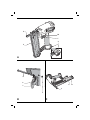
1
ENGLISH
• Do not drive fasteners on top of other fasteners.
• Only use spare parts specified by the
manufacturer or his authorised agents.
• Have repairs carried out only by the manufacturer
or authorised agents having due regard to the
information given in the manual and using the
appropriate tools and equipment.
• Do not disassemble or block any parts of the
fastener driving tool such as the safety yoke.
• Have the tool serviced properly and at regular
intervals.
The following pictograms are shown on the tool:
Read instruction manual before use.
Wear ear protection.
Wear eye protection.
• Check for damage to the tool, parts or accessories
which may have occurred during transport.
• Take the time to thoroughly read and understand
this manual prior to operation.
Description (fig. A)
Your nailer D51238 has been designed for driving
fasteners into wooden workpieces.
1 Trigger/lock-off switch
2 Air fitting
3 Contact trip
4 Magazine
Assembly and adjustment
Do not use on a ladder.
Trigger selection
These tools are assembled with a bump action
trigger. A sequential action trigger is also included
with the original packaging. For definitions of “bump
action” and “sequential action”, see below.
– The grey trigger with a single nail printed on the
side is the sequential action trigger. Installation of
this kit causes the tool to function in sequential
action mode.
– The black trigger with three nails printed on the
side is the bump action trigger. Installation of this
kit causes the tool to function in bump action
mode.
Maximum number of nails in magazine.
Nail diameter.
1.2 mm
Nail length.
Max. operating pressure.
DATE CODE POSITION (FIG. A)
The Date Code (16), which also includes the year of
manufacture, is printed into the housing.
Example:
2010 XX XX
Year of Manufacture
22
The package contains:
1 Nailer
1 Sequential action trigger
1 Pair of safety glasses
1 Allen key
1 Kitbox
1 Instruction manual
Pneumatic tool with safety yoke.
Magazine angle.
16-50 mm
Package contents
Removing the trigger (fig. B)
• Disconnect the airline from the tool.
• Remove all nails from the magazine.
• Remove the rubber grommet (5) from the end of
the dowel pin (6).
• Remove the dowel pin.
• Remove the trigger assembly (7).
Fitting the trigger (fig. B)
• Select the appropriate trigger.
• Insert the trigger assembly into the trigger cavity,