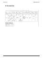
1
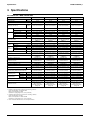
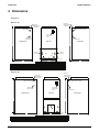
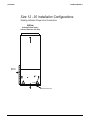
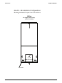
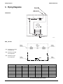
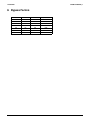
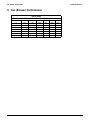
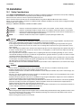
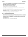
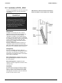
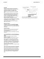
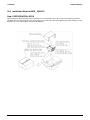
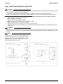
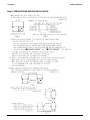
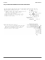
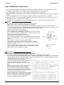
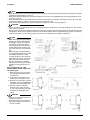
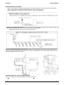
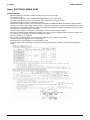
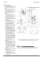
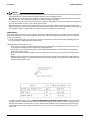
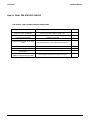
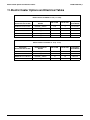
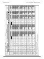
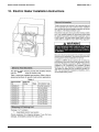
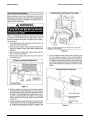
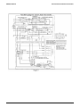
DACA EDUS39-600-F20_b
FXOQ-M + BEQ-M
Concealed Vertical
Air-Handler Type
AMERICAS
1645 Wallace Drive, Suite 110
Carrollton, TX75006
[email protected]
www.daikinac.com
EDUS39-600-F5
Printed in U.S.A. 09/2006 K AK·FS
AMERICAS
FXOQ-M+BEQ-M
Concealed Vertical Air-Handler Type
1. Features.......................................................................................... 2
1.1 Concealed Vertical Air-Handler Features ................................. 2
1.2 Rules for Use with VRV Systems .............................................. 2
1.3 BEQ Junction Box Application Rules ...................................... 2
2. Nomenclature and Combination .................................................... 3
2.1 Nomenclature ........................................................................... 3
2.2 Combination ............................................................................. 4
3. Specifications.................................................................................. 5
4. Dimensions ..................................................................................... 7
5. Piping Diagrams ............................................................................. 11
6. Wiring Diagrams ............................................................................. 12
7. Electric Characteristics ................................................................... 15
8. Bypass Factors ............................................................................... 16
9. Fan (Blower) Performance.............................................................. 17
10. Installation..................................................................................... 18
10.1 Safety Considerations .......................................................... 18
10.2 Installation of FXOQ__MVJU ............................................... 20
10.3 Installation Steps for BEQ__MVJLR1.................................... 22
11. Electric Heater Options and Electrical Tables ............................. 37
12. Electric Heater Installation Instructions........................................ 40
13. Accessories .................................................................................. 44
1
FXOQ-M
EDUS39-600-F20_b
Features
1. Features
1.1
Concealed Vertical Air-Handler Features
Designed for use with R-410A
Rifled copper tubing
Patented Fin Design
UL Listed
Available voltage: 208/60Hz-1ph
High efficiency motors
40 VA control voltage transformer
Dynamically balanced blowers for quiet vibration-free operation
Refrigerant connections are 3/8” ODF liquid and 3/4” ODF (12-30) or 7/8” ODF (36-48) suction.
Dual 3/4” FPT condensate drains
Drain pans are molded of corrosion-proof engineering polymer.
Filter rack built into every air handler
Electric heat is available by a kit for field installation. Plug-in connections simplify installation of kits.
Cabinet constructed of pre-painted heavy gauge galvanized steel to prevent corrosion. Lined with high quality 5/8” foil-faced
insulation to protect sweating.
Available in upflow configuration only.
Standard factory-installed circuit breaker on models with electric heat kits.
All field-installed kits come with thorough, easy to follow instructions.
All air handlers are top-handling packaged with bar coding and full description on the label.
Electrical connections can be made on top or right side.
All coils are individually pressure tested at 500 PSI, then pressurized and sealed.
Magnetic filter rack doors:
Easy filter replacement.
Tight seal for less air leakage.
Fiberglass air filter comes with every air handler.
Filter rack accepts standard size filters sold in hardware stores.
1.2
Rules for Use with VRV-Systems
The Vertical Air Handler Unit is manufactured as two separate components: FXOQ__MVJU Air Handler and
BEQ__MVJLR1 Junction Box.
When applying this new air handler, the KRCS01-1 Remote Temperature Sensor Kit is a necessary addition for all
FXOQ+BEQ Indoor Units.
The FXOQ+BEQ unit can be used on all VRV, VRV-S, and VRV-WII Systems.
The Application Range (Connection Index) for the FXOQ+BEQ unit is limited to 50-130%.
The FXOQ+BEQ unit cannot be installed on the same system as that containing indoor units from another VRV indoor unit
family (i.e. RXYMQ with FXOQ and FXSQ is NOT PERMITTED).
The FXOQ+BEQ unit is permitted for 208V/1/60 Applications only.
All projects using the FXOQ+BEQ solution must be reviewed and verified (in writing) by the Daikin AC Internal Sales
Department for the following items: Total capacity index, Total Air Handler Coil Index, and System Configuration.
The FXOQ Air Handler is approved for upflow installations ONLY.
The FXOQ has a Backup Electric Heater Option (5kW to 25kW) that is field installed. When using the Backup Electric Heater
Option, the system requires the Lockout Function accessory PCB for VRV Heat Pump and Heat Recovery Condensing Units.
Standard Wired Controllers (BRC1D71 or BRC2A71) can be used with this product.
A BRC4C Wireless Controller can be used for wireless applications.
Unit Fan speed is selectable as H and L, but airflow stays the same.
1.3
BEQ Junction Box Application Rules
The BEQ is power supplied from the FXOQ Air Handler Unit.
The BEQ supports 208V1/60 Power Supply ONLY at this time (no 230 or 240/1/60 is permitted).
Maximum Piping Distance between BEQ and FXOQ permitted is 10 feet.
Maximum Height Separation between BEQ and FXOQ permitted is 7 feet.
Maximum Piping Distance between FXOQ and 1st REFNET Joint permitted is 7 feet.
Pipe sizing downstream of the BEQ junction box (BEQ to FXOQ) follows the BEQ Spec Table.
Pipe/REFNET sizing upstream of the BEQ junction box as per normal VRV rules.
FXOQ-M
2
Nomenclature and Combination
EDUS39-600-F20_b
2. Nomenclature and Combination
2.1
Nomenclature
F
X
O
Q
24
M
VJ
U
R/L
XX Other (IAQ option)
0000
R Right Vertical Drain Configuration
L Left Vertical drain configuration
U
U.S. Model
VJ Power Supply Voltage 208-240VAC 1-phase
M
Generation M
24 Capacity (MBH)
Q
Refrigerant R-410A
O
One Piece Air Handler
V
VRV Series Family
F
Air-Cooled Indoor Split Unit
2.1.1 Heater Selection Table
Heater Size rated at 240V
00 - No Heat
05 - 5 kW
07 - 7.5 kW
10 -10 kW
12 - 12.5 kW
15 - 15 kW
20 - 20 kW
25 - 25 kW
3
UNIT SIZE
12
18
24
30
36
42
48
kW Available
5, 7.5, 10
5, 7.5, 10
5, 7.5, 10, 12.5
5, 7.5, 10, 12.5, 15
12.5, 15, 20
12.5, 15, 20
12.5, 15, 20, 25
FXOQ-M
EDUS39-600-F20_b
2.2
Nomenclature and Combination
Combination
Combine the Electronic Expansion Valve unit and the Vertical Air Handling Unit according to the following
table:
Electronic Expansion Valve Unit
BEQ12MVJLR1
BEQ18MVJLR1
BEQ24MVJLR1
BEQ30MVJLR1
BEQ36MVJLR1
BEQ48MVJLR1
FXOQ-M
Vertical Air Handling Unit (specified by Daikin)
12 Type
18 Type
24 Type
30 Type
36 Type
42 Type and 48 Type
4
Specifications
EDUS39-600-F20_b
3. Specifications
Air Handler Unit + BEQ Junction Box
FXOQ12MVJU
FXOQ18MVJU
FXOQ24MVJU
FXOQ30MVJU
Cooling Capacity1
Model
Btu/h
12,000
18,000
24,000
30,000
Heating Capacity2
Btu/h
12,000
18,000
24,000
30,000
Pre-painted steel
Pre-painted steel
Pre-painted steel
Pre-painted steel
44 x 15 x 22”
(1118 x 381 x 559 mm)
44 x 15 x 22”
(1118 x 381 x 559 mm)
44 x 15 x 22”
(1118 x 381 x 559 mm)
48 x 18-1/2 x 22 ”
(1219 x 470 x 559 mm)
Casing Color
Dimensions: (H × W × D)
Coil
in (mm)
Type
Wheel (Dia. Width)
Fan
Slant
Slant
Slant
Slant
Rifled Copper
Rifled Copper
Rifled Copper
Rifled Copper
In (mm)
9 x 6” (229 x 152 mm)
9 x 6” (229 x 152 mm)
9 x 6” (229 x 152 mm)
10x 8” (254 x 203 mm)
HP
1/5
1/5
1/3
1/3
Single
Single
Single
Single
Tubing
Motor Output
Speed
Air Flow
CFM
Temperature Control
Sound Absorbing Thermal Insulation Material
Air Filter
Type
400
600
800
1000
Microprocessor Thermostat
for Cooling and Heating (in
BEQ Box)
Microprocessor Thermostat
for Cooling and Heating (in
BEQ Box)
Microprocessor Thermostat
for Cooling and Heating (in
BEQ Box)
Microprocessor Thermostat
for Cooling and Heating (in
BEQ Box)
5/8” Foil Insulation
5/8” Foil Insulation
5/8” Foil Insulation
5/8” Foil Insulation
Disposable MERV 4
Disposable MERV 4
Disposable MERV 4
Disposable MERV 4
16 x 20” / 406 x 508 mm
Dimensions
in / mm
12 x 20” / 305 x 508 mm
12 x 20” / 305 x 508 mm
12 x 20” / 305 x 508 mm
Liquid Pipes
in (mm)
φ3/8” / 9.5 mm (Braze)
φ3/8” / 9.5 mm (Braze)
φ3/8” / 9.5 mm (Braze)
φ 3/8” / 9.5 mm (Braze)
Piping
Gas Pipe
Connections
Condensate
in / mm
φ3/4” / 19.1 mm ((Braze)
φ3/4” / 19.1 mm (Braze)
φ3/4” / 19.1 mm (Braze)
φ3/4” / 19.1 mm (Braze)
in (mm)
φ3/4” / 19.1 mm FPT
φ3/4” / 19.1 mm FPT
φ3/4” / 19.1 mm FPT
φ3/4” / 19.1 mm FPT
Unit Weight
Lbs/kg
120 lbs / 54 kg
120 lbs / 54 kg
120 lbs / 54 kg
140 lbs / 64 kg
Safety Devices
Circuit Breaker, Thermal
Protector for Electric Heater
Circuit Breaker, Thermal
Protector for Electric Heater
Circuit Breaker, Thermal
Protector for Electric Heater
Circuit Breaker, Thermal
Protector for Electric Heater
Refrigerant Control
Electronic Expansion Valve
(in BEQ Box)
Electronic Expansion Valve
(in BEQ Box)
Electronic Expansion Valve
(in BEQ Box)
Electronic Expansion Valve
(in BEQ Box)
Connectable Condensing Unit
R-410A M-Series
R-410A M-Series
R-410A M-Series
R-410A M-Series
Operation Manual,
Installation Manual
Operation Manual,
Installation Manual
Operation Manual,
Installation Manual
Operation Manual,
Installation Manual
Model
BEQ12MVJLR1
BEQ18MVJLR1
BEQ24MVJLR1
BEQ30MVJLR1
Connectable FXOQ Indoor Unit
FXOQ12MVJU
FXOQ18MVJU
FXOQ24MVJU
FXOQ30MVJU
Galvanized Steel Plate
Galvanized Steel Plate
Galvanized Steel Plate
Galvanized Steel Plate
Standard Accessories
Casing / Color
Dimensions (H x W x D)
in / mm
12-3/16 x 14-9/16 x 6-11/16”
(311 x 368 x 170 mm)
Flame & Heat Resistant
Foamed Polyetherene
Sound Absorbing Thermal Insulation Material
12-3/16 x 14-9/16 x 6-11/16” 12-3/16 x 14-9/16 x 6-11/16”
(311 x 368 x 170 mm)
(311 x 368 x 170 mm)
Flame & Heat Resistant
Foamed Polyetherene
Flame & Heat Resistant
Foamed Polyetherene
12-3/16 x 14-9/16 x 6-11/16”
(311 x 368 x 170 mm)
Flame & Heat Resistant
Foamed Polyetherene
Piping Connections
(Air Handling Units)
Liquid Pipe
in / mm
φ3/8” / 9.5 mm (Flare)
φ3/8” / 9.5 mm (Flare)
φ3/8” / 9.5 mm (Flare)
φ3/8” / 9.5 mm (Flare)
Gas Pipe
in / mm
φ3/4” / 19.1 mm (Flare)
φ3/4” / 19.1 mm (Flare)
φ3/4” / 19.1 mm (Flare)
φ3/4” / 19.1 mm (Flare)
Piping Connections
(Up-stream Units)
Liquid Pipe
in / mm
φ1/4” / 6.4 mm (Flare)
φ1/4” / 6.4 mm (Flare)
φ3/8” / 9.5 mm (Flare)
φ3/8” / 9.5 mm (Flare)
Gas Pipe
in / mm
φ1/2” / 12.7 mm (Flare)
φ1/2” / 12.7 mm (Flare)
φ5/8” / 15.9 mm (Flare)
φ5/8” / 15.9 mm (Flare)
lbs/kg
19 lbs / 8.6 kg
19 lbs / 8.6 kg
20 lbs / 9.1 kg
20 lbs / 9.1 kg
Fuse
Fuse
Fuse
Fuse
Installation Manual, Caution
Label, Clamp, Insulation for
fitting, Thermistor,
Thermistor Fixing Plate,
Sealing Pad
Installation Manual, Caution
Label, Clamp, Insulation for
fitting, Thermistor,
Thermistor Fixing Plate,
Sealing Pad
Installation Manual, Caution
Label, Clamp, Insulation for
fitting, Thermistor,
Thermistor Fixing Plate,
Sealing Pad
Installation Manual, Caution
Label, Clamp, Insulation for
fitting, Thermistor,
Thermistor Fixing Plate,
Sealing Pad
Unit Weight
Safety Devices
Standard Accessories
Notes:
1. Nominal cooling capacities are based on the following conditions:
Return air temperature: 80°FDB, 67°FWB
Outdoor air temperature: 95°FDB
Equivalent ref. piping length: 25ft / 7.5 m (Horizontal)
2. Nominal heating capacities are based on the following conditions:
Return air temperature: 70°FDB.
Outdoor air temperature: 47°FDB, 43°FWB
Equivalent ref. piping length: 25ft / 7.5 m (Horizontal)
3. Refer to Electical Characteristics for Power Input information.
5
FXOQ-M
Installation
EDUS39-600-F20_b
Air Handler Unit + BEQ Junction Box
Model
FXOQ36MVJU
FXOQ42MVJU
FXOQ48MVJU
Cooling Capacity1
Btu/h
36,000
42,000
48,000
Heating Capacity2
Btu/h
40,000
47,000
54,000
Pre-Painted Steel
Pre-Painted Steel
Pre-Painted Steel
49 x 20 x 26”
(1244 x 508 x 660 mm)
49 x 20 x 26”
(1244 x 508 x 660 mm)
49 x 20 x 26”
(1244 x 508 x 660 mm)
Casing Color
in
(mm)
Dimensions: (H × W × D)
Coil
Type
Tubing
A-Type
A-Type
A-Type
Rifled Copper
Rifled Copper
Rifled Copper
10 x 8
10 x 8
10 x 8
1/2
1/2
1/2
Single
Single
Single
Wheel (Diameter x Width)
Fan
Motor Output
HP
Speed
Airflow
CFM
Temperature Control
Sound Absorbing Thermal Insulation Material
Air Filter
Piping
Connections
Type
1200
1400
1600
Microprocessor Thermostat for Cooling
and Heating (in BEQ Box)
Microprocessor Thermostat for
Cooling and Heating (in BEQ Box)
Microprocessor Thermostat for
Cooling and Heating (in BEQ Box)
5/8” Foil Insulation
5/8” Foil Insulation
5/8” Foil Insulation
Disposable MERV 4
Disposable MERV 4
Disposable MERV 4
Dimensions
in / mm
18 x 25” / 457 x 635 mm
18 x 25” / 457 x 635 mm
18 x 25” / 457 x 635 mm
Liquid Pipe
in
(mm)
φ3/8” / 9.5mm (Braze)
φ 3/8” / 9.5 mm (Braze)
φ 3/8” / 9.5 mm (Braze)
Gas Pipe
in
(mm)
φ7/8” / 22.2 mm (Braze)
φ7/8” / 22.2 mm (Braze)
φ7/8” / 22.2 mm (Braze)
Condensate
in
(mm)
3/4” / 19.1 mm FPT
3/4” / 19.1 mm FPT
3/4” / 19.1 mm FPT
Unit weight
Lbs/kg
Safety Devices
Refrigerant Control
Connectable Condensing Unit
210 lbs / 95 kg
210 lbs / 95 kg
210 lbs / 95 kg
Circuit Breaker, Thermal Protector for
Electric Heater
Circuit Breaker, Thermal Protector for
Electric Heater
Circuit Breaker, Thermal Protector for
Electric Heater
Electronic Expansion Valve (in BEQ
box)
Electronic Expansion Valve (in BEQ
box)
Electronic Expansion Valve (in BEQ
box)
R-410A M-Series
Standard Accessories
Operation Manual, Installation Manual
Model
Connectable FXOQ Indoor Unit
Casing / Color
in
(mm)
Dimensions (H x W x D)
Sound Absorbing Thermal Insulation Material
R-410A M-Series
R-410A M-Series
Operation Manual, Installation Manual
Operation Manual, Installation Manual
BEQ36MVJLR1
BEQ48MVJLR1
FXOQ36MVJU
FXOQ42MVJU / FXOQ48MVJU
Galvanized Steel Plate
Galvanized Steel Plate
12-3/16 x 14-9/16 x 6-11/16”
(311 x 368 x 170 mm)
12-3/16 x 14-9/16 x 6-11/16”
(311 x 368 x 170 mm)
Flame & Heat Resistant
Foamed Polyetherene
Flame & Heat Resistant
Foamed Polyetherene
Piping Connections
(Air Handling Units)
Liquid Pipe
in /mm
3/8” / 9.5 mm (Flare)
3/8” / 9.5 mm (Flare)
Gas Pipe
in /mm
7/8” / 22.2 mm (Flare)
7/8” / 22.2 mm (Flare)
Piping Connections
(Up-stream Units)
Liquid Pipe
in /mm
3/8” / 9.5 mm (Flare)
3/8” / 9.5 mm (Flare)
Gas Pipe
in /mm
5/8” / 15.9 mm (Flare)
5/8” / 15.9 mm (Flare)
lbs/kg
20 lbs / 9.1 kg
20 lbs / 9.1 kg
Fuse
Fuse
Installation Manual, Caution Label,
Clamp, Insulation for fitting, Connection
Pipe, Thermistor, Thermistor Fixing
Plate, Sealing Pad
Installation Manual, Caution Label, Clamp, Insulation for fitting, Connection
Pipe, Thermistor, Thermistor Fixing Plate, Sealing Pad
Weight
Safety Devices
Standard Accessories
Notes:
1. Nominal cooling capacities are based on the following conditions:
Return air temperature: 80°FDB, 67°FWB
Outdoor air temperature: 95°FDB
Equivalent ref. piping length: 25ft / 7.5 m (Horizontal)
2. Nominal heating capacities are based on the following conditions:
Return air temperature: 70°FDB.
Outdoor air temperature: 47°FDB, 43°FWB
Equivalent ref. piping length: 25ft / 7.5 m (Horizontal)
3. Refer to Electical Characteristics for Power Input information.
FXOQ-M
6
Dimensions
EDUS39-600-F20_b
4. Dimensions
Dimensions
Sizes 12 - 30
Electric line
voltage enters top
on both sides
Electric line
voltage enters top
on both sides
Line voltage
Right, Left, and Top Side
Line voltage
Right, Left, and Top Side
Knock outs for
circuit breaker
if used
24v
Left hand side
.875 Knockout
Right hand side
Right Side View
Front View
Left Side View
A
A
Optional
filter rack
Liquid
Optional
filter rack
Suction
Filter & rack
B
Unit Size
12, 18 & 24
30
C
B
Supply Duct Opening
Depth X Width
A
B
C
44"
48"
22"
22"
15"
18 1/2"
17"
17"
Return Duct Opening
Depth X Width
13 5/8"
17 1/8"
17 1/4"
17 1/4"
10 1/4"
14"
Sizes 36 - 48
Electric line
voltage enters top
on both sides
Electric line
voltage enters top
on both sides
Line voltage
Right, Left, and Top Side
Line voltage
Right, Left, and Top Side
.875 Knockout
Right hand side
Right Side View
Knock outs for
circuit breaker
if used
24v
Left hand side
Front View
Left Side View
A
A
Suction
Liquid
C
B
Unit Size
36, 42 & 48
7
A
49"
B
26"
C
20"
Filter &
rack
Supply Duct Opening
Return Duct Opening
Depth X Width
21"
18 3/4"
Depth X Width
22"
15 3/4"
B
FXOQ-M
Installation
EDUS39-600-F20_b
Size 12 - 30 Installation Configurations
Shading Indicates Proper Line Connections
Upflow
Upflow
As shipped from factory
(return in bottom or left side)
Field Converted
(return in bottom or right side)
Optional
filter rack
Optional
filter rack
Liq.
Liq.
Suc.
Suc.
Drains
Drains
Bottom/Filter Frame
Horizontal Right
Factory ready
FXOQ-M
8
Dimensions
EDUS39-600-F20_b
Size 36 - 48 Installation Configurations
Shading Indicates Proper Line Connections
Upflow
As shipped from factory
(return in bottom)
Suc.
Liq.
Drains
Either set
may be used
Drains
Bottom/Filter
9
FXOQ-M
Installation
FXOQ-M
EDUS39-600-F20_b
10
Piping Diagrams
EDUS39-600-F20_b
5. Piping Diagrams
FXOQ-MVJU
R2T
R1T
Remote Sensor
4D043864H
BEQ__MVJLR1
R1T : Thermistor for suction
air temperature
R2T : Thermistor for liquid
line temperature
R3T : Thermistor for gas
line temperature
R3T
Capacity
12M
18M
24M
30M
36M
42M
48M
FXOQ__MVJU
Gas
Liquid
φ 3/4
φ 3/8
φ 3/4
φ 3/8
φ 3/4
φ 3/8
φ 3/4
φ 3/8
φ 7/8
φ 3/8
φ 7/8
φ 3/8
φ 7/8
φ 3/8
BEQ__MVJLR1 (To FXOQ)
Gas
Liquid
φ 3/4
φ 3/8
φ 3/4
φ 3/8
φ 3/4
φ 3/8
φ 3/4
φ 3/8
φ 3/4*
φ 3/8
φ 3/4*
φ 3/8
φ 3/4*
φ 3/8
BEQ_MVJLR1 (UPSTREAM)
Gas
Liquid
φ 1/2
φ 1/4
φ 1/2
φ 1/4
φ 5/8
φ 3/8
φ 5/8
φ 3/8
φ 5/8
φ 3/8
φ 5/8
φ 3/8
φ 5/8
φ 3/8
*7/8” with connection pipe provided
11
FXOQ-M
EDUS39-600-F20_b
Wiring Diagrams
6. Wiring Diagrams
Capacity
12M
18M
24M
30M
36M
42M
48M
Gas
φ 3/4
φ 3/4
φ 3/4
φ 3/4
φ 7/8
φ 7/8
φ 7/8
Liquid
φ 3/8
φ 3/8
φ 3/8
φ 3/8
φ 3/8
φ 3/8
φ 3/8
Gas
φ 3/4
φ 3/4
φ 3/4
φ 3/4
φ 3/4
φ 3/4
φ 3/4
Liquid
φ 3/8
φ 3/8
φ 3/8
φ 3/8
φ 3/8
φ 3/8
φ 3/8
BEQ-MVJLR1
FXOQ-M
12
Wiring Diagrams
13
EDUS39-600-F20_b
FXOQ-M
EDUS39-600-F20_b
FXOQ-M
Wiring Diagrams
14
Electric Characteristics
EDUS39-600-F20_b
7. Electric Characteristics
UNITS
MODEL
12Type+BEQ12MVJLR1
18Type+BEQ18MVJLR1
24Type+BEQ24MVJLR1
30Type+BEQ30MVJLR1
36Type+BEQ36MVJLR1
42Type+BEQ48MVJLR1
48Type+BEQ48MVJLR1
Hz
60
POWER SUPPLY
VOLTS
208
VOLTAGE
RANGE
MCA
Max. 229
Min. 187
MFA
FAN
MOTOR
FLA
1.5
1.1
2.8
3.4
3.9
2.1
2.6
3.0
5.2
15
4.0
NOTE:
1. The above Table of Electrical Characteristics refers to the Electronics Expansion Valve unit and the Vertical Air
Handling unit.
2. See the technical documents for other details.
3. See the Electrical Characteristics of the Vertical Air Handling Unit Installation Manual.
4. Use special caution with models with electric heaters, both MCA and MFA.
SPECIFIATIONS FOR FIELD SUPPLIED FUSE AND WIRE:
MODEL
Electronic Expansion Valve unit + Vertical Air
Handling Unit
POWER SUPPLY WIRING
Field Fuse
Wire
Size
15A
UL1015
TRANSMISSION WIRING
Wire
Size
2-Conductor,
stranded nonSize must
shielded copper
comply with cable/
PVC or vinyl
AWG 18
local codes.
jacket
1. Select the particular size of eletcial wire for proper line in accordance with the standards of the given nation and
region.
2. Allowable length of the transmission wire should be as follows:
Between Electronic Expansion Valve unit and Vertical Handling Unit:
Maximum 10 feet (total wiring length 6562 ft.)
3. Insulated thickness: 1/16” or more
4. Up to 16 branches are possible for unit-to cabling. No branch is allowed after first branch. See Figure 16.
15
FXOQ-M
Installation
EDUS39-600-F20_b
8. Bypass Factors
Model
12
18
24
30
36
42
48
FXOQ-M
EWB
67
67
67
67
67
67
67
EDB
80
80
80
80
80
80
80
Bypass Factor
0.32
0.36
0.32
0.39
0.36
0.33
0.34
16
Fan Blower Performance
EDUS39-600-F20_b
9. Fan (Blower) Performance
208 V (cfm)
External Static Pressure (“wg)
Size
12
18
24
30
36
42
48
17
Speed
H/L
H/L
H/L
H/L
H/L
H/L
H/L
.10
438
652
891
1032
1235
1527
1637
.20
424
628
846
1012
1215
1502
1606
.30
391
603
798
996
1184
1459
1562
.40
362
552
731
972
1184
1433
1540
.50
321
490
674
930
1173
1388
1507
FXOQ-M
Installation
EDUS39-600-F20_b
10. Installation
10.1
Safety Considerations
Read SAFETY CONSIDERATIONS carefully before installing air conditioning equipment, and install it correctly. After completing
the installation, make sure that the unit operates properly during the start-up operation.
Please instruct the customer on how to operate and maintain the unit.
Inform customers that they should store this installation Manual along with the Operation Manual for future reference.
Always use a licensed installer or contractor to install this product. Improper installation can result in water or refrigerant leakage,
electrical shock, fire, or explosion.
Meanings of DANGER, WARNING, CAUTION, and NOTE symbols:
DANGER ............. Indicates an imminently hazardous situation which, if not avoided, results in death or serious injury.
WARNING ........... Indicates a potentially hazardous situation which, if not avoided, could result in death or serious injury.
CAUTION ............. Indicates a potentially hazardous situation which, if not avoided, may result in minor or moderate injury. It
may also be used to alert against unsafe practices.
NOTE ................... Indicates situations that may result in equipment or property damage accidents only.
DANGER
• Refrigerant gas is heavier than air and displaces oxygen. A massive leak can lead to oxygen depletion, especially in basements, and an asphyxiation hazard could can occur leading to serious injury or death.
• If the refrigerant gas leaks during installation, ventilate the area immediately. Refrigerant gas may produce toxic gas if it
comes in contact with fire such as from a fan, heater, stove or cooking device. Exposure to this gas could result in severe
injury or death.
• After completing the installation work, check that the refrigerant gas does not leak. Refrigerant gas may produce toxic gas if
it comes in contact with fire such as from a fan, heater, stove, or cooking device, or other heat source. Exposure to this gas
can cause severe injury or death.
• Do not ground units to water pipes, telephone wires, or lightning rods because incomplete grounding can cause a severe
shock hazard resulting in severe injury or death. Do not ground units to gas pipes because a gas leak can result in an explosion that can lead to severe injury or death.
• Safely dispose of the packing materials. Packing materials such as nails and other metal or wooden parts, may cause stabs
or other injuries. Tear apart and throw away plastic packaging bags so that children do not play with them. Children playing
with plastic bags face the danger of death by suffocation.
• Do not install unit in an area where flammable materials are present due to risk of explosions that can result in serious injury
or death.
WARNING
• Ask your dealer or qualified personnel to carry out installation work. Do not try to install the machine by yourself.
• Improper installation may result in water leakage, electric shocks, or fire.
• Perform installation work in accordance with this installation manual. Improper installation may result in water leakage, electric shocks, or fire.
• Be sure to use only the specified accessories and parts for installation work. Failure to use the specified parts may result in
water leakage, electric shocks, fire, or the unit falling.
• Install the electronic expansion valve unit on a foundation strong enough to withstand the weight of the unit. A foundation of
insufficient strength may result in the unit falling and causing injuries.
• Make sure that a separate power supply circuit is provided for this unit and that all electrical work is carried out by qualified
personnel according to local laws and regulations, and this installation manual. An insufficient power supply capacity or
improper electrical construction may lead to electric shocks or fire.
• Make sure that all wiring is secured, the specified wires are used, and that no external forces act on the terminal connections
or wires. Improper connections or installation may result in fire.
CAUTION
• When wiring the power supply and connecting the remote controller wiring and transmission wiring, position the wires so that
the electric parts box lid can be securely fastened. Improper positioning of the electric parts box lid may result in electric
shocks, fire, or the terminals overheating.
• Before touching electrical parts, turn off the unit.
FXOQ-M
18
Installation
EDUS39-600-F20_b
• Refrigerant pipes may be very hot or very cold during or immediately after operation. Touching them could result in burns or
frostbite. To avoid injury give the pipes time to return to normal temperature or, if you must touch them, be sure to wear
proper gloves.
• Do not install the electronic expansion valve in the following locations:
(a) Where a mineral oil mist or an oil spray or vapor is produced, for example, in a kitchen.
Plastic parts may deteriorate and fall off or result in water leakage.
(b) Where corrosive gas, such as sulfurous acid gas, is produced.
Corroding copper pipes or soldered parts may result in refrigerant leakage.
(c) Near machinery emitting electromagnetic waves
Electromagnetic waves may disturb the operation of the control system and result in a malfunction of the equipment.
(d) Where flammable gases may leak, where there are carbon fiber or ignitable dust suspensions in the air, or where volatile
flammables such as thinner or gasoline are handled.
Operating the unit in such conditions may result in fire.
• Heat exchanger fins are sharp enough to cut. To avoid injury wear gloves to cover the fins when working around them.
• Be sure to install a ground fault circuit interrupter. Failure to install a ground fault circuit interrupter may result in electric
shocks or fire.
• Carry out the specified installation work after taking into account strong winds, typhoons, or earthquakes.
• Improper installation work may result in the equipment falling and causing accidents.
• Check the unit stand for damage on a continual basis, especially if it has been used for a long time. If left in a damaged condition the unit may fall and cause injury.
• Do not allow children to play on or around the unit as they can be injured.
NOTE
• While following the instructions in this installation manual, insulate piping in order to prevent condensation. Improper piping
insulation may result in water leakage and property damage.
• Do not turn off the power immediately after stopping operation. Always wait at least five minutes before turning off the power
or water leakage and other problems can occur.
• Install the indoor and outdoor units, power supply wiring and connecting wires at least 3-1/2 feet away from televisions or
radios in order to prevent image interference or noise. Depending on the radio waves a distance of 3-1/2 feet may not be
enough to eliminate the noise.
• Remote controller (wireless kit) transmitting distance can be shorter than expected in rooms with electronic fluorescent
lamps. Install the indoor unit as far away from fluorescent lamps as possible.
19
FXOQ-M
Installation
10.2
EDUS39-600-F20_b
Installation of FXOQ__MVJU
Check the unit rating plate for unit size, electric heat,
coil, voltage, phase etc. to be sure unit matches
requirements.
IMPORTANT: INSTALLATION CLEARANCE
SHALL SATISFY STATE AND LOCAL CODES.
WARNING!
Product contains fiberglass wool.
Disturbing the insulation in this product
during installation, maintenance or repair will
expose you to fiberglass wool. This material
may cause respiratory, skin, and eye irritant.
Breathing this may cause lung cancer.
(Fiberglass wool is known to the State of
California to cause cancer.)
Requirements
Installation of air handler units with or without
optional heat must conform with standards in the
National Fire Protection Association (NFPA)
“Standard for installation of Air Conditioning and
Ventilation Systems NFPA No. 90A,” and Standard
for Installation of Residence Type warm Air Heating
and Air Conditioning Systems NFPA No. 90B,
manufacturer’s installation instructions and local
municipal building codes.
This unit is certified for installation clearances to
combustible material as listed on the unit rating
plate. Accessibility and service clearances must take
precedence over combustible material clearances.
Configuration
For ease in installation, it is best to make any
necessary coil configuration changes before setting
unit in place. For best efficiency and airflow, the
horizontal pan (if installed) should be removed from
units in upflow configurations.
Sizes 12 through 30 are shipped from the factory
with right hand refrigerant and drain connections in
the vertical position.
Sizes 36 through 48 are shipped with center
refrigerant, and left or right drain connections in the
vertical position.
Installation
Air handler units come from the factory for upflow.
Select a location with adequate structural support,
space for service access, clearance for air return
and supply duct connections. Place unit in desired
location. Set unit so that it is level.
FXOQ-M
20
Installation
EDUS39-600-F20_b
Ductwork
Ductwork should be fabricated and installed in
accordance with local and/or national codes. This
includes the standards of the National Fire
Protection Association for installation of AirConditioning and Ventilating Systems, NFPA No.
90B.
The vast majority of problems encountered with
combination heating and cooling systems can be
linked to improperly designed or installed duct
systems. It is therefore highly important to the
success of an installation that the duct system be
properly designed and installed.
All ducts should be suspended using flexible
hangers and never fastened directly to the structure.
Use flexible duct collars to minimize the transmission
of vibration/noise into the conditioned
space. If electric heat is used a non-flammable
material is to be used
Refrigerant Piping
Refrigerant
connections
arefor
3/8”line
ODFsizing
Liquiddetails.
and
VRV engineering
data
3 /4” ODF (12-30) or 7/8” ODF (36-48). Refer to
outdoor unit manufacturers recommendation on
line sizing.
Be sure to prime the trap with water and test the line
for leaks. Test water flow also with unit in operation.
r
Condensate Drain
Determine the drain connections to be used and
note the difference between the primary and
secondary openings.
Use screwdriver to remove webbing from selected
openings.
It is recommended that ¾ “ male pipe thread PVC
fittings be used at the condensate pan. Do not overtighten.
Tubing for all condensate drains should be a
minimum of 7/8” OD.
The drain should be pitched downward 1” per 10’.
Install a 3” trap as close to the coil as possible.
Route drain line so that it does not interfere with
accessibility to the coil, air-handling system or filter
and will not be exposed to freezing temperatures.
If line makes a second trap, or has an extended run
before termination, a vent tee should be installed
after the trap closest to the pan.
Connect the primary drain and route toward an open
drain or sump.
If the coil is located in a living space where damage
may result from condensate overflow, a separate ¾”
drain must be provided from the secondary drain
connection. Run this drain to a place in compliance
with local installation codes where it will be noticed
when unit is operational. Condensate flowing from
the secondary drain indicates a plugged primary
drain.
21
FXOQ-M
Installation
10.3
EDUS39-600-F20_b
Installation Steps for BEQ__MVJLR1
Step 1: BEFORE INSTALLATION
Take the Electronic Expansion Valve unit in its packing case to the installation space. Do not remove the packing case before
installation. Remove the packing tape, open the packing case top, and pull out the unit using lifting lugs. Before installing, set the
thermistor (8) on the auxiliary pipe of the Vertical Air Handling.
FXOQ-M
22
Installation
EDUS39-600-F20_b
Step 2: SELECTING THE INSTALLATION SITE
CAUTION
• When moving the unit while removing it from the packing case, be sure to lift it by the four hanger brackets. Avoid putting any pressure on other parts, especially the refrigerant piping.
• If you think the humidity inside the ceiling might exceed 86°F and RH80%, reinforce the insulation on the unit body.
Use glass wool or polyethylene foam as insulation so that the thickness is more than 1/2 in. and fits inside the ceiling opening.
Select an installation site where the following conditions are fulfilled and that meets with your customer’s approval:
• Where optimum air distribution can be ensured.
• Where nothing blocks air passage.
• Where condensate can be properly drained.
• Where the ceiling is strong enough to bear the indoor unit weight.
• Where the false ceiling is not noticeably on an incline.
• Where sufficient clearance for maintenance and service can be ensured.
• Where piping between indoor and outdoor units is possible within the allowable limit. Refer to the installation manual for the
outdoor unit.
WARNING
• If the supporting structural members are not strong enough to take the unit’s weight, the unit could fall out of place and cause serious injury. Do not install unit in an area where flammable materials are present due to the risk explosion resulting in serious injury
or death.
NOTE
Install the indoor and outdoor units, power supply wiring
and connecting wires at least 3.5 ft. away from televisions
or radios In order to prevent image interference or noise.
Depending on the radio waves, a distance of 3.5 ft. may
not be enough to eliminate the noise.
23
FXOQ-M
Installation
EDUS39-600-F20_b
Step 3: PREPARATIONS BEFORE INSTALLATION
FXOQ-M
24
Installation
EDUS39-600-F20_b
Step 4: ELECTRONIC EXPANSION VALVE UNIT INSTALLATION
25
FXOQ-M
Installation
EDUS39-600-F20_b
Step 5: REFRIGERANT PIPING WORK
1. This section shows the piping method between the outdoor unit, the Electronic Expansion Valve unit, and the Vertical Air
Handling unit. Select the pipe size and refrigerant branch kit depending on how the piping will be laid.
2. For refrigerant piping of outdoor units, see the installation manual attached to the outdoor unit.
3. Execute heat insulation work completely on both sides of the gas piping and the liquid piping. Otherwise a water leakage can
result.
4. Before refrigerant piping work, check if the type of refrigerant is R410A. If not, proper operation is not possible.
5. Improve the insulation on the refrigerant piping depending on the installation environment. If the insulation is not sufficient,
condensate may form on the surface of the insulation.
6. The temperature of the gas piping can reach up to approximately 2200F so use insulation that is sufficiently resistant.
NOTE
• Use a pipe cutter and flare substitute for the type for the type of R-410A.
• Apply ester oil or ether around the flare section before connecting.
• To prevent dust, moisture, or other foreign matter from infiltrating the tube, either pinch the end or cover it with tape.
• Do not allow anything other than the designated refrigerant to get mixed into t he refrigerant circuit, such as air. If any refrigerant gas leaks while working on the unit, immediately ventilate the room thoroughly.
• Use the flare nuts attached to the main body.
• Ensure the outdoor unit is charged with refrigerant.
• For the refrigerant piping and branching, follow the Pipe Connection Procedure.
• Be sure to use both a spanner and torque wrench, as shown in Figure 10, when
connection or disconnecting piping to/from unit.
• Refer to Table 1 for the dimensions of flare nut spaces.
• When connecting the flare nut, coat the flare both inside and outside with ester
or ether oil and initially tighten 3 or 4 turns by hand before tightening firmly. See
Figure 11.
• Refer to Table 1 to determine the proper tightening torque.
• Over-tightening may damage the flare and cause a refrigerant leakage.
• You must use a torque wrench but if one is not available, you may follow the
instructions in Table 2.
• When you continue tightening the flare nut with a spanner, there is a point
where the tightening torque suddenly increases. From that position, further
tighten the flare nut to the angle shown in Table 2.
CAUTION
After piping work is completed, make sure that there is no gas leak.
• Do not use anti-oxidants when brazing the piping joints as residue can clog piping and break equipment.
• Do not use flux when brazing refrigerant piping. Use the phosphor copper brazing filler metal (BCuP-2: JISz3264/B-Cu93P710/795: ISO 3677) which does not require flux. Flux has an extremely negative effect on refrigerant piping systems and if
chlorine-based flux is used, it causes pipe corrosion. Flux
containing fluorine damages refrigerant oil.
• Do not use anti-oxidants when brazing the piping joints as
residue can clog piping and break equipment.
• Piping is very hot after brazing so use caution to avoid
burns.
• Before brazing local refrigerant piping, nitrogen gas must
be blown through the piping to expel air from pipes.
• If your brazing is done without nitrogen gas blowing, a
large amount of oxide film develops inside the piping and
could cause system malfunction. Once this is done, connect the indoor unit with a flared connection.
• Nitrogen should be set to 2.90 PSI with a pressure-reducing valve if brazing while inserting nitrogen into the piping.
• Do not use anti-oxidants when brazing the piping joints.
Residue can clog piping and break equipment.
FXOQ-M
26
Installation
EDUS39-600-F20_b
NOTE
• Make absolutely sure to execute heat insulation works on the pipe-connecting section after checking gas leakage by thoroughly
studying the following Figures 12 and 13.
• Wrap the insulation for fitting (3)(4) around the insulation for the joints on the liquid piping side and the gas piping side. Refer
to Figures 12 and 13.
• When installing the unit on the ceiling, make sure that the seam between the insulation for fitting (3)(4) faces up. Fasten both
ends with the clamps (2). Figures 12 and 13 show how to install on the wall.
• Wrap the included sealing pad (5) around the insulation for fitting (3) and (4) referring to Figure 14.
CAUTION
• Be sure to insulate any field piping all the way to the piping connection inside the unit. Any exposed piping may cause condensation or burns if touched.
• Do not use flue when brazing refrigerant piping. Use the phosphor copper brazing filler metal (BCUP-2:JIS 3264/B-Cu93P-710/
795:IS0 3677) which does not require flux. Flux has an extremely negative effect on refrigerant piping systems. For example,
if chlorine based flux is used, it will cause pipe corrosion. Flux containing fluorine damages refrigerant oil.
NOTE
• Before brazing local refrigerant piping,
nitrogen gas shall be blown through
the piping to expel air from piping. If
your brazing is conducted without
nitrogen gas-blowing, a large amount
of oxide film develops inside the piping, and could cause system malfunction.
• When brazing the refrigerant piping,
only begin brazing after having carried
out nitrogen substitution or while
inserting nitrogen into the refrigerant
piping. Once this is done, connect the
indoor unit with a flared connection.
• Nitrogen should be set to 2.90 PSI
with a pressure-reducing valve if brazing while inserting nitrogen into the
piping.
Piping Connections (gas side)
between BEQ36-48 type and the Vertical Handling Unit:
1. Remove the flare nut (gas side 34”)
after setting the Electronic Expansion Valve unit.
2. Put the flare nut through the Connection Pipe (7) and process flare.
3. Braze the connection pipe as shown
in diagram, and connect BEQ36-48
type and the Vertical Handling unit.
4. Set the insulation for fitting (6)
attached on the Connection Pipe
(7). Close the gap between the pipe
insulations by taping tightly after
setting.
CAUTION
• Piping is very hot after brazing so use
caution to avoid burns.
• Do not directly touch any refrigerant
leakage from piping connections as it
can cause frostbite.
27
FXOQ-M
Installation
EDUS39-600-F20_b
PIPING CONNECTION PROCEDURE:
• Make sure the length of the refrigerant piping between the Electronic Expansion Valve unit and the Vertical Air Handler
unit is no more than 10 ft. and that the maximum difference in height is no more than 7 ft.
• When installing in the same outdoor unit, on the same floor, use the following diagram.
ADDITIONAL REFRIGERANT AMOUNT: When measuring the amount of additional refrigerant to fill, include the length of piping between the Electronic Expansion Valve unit and the Vertical Air Handling unit.
Additional filling amount: a+b+c+d+e+f+g+h+i+j+k+l+m+n+p+q
HEIGHT DIFFERENCE BETWEEN INDOOR UNITS: Install the Electronic Expansion Valve within a 49 ft. height difference
between the Vertical Handling Units. Make sure that the difference in height between the Electronic Expansion Valve unit and
the Vertical Handling unit is no more than 7 ft.
Allowable length after split (actual piping length)
.
B+C<115
ft (length from the first branch piping to the indoor unit) C<10 ft.
FXOQ-M
28
Installation
EDUS39-600-F20_b
Step 6: ELECTRICAL WIRING WORK
General Information:
• All field supplied parts, materials, and electric works must comform to local codes.
• Use copper wire only.
• For electrical wiring work, refer to the WIRING DIAGRAM attached to the control box lid.
• For remote controller details, refer to the installation manual attached to the remote controller.
• All wiring must be performed by an authorized electrician.
• One Electronic Expansion valve unit is connected to one Vertical Air Handling unit. Mark each Electronic Expansion Valve
unit A, and each Vertical Air Handling unit B. Be sure the terminal block wiring to the outdoor unit and the BS unit are properly matched. If wiring and piping between outdoor unit, Vertical Air Handling unit, and Electronic Expansion Valve units are
mismatched, the system may cause a malfunction.
• A circuit breaker capable of shutting down power supply to the entire system must be installed.
• Refer to the installation manual attached to the outdoor unit fo rthe size of power supply wiring connected to the outdoor unit,
the capacity of the circuit breaker and switch, and wiring instrcutions.
• Be sure to ground the air conditioner.
• Do not connect the ground wire to gas and water pipes, lightning rods, or telephone ground wires.
• Gas pipes might cause explosions or fire if the gas leaks.
• Water pipes have no grounding effect if hard vinyl piping is used.
• Telephone ground wires or lightening rods might cause abnormally high electric potential in the ground during lightening
storms.
29
FXOQ-M
Installation
How to Connect Wiring
• Connect the wiring only after finishing
the refrigerant piping work.
• First make sure all power supply is isolated.
• As shown in Figure 17, loosen the 4
screws on the control box lid, remove
it, and conduct wiring work.
• Once all wiring is completed, attach the
control box lid and secure it with
screws.
• Remote sensor lead wire:
1. Connect to (X13A) on AIP. Connector Color: White, Size: Large.
2. Bundle the remote sensor lead wire
using the included clamp (1).
3. Make sure no tension is present on
the remote sensor lead wire coming
out of the unit.
• Thermistor Lead Wire (8):
1. Connect to (X21A) on AIP (Connector Color: White, Size: Small).
2. Bundle the thermistor lead wire
using the included clamp (1).
3. Make sure no tension is present on
the thermistor lead wire coming out
of the unit.
4. For fixing the Liquid Line Thermistor, refer to Step 7.
• Power supply wiring and ground wire:
1. Connect the wiring between the
Electronic Expansion Valve unit and
the Vertical Air Handling unit. The
power source is supplied from the
Vertical Air Handling unit.
2. Connect the wiring to L1 and L2 on
the power supply terminal block
(X11M). Also connect the ground
wire to the ground terminal. Take the
wiring and the ground wire into the
unit through the provided cabling
hole and firmly secure them using
the included clamp (1).
• Transmission wiring for Vertical Air
Handling Unit:
1.Connect the wiring between the Electronic Expansion Valve unit and the
Vertical Air Handling unit
2. Connect the wires to 1, 2, 3, and 4
on the operation terminal (X13M).
Take the wires into the unit through
the provided cabling hole and firmly
secure them using the included
clamp (1).
• Transmission wiring for remote control
and outdoor unit:
1. Connect the remote control wiring to
P1 and P2 on the transmission terminal block (X12M)
2. Connect the outdoor unit wiring to
F1 and F2 on the transmission terminal block(X12M)
FXOQ-M
EDUS39-600-F20_b
3. Take the wiring through the provided cabling hole and secure the remote
control wiring and outdoor unit wiring using the included clamp (1).
CAUTION
Do not, under any circumstances, connect the power supply wiring to the transmission block (F1, F2) as this may cause damage to the entire system.
30
Installation
EDUS39-600-F20_b
CAUTION
• When clamping wiring, use the included clamping material to prevent outside pressure being exerted on the wiring connections
and clamp firmly. Pass wiring through the wiring through holes to prevent damage to them.
• Make the lid on the electric parts box fits snugly by arranging the wires neatly and attaching the electric parts box lid firmly.
When attaching the electric parts box lid, make sure no wires get caught in the edges.
• To avoid short circuits in the electric parts box, be sure to apply the sealing material or putty (not included) to the wiring hole
to prevent the infiltration of water, insects or other small creatures.
• Outside the machine, separate the low voltage wiring (remote control wiring, outdoor unit wiring) and high voltage wiring
(power supply wiring, inter-unit wiring, ground wire, and other power wiring) at least 2 inches so that they do not pass through
the same place together. Proximity may cause electrical interference, malfunction, and breakage.
PRECAUTIONS:
Use round crimp-style terminals for connecting wires to the power supply terminal block. If unavailable, observe the following
points when wiring. Do not connect wires of different gauges to the same power supply terminal. Looseness in the connection
may cause overheating.
• Use the specified electric wire. Connect the wire securely to the terminal. Lock the wire down without applying excessive
force to the terminal. (Tightening torque: 0.97ft.lbf ±10%)
Tightening torque for the terminal screws.
• Use the correct screwdriver for tightening the terminal screws. If the blade of screwdriver is too small, the head of the
screw might be damaged, and the screw will not be properly tightened.
• If the terminal screws are tightened too hard, screws might be damaged. Refer to the table below for the tightening
torque of the terminal screws.
• Do not connect wires of different gauges to the same wiring terminal. Looseness in the connection can deteriorate protection.
• Outside of the unit, keep the low voltage wiring (transmission wiring) at least two inches away from the high voltage wiring (power supply wiring, inter-unit wiring, ground wire, and other power wiring). The equipment may malfunction if subjected to external electrical noise.
For remote controller wiring, refer to the INSTALLATION MANUAL OF REMOTE CONTROLLER attached to the remote
controller. Use only specified wire and connect wires to terminals tightly. Be careful wires do not place external stress on
terminals. Keep wiring in neat order and so as not to obstruct other equipment. such as popping open the electric parts
box lid. Make sure the lid closes tightly. Incomplete connections can result in overheating, and, in worse cases, electric
shock or fire.
31
FXOQ-M
EDUS39-600 -F20_b
FXOQ-M
Installation
32
Installation
EDUS39-600-F20_b
Step 7: FIXING THE LIQUID LINE THERMISTOR
Step 1 of 3
33
FXOQ-M
Installation
EDUS39-600-F20_b
Step 2 of 3
FXOQ-M
34
EDUS39-600-F20_b
Installation
Step 3 of 3
Step 8: CAUTION LABEL
Attach CAUTION LABEL to the Air Handling Unit.
Step 9: TEST OPERATION
Make sure the control box lids are closed on the Vertical Air Handling unit, Electronic Expansion Valve unit, and outdoor units.
Refer to the Installation Manual of the outdoor unit.
The operation lamp of the remote controller flashes when a malfunction occurs. Check the malfunction and the
corresponding trouble provided in CAUTION FOR SERVICING THE OUTDOOR UNIT.
35
FXOQ-M
Installation
EDUS39-600-F20_b
Step 10: FINAL PRE-STARTUP CHECKS
USE SPECIAL CARE TO CHECK THE FOLLOWING ITEMS:
Items to be checked:
If not properly done what is likely to occur:
Are the indoor and outdoor electronic
expansion valves fixed firmly?
Is the gas leak test finished?
Is the unit fully insulated?
Does the power supply voltage
correspond to that shown on the name
plate?
The units may drop, vibrate or make noise.
Are wiring & piping correct?
Is the unit safely grounded?
Is wiring size according to
specifications?
Are refrigerant piping length and
additional refrigerant charge noted?
FXOQ-M
Check
Insufficient Cooling
Condensate may drip
Unit may malfunction or the components may burn out.
Unit may malfunction or components may burn out.
Risk of electrical shock or leakage.
Unit may malfunction or the components may burn out.
The refrigerant charge in the system is not clear.
36
Electric Heater Options and Electrical Tables
EDUS39-600-F20_b
11. Electric Heater Options and Electrical Tables
Electric Heaters for Models 12 -30 (1 - 2.5 ton)
Description
Heater Size rater at 240V
Field Installed Kit Part
Number
kW @ 208V
kW @ 240V
Compatible
Units MBTU/h
5 kW with Circuit Breaker
EHFXOQ__0502FK
3.76
5
12,18,24,30
7.5 kW with Circuit Breaker
EHFXOQ__0702FK
5.63
7.5
18,24,30
10 kW with Circuit Breaker
EHFXOQ__1002FK
7.51
10
18,24,30
12.5 kW with Circuit Breaker
EHFXOQ__1202FK
9.39
12.5
24,30
15 kW with Circuit Breaker
EHFXOQ__1502FK
11.27
15
30
Electric Heaters for Models 36 - 48 (3 - 4 ton)
37
Description
Heater Size rater at 240V
Field Installed Part
Number
kW @ 208V
kW @ 240V
Compatible
Units MBTU/h
12.5 kW with Circuit Breaker
EHFXOQ__1202FK
9.39
12.5
36,42,48
15 kW with Circuit Breaker
EHFXOQ__1502FK
11.27
15
36,42,48
20 kW with Circuit Breaker
EHFXOQ__2002FK
15
20
36,42,48
25 kW with Circuit Breaker
EHFXOQ__2502FK
18.8
25
48
FXOQ-M
FXOQ-M
10
0
5.63
7.51
18 Elec. Heat
18 Elec. Heat
0
12.5 (2)
0
5.63
7.51
9.39 (2)
24 Elec. Heat
24 Elec. Heat
24 Elec. Heat
15 (2)
0
5.63
7.51
9.39 (2)
11.27 (2)
30 Elec. Heat
30 Elec. Heat
30 Elec. Heat
30 Elec. Heat
20 (2)
0
11.27 (2)
15.02 (2)
36 Elec. Heat
36 Elec. Heat
15.02 (2)
18.78 (2)
48 Elec. Heat
48 Elec. Heat
25 (2)
20 (2)
15 (2)
12.5 (2)
15 (2)
0
64,077
51,248
38,453
32,039
0
51,248
38,453
32,039
0
51,248
38,453
32,039
0
38,453
32,039
25,624
19,218
12,812
0
32,039
25,624
19,218
12,812
0
25,624
19,218
12,812
85,325
68,260
51,195
42,663
0
68,260
51,195
42,663
0
68,260
51,195
42,663
0
51,195
42,663
34,130
25,598
17,065
0
42,663
34,130
25,598
17,065
0
34,130
25,598
17,065
0
17,065
0
240v
BTUH
4.3
4.3
4.3
4.3
4.3
4.3
4.3
4.3
4.3
3.2
3.2
3.2
3.2
2.8
2.8
2.8
2.8
2.8
2.8
2.3
2.3
2.3
2.3
2.3
1.2
1.2
1.2
1.2
1.2
1.2
208v
4.0
4.0
4.0
4.0
4.0
4.0
4.0
4.0
4.0
3.0
3.0
3.0
3.0
2.6
2.6
2.6
2.6
2.6
2.6
2.1
2.1
2.1
2.1
2.1
1.1
1.1
1.1
1.1
1.1
1.1
240v
Constant Speed
Blower Amps
40.4
40.4
40.4
31.4
4.3
40.4
40.4
31.4
4.3
39.3
39.3
30.3
3.2
38.9
29.9
38.9
29.9
20.9
2.8
29.5
38.5
29.5
20.5
2.3
37.3
28.3
19.3
1.2
36.1
36.1
18.1
18.1
36.1
18.1
18.1
36.1
18.1
18.1
18.1
18.1
(1) For 208 Volts a correction factor of 0.751was used for Kw & BTUH.
(4) Circuit #1 includes blower motor amps.
(3) If the 3.75 KW heater is used in conjunction with a 208 V application, the circuit breaker must be rated at 20A.
(2) 12.5, 15, and 20 Kw (2 stage models) require 2 supply circuits. 25 Kw (3 stage model) requires 3 supply circuits.
45.7
45.7
45.7
35.3
4.0
45.7
45.7
35.3
4.0
44.7
44.7
34.3
3.0
44.3
33.9
44.3
33.9
23.4
2.6
33.5
43.9
33.5
23.0
2.1
42.8
32.4
21.9
1.1
1.1
1 (4)
21.9
18.1
3
1.2
18.1
2
208 V
Total Amps Per Stage
19.3
19.3
19.3
1 (4)
TABLE 1
All electric heat models include circuit breakers. Models without electric heat have stripped wire line voltage connections.
11.27 (2)
48 Elec. Heat
0
0.00
9.39 (2)
48 No Heat
15.02 (2)
42 Elec. Heat
48 Elec. Heat
20 (2)
11.27 (2)
42 Elec. Heat
12.5 (2)
0
9.39 (2)
42 No Heat
42 Elec. Heat
15 (2)
12.5 (2)
0
9.39 (2)
36 No Heat
36 Elec. Heat
12.5 (2)
10
7.5
5
0
3.76
30 No Heat
30 Elec. Heat
10
7.5
5
0
3.76
24 No Heat
24 Elec. Heat
7.5
5
0
3.76
18 No Heat
18 Elec. Heat
0
12,812
0
5
0
3.76
12 No Heat
12 Elec. Heat
BTUH
208v (1)
Kw
240v
Kw
208v (1)
Air Handler Size
Elec. Heating Cap.
Electrical Data (208/240 Volts, 60 Hz, 1 phase)
41.7
41.7
20.8
20.8
41.7
20.8
20.8
41.7
20.8
20.8
20.8
20.8
20.8
2
240 V
20.8
3
94.6
76.5
58.5
49.4
4.3
76.5
58.5
49.4
4.3
75.4
57.4
48.3
3.2
57.0
48.0
38.9
29.9
20.9
2.8
47.5
38.5
29.5
20.5
2.3
37.3
28.3
19.3
1.2
108.2
87.4
66.5
56.1
4.0
87.4
66.5
56.1
4.0
86.3
65.5
55.1
3.0
65.1
54.7
44.3
33.9
23.4
2.6
54.3
43.9
33.5
23.0
2.1
42.8
32.4
21.9
1.1
1.1
21.9
1.2
240 v
19.3
19.3
208 v
Total Amps
50.5
50.5
50.5
39.2
5.4
50.5
50.5
39.2
5.4
49.1
49.1
37.8
4.0
48.6
37.3
48.6
37.3
26.1
3.5
36.7
48.0
36.7
25.4
2.9
46.6
35.3
24.1
1.5
24.1
1.5
1 (4)
45.1
45.1
22.6
22.6
45.1
22.6
22.6
45.1
22.6
22.6
22.6
22.6
22.6
2
208 V
22.6
3
57.1
57.1
57.1
44.1
5.0
57.1
57.1
44.1
5.0
55.8
55.8
42.9
3.8
55.3
42.4
55.3
42.3
29.3
3.3
41.7
54.7
41.7
28.7
2.6
53.5
40.4
27.4
1.4
27.4
1.4
1 (4)
52.1
52.1
26.0
26.0
52.1
26.0
26.0
52.1
26.0
26.0
26.0
26.0
26.0
2
240 V
3
26.0
Minimum Circuit Ampacity Per Stage
60
60
60
45
Stripped wire
60
60
45
Stripped wire
60
60
45
Stripped wire
60
45
60
45
30
Stripped wire
45
60
45
30
Stripped wire
60
45
30
Stripped wire
30
Stripped wire
1 (4)
60
60
30
30
60
30
30
60
30
30
30
30
30
2
30
3
Circuit Breaker Size Per
Stage (3)
EDUS39-600-F20_b
Electric Heater Options and Electrical Tables
38
EDUS39-600-F20_b
39
Installation
FXOQ-M
Electric Heater Installation Instructions
EDUS39-600 -F20_b
12. Electric Heater Installation Instructions
Daikin
DFXOQ
D
FF
FXOQ-M
40
EDUS39-600-F20
41
Electric Heater Installation Instructions
FXOQ-M
Electric Heater Installation Instructions
FXOQ-M
EDUS39-600 -F20_b
42
EDUS39-600-F20
43
Electric Heater Installation Instructions
FXOQ-M
Accessories
EDUS39-600 -F20_b
13. Accessories
FXOQ-M
44
DACA EDUS39-600-F20
FXOQ-M + BEQ-M
Concealed Vertical
Air-Handler Type
AMERICAS
1645 Wallace Drive, Suite 110
Carrollton, TX75006
[email protected]
www.daikinac.com
July 2008
EDUS39-600-F20_b
Printed in U.S.A. 07/2008 K AK·FS
AMERICAS