1
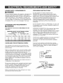
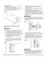
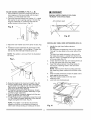
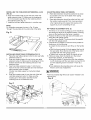
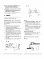
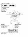
Operator's Manual
3.0 HP (Max. Developed)
10" Inch Blade
5000 R.P.M.
TABLE SAW
Model No.
137.248830
CAUTION:
•
•
•
•
•
Before using this Table Saw,
read this manual and follow
all its Safety Rules and
Operating Instructions
Safety Instructions
Installation
Operation
Maintenance
Parts List
Customer
Help Line
1-800-843-1682
Sears, Roebuck and Co., Hoffman Estates, IL 60179 USA
Visit our Craftsman website: www.sears.com/craftsman
Part No. 13724883001
SECTION
PAGE
Warranty ........................................
Product Specifications .......................
Power Tool Safety ............................
Table Saw Safety ..............................
Electrical Requirements and Safety ......
Accessories and Attachments ..............
Tools Needed For Assembly ................
Carton Contents ..............................
2
2
3
4
5
6
6
6
SECTION
PAGE
Know Your Table Saw .......................
Assembly and Adjustments .................
Operation .......................................
Maintenance ...................................
Troubleshooting Guide .......................
Parts List ........................................
Push Stick Pattern ...........................
8
9
16
20
21
22
30
FULL ONE YEAR WARRANTY
If this product fails due to a defect in material or workmanship within one year from the date of purchase, Sears will
at its option repair or replace it free of charge.
Contact a Sears Service Centre for replacement.
If this product is used for commercial or rental purposes, this warranty applies only for 90 days from the date of
purchase.
This warranty is in addition to any statutory warranty.
Sears, Roebuck & Co., Dept. 817 WA, Hoffman Estates, IL 60179
[A WARNING I
Some dust created by power sanding, sawing, grinding, drilling and other construction activities contains
chemicals known to the state of California to cause cancer, birth defects or other reproductive harm. Some
examples of these chemicals are:
• Lead from lead-based paints
• Crystalline silica from bricks, cement and other masonry products
• Arsenic and chromium from chemically treated lumber
Your risk from these exposures varies, depending on how often you do this type of work. To reduce your
exposure to these chemicals work in a well-ventilated area and work with approved safety equipmentsuch
as dust
masks that are spec a y des gned to f ter out m croscop c part c es.
MOTOR
HP (Maximum developed) .....
Type ..................................
Amps .................................
Voltage ..............................
Hz ......................................
RPM (no load) ....................
Overload Protection .............
[A WARNING I
3.0
Universal
15
120
60
5000
YES
SAW
Table Size ........................
Table Extensions ...............
Extension Rip Capacity .......
Blade Size ........................
Arbor Size ........................
Rip Fence ........................
Miter Gauge ......................
Maximum Cut Depth @ 90%
Maximum Cut Depth @ 45°..
Maximum Dado Cut Width...
Net Weight ......................
26-7/64" x 19-1/2"
3 - Left,Right,Rear
24" Right and Left
10" Diameter
5/8" Diameter
Self Aligning
T-Slotted
3"
2-1/2"
1/2"
65 LBS
To avoid electrical hazards, fire hazards or damage to the table saw, use proper circuit protection.
This table saw is wired at the factory for 110-120 Volt operation. It must be connected to a 110-120 Volt / 15 Ampere
time delay fuse or circuit breaker. To avoid shock or fire, replace power cord immediately if it is worn, cut or
damaged in any way.
Before using your table saw, it is critical that you read and understand these safety rules. Failure to follow these
rules could result in serious injury to you or damage to the table saw.
I_ WARNING]
Before using your table saw, it is critical that you read and understand these safety rules.
Failure to follow these rules could result in serious injury or damage to the table saw.
Good safety practices are a combination of common
sense, staying alert and understanding how to use your
power tool. To avoid mistakes that could cause serious
injury, do not plug in your power tool until you have read
and understood the following safety rules:
1.
READ and become familiar with this entire
Operator's Manual. LEARN the tool's applications,
limitations and possible hazards.
accessories. The use of improper accessories may
cause injury to you or damage to the tool.
15. REMOVE ADJUSTING KEYS AND WRENCHES.
Form the habit of checking to see that keys and
adjusting wrenches are removed from the tool
before turning ON.
16. NEVER LEAVE TOOL RUNNING UNATTENDED.
TURN THE POWER "OFF". Do not leave the tool
before it comes to a complete stop.
2. [A WARNING I
Look for this symbol that identifies important
safety precautions. It means CAUTION!
BECOME ALERT! YOUR SAFETY IS INVOLVED!
3.
NEVER OPERATE THIS MACHINE WITHOUT THE
SAFETY GUARD IN PLACE FOR ALL THROUGH
SAWING OPERATIONS.
4.
DO NOT USE IN A DANGEROUS ENVIRONMENT
such as damp or wet locations or exposure to rain.
Keep work area well lighted.
5.
DO NOT use power tools in the presence of
flammable liquids or gases.
6.
KEEP WORK AREA CLEAN. Cluttered areas and
benches invite accidents.
7.
KEEP CHILDREN AWAY. All visitors should be kept
at a safe distance from the work area.
8.
DO NOT FORCE THE TOOL. It will do the job better
and safer at the rate for which it was designed.
9.
USE THE RIGHT TOOL. Don't force the tool or
attachment to do a job for which it is not designed.
10. WEAR PROPER APPAREL. DO NOT wear loose
clothing, gloves, neckties, rings, bracelets or other
jewelry that may get caught in moving parts. Nonslip footwear is recommended. Wear protective hair
covering to contain long hair.
11. WEAR A FACE MASK OR DUST MASK. Sawing,
cutting and sanding operations produce dust.
12. DISCONNECT TOOLS before servicing and when
changing accessories such as blades, cutters, etc.
13. REDUCE THE RISK OF UNINTENTIONAL
STARTING. Make sure the switch is in the OFF
position before plugging into the power supply.
14. USE ONLY RECOMMENDED ACCESSORIES.
Consult the Operator's Manual for recommended
17. NEVER STAND ON THE TOOL. Serious injury
could occur if the tool is tipped or if the cutting tool is
unintentionally contacted.
18. DO NOT OVERREACH. Keep proper footing and
balance at all times.
19. MAINTAIN TOOLS WITH CARE. Keep tools sharp
and clean for most efficient and safest performance.
Follow instructions for lubricating and changing
accessories.
20. CHECK FOR DAMAGED OR LOOSE PARTS.
Before further use of the tool, a guard or other part
that is damaged should be carefully checked to
ensure it will operate properly and perform its
intended function. Check for alignment of moving
parts, binding of moving parts, loose mounting and
any other conditions that may affect its safe
operation. A guard or other part that is loose or
damaged should be properly adjusted repaired or
replaced.
21. MAKE WORKSHOP CHILD PROOF with padlocks,
master switches or by removing starter keys.
22. DO NOT operate the tool if you are under the
influence of any drugs, alcohol or medication that
could impair your ability to use the tool safely.
23. ALWAYS WEAR EYE PROTECTION. Any power
tool can throw foreign objects into your eyes that
could cause permanent eye damage. ALWAYS wear
safety goggles (not glasses) that comply with ANSI
safety standard Z87.1. Everyday glasses have only
impact resistant lenses. They ARE NOT safety
glasses.
NOTE: Glasses or goggles not in compliance with
ANSI Z87.1 could cause serious injury when they
break.
24. DIRECTION OF FEED. Feed work into a blade or
cutter against the direction of rotation of the blade or
cutter only.
.
2.
.
.
ALWAYS USE SAW BLADE GUARD, splitter and
anti-kickback pawls for every operation for which they
can be used, including through sawing. Through
sawing operations are those in which the blade cuts
completely through the workpiece when ripping or
crosscutting.
ALWAYS HOLD WORK FIRMLY against the miter
gauge or rip fence.
USE A PUSH STICK. Always use a push stick
especially when ripping narrow stock. Refer to ripping
instructions in this Operator's Manual where the push
stick is covered in detail. A pattern for making your
own push stick is included on page 30.
NEVER PERFORM ANY OPERATION FREE HAND,
which means using only your hands to support or
guide the workpiece. Always use either the fence
or the miter gauge to position and guide the work.
IA WARNINGI
WARNING: FREEHAND CUTTING IS THE MAJOR
CAUSE OF KICK-BACK & FINGER/HAND
AMPUTATIONS,
5.
NEVER STAND or have any part of your body in line
with the path of the saw blade. Keep your hands out
of the saw blade path.
6.
NEVER REACH behind or over the cutting tool for
any reason.
7.
REMOVE the rip fence when crosscutting.
8.
DO NOT USE a molding head with this saw.
9.
FEED WORK INTO THE BLADE against the
direction of rotation only.
10. NEVER use the rip fence as a cut-off gauge when
crosscutting.
11. NEVER ATTEMPT TO FREE A STALLED SAW
BLADE without first turning the saw OFF. Turn power
switch OFF immediately to prevent motor damage.
12. PROVIDE ADEQUATE SUPPORT to the rear and
the sides of the saw table for long or wide workpieces.
13. AVOID KICKBACKS (work thrown back towards you)
by keeping the blade sharp, the rip fence parallel to
the saw blade and by keeping the splitter, antikickback pawls and guards in place, aligned and
functioning. Do not release work before it has passed
all the way past the saw blade. Do not rip work that is
twisted, warped or does not have a straight edge to
guide it along the fence.
14. AVOID AWKWARD OPERATIONS and hand
positions where a sudden slip could cause your hand
to move into the saw blade.
15. NEVER USE SOLVENTS to clean plastic parts.
Solvents could possibly dissolve or otherwise
damage the material. Only a soft damp cloth should
be used to clean plastic parts.
16 MOUNT your table saw on a bench or stand before
performing any cutting operations. Refer to
ASSEMBLY AND ADJUSTMENTS on page 9.
17. NEVER CUT METALS or materials which may make
hazardous dust.
18. ALWAYS USE IN WELL-VENTILATED AREA.
Remove sawdust frequently. Clean out sawdust from
the interior of the saw to prevent a potential fire
hazard.
19. NEVER LEAVE THE SAW RUNNING
UNATTENDED. Do not leave the saw until it comes
to a complete stop.
20. Failure to provide sawdust fall-through and removal
hole (if mounting the saw onto a solid surface) will
allow sawdust to build up in the motor area resulting
in a fire hazard and potential motor damage (Please
refer to page 10 for details).
POWER
SUPPLY
REQUIREMENTS
I
A WARNING]
To avoidelectrical
hazards,fire
hazardsor damage tothe
tablesaw, use propercircuit
protection.
Always use a
separate electrical circuit for your tools. This power tool is
wired at the factory for 120V operation. Connect it to a
120V, 15 Amp circuit and use a 15 Amp time delay fuse
or circuit breaker. To avoid shock or fire, replace the cord
immediately if it is worn, cut or damaged in any way.
EXTENSION
CORD REQUIREMENTS
I
n WARNING]
Any extension cord must be GROUNDED for safe
operation.
MINIMUM GAUGE FOR EXTENSION CORDS
(AWG type / 120 Volt only)
Ampere Rating
Total length in feet
Not
More Than
More Than
25'
50'
100'
150'
0
6
18
16
16
14
6
10
18
16
14
12
10
12
16
16
14
12
GUIDELINES
FOR EXTENSION
CORDS
Any extension cord used for power tools MUST be
grounded (3-wire with two flat prongs and one round
ground prong).
Make sure the extension cord is in good condition. When
using an extension cord, make sure you use one heavy
enough to carry the current the tool will draw. An
undersized cord will cause a drop in line voltage resulting
in loss of power and overheating. The table above shows
the correct size to use according to extension cord length
and nameplate ampere rating. If in doubt, use the next
heavier gauge cord. The smaller the gauge number the
heavier the cord.
NOTE: The 12 to 16 Amp rating is correct for this tool. It
is highlighted in the table above.
Be sure your extension cord is properly wired and in good
condition. Always replace a damaged extension cord or
have it repaired by a qualified person before using it.
Protect your extension cords from sharp objects,
excessive heat and damp or wet areas.
Before connecting the saw to the extension cord, make
sure the saw switch is turned OFF.
GROUNDING
INSTRUCTIONS
IN THE EVENT OF A MALFUNCTION OR
BREAKDOWN, grounding provides a path of least
resistance for electric current and reduces the risk of
electric shock. This saw is equipped with an electric cord
that has an equipment grounding conductor and a
grounding plug. The plug MUST be plugged into a
matching receptacle that is properly installed and
grounded in accordance with ALL local codes and
ordinances.
DO NOT MODIFY THE PLUG PROVIDED. If it will not fit
the receptacle, have the proper receptacle installed by a
qualified electrician.
IMPROPER CONNECTION of the equipment grounding
conductor can result in risk of electric shock. The
conductor (wire) with the green insulation (with or without
yellow stripes) is the equipment grounding conductor. If
repair or replacement of the electric cord or plug is
necessary, DO NOT connect the equipment grounding
conductor to a live terminal.
CHECK with a qualified electrician or service personnel if
you do not completely understand the grounding
instructions, or if you are not sure the saw is properly
grounded.
Use only 3-wire extension cords that have 3-prong
grounding plugs and 3-pole grounding receptacles that
accept the saw's plug. Repair or replace damaged or
worn cords immediately.
3-Prong Plug
Grou_ng
Lug
_'/
_._--_._
_--
__
Make Sure This
It isC_nec_ed
toa
Known G rc_nd
%J-X
iF"
RECOMMENDED
ACCESSORIES
[,A WARNINGJ
Visit your Sears Hardware Department or see the Craftsman
Power and Hand Tools Catalog to purchase recommended
accessories for this power tool.
To avoid the risk of personal injury:
• Do not use adjustable (wobble) type dadoes or carbide
tipped dado blades; maximum dado width is 1/2".
• Do not use a dado with a diameter larger than 6".
• Do not use molding head set with this saw.
• Do not modify this power tool or use accessories not
recommended by Sears.
TOOLS NEEDED
screwdrive_
Adjustable
wrench
Combination
square
#2 Philtips screwdriver
Straight edge
AND CHECKING
CONTENTS
Separate all parts from packing materials. Check each part
with the illustration on the next page and the "Table of Loose
Parts" to make certain all items are accounted for, before
discarding any packing material.
[Ik WARNINGI
WARNINGJ
Medium
UNPACKING
If any part is missing or damaged, do not attempt to
assemble the table saw, plug in the power cord, or turn the
switch ON until the missing or damaged part is obtained and
is installed correctly.
TABLE OF LOOSE PARTS
ITEM
A.
B.
C.
D.
E.
F.
G.
H.
I.
J.
K.
L.
M.
N.
O.
X.
Y.
STAND
P.
Q.
R.
S.
T.
U.
V.
W.
DESCRIPTION
QUANTITY
Table saw assembly
1
Table extension
2
Rear table extension
1
Rear table extension tube
2
Location seat
5
Blade guard and splitter
1
Guard Mounting bolt, flat washer,
toothed washer, oval washer,
spring wasjer
1 each
Rip fence
1
Hand wheels
2
Dome nuts
2
Dado table insert
1
Miter gauge
1
Hex keys
1
Blade wrenches
2
Blade
1
Dust chute
1
Dust bag
1
Top short leg bracket
Top long leg bracket
Bottom short bracket
Bottom long bracket
Legs
Roller wheel assemblies &
mounting hardware
Stand mounting hardware
Fence storage hardware &
Parallel washers
2
2
2
2
4
1
1
1
NOTE: To make assembly easier, keep contents of box together.
Apply a coat of automobile
wax to the table. Wipe all parts
thoroughly with a clean dry cloth. This will reduce friction when
pushing the workiece.
UNPACKING
YOUR TABLE
SAW
B
A
K
D
7
L
G
M
J
_F
7
P
Q
R
S
T
V
W
Rip fence
Extension wing
locking lever
Blade guard
Table
insert
Side table
extension
Thermal overload
reset switch
ON/OFF
& safety
Bevel tilting
handwheel
Blade bevel
lock knob
switch
key
Bevel angle
pointer & scale
Blade elevation
handwheel
Table
Miter gauge
Table saw bBase
Rear outfeed table
extension
mounting
Roller wheel
locking
wing
lever
Stand
Leveling
foot
Stationary wheel
assembly
Dust collection
bag
holes
SAW MOUNTED TO WORK SURFACE (FIG. C)
1. If the leg set will not be used, the saw must be
properly secured to a sturdy workbench using the four
mounting holes at the base of the saw.
2. The surface of the table where the saw is to be
mounted must have a hole large enough to facilitate
sawdust fall-through and removal.
3. Square the saw on the mounting surface and mark
the location of the four 3/8" mounting holes (1).
4. Drill four 3/8" holes into the mounting surface.
5. Mark an 11" square (2) centered between the four
mounting holes (1).
6. Cut out and remove the square.
7. This opening will allow sawdust to fall through the
saw base.
8. Place the saw on the work surface, and align the
mounting holes of the saw with those drilled through
the surface.
9. Fasten the saw to the work surface.
BLADE RAISING HANDWHEEL (FIG. E, F)
1. Attach the handwheel (1) to the elevation screw (2)
at the front of the saw.
Make sure the slots (3) in the hub of the
handwheel engage with the pins (4). (Fig. E)
2. Attach and tighten the dome nut (5) at the end of the
shaft (Fig. F).
Fig. E
14WARNING
I
3
Do notoperatethismachine on thefloor.
Thisisvery
dangerousand may cause seriousinjury.
Fig,C
2
4
t
O
BLADE TILTING HANDWHEEL (FIG. G, F)
1. Attach the other handwheel (6) to the blade tilting
screw on the side of the saw in the same manner as
above.
2. Attach and tighten the handwheel dome nut (5).
Fig. F
O
14WARNING
I
Failure
to provide
sawdust
to build
fire or cause
the sawdust
up in the motor
motor
fall-through
hole will cause
area,
may result
which
damage,
Place the dust bag neck opening around the dust
chute and tie the dust bag with string.
in
RIP FENCE (Fig. G)
1. Lift upward on the rip fence handle (t) so that the
holding clamp (2) is fully extended.
2. Place the rip fence on the saw table. Lowering the
front of the fence onto the table first.
3. Push down on the fence handle (t) to lock.
Fig. G
1. Raise the blade arbor (4) (Fig. I) to the maximum
height by turning the blade raising handwheel
counterclockwise.
2. Remove the arbor nut (5) and flange (6), and then
remove the blade.
3. Install the saw blade onto the arbor with the blade
teeth pointing toward the front of the saw.
4. Install the flange (6) against the blade and thread the
arbor nut (5) as far as possible by hand making the
flat side of the nut is against the blade. Ensure that
the blade is flush against the inner side of the blade
flange.
Iz,
WARNING
l
To avoid possible injury and damage to the workpiece
be sure to install the blade with the teeth pointing toward
the front of table in the direction of the rotation arrow on
the blade guard.
Fig. I
4
5
INSTALLING AND CHANGING THE BLADE
(FIG. H, I, J)
I_ 'WARNING
]
To avoid injury from an accidental start, make sure
the switch is in the OFF position and the plug is
not connected to the power source outlet.
To avoid serious injury, table insert must be level
with the table. If the table insert is not level with the
table, adjust the screw (3) until it is level with the
table. To raise the insert, turn the screw
counterclockwise, to lower the insert, turn the
screw clockwise.
Remove the table insert (t) by unscrewing the two
screws (2, 3).Be careful not to lose the rubber
washer that is on the back screw (3) beneath the
table insert. (Fig. H)
5. To tighten the arbor nut (5) place the open-end
wrench jaws on the flats of the saw arbor to keep the
arbor from turning. (Fig. J)
6. Place the box-end wrench (8) on the arbor nut (5),
and turn clockwise (to the rear of the saw table).
7. Replace the blade insert in the table recess, insert
the screws through the front and rear holes and
tighten.
Fig. J
8
Fig. H
/
\
IA'IL
WARNING]
To avoid
2
injury
blade
contact,
insert
in place.
Use the dado
from
never
a thrown
operate
workpiece,
saw without
Use the saw blade
head
insert
when
insert
using
blade
parts, or
the proper
when
a dado.
sawing.
BLADE GUARD ASSEMBLY (FIG. K, L, M)
1. Set the blade to maximum height and the tilt to
zero degrees on the bevel scale with the hand
wheels. Lock the blade lock knob.
2. Place the external toothed lock washer (1) ,a steel
flat washer (2) and a spring washer (10) onto the
long hex head bolt (3). Insert the bolt into the
splitter bracket (4) as shown. (Fig. K)
[,l'kWARNING I
Improper splitter alignment can cause
"kickback" and serious injury,
Anti-kickback pawl
Fig. K
8
1
Fig. M
10 3
INSTALLING TABLE SIDE EXTENSIONS (FIG. N)
3. Place the oval washer (5) on the pivot rod (6). (Fig.
L)
4. Install the bracket assembly (4) at the rear of the
saw table and snugly - do not tighten. Thread the
bolt (3) into the internally threaded pivot rod.
1.
NOTE: The splitter is removed from the illustration
for clarity.
Fig. L
2.
3.
Identify the right hand table extension.
NOTES:
For illustration purposes the view in Fig. N looks
"through" the saw table to the under side of the
table.
The right hand table extension is the one with
the measuring scale (1) visible from the front of
the saw when it is installed to the right hand side
of the saw table (Fig. N).
Unlock both front and rear cam locking levers (2)
on the right hand side of the saw base.
Insert the table extension mounting tubes (3)
into the two matching holes in the cam lever
assemblies.
NOTE: Make sure the front mounting tube has
the measuring scale visible from the front of the
saw.
4.
6
5
5.
6.
Slide the table extension toward the table until it
rests against the saw table.
Place the location seat on the rear side
extension tube.
Lock both cam locking levers.
5. Raise the blade to the maximum height. (Fig. M)
6. Using a straight edge, check to see if the blade
guard splitter (8) is aligned with the saw blade (9).
Make sure the straight edge lies between the
teeth of the blade when aligning.
7. If straightening adjustment is necessary, loosen
the bolt (3) and shift the splitter assembly to right
or left for proper alignment.
8. When the splitter is properly aligned with the saw
blade, tighten the bolt, very tight.
9. If height adjustment is necessary, loosen the knob
(11 ) and raise the splitter assembly to the desired
height and tighten the knob. (Fig. K)
NOTE: The splitter must always be correctly
aligned so that the cut workpiece will pass on
either side without binding or twisting to the side,
Fig. N
INSTALLING THE TABLE SIDE EXTENSIONS- cont'd
ADJUSTING REAR TABLE EXTENSION
(FIG. O)
6. Snap one location seat (5) over the end of the rear
table extension tube (3). Make sure the locating pin
(6) in the location seat fits into the matching hole in
the extension tube (Fig. O).
7. Install the left hand table extension in a similar way.
1. Rear table extension should be positioned as close
2.
NOTE:
For illustration purposes the view in Fig. O looks
"through" the saw table to the under side of the table.
as possible to the rear of the table when ripping
short work pieces.
Rear table extension should be pulled out fully until
the location seat prevents it from moving outward
when ripping long work pieces that require extra
support as you are completing the cut.
RIP FENCE ADJUSTMENT
(FIG. Q)
1. The fence (1) is moved by lifting up on the handle (2)
and sliding the fence to the desired location. Pushing
down on the handle locks the fence in position.
2. Position the fence on the right side of the table, and
along the miter gauge groove.
3. Lock the fence handle. The fence should be parallel
with the miter gauge groove.
4. If adjustment is needed to make the fence parallel to
the groove, do the following:
• Loosen the two screws (3) and lift up on the handle
(2).
• Hold the fence bracket (4) firmly against the front of
the saw table. Move the far end of the fence until it
Fig. 0
is parallel with the miter gauge groove.
• Tighten both screws and push the handle to lock.
5. If fence is loose when the handle is in the locked
(downward) position, do the following:
• Move the handle (2) upward and turn the adjusting
nut (5) clockwise until the rear clamp is snug. Do not
turn the adjusting screw more than 1/4 turn at a
time.
• Over-tightening the adjusting screw will cause the
fence to come out of alignment.
INSTALLING REAR TABLE EXTENSION (FIG. P)
1. Place the rear table extension onto the two rear table
extension tubes (1).
2. Snap two location seats (4) over the two rear table
extension tubes (1).Make sure the locating pin in the
location seat fits into the matching hole (5) in the
extension tube.
3. Insert rear table extension tubes (1) into the two
holes in the rear of the saw table and into extension
tube brackets under the table.
Position rear table support so instruction labels
are up.
4. Snap one location seat (4) over the end of the left
rear table extension tube (1). Make sure the
locating pin in the location seat fits into the
matching hole in the extension tube.
IA WARNING
I
Failure to properly align fence can cause "kickback" and
serious injury.
Fig. Q
Fig. P
1
3
\
43
\
5
6
2
]3
RIP FENCE INDICATOR ADJUSTMENT (FIG. Q)
1. The rip fence indicator (6) points to the
measurement scale. The scale shows the
distance from the side of the fence to nearest side
of the blade.
2. Measure the actual distance with a rule. If there is
a difference between the measurement and the
indicator, adjust the indicator (6).
3. Loosen the screw (7) and slide the indicator to the
correct measurement on the scale. Tighten the
screw and remeasure with the rule.
Fig. Q-2
90 °
45°
3
IA WARNING
I
To avoid injury from an accidental start, make sure
the switch is in the OFF position and the plug is not
connected to the power source outlet.
ADJUSTING THE 90 ° AND 45" POSITIVE STOPS
(FIG.Q-I, Q-2, Q-3)
Your saw has positive stops that will quickly position
the saw blade at 90 ° to the table. Make adjustments
only if necessary.
90 ° Stop
1. Disconnect the saw from the power source.
2. Turn the blade elevation handwheel and raise
the blade to the maximum elevation.
3. Loosen the blade bevel lock handle (2) and
move the blade to the maximum vertical position.
Tighten the lock handle (2).
4. Place a combination square on the table and
against the blade (t)to determine if the blade is
90 ° to the table. (Fig. Q-2)
5. If the blade is not 90 ° to the table, loosen the two
set screws (4), located underneath the table saw,
(Fig. Q-3) with the hex key, and back off the
collar..
6. Loosen the bevel lock knob. Turn the blade
tilting handwheel to move the blade until it is 90 °
to the table.
7. Adjust the collar (5) so it contacts the bracket (3)
when the blade is 90 ° to the table. Tighten the
two set screws (4).
45 ° Stop
1. With the blade in the upright 90 ° position, loosen
the bevel lock knob and move the blade to the
45 ° position as far as it will go.
2. Place the combination square on the table as
shown in (Fig.Q-2) to check if the blade is 45 ° to
the table.
3. If the blade is not 45 ° to the table, loosen the two
set screws (4) (Fig. Q-3) with the hex key. Backoff the collar (5) then align the blade 45 ° to the
table, adjust the collar (5) so it contacts the
bracket (3).
4. Retighten the two set screws (4).
BLADE TILTING POINTER
1. When the blade is positioned at 90 °, adjust the
blade tilting pointer to read 0° on the scale.
2. Loosen the holding screw, position pointer over 0 °
and tighten the screw.
NOTE: Make a trial cut on scrap wood before
making critical cuts. Measure for exactness.
Fig. Q-3
Fig. Q-1
345
BLADE PARALLEL TO THE MITER GAUGE
GROOVE (FIG. R,S)
I_WARNING
I
This adjustment was made at the factory, but it
should be rechecked and adjusted if necessary.
IAWARNING
I
To preventpersonalinjury:
• Always disconnect
plugfromthepower source
when making any adjustments.
• Thisadjustmentmust be correct
orkickback
could result in a serious injury and accurate cuts
can not be made.
1. Remove the yellow switch key and unplug the saw.
2. Move the blade guard out of the way.
3. Raise the blade to the highest position and set at
the 0 ° angle (90 ° straight up).
4. Select and mark, with a felt tip marker, a blade
tooth having a "right set". Angle and positioning
this tooth 1/2" above the table at the front of the
Additional blade adjustments (Fig. S)
NOTE: The adjusting nuts are 8mm.
The adjusting mechanism is located above the blade
height adjusting hand wheel under the tabletop. If
the front and rear measurements are not the same,
adjust the alignment by the mechanism as follows:
If the blade is partial to right side:
1. Loosen the two nuts (1) and the right side screw,
then adjust the left side screw.
2. Tighten the nuts (1) and the right screw and
remeasure, as described in steps 4 to 9 in the
prior section.
If the blade is partial to left side:
3. Loosen the two nuts (t) and the left side screw,
then adjust the right screw to its position.
4. Tighten the nuts (t) and the left screw and
remeasure, as described in steps 4 to 9 in the
prior section.
5. Recheck blade clearance making sure that the
blade does not hit the table insert or other parts
when at the 90 ° and 45 ° settings.
saw.
5. Place the combination square base (1) into the
right side miter gauge groove (2). (Fig. R)
6. Adjust the rule so it touches the front marked tooth
and lock ruler so it holds its position in the square
assembly.
7. Rotate the blade bringing the marked tooth to the
rear and about 1/2 inch above the blade.
8. Carefully slide the combination square to the rear
until the ruler touches the marked tooth.
9. If the ruler touches the marked tooth at the front
and rear position, no adjustment is needed at this
time. If not, perform the adjustment procedure
described in next section.
Fig. R
Fig. S
f
BASIC
SAW OPERATIONS
RAISE THE BLADE (FIG. T)
To raise or lower the blade, turn the blade elevation
handwheel (1) to the desired blade height, and then
tighten lock handle (2) to maintain the desired blade
angle.
OVERLOAD PROTECTION (FIG. U)
This saw has an overload relay button (3) that resets
the motor after it shuts off due to overloading or low
voltage. If the motor stops during operation, turn the
ON / OFF switch to the OFF position. Wait about five
minutes for the motor to cool. Push in the reset
button (3) and turn the switch to the ON position.
I_, WARNING]
Fig. T
To avoid injury, the ON / OFF switch should be in the
OFF position and the plug removed from the power
source while the cool down takes place, to prevent
accidental starting when the reset button is pushed.
Overheating may be caused by misaligned parts or a
dull blade or undersized extensing cord. Inspect your
saw for proper setup before using it again.
1
2
TILTING THE BLADE (FIG. T)
1. To tilt the saw blade for bevel cutting, loosen the
lock knob (2) and turn the tilting handwheel (3).
2. Tighten the lock knob (2) to secure.
ON/OFF SWITCH (FIG. U)
The ON / OFF switch has a removable safety key.
With the key removed from the switch, unauthorized
and hazardous use by children and others is
minimized.
1. To turn the saw ON, insert key (1) into the slot in
the switch (2). Move the switch upward to the ON
position.
2. To turn the saw OFF, move the switch downward.
3. To lock the switch in the OFF position, grasp the
sides (or yellow part) of the switch toggle (1), and
pull it out.
4. With the switch key removed, the switch will not
operate.
5. If the switch key is removed while the saw is
running, it can be turned OFF but cannot be
restarted without re-inserting the switch key (t).
USING THE TABLE EXTENSION (FIG. V, V-l)
If the table extension is not parallel with the table.
Remove the bolts (1) and position the parallel
washers (2) between the table extension and tube
until it is parallel with the table, then tighten the bolts.
NOTE: Parallel washer (2) see page 6 for table of
loose parts ITEM: W-2
Fig. V
j_
1.
2.
3.
Release the extension lock handles.
Slide the extension out until the correct
measurement is displayed on the tube scale.
The user sights the scale off the edge of the
table.
Tighten all extension lock handles.
Fig. U
3
Fig. V-1
CUTTING OPERATIONS
There are two basic types of cuts: ripping and
crosscutting. Ripping is cutting along the length and
the grain of the workpiece. Crosscutting is cutting
either across the width or across the grain of the
workpiece. Neither ripping nor crosscutting may be
done safely freehand. Ripping requires the use of the
rip fence, and crosscutting requires the miter gauge.
LA
Fig. W
WARNINGJ
Before using the saw each and every time, check
the following:
1. Blade is tight on the arbor.
2. Bevel angle lock knob is tight.
3. If ripping, fence knob is tight and fence is
parallel to the miter gauge grooves.
4. Blade guard is in place and working properly.
5. Safety glasses are being worn.
The failure to adhere to these common safety rules,
and those printed in the front of this manual, can
greatly increase the likelihood of injury.
RIPPING (FIG. W, X)
WARNING
I
To prevent serious injury:
• Never use the miter gauge when ripping.
• Never use more than one rip fence during a single
cut.
• Do not allow familiarity or frequent use of your table
saw to cause careless mistakes. Remember that
even a careless fraction of a second is enough to
cause a severe injury.
• Keep both hands away from the blade and path of
the blade.
• The workpiece must have a straight edge against
the fence and must not be warped, twisted, or
bowed.
1. Remove the miter gauge. Secure the rip fence to the
table.
2. Raise the blade so it is about 1/8" higher than the
top of the workpiece.
3. Place the workpiece flat on the table and against the
fence. Keep the workpiece away from the blade.
4. Turn the saw ON and wait for the blade to come up
to speed.
5. Slowly feed the workpiece into the blade by pushing
forward only on the workpiece section (1) that will
pass between the blade and the fence. (Fig. W)
[,_ WARNING]
AVOID KICKBACK by pushingforwardon thesection
oftheworkpiecethatpasses between thebladeand
thefence.
]?
NOTE: Always use a push stick. When width or rip
narrower than 2" the push stick cannot be used
because the guard will interfere... Use the auxiliary
fence as shown are page 19.
6. Keep your thumbs off the table top. When both of
your thumbs touch the front edge of the table (2),
finish the cut with a push stick. Make a push stick
using the pattern on page 30.
7. The push stick (3) should always be used. (Fig. X)
8. Continue pushing the workpiece with the push stick
(3) until it passes the blade guard and clears the rear
of the table.
9. Never pull the piece back when the blade is turning.
Turn the switch OFF. When the blade completely
stops, then remove the workpiece.
Fig. X
BEVEL RIPPING
This cut is a combination of ripping while having the
blade bevel angle is set to an angle other than "0".
WARNING
I
Cutonlywiththeworkpieceand thefenceon theright
sideoftheblade.
RIPPING SMALL PIECES
I_WARNING
I
Avoid injury
fromthebladecontact.
Never make
through saw cuts narrower than 1/2" wide.
Fig. Y-1
1. It is unsafe to rip small pieces. Instead, rip a larger
piece to obtain the size of the desired piece.
2. When a small width is to be ripped and your hand
cannot be safely put between the blade and the
rip fence, use one or more push sticks to move the
workpiece.
CROSSCUTTING (FIG. Y)
WARNING
I
To preventseriousinjury:
• Do notallowfamiliarity
orfrequentuse ofyourtable
saw tocause carelessmistakes.
Remember that
even a careless
fraction
ofa second isenough to
cause a severe injury.
• Keep both hands away from the blade and the path
of the blade.
1. Remove the rip fence and place the miter gauge in
the left side groove.
2. Adjust the blade height so it is 1/8" higher than the
top of the workpiece.
3. Hold the workpiece firmly against the miter gauge
with the blade path in line with the desired cut
location. Keep the workpiece away from the blade.
4. Start the saw and wait for the blade (1) to come up to
full speed.
5. Keep the workpiece (2) against the face of the miter
gauge (3) and flat against the face of the gauge and
flat against the table. Then slowly push the workpiece
through the blade. (Fig. Y)
6. Do not try to pull the workpiece back with the blade
turning. Turn the switch OFF, and carefully slide the
workpiece out when the blade is completely stopped.
BEVEL CROSSCUTTING (FIG. Z)
This cutting operation is the same as crosscutting
except the blade is at bevel angle other than 0°.
1. Adjust the blade (1) to the desired angle, and
tighten the blade bevel lock knob.
2.Always work to the left side of the blade. The
miter gauge (3) must be in the left side groove (2).
It cannot be used in the right side groove unless
the miter angle is very sharp, as it will interfere
with the blade auard.
2
COMPOUND MITER CROSSCUTTING (FIG. AA)
This sawing operation is combining a miter angle
with a bevel angle.
1. Set the miter gauge (3) to the desired angle. Use
only the left side groove (2).
2. Set the blade (1) bevel to the desired angle then
lock in position.
3. Carefully push the miter gauge to begin the cutting
operation.
USING WOOD FACING ON THE MITER GAUGE
(Fig. Y-l)
Slots are provided in the miter gauge for attaching an
Fig. AA
auxiliary facing (1) to make it easier to cut very long or
short pieces. Select a suitable piece of smooth wood,
drill two holes through it and attach it the miter gauge
face with screws. Make sure the facing does not interfere
with the proper operation of the sawblade guard. When
cutting long workpieces, you can make a simple support by
clamping a piece of plywood to a sawhorse.
3
2
1
MITERING (FIG. BB)
This sawing operation is the same as crosscutting
except the miter gauge is locked at an angle other than
90 °
1_Hold the workpiece (2) firmly against the miter
gauge (3).
2. Feed the workpiece slowly into the blade (1) to
prevent the workpiece from moving.
Fig. BB
Fig. CC-1
30"
3/8' Thick plywood base
i
27"
2
Attach auxiliary fence to rip fence with two "C" clamps.
(Fig. CC-2)
Fig. CC-2
USING WOOD FACING ON THE RIP FENCE (FIG.
CC)
When performing some special cutting operations, add
a wood facing (1) to either side of the rip fence (2).
1. Use a smooth straight 3/4" thick wood board (1) that
is as long as the rip fence.
2. Attach the wood facing to the fence with wood screw
(3) through the hole in the fence. A wood fence
should be used when ripping material such as thin
paneling to prevent the material from catching
between the bottom of the fence and the table.
Fig. CC
AUXILIARY FENCE (FIG. CC-1)
Making the base:
• Start with a piece of 3/8" plywood at least 5-1/2"
wide or wider and 30" long or longer.
• Cut the piece to shape and size shown:
Making the side:
• Start with a piece of 3/4" plywood at least 2-3/8"
wide or wider and 27" long or longer/
• Cut the piece to shape and size shown:
Putting it together:
• Put the pieces together, as shown:
DADO CUTS (FIG. DD)
1. The dado table insert is included with this saw.
Remove saw blade, blade guard, then install the
dado, and dado table insert.
2. Instruction for operating the dado is packed with the
separately purchased dado set.
3. The arbor (1) on this saw restricts the maximum
width of the cut to 1/2".
4. It is not necessary to install the outside flange (2)
before screwing on the arbor nut (3). Make sure that
the arbor nut (3) is tight, and that at least one thread
of the arbor sticks out past the nut.
5. Use only the 6" dado set and keep the width t/2" or
less. It will be necessary to remove the blade guard
and splitter when using a dado blade. Always use
caution when operating a dado blade.
6. Use only the correct number of round outside blades
and inside chippers as shown in the dado set's
instruction manual. Blades/chippers must not
exceed 1/2".
7. Check saw to ensure that the dado will not strike the
housing, insert, or motor when in operation.
IIIL
WARNING
l
For your own safety, always replace the blade, blade
guard assembly, and blade insert when you are
finished with the dado operation.
Fig. DD
z_z
j2
J
[A'i WARNING I
Make sure the screw heads do not stick out from the
bottom of the base, they must be flush or recessed.
The bottom must be flat and smooth enough to rest on
the saw table without rocking.
]9
\
'_3
MAINTAINING
GENERAL
YOUR
TABLE
SAW
Fig. EE
MAINTENANCE
IA WARNING
I
For your own safety, turn the switch OFF and remove the
switch key. Remove the plug from the power source outlet
before maintaining or lubricating your saw.
1. Clean out all sawdust that has accumulated inside the
saw cabinet and the motor.
2. Polish the saw table with an automotive wax to keep it
clean and to make it easier to slide the workpiece.
3. Clean cutting blades with pitch and gum remover.
4. A worn, cut, or damaged power cord should be replaced
immediately.
WARNING
I
All electrical or mechanical repairs should be attempted
only by a trained repair technician. Contact the nearest
Sears Service Center for service. Use only identical
replacement parts. Any other parts may create a hazard.
5. Use liquid dish washing detergent and water to clean all
plastic parts.
NOTE: Certain cleaning chemicals can damage plastic
parts.
6. Avoid use of the following cleaning chemicals or
solvents, ammonia and household detergents
containing ammonia.
BLADE RAISING AND TILTING MECHANISM (FIG. EE)
After each five hours of operation, the blade raising
mechanism and tilting mechanism should be checked for
looseness, binding, or other abnormalities. With the saw
dis-connected from the power source, turn the saw upside
down and alternately pull upward and downward on the
motor unit. Observe any movement of the motor mounting
mechanism. Looseness or play in the blade raising screw
(1) should be adjusted as follows:
1. Using a 14mm wrench, loosen nut (2).
2. Adjust nut (3) until it is finger-tight against the bracket
(4), then back off the nut (3) 1/6 turn.
3. Tighten nut (2) with the wrench, while holding nut (3)
in place. Maximum allowable play of screw rod (1) is
0.16" (4 mm).
/
Place a small amount of dry lubricant on bevel gear (2).
Screw rod (1) must be kept clean and free of sawdust, gum,
pitch, and other contaminants for smooth operation.
If excessive looseness is observed in any parts of the blade
raising mechanism or tilting mechanism, take the complete
unit to a Sears Service Center.
LUBRICATION
All motor bearings are permanently lubricated at the factory
and require no additional lubrication.
On all mechanical parts of your table saw where a pivot or
threaded rod are present, lubricate using graphite or silicone.
These dry lubricants will not hold sawdust as would oil or
grease.
I_WARNING
I
To avoidinjury
froman accidental
start,
turntheswitchOFF and alwaysremove theplugfrom thepower sourcebefore
makingany adjustments.
• ConsultyourlocalSears ServiceCenterifforany reasonthemotorwill
notrun.
SYMPTOM
POSSIBLE CAUSES
CORRECTIVE ACTION
Saw will not start
1. Saw not plugged in
2. Fuse blown or circuit breaker tripped
3. Cord damaged
1. Plug in saw
2. Replace fuse or reset circuit breaker
3. Have cord replaced by a Sears
Service Center
1. Check blade with square and adjust
positive stop
2. Check blade with square and adjust
to zero
1. Check and adjust rip fence
2. Select another piece of wood
Does not make accurate
45 ° and 90 ° rip cuts
1. Positive stop not adjusted correctly
2. Tilt angle pointer not set accurately
Material pinched blade
when ripping
1. Rip fence not aligned with blade
2. Warped wood, edge against fence is
not straight
Material binds on splitter
1. Splitter not aligned correctly with blade
1. Check and align splitter with blade
Saw makes unsatisfactory
cuts
1. Dull blade
2. Blade mounted backwards
3. Gum or pitch on blade
1. Replace blade
2. Turn the blade around
3. Remove blade and clean with
turpentine and coarse steel wool
4. Change the blade
5. Clean table with turpentine and
steel wool
1. Align rip fence with miter gauge slot
2. Align splitter with blade
3. Install and use rip fence
4. Install and use splitter (with guard)
5. Replace blade
6. Push material completely through
the guard kickback pawls before
releasing work
7. Tighten knob
1. Brush or blow out loose dust and
dirt
Material kicked back from
blade
Blade does not raise or tilt
freely
. Incorrect blade for work being done
5. Gum or pitch on blade or table causing
erratic feed
1. Rip fence out of adjustment
2. Splitter not aligned with blade
3. Feeding stock without rip fence
4. Splitter not in place
5. Dull blade
6. The operator letting go of material
before it is past saw blade
7. Miter angle lock knob is not tight
,
Sawdust and dirt in raising and tilting
mechanisms
Blade does not come up
to speed
1. Extension cord too light or too long
2. Low house voltage
1. Replace with adequate size cord
2. Contact your electric company
Machine vibrates
excessively
1. Saw not mounted securely to
workbench
2. Bench on uneven floor
1. Tighten all mounting hardware
2.
3. Damaged saw blade
3.
1. Miter gauge out of adjustment
1. Adjust miter gauge
Does not make accurate
45 ° and 90 ° cross cuts
2]
Reposition on flat level surface
Fasten to floor if necessary
Replace blade
10" TABLE SAW PARTS LIST
MODEL NO. 137.248830
IA WARNING
I
When servicing use only CRAFTSMAN replacement parts. Use of any other parts may create a HAZARD or cause product
damage.
IA WARNING
I
Any attempt to repair or replace electrical parts on this Table Saw may create a HAZARD unless repair is done by a qualified
service technician. Repair service is available at your nearest Sears Service Center.
Always order by Model Number and I.D. number.
Schematic
A
I.D. No. Description
2178
EXTENSION WING (RIGHT)
Size
1
I.D. No. Description
0KCX
CRRE PAN HD PLAIN WASHER
TAPPING SCREW
0KSW STRAIN RELIEF
1
0KWZ
Qty
1
Size
M5"08-10
Qty
4
1
2179
EXTENSION WING (LEFT)
09JK
WRENCH HEX.
LEAD WIRE ASS'Y
1
0B31
TABLE
1
10GN
UPER TUBE
1
0B3H
INSERT
1
10GP
UPER TUBE
1
0B3K
INSERT
1
10GQ
RIP FENCE ASS'Y
0B3R
WRENCH
1
10H4
UPER TUBE
1
1
0B84
WASHER
D=cp18
1
10H5
UPER TUBE
1
0BC2
LOCATION SEAT
#06
5
20KA
SCALE
1
0BCW
UPERTUBE
2
20KC
SCALE
1
0BCX
EXTENSION WING
1
20KD
SCALE
0BD2
WARNING LABEL
1
20WQ
HEX. HD. BOLT
0BD3
WARNING LABEL
1
20Z7
BLADE GUARDASS'Y
1
0J3U
WRENCH HEX.
1
211Q
SCALE
1
SCALE
1
1
#06
1
0J5L
FLAT WASHER
_/_5" 10-0.3
10
211R
0J6V
FLAT WASHER
3/16"3/8-0.022
6
22KU
WARNING LABEL
0J76
FLAT WASHER
114"314-1116
1
0J95
SPRING WASHER
_;'_
6
1
0B8A
0T00
WARNING STICK LABEL
SLIDING BASEASS'Y
0JAA
WASHER
_;'_
8
1
0T03
SLIDING BASE ASS'Y
0JAF
EXTERNAL TOOTH LOCK WASHER
_;_5
1
0SZY
0K9U
HEX. HD. TAPPING SCREW
M5"16-25
8
0SZZ
SLIDING BASE ASS'Y
SLIDING BASE ASS'Y
0KAP
CR.RE. PAN HD. TAPPING SCREW
M5"0.8-10
1
26J7
TRADE-MARK
0KCH
CR.RE. PAN HEAD TAPPING & WASHER SCREW
M5"0.8-12
2
28FE
LABEL
CAUTION LABEL
M6"1.0-50
1
1
1
1
1
1
1
1
-'_'.
o
_>
W
trn
u)
26Ji7
\
\
\
\
0
m
Fz
0
4_
CO
CO
10" TABLE SAW PARTS LIST
Schematic
MODEL NO. 137.248830
B
I.D. NO.
Description
Size
08VH
CI ,AMP.¢ ORD
#06
Qty
.D. NO.
)K25
Description
HEX.SOCKET
0AW4
BODY SHEI.L
#AM
)K3G
CR.RE.
0BIW
HANDLE
)K7K
CR. RE
0B_:_
SABI)LE
)K8C
CR. RECOUNT
0B24
SPkLN(}
)K9T
HEX. HD. TAPPING
0B27
_)[NTER
)K9U
HEX. HD. TAPPING
0B2B
NEEDLE POINTER
)KA4
CR.RE.
0B_
SWITCH BOX
)KC8
CR. RE TRUSS
0B4_
RETAIN[N(}
CLP
)KCX
CR.REPAN
0B4S
WARNIN(;
i.ABEL
)KDR
CR. RE
0B4L
TRADE-MARK
)KDU
CR. RE
0B99
SPACER
)KF6
CR. RE
0BgC
PLUNGER
)KHZ
CAP HD SQ NECK
BOLT
BAi_ ASS'Y
i_I_ACt(ET
#06
_,ABEI,
HO[SSiNG
Size
M5"0.8-20
Qty
1
M5"0.8-12
1
MB'1.0-12
2
M4"18-10
4
SCREW
M5"16-16
6
SCREW
M5"16-25
4
M4"16-16
2
M4"16-16
2
M5"0.8-10
2
PAN HD. SCREW
M5"0.8-10
1
PAN HD. SCREW
M6"1.0-12
2
PAN HD. SCREW
M4"0.7-8
2
M6"1.0-12
2
HD.CAP
SCREWS
PAN HD. SCREW
ROUND
& WASHER
WASHER
HD SCREW
HD. TAPPING
PAN HD. TAPPING
SCREW
HD TAPPING
HD PLAIN
SCREW
WASHER
SCREW
TAPPING
SCREW
0BgK
AN(;LE k()D
)KJ4
CAP HD SQ NECK
BOLT
M6"1.0-35
1
0BgP
CLAMP
)K J5
CAP HD SQ NECK
BOLT
M6X1.0-80
1
0BgW
BRACKET
)KMR
HEX. NUT
M5"0.8
T=4
1
0BA4
SPA(:ER
)KMS
HEX. NUT
M6"1.0
T=5
1
0BA9
SPA(:ER
)KMV
HEX. NUT
M10"1.5
T=8
1
0BAB
SHIM
)KMW
HEX. NUT
M10"1.5
T=4
1
0BA(:
SET N[JT
)KMY
HEX. NUT
M8"1.25
, T=6.5
1
)KQJ
CROWN
M8"1.25
T=12.5
2
_ 45
NUT
0BAE
ARBOR COLLAI_
0BAT
NUT
)KRX
HEXAGON
0BAU
SUPP(_RTI_
)LSL
CIRCUIT
BREAKER
0BAX
STIFFENER
)LWG
ROCKER
SWITCH
0BAY
SCREW BAI_
)QEF
MOTOR
0BAZ
BEAI_[N(} SEAT
)T04
CLAMP ASS'Y
0BB l
SHAFT
)STE
HEIGHT
REGULATING
0BPA
i,()CK
RING ASS'Y
0/4F
FCAT WASHER
PLATE
L-30!)
_6
KN()B
PARRLE
)SWY
HAND WHEELASS'Y
10GZ
SPACER
FCAT WASHER
_ 10=_0-0 2
0/6T
FCAT WASHER
3/16_3/4-1/16
10H7
POWER
0/6U
FCAT WASHER
3/16'_1/2-3_4
24FW
LABEL
0/70
FCAT WASHER
1_'_3_-7/64
20PM
DUST
0/76
FCAT WASHER
1_'_3_1/16
20Q9
BAG-DUST
21BN
BRACKET
FCAT WASHER
5/3_ =_13/32-3/64
0_8D
FCAT WASHER
3/8'_3/4-5/64
TOOTH
LOCK WASHER
BLADE
27QV
PARTS
24FS
INSTRUCNON
SPI_(}
PIN
]
SPI_(_
PIN
9
0JED
C-RING
A-16
1
0JEY
E-RING
E-9
1
0JXL
HEX. SOC
SET
M10"1.5-12
1
0KOZ
HEX. HD
SCREW
AND WASHER
M8"1.25-16
4
0K16
HEX. HD
SCREW
AND WASHER
M8"1.25-16
1
BOLTASS'Y
1
2
#06
1
ASS'Y
GROUP
MITER
0/CA
1
COLLECTOR
23PP
0/C9
1
1
1
21HH
EXTERNAL
SCREW
_ 4
CABLE
9
0_AE
3
1
0/4H
0_80
M6"1.0
1
)STF
'.
FLAT WASHER
SWITCH
1
5
#_3. #06
@_XI6-_
NUTAND
GAUGE
#06
1
#06
1
ASS'Y
1
ASS'Y
1
10"x5/8"
BOX CARTON
MANUAL
36T
1
1
W
"4"
_'
F-
m
\
OIPA
0
OT04
m
rz
0
k_
4_
CO
CO
0
10" TABLE SAW
MODEL NO. 137.248830
Part list for STAND
I,D. No.
0A4T
Description
BASE
Size
#06
Qty
2
0EAA
BRACKET
4
0EAN
UPPER SUPPORT
1
0EAP
UPPER SUPPORT
1
0EAY
UPPER SUPPORT
2
0EBB
BOTTOM SUPPORT BRACKET
2
0EBG
BOTTOM SUPPORT BRACKET
2
0J4F
FLAT WASHER
ci_8X16-2.5
4
0JPP
HEX. HD. BOLT
MSX1.25-30
4
0K7K
CR. RE. ROUND WASHER HD. SCREW
M6X1.0-12
2
0Z1G
CAP HD. SQ.NECK BOLT
MSX1.25-12
16
0KRQ
SERRATED TOOTHED HEXAGON FLANGE NUT
M6X1.0 T=6
2
0KRR
SERRATED TOOTHED HEXAGON FLANGE NUT
M8X1.25 , T=7.5
2O
243R
LEFT FRONT WHEEL ASS'Y
1
243S
LEFT REAR WHEEL ASS'Y
1
243T
RIGHT FRONT WHEEL ASS'Y
1
243U
RIGHT REAR WHEEL ASS'Y
1
r-
m
-.j
0
m
I--
Z
0
10" TABLE SAW
MODEL NO. 137.248830
Part list for MOTOR
I.D. NO.
DESCRIPTION
1502
FIELD ASS'Y
SIZE
1
0HX9
NEEDLE BEARING
1
0JAL
EXT.TOOTH LOCK WASHER
_;,_4
4
0JX3
HEX. SOC. SET SCREW
M5X0.8-8
2
0K3A
CR.RE. PAN HD. SCREW & WASHER
M5X0.8-30
4
0K5V
CR.-RE. COUND.HD.SCREW
M4X0.7-8
4
0KCP
CR.RE. PAN HEAD TAPPING & WASHER SCREW
M5X12-60
2
0KTH
STRAIN RELIEF
1
0QE9
MOTOR NAMEPLATE
1
0QEA
BRACKET
1
0QEC
ARBOR SHAFT ASS'Y
1
0QED
SUPPORT PLATE
1
0QM2
BRUSH HOLDER ASS'Y
2
0QQT
BRUSH ASS'Y
2
0QR0
BRUSH COVER
2
0R1Q
MOTOR HOUSING
0R1S
BEARING BUSHING
1
0R1Y
ARMATURE ASS'Y
1
0R20
BAFFLE
#06
#06
QTY
1
1
;r
o
--I
O
W
rrrl
(t)
f_fJ
/
i
\
\
\
\
\
;r
0
113
r-
Z
O
€_
4:_
co
co
€_
c_
[
]
l
_
,
i
.....
j
PUSH STICK
Make from 1/2" or 3/4"
wood or thickness
less than width of
material to be cut.
CAUTION!
Use only good
strong wood
or plywood.
Use a jigsaw or
,.._J
cut out.
Cut off here to
_--- push 1/2" wood. -
---
1/2" Squares.
Optional
hanging hole.
_
Your Home
For repair-in your home-of all major brand appliances,
lawn and garden equipment, or heating and cooling systems,
no matter who made it, no matter who sold it!
For the replacement parts, accessories and
Operator's Manuals that you need to do-it-yourself.
For Sears professional installation of home appliances
and items like garage door openers and water heaters.
1-800-4-MY-HOME ® (1-800-469-4663)
Call anytime, day or night (U.S.A. and Canada)
www.sears.com
www.sears.ca
Our Home
For repair of carry-in items like vacuums, lawn equipment,
and electronics, call or go on-line for the location of your nearest
Sears Parts & Repair Center.
1-800-488-1222
Call anytime,
day or night (U.S.A. only)
www.sears.com
To purchase a protection agreement on a product serviced by Sears:
1-800-827-6655
(U.S.A.)
Para pedir servicio de reparaci6n
a domicilio, y para ordenar piezas:
1-888-SU-HOGAR
(1-888-784-6427)
TM
sM
1-800-361-6665
(Canada)
Au Canada pour service en fran(_ais:
1-800-LE-FOYER
Mc
(1-800-533-6937)
www.sears.ca
Ski
® Registered Trademark /
Trademark / ' Service Mark of Sears, Roebuck and Co.
® Marca Registrada / TM Marca de Fabrica / SM_ Marca de Servicio de Sears, Roebuck and Co.
MD
MC Marque de commerce
/
Marque depos6e
de Sears,
Roebuck and Co.
© Sears, Roebuck and Co.
2004/R1