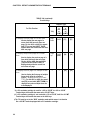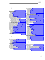
1
AT&T
DEFINITY
555-230-500
Issue 1, January 1992
® Communications System
Generic 1 & Generic 3
System Management
Copyright © 1991 AT&T
All Rights Reserved
Printed in U.S.A
Notice
While reasonable efforts were made to ensure that the
information in this document was complete and accurate
at the time of printing, AT&T can assume no responsibility
for any errors. Changes and corrections to the
information contained in this document may be
incorporated into future reissues.
Your Responsibility for Your System’s Security
You are responsible for the security of your system.
AT&T does not warrant that this product is immune from
or will prevent unauthorized use of common-carrier
telecornmunication services or facilities accessed through
or connected to it. AT&T will not be responsible for any
charges that result from such unauthorized use. Product
administration to prevent unauthorized use is your
responsibility and your system administrator should read
all documents provided with this product to fully
understand the features available that may reduce your
risk of incurring charges.
Federal Communications Commission (FCC)
Statement
This equipment generates, uses, and can radiate radiofrequency energy and, if not installed and used in
accordance with the instruction manual, may cause
interference to radio communications. It has been tested
and found to comply with the limits for a Class A
computing device pursuant to Subpart J of Part 15 of FCC
Rules, which are designed to provide reasonable
protection against such interference when operated in a
commercial environment.
Operation of this equipment in a residential area is Iikely
to cause interference, in which case the user at his/her
own expense will be required to take whatever measures
may be required to correct the interference.
Trademarks
DEFINITY is a registered trademark of AT&T. In this
document, DEFINITY Communications System Generic 3
is often abbreviated to DEFINITY Generic 3 or Generic 3.
DEFINITY Communications System Generic 1 is often
abbreviated to DEFINITY Generic 1 or Generic 1.
Acknowledgment
This document was prepared by the AT&T Technical
Publications Department Middletown NJ.
Contents
CHAPTER 1. INTRODUCTION .................................................................................................................
1-1
Overview ......................................................................................................................................
1-1
System Management ...........................................................................................................................
1-1
Initialization
1-2
.......................................................................................................................................................
Ongoing Administration .............................................................................................................................. 1-2
Record Keeping
........................................................................................................................................................... 1-2
When to Use This Manual ...........................................................................................................................................
1-3
Organization ..............................................................................................................................................................
1-3
Conventions Used in This Document .............................................................................................1-4
CHAPTER 2. DEFINITY ADMINISTRATION TERMINALS ......................................... ......... 2-1
Overview .............................................................................................................. ........ 2-1
715 MT Terminal .................................................................................................... ......... 2-3
513 BCT Keyboard ............................................................................................................
2-4
How to Program the Function Keys for a 513 BCT .................................................................. 2-11
4425, 4410, 610, and 615 MT Terminals .............................................................................................. 2-15
AT&T PC 6300 Keyboard ............................................................................................................. 2-15
CHAPTER 3. SYSTEM ADMINISTRATION ...............................................................3-1
Administration Sequence ....................................................................................................
3-1
CHAPTER 4. ADMINISTRATIVE TASKS—SYSTEM .......................................................4-1
How to Log In and Log Off ........................................................................................
4-1
How to Change Your Password ....................................................................................................... 4-3
How to Set Up the System to Allow Remote Administration ....................................................... 4-4
How to Administer the System From a Remote Location ............................................................ 4-6
4-6
How to Administer Netcon Channels .................................................................................................
i
How to Administer Dial Plan and Feature Access Codes ................................................................
4-8
How to Set Date and Time .......................................................................................................................
4-10
How to Print on Demand .........................................................................................................................
4-13
How to List History ...................................................................................................................
4-13
CHAPTER 5. ADMINISTRATIVE TASKS—VOICE TERMINAL ...................................... 5-1
How to Administer Voice Terminals ......................................................................................................
5-1
How to Administer Voice Terminals Without Hardware ...................................................................... 5-8
How to Administer Data Modules and Voice Terminal Adjuncts .................................................... 5-9
CHAPTER 6. HARDWARE RECONFIGURATION ................................................................ 6-1
Overview ..................................................................................................................................................
6-1
Circuit Pack Administration .....................................................................................................................
6-2
CHAPTER 7. SYSTEM BACKUP FOR DEFINITY G1 AND G3i ............................ 7-1
Save Translation ...............................................................................................................................................7-1
Save and Restore Recorded Announcements ................................................................................. 7-1
Tape Backup for a System Without the Duplication Option ......................................................
7-2
Tape Backup for a System With the Duplication Option ..............................................................
7-4
Tape Errors .......................................................................................................................
7-6
CHAPTER 8. SYSTEM BACKUP FOR DEFINITY G3r ........................................................8-1
Overview
....................................................................................................................................
8-1
Save Announcements Command ................................................................................................... 8-2
Restore Announcements Command ................................................................................................. 8-5
Error Conditions .......................................................................................................
8-7
Save Translation Command .........................................................................................................
8-9
Backup Command ................................................................................................................ 8-13
ii
Restore Command ..............................................................................................................................
8-15
Error Conditions .........................................................................................................................................
8-17
CHAPTER 9. REFERENCES ...................... ..................................................................... 9-1
CHAPTER 10. ABBREVIATIONS AND ACRONYMS ....................................................... 10-1
GLOSSARY .................................................................................................................. G-1
INDEX ..................................................................................................................................
I-1
iii
Figures
Figure 2-1.
715 MT Keyboard ..................................................................................
Figure 2-2.
513 BCT Keyboard Function Keys and Programmable Keys . . . . . . . . . . . . . . . . . . . . . . . . . . . 2-10
Figure 2-3.
Screen Labels Displayed When the LCL MENU Key is Pressed on a 513 BCT .... 2-12
Figure 2-4.
Screen Display When the USER PF SET-UP Key is Pressed on a 513 BCT ......... 2-13
Figure 2-5.
Assigning Administrative Functions to
Programmable Function Keys (F1, F2, and F3) on a 513 BCT .................................. 2-14
Figure 2-6.
4425 Keyboard Assignments .....................................................................................
2-16
Figure 2-7.
4410 Keyboard Assignments ...................................................................................
2-17
Figure 2-8.
610 MT Terminal Keyboard Assignments ....................................................................
2-18
Figure 2-9.
615 MT Keyboard Assignments Used Without a 513 Emulation Cartridge ............... 2-19
Figure 4-1.
Password Change Screen Form ..............................................................................................
Figure 4-2.
Date and Time Screen Form ......................................................................... 4-10
Figure 4-3.
Typical History Form .......................................................................................................
Figure 5-1.
Duplication Station Form Without a Data Module ......................................................... 5-6
Figure 5-2.
Duplication Station Form With a Data Module ..........................................................
5-6
Figure 7-1.
Save Translation—SPEA .......................................................................................
7-2
Figure 7-2.
Save Announcements Screen—SPEA ........................................................................... 7-3
Figure 7-3.
Save Translation—SPE_B .......................................................................................... 7-4
Figure 7-4.
Save Announcements—SPE_B ............................................................................... 7-5
Figure 8-1.
Save Translation Completion Status ............................................................................... 8-11
Figure 8-2.
Backup Completion Station ......................................................................................................
8-14
Figure 8-3.
Restore Completion Status ........................................................................................................
8-16
2-3
4-4
4-14
Tables
Table 2-A.
Terminal Keys ...................................................................................................... 2-5
Table 2-B.
Table 4-A.
Escape Sequences ....................................................................................................
Conversion to 24-Hour Clock ..............................................................................
Table 8-A.
Save Translation Command Error Codes ........................................................... 8-11
iv
2-15
4-12
CHAPTER 1. INTRODUCTION
CHAPTER 1. INTRODUCTION
Overview
This manual provides the information necessary for the System Manager to administer the
DEFINITY® Communications System Generic 1 and Generic 3 using any of the administration
terminals listed in Chapter 2. If system administration will be performed using the DEFINITY®
Communications System Generic 3 Management Applications (G3-MA), refer to DEFINITY®
Communications System Generic 3 Management Applications—Operations, 585-229-202, for
system management procedures. Unless otherwise noted, the DEFINITY Communications System will be referred to as the “system” throughout this document.
During the planning process, system requirements were identified by the Account Team and your
company. Those requirements were converted into orderable system hardware when the Account
Team configured the system. Those features were assigned on a system and per-terminal basis
using the forms in the appropriate DEFINITY® Communications System Implementation manual
for your DEFINITY System.
The forms in your Implementation manual provide an accurate representation of the screens that
are displayed on the system administration terminal. The forms are a blueprint showing how the
system and voice terminal features should be constructed.
In order to administer the system, the following must first be done:
●
●
Attend the System Customer Training Course.
Be familiar with the information in the DEFINITY® Communications System Generic 1
and Generic System 3—Description, 555-230-200, and the DEFINITY Communications
System Genetic 1 and Generic 3—Feature Description, 555-230-201.
●
Obtain a list from the Account Team and determine what hardware has been ordered.
●
Using your Implementation manual, complete:
– the Communications Survey
– the applicable system records and forms
●
Retain all the completed system forms in the Implementation manual for use in initializing
and administering the system.
System Management
System Management is the process by which the System Manager controls, maintains, and monitors the system. The System Manager provides reports which enable the manager to assess
system functionality and use. System Management also allows the System Manager to make
additions and/or changes as necessary to meet business requirements.
1-1
CHAPTER 1. lNTRODUCTION
System Manager's Role
The System Manager is responsible for the following:
●
Adding, changing, removing, and monitoring the system and voice terminal features on a
day-to-day basis
●
Performing system backup procedures
●
Monitoring system performance
●
Maintaining system security
-
Initialization
After the system is installed and initialized, the System Manager can administer the system using
the system administration terminal.
Once completed and duplicated, all forms from the Implementation manual should be sorted into
groups. For example, all voice terminal, hunt group, and trunk group forms should be in separate
groups. A copy of the Port Assignment Record should be available to keep track of the items
being installed in the system. These records can be used as a permanent record to show how
the system was initially set up. These records can be replaced as system and voice terminal
features are added or removed.
Ongoing Administration
Ongoing administration is the process of using system commands to perform a variety of functions to meet business requirements. These functions include: add, change, display, set time,
list, duplicate, perform system measurements, perform security and alarms, configure, monitor
system performance, and remove system and/or voice terminal features.
Record Keeping
Record keeping plays a vital role in system administration. Records provide a current status of
what hardware and which features have been installed.
The Port Assignment Record provides a record of how a system is initialized and administered.
Ports are the physical location on a circuit pack where terminals, trunks, or system adjuncts are
connected. Once port numbers are assigned, they become the “address” of the associated
equipment or facility in the system. It is necessary that a record be made and kept of port
assignments for system installation/initialization and ongoing administration.
A work request form or worksheet should be used to keep track of people who requested the
features and the features they desired.
Follow your company policy concerning keeping records. The applicable Implementation manual
provides the system-related screen forms.
1-2
CHAPTER 1. lNTRODUCTlON
When to Use This Manual
This manual, along with the Implementation manual, provides the necessary guidelines to administer the system. The Implementation manual, when completed, contains the filled-out forms that
reflect how your company wants to implement the system and voice terminal features. The information on these forms will be electronically entered in the system.
The Implementation manual provides all the details for gathering translation data. It also provides
detailed questions and procedures required to complete all the screen forms used to enter translation data into the system.
The System Description and Feature Description manuals should be used to answer any questions concerning system hardware and feature descriptions.
You should have thorough training on the following items before attempting to administer the
system:
●
System and voice terminal features
●
Hardware requirements
●
Port assignments
●
Manager I terminal operation
Organization
This document consists of the following chapters:
●
Chapter 1. Introduction describes this document.
●
Chapter 2. DEFINITY Administration Terminals describes the types of terminals which
can be used to administer DEFINITY Communications Systems and provides details on
keyboard layouts and keyboard mapping.
●
Chapter 3. System Administration provides the order in which features are to be
administered.
●
Chapter 4. Administrative Tasks-System gives details on performing a variety of
system administration tasks.
●
Chapter 5. Administrative Tasks-Voice Terminal gives details on performing a
variety of voice terminal administration tasks.
●
Chapter 6. Hardware Reconfiguration provides a list of commands to determine if the
correct circuit packs are installed so that new voice terminals, trunks, and data modules
can be added to the system.
●
Chapter 7. System Backup for DEFINITY G1 and G3i describes the tasks involved in
backing up the DEFINITY G1 and G3i systems, including saving translations, saving and
restoring recorded announcements, tape backup, and tape errors.
●
Chapter 8. System Backup for DEFINITY G3r describes the tasks involved in backing
up the DEFINITY G3r system, including saving translations, saving and restoring
recorded announcements, backup, restore, and tape errors.
1-3
CHAPTER 1. INTRODUCTION
●
●
Chapter 9. References provides a list of references for related documents.
Chapter 10. Abbreviations and Acronyms lists abbreviations and acronyms for terms
used in the DEFINlTY Communications System documentation.
●
Glossary defines terms used in the DEFINITY Communications System documentation.
●
Index
Conventions Used in This Document
This manual uses the following conventions:
●
The names of the comrnands are shown in the following typeface:
change system-parameters feature
1-4
●
Information you type is shown in the following typeface: EIA.
●
Information displayed on the screen is shown in the following typeface: login:
●
Keyboard keys are shown as follows: [RETURN]
●
Function keys are shown as follows: [CANCEL]
CHAPTER 2. DEFINITY ADMINISTRATION TERMINALS
CHAPTER 2. DEFINITY ADMINISTRATION TERMINALS
Overview
The terminal used to administer a DEFINITY Communications System is identified in this document as the system administration terminal or the terminal.
The terminal supplied with the system must be located within 50 feet of the system cabinet. The
terminal consists of a video display and a keyboard that allow a System Manager to communicate with the system. After initialization, the terminal is used to reconfigure translations and to
monitor system performance. The terminal can also be used by maintenance personnel.
The system can be equipped with any of the following terminals:
●
715 Multi-Task (MT) Terminal
●
513 BCT
●
610 BCT
●
615 MT Terminal
●
4410 Terminal
●
4425 Terminal
●
AT&T Personal Computer (PC) 6300 using an AT&T 513, 4410, or 4425 emulation
software package
If your DEFINITY System is being used with a G3-MA, refer to DEFINITY ® Communications
System Generic 3 Management Applications—Operations, 565-229-202, for terminal operating
instructions and system management procedures. No operating instructions are given in this
document.
The operating instructions in this document cover the 715, 513, 4410, and 4425 terminal types.
The operating instructions for the 610 BCT or 615 MT terminal are the same as for the 513 BCT if
the 610 or 615 MT terminal is supplied with the 513 emulation cartridge or as for the 4410 if the
513 emulation cartridge is not supplied with the 610 BCT or 615 MT terminal. The instructions
describe how the terminal keys can be used, for example, to enter, cancel, display, and change
system translations. Instructions on how to use the function keys are also provided.
The terminal key instructions are provided in Table 2-A.
2-1
CHAPTER 2. DEFINITY ADMINISTRATION TERMINALS
Refer to the following manuals for additional operation information on the 715, 513, 610, 4410, or
4425 terminals:
●
●
●
●
●
●
2-2
AT&T 715 MT Terminal User's Guide and Service Manual, 999-300-760, for the 715 terminal
AT&T Information Systems 513 Business Communications Terminal (BCT) Users Guide,
999-700-486IS, for the 513 BCT
AT&T Information Systems 610 Business Communications Terminal (BCT) Users Guide,
999-300-270IS, for the 610 BCT
AT&T Information Systems 615 Multi-Tasking Terminal Users Guide, 999-300-302IS, for
the 615 MT terminal
AT&T Information Systems Display Terminal Users Guide, 999-300-180IS, for the 4410
terminal
AT&T Information Systems Users Guide, 999-310-181IS, for the 4425 terminal
CHAPTER 2. DEFINITY ADMINISTRATION TERMINALS
715 MT Terminal
The 715 MT terminal emulates the AT&T 615 MT Terminal/System 75 Cartridge combination
(513 emulation) when operated in the “BCS” operating mode. The terminal operating mode is set
by selecting the Emulation option of the User Preferences submenu or via an escape
sequence.
Keyboard Overview
The 715 keyboard is equipped with special keys that allow the user to make corrections and do
editing functions. Various function keys perform specific functions. Figure 2-1 shows a layout of
the 715 keyboard.
See Table 2-A for a list of the cursor keys, function keys, and programmable keys and a brief
description.
The keyboard’s top row includes 14 function keys that provide access to the modules and
features of the terminal. They are used as terminal function keys, as screen-labeled keys, or as
function keys. For more information on using or programming the 715’s function keys, see the
AT&T 715 MT Terminal Users Guide and Service Manual, 999-300-760.
FIGURE 2-1. 715 MT Keyboard
2-3
CHAPTER 2. DEFINITY ADMINISTRATION TERMINALS
513 BCT Keyboard
The 513 BCT keyboard is equipped with special cursor keys that allow the user to make corrections and perform editing functions. Function keys that allow single keystrokes to do specific
functions are also provided. Each type of key used on the 513 BCT is described in the following
paragraphs.
See Table 2-A for a list of the cursor keys, function keys, and programmable keys and a brief
description.
Cursor Keys
The cursor keys allow the user to move the cursor between fields and pages on a screen form.
The cursor must be positioned on a field before the user can change information in that field.
The backspace key is used to correct typing mistakes by backspacing and overstriking mistyped
characters.
Programmable Keys
The 513 BCT keyboard is equipped with eight programmable keys ( [F1] to [F8] ) located at the
top of the keyboard. Each key can be programmed by the user to perform a specific function.
The keys are programmed by accessing the USER PF KEY SET-UP screen form. Figure 2-2
shows the layout of the 513 BCT keyboard.
Table 2-A contains a list of the cursor keys, function keys, and programmable keys and a brief
description.
Function Keys
Three function keys ([CANCL], [ENTER], and [RETURN]) are provided.
The [CANCL] key is used to erase a form or command. Once the key is pressed, the system
returns the user to the enter command: (tasks request) level and asks for a new command.
Any data entered on a screen form prior to pressing [CANCEL] is ignored. Any command entered is
ignored and the user is returned to the enter command: prompt.
The [ENTER] key is used to store the data entered on a screen form into the system’s memory.
The [RETURN] key, when pressed, automatically moves the cursor to the next field on a screen
form.
2-4
CHAPTER 2. DEFINITY ADMINISTRATION TERMINALS
TABLE 2-A. Terminal Keys
For This Function
715‡
Terminal Type
513
4410
or
or
610*
610†
or
or
615 MT* 615 MT†
Press Key Below:
4425
Cancel
CANCL
[F1]
[F1]
To clear and redraw a screen form
The system redraws the same screen.
For the 4410 or 4425, the associated
[F2] screen label (REFRESH) is
displayed when the add, change, or
display command is entered and the
screen form is displayed.
Clr/
Rfrsh
CLEAR
RFRSH
[F2]
[F2]
To clear all data in a field
The cursor must be positioned at the
field the user wants to clear before
pressing this key. For the 4410 or 4425,
the associated [F4] screen label
(CLEAR FIELD) is displayed when the
add or change command is entered and
the screen form is displayed.
(shift)
Clear
Home
CLEAR
RFRSH
(shift)
[F4]
[F4]
To cancel a screen form or command
Once the key is pressed, the system
returns the user to the enter command: (tasks request) level. Any data
entered on a screen form prior to pressing CANCL (Cancel) or [F1] is ignored.
For the 4410 or 4425, the associated
[F1] screen label (CANCEL) is automatically assigned.
* If a 513 emulation cartridge is used for a 610 or 615 MT, the 610 or 615 MT
Terminal keys will function the same as the 513 BCT keys.
† If a 513 emulation cartridge is not used with a 610 or 615 MT, the 610 or 615 MT
Terminal keys will function the same as the 4410 keys.
‡ The 715 must be set to the “BCS” emulation mode which causes it to function
like a 615 MT Terminal equipped with a 513 emulation cartridge.
2-5
CHAPTER 2. DEFINITY ADMINISTRATION TERMINALS
TABLE 2-A (continued).
Terminal Keys
For This Function
715‡
Terminal Type
513
4410
or
or
610*
610†
or
or
615 MT* 615 MT†
Press Key Below:
To display the next page of a screen form
Used to display the next page of a
screen form that has more than one
page. For the 4410 or 4425, the associated [F7] screen label (NEXT PAGE)
appears when the screen form has more
than one page.
Page
Down
PAGE
[F7]
[F7]
To display the previous page of a screen
form
Used to display the previous page of a
form which has more than one page.
For the 4410 or 4425, the associated
[F8] screen label (PREV PAGE) is
displayed only when the screen has
more than one page.
Page
up
PAGE
(shift)
[F8]
[F8]
—
—
[F6]
[F6]
To display the first page of a multiple screen
form
Used to display the first page of multiple
forms when using the command
(typical — display station xxxx count
1-10). For the 4410 or 4425, the associated [F6] screen label (NEXT FORM) is
displayed only when multiple forms are
to be displayed.
* If a 513 emulation cartridge is used for a 610 or 615 MT, the 610 or 615 MT
Terminal keys will function the same as the 513 BCT keys.
† If a 513 emulation cartridge is not used with a 610 or 615 MT, the610 or 615 MT
Terminal keys will function the same as the 4410 keys.
‡ The 715 must be set to the “BCS” emulation mode which causes it to function
like a 615 MT Terminal equipped with a 513 emulation cartridge.
2-6
4425
CHAPTER 2. DEFINITY ADMINISTRATION TERMINALS
TABLE 2-A (continued)
Terminal Keys
Terminal Type
513
4410
or
or
610†
610*
For This Function
4425
715‡
615 MT* 615 MT†
Press Key Below:
To display help information for a field or
command
Used to display help information on the
type of data that can be entered into the
field associated with the current cursor
position. The system delays all the
possible entries the user can input for
that field. This key can also be pressed
at the enter command: level to obtain
a list of all the system commands.
[HELP] can be pressed at other command levels to obtain a list of objects
and entries for identifiers. For the 4410
or 4425, the associated [F5] screen
label (HELP) is displayed when the user
logs into the system.
To move the cursor to the next field on a Iine
If the cursor is in the last field on a line,
then it moves to the first field on the
next line. If the cursor is in the last field
on the last line, then it moves to the first
field on the first line.
[Help]
or
[TAB]
or
[HELP]
[F5]
[F5]
or
or
or
[TAB]
[TAB]
[TAB]
[RETURN]
* If a 513 emulation cartridge is used for a 610 or 615 MT, the 610 or 615 MT
Terminal keys will function the same as the 513 BCT keys.
† If a 513 emulation cartridge is not used with a 610 or 615 MT, the 610 or 615 MT
Terminal keys will function the same as the 4410 keys.
‡ The 715 must be set to the “BCS” emulation mode which causes it to function
like a 615 MT Terminal equipped with a 513 emulation cartridge.
2-7
CHAPTER 2. DEFINITY ADMINISTRATION TERMINALS
TABLE 2-A (continued).
Terminal Keys
For This Function
715‡
To move the cursor to the previous field on a
line
If the cursor is in the first field on a line,
then it moves to the last field of the previous line. If it is in the first field of the
first line, then it moves to the last field of
the last line.
or
[TAB]
(shift)
Terminal Type
513
4410
or
610*
610†
or
or
615 MT* 615 MT†
Press Key Below:
or
or
[TAB]
[TAB]
(shift)
ROLL
[0]
To move the cursor to the previous line
If the cursor is on the first line, it moves
to the last line.
ROLL
[2]
[F3]
* If a 513 emulation cartridge is used for a 610 or 615 MT, the 610 or 615 MT
Terminal keys will function the same as the 513 BCT keys.
† lf a 513 emulation cartridge is not used with a 610 or 615 MT, the 610 or 615 MT
Terminal keys will function the same as the 4410 keys.
‡ The 715 must be set to the “BCS” emulation mode which causes it to function
like a 615 MT Terminal equipped with a 513 emulation cartridge.
2-8
or
[TAB]
(shift)
(shift)
To mOVe the cursor to the next Iine
If the cursor is on the last line, it moves
to the first line.
To store the data entered on a screen form
Used to enter into system memory the
data that is displayed on a screen form.
For the 4410 or 4425, the associated
[F3] screen label (ENTER) is displayed
when the add or change command is
entered and the associated screen form
is displayed.
4425
[F3]
CHAPTER 2. DEFINITY ADMINISTRATION TERMINALS
TABLE 2-A (continued).
Terminal Keys
For This Function
715‡
To update the BCMS screen form using
Monitor commands (G1)
Used to obtain immediate update of real
time status reports for agents and splits.
Used only with the BCMS monitor bcms
split and monitor bcms system commands.
[F6]
Terminal Type
513
4410
or
610*
610†
or
615 MT* 615 MT†
Press Key Below:
[F6]
[F6]
*
If a 513 emulation cartridge is used for a 610 or 615 MT, the 610 or 615 MT
Terminal keys will function the same as the 513 BCT keys.
†
If a 513 emulation cartridge is not used with a 610 or 615 MT, the 610 or 615 MT
Terminal keys will function the same as the 4410 keys.
‡
The 715 must be set to the “BCS” emulation mode which causes it to function
like a 615 MT Terminal equipped with a 513 emulation cartridge.
4425
[F6]
2-9
CHAPTER 2. DEFINITY ADMINISTRATION TERMINALS
NUMERIC LEGENDS ARE LOCATED ON
THE FRONT SURFACES OF THE
MATRIX AT THE BOTTOM OF
THE RIGHT CLUSTER.
FIGURE 2-2. 513 BCT Keyboard Function Keys and Programmable Keys
2-10
CHAPTER 2. DEFINITY ADMINISTRATION TERMINALS
How to Program the Function Keys for a 513 BCT
This section covers the procedures used to program the function keys for a 513 BCT. The programmable function keys can be used to save time by eliminating unnecessary typing. For example, a function key can be programmed to type the change station command. When the programmed key is pressed, change station appears on the terminal screen. The user then enters
the extension number associated with the voice terminal. The user should be familiar with the
User PF Keys section in the 513 BCT User's Guide, 999-700-486IS, before attempting to program the function keys. Program the function keys as follows:
1. Turn on the 513 BCT.
2. Log into the system.
3. Press [SHIFT] and [F5] (LCL MENU). See Figure 2-3.
4. The function for each programmable key is displayed at the bottom of the screen. See
Figure 2-3.
5. Press [F3] (USER PF SET UP). See Figure 2-4.
6. Screen displays the USER PF KEY SET-UP screen form. See Figure 2-4. The values
displayed are default values which can be changed.
7. Press [F8] (MONITOR MODE). This allows the user to program control characters associated with the USER PF KEY SET-UP screen form. See Figure 2-4 or 2-5.
8. To program [F1] , position the cursor under the Action heading for [F1] .
9. Type in send.
10. Position the cursor under the Label heading.
11. Enter the desired administration command. (This command can be typed on two lines.)
For example, if you type in duplicate station, this is the function assigned to [F1] .
See Figure 2-5 for examples on how to enter the duplicate station, display station and
change station commands.
12. Position the cursor under the Function String heading.
13. Type in the desired string, up to 80 characters.
14. Repeat the above steps for other keys you want to program.
15. Press the [F6] (SAVE ALL) key. This stores the currently displayed values for all the
keys that were programmed. The default values that were not changed remain with the
key.
16. The screen is blank except for the labels displayed at the bottom of the screen. See
Figure 2-3.
2-11
CHAPTER 2. DEFINITY ADMINISTRATION TERMINALS
F1
F2
F3
F4
F5
F6
F7
F8
FIGURE 2-3. Screen Labels Displayed When the LCL MENU Key is Pressed on a 513 BCT
2-12
CHAPTER 2. DEFINITY ADMINISTRATION TERMINALS
USER PF KEY SET-UP
Label
Action
Function String
f1:
keyed
f1
Oc
f2:
keyed
f2
Od
f3:
keyed
f3
Oe
f4:
keyed
f4
Of
f5:
keyed
f5
Og
f6:
keyed
f6
Oh
f7:
keyed
f 7
Oi
f8:
keyed
f8
Oj
F1
F2
F3
F4
F5
F6
F7
F8
FIGURE 2-4. Screen Display When the USER PF SET-UP Key is Pressed on a 513 BCT
2-13
CHAPTER 2. DEFINITY ADMINISTRATION TERMINALS
USER PF KEY SET-UP
Label
Action
Function String
DUPLICAT
STATION
duplicate station Hc
f1:
send
f2:
send
f3:
send
f4:
keyed
f4
Of
f5:
keyed
f5
Og
f6:
keyed
f6
Oh
f7:
keyed
f7
Oi
f8:
keyed
f8
Oj
F1
DISPLAY
STATION
CHANGE
STATION
F2
F3
display station Hc
change station Hc
F4
F5
F6
F7
F8
FIGURE 2-5. Assigning Administrative Functions to Programmable Function Keys
(F1, F2, and F3) on a 513 BCT
2-14
CHAPTER 2. DEFINITY ADMINISTRATION TERMINALS
4425, 4410, 610, and 615 MT Terminals
The 4425, 4410, 615 MT, and 610 terminals can also be used to administer DEFINITY Communication Systems. The 4425, 4410, 615 MT, and 610 terminals have eight function keys ([F1]
through [F8]) that are automatically assigned functions by the system software. These keys
allow the user to edit and fill out the screen forms and then submit the forms into system translations. Since the keys are assigned by the system, they cannot be programmed by the user.
The function assigned to each of the keys is displayed at the bottom of the 4425 or 4410 screen.
Figure 2-6 shows the location of the eight keys and their relationship to the screen for the 4425.
Figure 2-7 shows the same information for the 4410. Figure 2-8 shows the information for the
610. Figure 2-9 shows the information for the 615 MT Terminal.
When the user logs into the system and receives the enter command: prompt, the system
automatically assigns the CANCEL function to [F1] and the HELP function to [F5] .
When the user types in a command, the system automatically assigns the REFRESH function to
[F2] , the ENTER function to [F3] , and the CLEAR FIELD function to [F4] . These functions will
appear at the bottom of the screen after the station screen form is displayed.
If the screen form has more than one page, the system automatically assigns the NEXT PAGE
function to [F7] and the PREV PAGE function to [F8] . See Table 2-A for a description of how to
use the keys.
AT&T PC 6300 Keyboard
The PC 6300 function keys will work like a 4410 if the terminal is equipped with an AT&T 4410
emulation software package or a 4425 if it is equipped with an AT&T 4425 emulation software
package. The function keys are automatically assigned by system software when the user logs
in.
If the PC is equipped with an AT&T 513 emulation software package, the user must assign function keys such as HELP and NEXT PAGE to the function key labels on the PC screen and then
use these keys as function keys. The system does not automatically assign the function keys.
The escape sequences that must be assigned to the labels for the function keys are in the table
below:
TABLE 2-B. Escape Sequences
Label
HELP
NEXT PAGE
PREV PAGE
ENTER
CANCEL
REFRESH
Escape Sequence
[ESC] OM
[ESC] [U
[ESC] [V
[ESC] SB
[ESC] Ow
[ESC] Na
2-15
CHAPTER 2. DEFINITY ADMINISTRATION TERMINALS
FIGURE 2-6. 4425 Keyboard Assignments
2-16
CHAPTER 2. DEFINITY ADMINISTRATION TERMINALS
FIGURE 2-7. 4410 Keyboard Assignments
2-17
CHAPTER 2. DEFINITY ADMINISTRATION TERMINALS
FIGURE 2-8. 610 MT Terminal Keyboard Assignments
2-18
CHAPTER 2. DEFINITY ADMINISTRATION TERMINALS
FIGURE 2-9. 615 MT Keyboard Assignments Used Without a 513 Emulation Cartridge
2-19
CHAPTER 3. SYSTEM ADMINISTRATION
CHAPTER 3. SYSTEM ADMINISTRATION
Administration Sequence
After the system is installed, the System Manager must enter the translation data into the system
memory using the system administration terminal.
Before initializing the system, verify that the screen displays Login: If your terminal does not
display Login:, call your AT&T Account Team.
The Implementation manual for your DEFINlTY system provides the details for gathering the
translation data. It also provides detailed descriptions and procedures required to complete all
the screen forms used to enter translation data into the system. The document also provides the
administration commands that can be used to administer system and voice terminal features, and
error messages.
Obtain all duplicated forms from the Implementation manual and sort them into groups. For
example, forms for all voice terminals, and hunt and trunk groups should be separated. A copy
of the Port Assignment Record should be available to keep track of the items being installed in
the system.
When entering the translation data into the system, the System Manager should periodically save
the translations on tape. This creates a nonvolatile copy of the translation already entered into
the system. If a power outage or system failure occurs, the translation data saved on the tape
will not have to be entered again.
The system features should be entered into the switch in an ordered manner. The following is
the recommended order in which data should be entered into the system:
1. Login and Password (Change Password, if necessary)
2. Dial Plan
3. Feature Access Codes
4. System Features (Class of Service and Class of Restriction)
5. Console Parameters
6. Attendant Consoles
7. System Parameters
8. Voice Terminals
9. Modules
10. Netcon Channels
11. Groups (hunt groups, pickup groups, etc.)
12. Trunk Groups
13. Automatic Route Selection
14. Administered Connections
3-1
CHAPTER 3. SYSTEM ADMINISTRATION
These items cannot be added to the system; however, they can be changed to suit business
needs by entering the change command for that feature and changing the screen form. The add
command must be used to add trunks, pickup groups, hunt groups, and intercom groups. The
duplicate command can be used to duplicate voice terminals and data modules.
Login and Password
Once all the forms have been grouped, the System Manager can log into the system using the
terminal and receive the enter command: prompt. The System Manager can change the password, if so desired.
Establish a Dial Plan
The Dial Plan and Feature Access Codes (FACs) must be administered before voice terminals,
hunt groups, pickup groups, coverage groups, and attendant consoles can be administered. The
default values for the Dial Plan can be changed if they do not meet business requirements. The
Dial Plan can be changed by entering the command change dial plan and then changing the
default values on the screen form. The Dial Plan can use up to 5 digits.
Feature Access Codes
The defaulted values on the FAC form can be changed if they do not meet business requirements. FACs can be changed by entering the command change feature-access-codes and
then changing the default values on the screen form. The number of digits assigned to the FAC
must agree with the Dial Plan.
System Features
System features include the Class of Service (COS) and Class of Restriction (COR). These
features cannot be added; they can only be changed. To change these system features, enter
the command change cos for COS or change cor 0-63 for COR. Once the screen form is
displayed, the data entries can be changed.
Console Parameters and Attendant Consoles
Attendant consoles must be added one at a time. A vacant port on a digital line circuit pack is
required for each attendant console used. For reliability, attendant consoles should not be
assigned to the same circuit pack.
3-2
CHAPTER 3. SYSTEM ADMINISTRATION
System Parameters
System parameters allow the System Manager to assign values for system related features such
as Leave Word Calling (LWC), Hospitality Features, and Station Message Detail Recording
(SMDR).
Voice Terminals
Once the Dial Plan and FACs have been assigned, the System Manager can add the various
voice terminals. The duplicate command can be used to add the same types of voice terminals.
The extension number, location, type, and user name should be entered on the form.
Modules
Data modules can be assigned after voice terminal administration. Some data modules must be
added during voice terminal administration if the voice terminal has a data module. Other data
modules can be added separately.
Netcon Channels
Netcon Channels are used to provide switched data access for the following:
●
Station Message Detail Recording
●
On-premises administration/maintenance terminal
●
Remote administration/maintenance terminal
●
Property Management System (PMS) Link
●
Station Message Detail Recording
●
PMS Log Printer
●
Journal Printer
●
Recorded Announcements
●
System Printer
●
Remote Administration/Maintenance Terminal.
Netcon channels are assigned by entering the command add data-module (extension number
or next) and then entering Netcon in the Type field. Up to four Netcon channels can be
assigned. The channels can be added by entering the command duplicate data-module XXX
(extension number to be duplicated).
3-3
CHAPTER 3. SYSTEM ADMINISTRATION
Groups
After the voice terminals are added, the following items can be administered using the add com-
mands:
●
Abbreviated Dialing (System, Group, Enhanced)
●
Hunt Groups
●
Call Coverage Answer Groups
●
Pickup Groups
●
Intercom Groups
●
Terminating Extension Groups
Trunk Groups
Trunk groups are assigned by entering the command add trunk group 1-99 (or next). For the
Hospitality Reduction Parameter feature, only 50 trunk groups can be assigned.
The Network Access Features forms are filled out by the Account Team and must always be
entered. The Network Access forms are provided in two sections, Private and Public. The Public
Network Access includes the Trunk Group forms which, when entered, provide voice terminals
and attendants with access to and from the public network.
Private Network Access allows calls to be connected to several networks, such as the following:
3-4
●
Common Control Switching Arrangement (CCSA)
●
Digital Signal Level 1 (DS1) Interface
●
Electronic Tandem Network (ETN)
●
Enhanced Private Switched Communications Service (EPSCS) Access
●
Tandem Tie Trunk Network (TTN)
●
Integrated Services Digital Network-Primary Rate Interface (ISDN-PRI)
●
Software Defined Data Network (SDDN)
CHAPTER 4. ADMINISTRATIVE TASKS-SYSTEM
CHAPTER 4. ADMINISTRATIVE TASKS-SYSTEM
This chapter covers administrative tasks that allow the System Manager to change system
features to meet business requirements. The following administrative tasks are covered:
●
How to login and log off
●
How to change your password
●
How to set up the system to allow remote administration
●
How to administer the system from a remote location
●
How to administer Netcon channels
●
How to initially administer Dial Plan and Feature Access Codes (FACs)
●
How to set date and time
●
How to print on demand
●
How to list history
How to Log In and Log Off
The system translations are protected by the Iogin/password procedures. The login name identifies the type of terminal user to the system. The password is a personal code that can be
changed periodically to enhance system security. Before any system administration commands
or functions can be executed, the System Manager must successfully log in to the system and
receive the enter command: prompt.
WARNING: When logging into the system from a remote Iocation using the asynchronous link, the user should not be on the link too long nor leave the terminal unattended after logging in. This link is used by the system to
transmit alarms and errors to the Technical Service Center (TSC).
4-1
CHAPTER 4. ADMINISTRATIVE TASKS-SYSTEM
System Login Procedures
Note:
If your DEFINlTY system is being used with a G3-MA, refer to DEFINITY ® Communications System Generic 3 Management Applications—Operations, 585-229202, for login procedures.
The following procedure is used for logging into the system.
1. Turn on the terminal, if required. Screen displays:
.
Login:
2. Enter your login name and press [RETURN]. Screen displays:
Password:
3. Enter your password and press [RETURN].
For security reasons, the password is not displayed as you type it. The system verifies
that a valid login and password have been entered. If an invalid login or password is
entered, the system responds with
INCORRECT LOGIN
Login:
4. If INCORRECT LOGIN is displayed, you must repeat Steps 2 and 3.
5. If the system recognizes the Iogin and password name,
Terminal Type (Enter 513, 4410, or 4425): [513]
is displayed on the screen.
6. Do one of the following to identify the terminal type:
●
If the system is equipped with a 715 BCS, press [RETURN]. This will enter [513]
which is the defauLt terminal.
Note: The 715 must be set to the “BCS” emulation mode which causes it
to function like a 615 MT Terminal equipped with a 513 emulation
cartridge.
●
If the system is equipped with a 4410 terminal, enter 4410 and press [RETURN].
●
If the system is equipped with a 4425 terminal, enter 4425 and press [RETURN].
●
●
●
4-2
If the system is equipped with a 513 BCT, press [RETURN]. ([513] is the system
default.)
If the system is equipped with a 610 or 615 MT Terminal that has a 513 emulation cartridge, press [RETURN]. ([513] is the system default.)
If the system is equipped with a 610 or 615 MT Terminal that does not have the
513 emulation cartridge, enter 4410 and press [RETURN].
CHAPTER 4. ADMINISTRATIVE TASKS-SYSTEM
7. If enter command: is displayed, you can enter the desired command. Press [HELP] to
obtain the list of permissible commands.
System Logoff Procedure
The system logoff procedure should be performed any time the system terminal is not being
used. This assures the system translations will not be accidentally corrupted. To log off the system, type logoff and press [RETURN]. The system automatically disconnects you from the system.
If the user logs off at a terminal located within 50 feet from the switch, the system will automatically request a login. The terminal user accessing the maintenance board, data channel, or Netcon channel will be disconnected from the system when logoff is typed in. These users must
dial up the system in order to access the system.
How to Change Your Password
Password administration allows the user to change the password used to access the system.
This section provides the steps required to change a password.
The password should be changed if another person has discovered it. It should also be changed
if someone has gained access to the system and made changes to features that could alter business transactions.
The System Manager's password must be obtained from the installation organization responsible
for installing the system. The login name cannot be administered.
The System Manager's password should also be changed each time a new person takes over the
System Manager role. The password can be changed once the user has logged onto the system.
Do not give out passwords to anyone. Keep passwords in a locked place. Change passwords
periodically, at least every six months.
The following procedure is used to change a password.
1. Verify that the screen displays:
enter command:
2. Enter change password xxxxxxx (where xxxxxxx is the Iogin) and press
[RETURN].
3. The Verify Password Change form is dislayed on the screen (see Figure 4-1 ).
4. The cursor is positioned on Your Current Password field.
5. Enter the current password you logged in with and press [RETURN].
6. Cursor is positioned on New Password For Login Name.
7. Enter your new password and press [RETURN].
4-3
CHAPTER 4. ADMINISTRATIVE TASKS-SYSTEM
Note: Valid passwords contain four to seven alphabetic or numeric characters, or a
combination of alpha and numeric characters.
8. Cursor is positioned on
New
Password (enter again):
9. Re-enter your new password.
10. Press [ENTER].
11. Verify that the screen displays:
command completed successfully
enter command:
change
password
xxxxxxxx
Page 1 of 1
PASSWORD CHANGE
Change Password For Login Name: xxxxxxx
Your Current Password:
New Password For Login Name:
FIGURE 4-1. Password Change Screen Form
How to Set Up the System to Allow Remote Administration
Another way to administer the system, other than the system administration terminal, is from a
Remote Terminal. The Remote Terminal can be located either on or off the customer's premises.
All functions of the system administration terminal are retained by the Remote Terminal; however, terminal operation speed is limited to 1200 bps (bits per second) from a dial-up facility.
Up to five terminals can be connected to the system. In any type of configuration, only one terminal at a time can be used for administration purposes (such as adding, changing, or deleting system and voice terminal features). The other terminals may be used by Automatic Call Distribution
(ACD) supervisors to view Basic Call Management System (BCMS) information. To set up the
system to allow for Remote Administration, use the following steps:
Note: Remote Access numbers and barrier code assignments should be kept confidential
to prevent unauthorized persons from accessing the system. Toll and service
charges resulting from the unauthorized access of the system are the responsitility
of the customer. As a result, it is recommended that the Remote Access number and
associated Barrier Codes be changed periodically to maintain system security.
4-4
CHAPTER 4. ADMINISTRATIVE TASKS-SYSTEM
Note: Remote Access users should be careful when using any command that requires user
input such as next page. This command, if not used properly, will not let the system
time out after 30 minutes and logoff the user. If the command is not used properly,
system alarms cannot be reported which may affect system service.
1. If not translated previously, translate four Netcon channels. (See “How to Administer
Netcon Channels” in this chapter.)
2. Translate a Uniform Call Distribution (UCD) Hunt Group using a Hunt Group form.
a. In the Group Extension field, enter an extension number. If the system is
equipped with Direct Inward Dialing (DID), enter a DID extension number.
b. In the Group Members Assignment field, enter the four extension numbers
(non-DID numbers) previously assigned to the four Netcon channels.
If the system will be remotely administered from an on-premises terminal, no additional
translations are required.
If the system will be remotely administered from an off-premises location via a dial-up
facility, complete Steps 3 and 4.
3. Translate a pooled modem if not translated previously.
4. Translate a trunk group in one of the following ways described in the table below.
DID Equipped Systems
Using a DID Trunk Group form, translate
a new trunk. The NAME (TeI. number)
assigned in the Group Member
Assignments field must be the same
DID number assigned to the UCD hunt
group (see step 2a).
DID Equipped Systems
Using a Non-DID Trunk
Using a CO Trunk Group form, translate
a new trunk group. In both the Incoming Destination and Night SerVice fields, enter the UCD hunt group
extension number (see Step 2a).
Non-DID Equipped Systems
(calls made from Remote
[off-premises] terminal will be to the
Listed Directory Number [LDN])
If not translated previously, translate a
Trunk Group containing the LDN.
Non-DID Equipped Systems
(calls made from Remote
[off-premises] terminal will be to a
trunk dedicated to Remote Administration)
Using a CO Trunk Group form, translate
a new trunk group. In both the Incoming Destination and Night Service fields, enter the UCD group extension number (see Step 2a).
4-5
CHAPTER 4. ADMINISTRATIVE TASKS-SYSTEM
How to Administer the System From a Remote Location
Make sure data terminal speed settings are set at 1200 bps. Top speed for a data or Netcon
channel is 1200.
1. Using either the keyboard or a voice terminal, dial the UCD group extension number.
This number will be one of the following:
a. From off-premises:
●
a DID number (seven or 10 digits)
●
an LDN (seven or 10 digits)
●
a trunk number dedicated to Remote Administration (seven or 10 digits)
b. From on-premises:
●
an extension number
2. If a DID number, dedicated trunk number, or extension was dialed, receive data tone or
visually receive answer confirmation.
If an LDN was dialed, the attendant will answer. Ask to be transferred to the UCD group
extension number. Receive data tone or visually receive answer confirmation.
3. Screen displays login.
4. Enter your login and password.
5. Perform system administration.
6. Logoff and disconnect.
How to Administer Netcon Channels
This section contains the procedures required to administer system Netcon channels. The system has four Netcon channels (01 through 04) that are used to provide switched data access.
The system administration terminal, which is located within 50 feet of the system cabinet, is not
administered using Netcon channels. The system administration terminal should not be confused
with the on-premises or remote system administration terminals.
The Netcon channels are administered separately using the Data Module form and entering netcon in the Type field. The Netcon channels are assigned to the Network Control circuit pack.
One Netcon Channel form must be completed for each channel.
Once the Netcon channel has been assigned, the user must adminster the modules or modems
required to support SMDR, system administration/maintenance terminals, recorded announcements, and/or the PMS Iink.
The same commands used to administer data modules are also used to administer Netcon channels. The extension number entered at the end of the data module command determines which
Netcon channel will be added, displayed, duplicated, changed, removed, or printed.
4-6
CHAPTER 4. ADMINISTRATIVE TASKS-SYSTEM
All four Netcon channels must be assigned. The following steps can be used to add a data or
Netcon channel:
1. Verify that the terminal displays:
enter command:
2. Enter add data module 4444 where 4444 is the extension number assigned to the
Netcon channel. The extension number will appear in the Data Extension field on the
screen form. Press [RETURN]. The screen displays a Processor Data Module (PDM)
form. The cursor is positioned on the TYPE field.
3. In the TYPE field, enter netcon and press [RETURN].
4. Screen displays the Netcon Channel form.
5. The cursor is positioned on the Physical Channel field.
6. Enter a Netcon channel number from 01 through 04 and press [RETURN].
7. The cursor is positioned on the
Name
field.
8. Make no entry and press [RETURN].
9. Cursor is positioned on the COS field.
10. Enter a COS number from 0 through 15 and press [RETURN].
11. The cursor is positioned on the COR field.
12. Enter a COR number from 0 through 63 that will allow or deny access and press
[RETURN].
13. The cursor is positioned on the Abbreviated Dialing (AD) List 1 field.
14. Make no entry and press [ENTER].
15. The screen displays:
command successfully completed,
enter command:
16. Repeat Steps 1 through 16 until all four Netcon channels have been established. A different extension number must be entered for each Netcon channel. The system
automatically assigns the extension number if next is entered at the end of the add
data-module command (add data-module next).
The Netcon channels can be added by entering the command duplicate data-module xxxx
(extension number to be duplicated). This command must be entered for each Netcon channel being added.
If the system is administered for these features, after all four Netcon channels have been
assigned, the user can refer to “How to Administer System From a Remote Location” in this
chapter for more information.
4-7
CHAPTER 4. ADMINISTRATIVE TASKS-SYSTEM
How to Change a Netcon Channel
Netcon channels can be changed by entering the command change data module 4444 and
pressing [RETURN]. Extension number 4444 is the extension number assigned to the data or Netcon channel.
Once the form is displayed on the screen, the user can make changes. Once all changes have
been made, press [ENTER] to submit the changes into system translations.
How to List Netcon Channels
The list data-module command can be used to display a list of all Netcon channels that have
been assigned in the system. The display gives a list of all data modules and Netcon channels
and their associated data, which includes:
●
Extension
●
Port number
●
Type of module (Netcon channels are listed along with the other types of modules)
●
Name (if assigned)
●
Class of Service (COS)
●
Class of Restriction (COR)
●
Information Systems Network (ISN) (this field shows if the data module is connected to
the ISN)
The display data-module xxxx (extension number) [print] command can be used to obtain a
printout for one Netcon channel.
How to Administer Dial Plan and Feature Access Codes
The Dial Plan Record and the FACs can be administered together to insure continuity for the
number of digits assigned to FAC. The number of digits used to dial the FAC must agree with the
number of digits assigned to the FAC field on the Dial Plan Record. The system does not allow a
mismatch between these numbers. For example, if the Dial Plan Record has two digits assigned
for FAC, then each FAC must be assigned two digits. The user dials these digits to activate and
deactivate a feature.
The Dial Plan Record must be administered before assigning FACs, trunk access codes, and
voice terminal extensions. The Dial Plan Record can be administered as a stand-alone screen
form as long as the changes being made do not affect the FACs, Trunk Access Codes (TACs),
and voice terminal extension numbers. Once the TACs and voice terminal extension numbers
have been assigned, the user cannot change the Dial Plan Record.
Once the Dial Plan Record and FACs have been administered, the System Manager can change
the digits assigned to FACs as long as they agree with the Dial Plan Record. For example, the
System Manager can change a FAC from 12 to 13 as long as no other FAC is assigned to 13.
4-8
CHAPTER 4. ADMINISTRATIVE TASKS-SYSTEM
The following steps give an example of how to change a FAC from three to two digits.
1. Verify that the screen displays:
enter command:
2. Enter change feature-access-codes and press [RETURN].
3. The screen displays the FAC form.
4. Position the cursor over the 3-digit FAC and press the space bar until the 3-digit code
disappears.
5. Press [RETURN] and repeat the above step until all 3-digit FACs have been removed.
6. Press [ENTER]. The screen displays:
command successfully completed,
enter command:
7. Enter change dialplan and press [RETURN].
8. Screen displays the Dial Plan Record form.
9. Press [RETURN] until the cursor is positioned on the 1: Number of Digits field.
10. Enter 2 and press [ENTER]. The screen displays:
command successfully completed,
enter command:
11. Enter change feature-access-codes and press [RETURN].
12. The screen displays the FAC form.
13. Assign 2-digit FACs to the desired features. After all codes have been assigned, press
[ENTER]. The screen displays:
command successfully completed,
enter command:
4-9
CHAPTER 4. ADMINISTRATE TASKS-SYSTEM
How to Set Date and Time
The system date and time are set using the Date and Time form (see Figure 4-2). This form is
displayed on the terminal screen and is modified using the terminal keyboard. The time must be
reset for daylight savings time. The correct time and date assure that SMDR records are correct
for the records being kept. SMDR will not work until the date and time have been entered. Use
the following procedure to set the system date and time:
1. Log in.
2. Verify that the screen displays:
enter command:
3. Enter set time and press [RETURN].
4. Verify that the screen displays the Date and Time form (see Figure 4-2).
Note: The cursor is positioned on the
set time
of the Week: line.
Day
page 1 of 1
DATE AND TIME
DATE
Day of the Week:
Day of the Month: _
Month:
Year:
TIME
Hour: _
Minute: _
Second: XX
FIGURE 4-2. Date and Tlme Screen Form
5. Enter the day of the week (Sunday-Saturday) and press [RETURN].
Note: The cursor is positioned on Month:.
6. Enter the current month (January-December) and press [RETURN].
Note: The cursor is positioned on Day of the Month:.
7. Enter the day of the month (1-31) and press [RETURN].
Note: The cursor is positioned on Year:.
4-10
CHAPTER 4. ADMINISTRATIVE TASKS-SYSTEM
8. Enter the current year (1990-2099) and press [RETURN].
Note: The cursor is positioned on Hour:.
9. Enter the current hour (0-23) and press [RETURN]. Table 4-A shows the standard time
conversion to 24-hour time. Enter the 24-hour time as shown. For example, if the current
time is 2:00 p.m., enter 14.
Note: The cursor is positioned on Minute:.
10. Enter the current minute (0-59).
11. Press [ENTER].
12. Verify that the screen displays:
The set time form
enter command:
is
completed
successfully
Enter save translation and press [RETURN] so the correct time and date will be
entered in system translations. See Chapter 6 for save translation information.
13. Verify the date and time data by entering Display Time and pressing [RETURN].
Note: The Date and Time form is displayed showing all data entered, followed by:
enter command:
4-11
CHAPTER 4. ADMINISTRATIVE TASKS-SYSTEM
TABLE 4-A. Conversion to 24-Hour Clock
12-Hour
Standard Time
Clock
12:00 a.m.
1:00 a.m.
2:00 a.m.
3:00 a.m.
4:00 a.m.
5:00 a.m.
6:00 a.m.
7:00 a.m.
8:00 a.m.
9:00 a.m.
10:00 a.m.
11:00 a.m.
12:00 p.m.
1:00 p.m.
2:00 p.m.
3:00 p.m.
4:00 p.m.
5:00 p.m.
6:00 p.m.
7:00 p.m.
8:00 p.m.
9:00 p.m.
10:00 p.m.
11:00 p.m.
24-Hour
Clock
0
1
2
3
4
5
6
7
8
9
10
11
12
13
14
15
16
17
18
19
20
21
22
23
CHAPTER 4. ADMINISTRATIVE TASKS-SYSTEM
How to Print on Demand
The user can get a printout when print or the abbreviated version pr, is entered as the last qualifier for the list and display commands. For example, entering display abbreviated-dialing
group 20 print provides a printout for AD group number 20.
The terminal must have a printer connected to it before a hard copy printout can be obtained.
The following procedure can be used to obtain a printout of Pickup Group 25.
1. Log on.
2. Enter display pickup-group 25 print or display pickup-group 25 pr and
press [RETURN].
3. The screen displays the form for Pickup Group 25. At the same time, the screen form is
also printed out at the printer.
How to List History
This list history command provides a listing of the latest (250 maximum) completed “data affecting” administration and maintenance commands. The following commands are “data affecting”:
add
busyout
change
clear
disable
duplicate
enable
recycle
release
remove
reset
set
test
wp (write physical)
The history listing is stored by the system in a transaction log. This log is saved on tape as data
when the save translations command is performed. When the system cold starts or reboots, the
log is loaded from tape.
4-13
CHAPTER 4. ADMINISTRATIVE TASKS-SYSTEM
Figure 4-3 is an example of a typical list history command as displayed on the terminal. The
command results are displayed in last-in first-out order. The date that translations were last
saved on tape is printed followed by information under columns as follows:
●
Date: Day and month that the command was issued.
●
Time: Hour and minute that the command was issued.
●
Port: A 3- or 4-character identifier that shows which port or ports the user was connected
to. The identifiers and their associated meaning are:
Identifier
Port Connection
Extended Port Network (EPN)
NET
System Administration Terminal
TSC
SMDR
Maintenance circuit pack in expansion port network
Network Control circuit pack
Processor circuit pack
Processor circuit pack
Processor circuit pack
●
Login: The login of the user performing the data command.
●
Actn: The first four letters of the action command word.
●
Object: The first 12 letters of the object command word.
●
Qualifier: The first 36 letters of the qualifier (or qualifiers) command word.
list history
page 1
History
Date of Translation Loaded:
Date
---07/18
07/18
07/16
07/16
07/15
07/15
07/15
07/15
07/15
07/15
07/15
07/15
Time Port
---- ---12:34 EPN
12:23 EPN
09:44 SAT
09:22 SAT
15:25 SAT
15:18 SAT
15:09 SAT
15:06 SAT
15:04 SAT
15:02 SAT
15:01 SAT
15:00 SAT
Login
----cust2
cust2
craft
craft
cust
cust
cust
cust
cust
cust
cust
cust
19:53 Wed Jul 19, 1990
Actn Object
---- -----add
station
chan dialplan
rele station
busy station
chan station
add
station
add
station
add
station
add
station
add
station
add
station
add
station
Qualifier
--------1120
504
504
507
507
506
505
504
503
502
501
FIGURE 4-3. Typical History Form
4-14
CHAPTER 5. ADMINISTRATIVE TASKS-VOICE TERMINAL
CHAPTER 5. ADMINISTRATIVE TASKS—VOICE TERMINAL
How to Administer Voice Terminals
Voice terminal administration is an integrated set of procedures that allow the user to add,
change, remove, duplicate, display, and list the translation data associated with voice terminals.
The voice terminal must be installed, connected, and initialized in system translations before the
user can make a call. Other screen forms may be filled out to assign a voice terminal in a feature
operation, such as call pickup, call coverage, etc.
The following are the classes of operations in voice terminal administration:
Adding a voice terminal refers to entering the translation data needed to originate and/or
terminate calls at a terminal and to provide button access to features and functions.
●
●
Changing a voice terminal refers to updating the translation data associated with an
existing terminal.
●
●
●
●
Removing a voice terminal refers to deleting all the translation data of an existing terminal from the system.
Displaying a voice terminal refers to displaying the screen form for a voice terminal.
Duplicating a voice terminal refers to adding a voice terminal which has the same configuration as an existing voice terminal.
Listing allows the user to obtain a list of all, or a selected range of, voice terminals in the
system. The user can also obtain a list of all groups in which the voice terminal is a
member.
●
●
List extension type allows the user to identify a specific extension, or examine a range
of extensions. This command is also used to identify what types of groups the extension
belongs to and to list extension numbers and their types in a given range to help locate
and examine voice terminals.
Enhanced Terminal Administration allows for the administration of new voice terminals
that are not supported by the system software. For any new voice terminal type, the
Enhanced Terminal Administration feature allows new terminals to be “mapped” to an
existing or supported type. The mapping is accomplished by using the Alias Station
screen form. The alias name of the station can then be used when administering stations of that type.
Each voice terminal has its own screen form. The form contains fields for every data entry applicable to the terminal. Validity checks assure accurate data entry and consistency between fields.
Error messages are displayed whenever invalid data is detected. If an error message appears,
the HELP function provides a list of permissible entries for any field.
5-1
CHAPTER 5. ADMINISTRATIVE TASKS-VOICE TERMINAL
Before a voice terminal can be removed from the system, it must be removed from the following:
●
Code Calling List
●
Leave Word Calling (LWC) System Retrievers List
●
Hunt Groups Assigned to the Call Management System (CMS)
Translation data change may also be prevented when any affected feature is currently active; for
example, a voice terminal cannot be removed while the message waiting indicator is on. The
voice terminal must be idle before any features can be added or changed. Certain feature buttons must be unlocked (not in use) before they can be changed. The port number, message waiting indicator, and each button are locked. A voice terminal cannot be removed if one of the
locked items is active.
If voice terminal feature buttons are changed on the screen form, the labels for those feature buttons that appear on the voice terminal must also be changed to agree with the associated screen
form.
Note: Removing a voice terminal from a hunt group that has CMS will automatically
remove the voice terminal from the hunt group and CMS.
The information in the following paragraph must be used when adding, changing, or removing
voice terminals. A voice terminal cannot be assigned to a port number that is already assigned.
Note: If the circuit pack is not installed in the carrier, the System Manager can assign a circuit pack to the system by entering the command change circuit-pack and inputting
the circuit pack code beside the available slot number. Once the circuit pack code
has been assigned, the System Manager can then enter the appropriate port number
on the screen form for the voice terminal.
●
●
●
●
5-2
500, 2500, 2500 YMGK, 7101A, 7103A, 7102, 7102A, 7104A, 8102, or 8110 Voice Terminals: For all versions, up to right voice terminals can be assigned to one TN742
Analog Line circuit pack. Up to 16 voice terminals can be assigned to one TN746 or
TN746B Analog Line circuit pack. If you are using the 8102 or 8110 voice terminal with a
TN746 circuit pack, then auxiliary power is needed. Up to eight voice terminals can be
assigned to one TN769 Analog Line circuit pack. Up to 24 voice terminals can be connected to a DS1 Interface TN767 circuit pack
7403D, 7405D Voice Terminals, 510 BCT, or 513 BCT: Up to eight voice terminals can
be assigned to one TN754 Digital Line circuit pack. Up to 16 Digital Line circuit packs
may be placed on one port carrier if only 7403D voice terminals are used. Up to 12 Digital Line circuit packs may be placed on one port carrier if 7405D voice terminals are
used. In either case, the carrier may be fully loaded with other type circuit packs.
7434D, 7440, 741OD, or 7410 Plus: Up to eight voice terminals can be assigned to one
TN754 Digital Line circuit pack.
7401D, 7401D PIus, 7404D, 7406D, 7406BIS, 7406 Plus, 7407D, Enhanced 7407D
(02C), or 7407 Plus Voice Terminals: Up to eight voice terminals can be assigned to
one TN754 Digital Line circuit pack.
CHAPTER 5. ADMINISTRATIVE TASKS-VOICE TERMINAL
●
●
●
●
●
●
7303S, 7305S, or 7309H Voice Terminals: Up to eight voice terminals can be assigned
to one TN762 Hybrid Line circuit pack.
7302H01B, 7303H01B, 7305H01B, or 7305H02B Voice Terminals: Up to eight voice
terminals can be assigned to one TN762 Hybrid Line circuit pack.
ISDN 7505, 7508, or 7507 Voice Terminals: In a multipoint configuration, up to 24 voice
terminals can be assigned to the ISDN-BRI circuit pack TN556. In a point-to-point configuration, 12 voice terminals can be assigned.
ISDN 8503T Voice Terminal: In a multipoint configuration, up to 24 voice terminals can
be assigned to the ISDN-BRI circuit pack TN556. In a point-to-point configuration, 12
voice terminals can be assigned.
10, 20, or 30 MET Sets: Up to four voice terminals can be assigned to one TN735 Met
Line circuit pack.
CALLMASTER® Digital Voice Terminals: Up to eight CALLMASTER digital voice terminals can be connected to a TN754 or TN784 Digital Line circuit pack.
A voice terminal cannot have display buttons without having a display module.
Voice Terminal Commands
The following information explains how voice terminal commands are used to administer voice
terminals.
Add a Voice Terminal
Two processes are used to add a voice terminal: 1) physically installing the voice terminal and
2) adding voice terminal translations to memory. Adding translations to memory tells the system
the characteristics you want associated with the voice terminal and allows processing calls to and
from the voice terminal.
Note: Digital-type voice terminals should be assigned in the system before analog-type terminals.
●
To add a voice terminal to the system, enter add station 3222. In this example, add
is the action command, station is the object, and 3222 is the qualifier (value). By adding
a qualifier (3222), the system automatically assigns 3222 as an extension number in the
Extension # field on the form. Once the Voice Terminal form appears on the screen,
you can enter the desired data for that voice terminal.
When entering the command to add a voice terminal, the system checks to see if the extension
number is already assigned and if it is a valid extension number. If the extension number is
already assigned, the system responds with Extension Already Exists. If it is not a valid
extension number, the system responds with Invalid Extension. If one of the preceding happens, you must type in a valid extension number that is not assigned to any other voice terminal,
hunt group, terminating extension group, data module, or attendant call park extension. You can
also enter the command add station next which instructs the system to automatically assign the
next available extension number.
5-3
CHAPTER 5. ADMINISTRATIVE TASK-VOICE TERMINAL
The 7302H01B and the 7303H01B are assigned using the 7303S Voice Terminal form.
The 7305H01B and 7305H02B are assigned using the 7305S Voice Terminal form.
Change Information on a Voice Terminal
The change command allows you to change translations on an existing voice terminal.
●
To change information on a voice terminal, enter change station 3600. The system
displays the screen form that contains all the information currently assigned to extension
3600. Once the form appears on the screen, you can delete, add, or change any information for that extension, except you cannot change the extension number. To change
the extension number, you must remove the voice terminal and add it back along with the
new extension number, or you can duplicate the voice terminal with a new extension
number. Once duplicated, the old voice terminal can be removed from the system. The
new (duplicated) voice terminal must be assigned a new port number until the old voice
terminal is removed. Press [ENTER] after you make your changes to transmit the
changed information into the system memory.
When the change command is entered, the system checks to determine if the extension number
is assigned. If the number is assigned, the screen displays the appropriate screen form. If the
extension number is not valid, the system responds with Invalid Extension.
The module is automatioally removed when the voice terminal is changed.
Remove Voice Terminal
The remove command is used to delete a voice terminal from the system memory.
The system allows you to remove things in an orderly fashion, which assures that the system is
properly administered. Code calling items must be removed before the voice terminal can be
removed from translations.
The LWC super-retrievers list, secondary extension groups, and code calling items must be
removed before the voice terminal can be removed from translations.
A station user that is logged in as a CMS agent must be busied out before unplugging the station
to prevent faulty CMS reports.
The voice terminal must be busied out when the voice terminal is removed from the Automatic
Call Distribution (ACD) system.
Note: When a voice terminal that has a display is being removed from the system, the
display should be removed from the form for that voice terminal before the voice terminal is removed from the system.
The list groups-of-extension (extension) [print] command provides a list of groups the extension number belongs to.
●
5-4
To remove a voice terminal, enter remove station 3600. The system displays the Voice
Terminal form for extension 3600. Either press [ENTER] to remove the voice terminal
from the system, or press [CANCEL] to cancel the request. [CANCEL] should be pressed if
you entered the wrong extension number.
CHAPTER 5. ADMINISTRATIVE TASKS-VOICE TERMINAL
Display Information on a Voice Terminal
The display command allows you to look at a Voice Terminal form in the system. You cannot
change, add, or delete anything on the displayed form. If you see something that should be
changed, you must enter a change command such as change station 3600.
●
To look at the features assigned to extension 3600, enter display stat ion 3600. The
Voice Terminal form for extension 3600 is displayed on the screen. No changes or additions can be done using this command. To obtain a printout of the data displayed on the
terminal, enter print or pr at the end of the display command.
Indentify Groups to Which a Voice Terminal Belongs
The System Manager can use the list command to obtain a list of all groups to which a voice terminal belongs. The voice terminal must be removed from these groups before it can be removed
from the system.
The groups are searched and filed in the following order:
● Code Calling Lists
● Leave Word Calling System-Wide Retrievers List
● Secondary Extension Groups
● Data Extension Groups
The duplicate station command allows the user to add up to 16 voice terminals that have basically the same configuration as the voice terminal(s) being duplicated. Voice terminals are duplicated by entering the command duplicate station <extension> [start <extension>] [board
<address>] [count <1-16>] [1endpoint]. A brief description for each command variable is given
below.
●
●
●
●
extension—is the extension number of the voice terminal to be duplicated.
start extension—is an optional string that instructs the system to find unassigned extension numbers for the voice terminal(s) being added.
board address—i s an optional string that inducts the system to find unassigned ports in
the system for the voice terminal(s) being added.
count n—is the number of voice terminals to be added (1 to 16). This string also determines the number of lines that appear on the Duplication Station screen form. For example, if a 2 is entered, two lines appear on the form, if 10 is entered, 10 lines will appear
on the form.
Once the command is entered, the Duplication Station screen form shown in Figure 5-1 or 5-2 is
displayed on the administration terminal. Also displayed are the screen forms for the voice terminals being duplicated. Changes to the Voice Terminal screen form can be made, if desired.
The port number, extension number, and name will not be duplicated.
5-5
CHAPTER 5. ADMINISTRATIVE TASKS-VOICE TERMINAL
STATION
Ext
Port
Name
Security
Code
Room
Jack
Cable
FIGURE 5-1. Duplication Station Form Without a Data Module
STATION
Ext
Port
Name
Security
Code
Room
Jack
Cable
Data
Ext
FIGURE 5-2. Duplication Station Form With a Data Module
5-6
Data
Name
CHAPTER 5. ADMINISTRATIVE TASKS-VOICE TERMINAL
The following steps give a brief example of how to duplicate two 7403D voice terminals.
1. Enter duplication station 4000 [start extension 4001] [board] [count 2]
and press [RETURN]. The screen displays the Station Duplication form and the two duplicated Voice Terminal screen forms.
2. Enter information on the appropriate the Station Duplication screen form.
3. Change information on the Voice Terminal screen form if required.
4. Press [ENTER]. Forms are submitted and the system is placed in the list station mode. A
scan line for each voice terminal added is displayed on the screen prior to being submitted to system translations. After the voice terminals have been listed, the screen
displays:
command successfully complted,
enter command:
5-7
CHAPTER 5. ADMINISTRATIVE TASKS-VOICE TERMINAL
How to Administer Voice Terminals Without Hardware
Administration Without Hardware (AWOH) provides the ability to administer station forms without
specifying a port location. Stations administered as such will not cause alarm or errors to be
generated when the station is translated but not yet installed. These station types are referred to
as “phantom” stations. The AWOH feature supports the following applications:
●
●
●
●
Ability to administer station forms without specifying a port location
Ability to provide call coverage (induding AUDIX coverage), by use of phantom extensions, for users who do not have stations physically boated on the switch
Ability to use phantom extensions for Automatic Call Distribution (ACD) Dialed Number
Identification Service (DNIS). This application allows a phantom extension to be administered on the switch for each call type that needs to be identified to ACD agents. The
phantom extension is either use “Call Forwarded’ (via an attendant console) to an ACD
split, or its coverage path is defined to include the ACD split. The Name field that is
administered for the phantom extension will identify to the ACD agent which service the
caller is attempting to reach, allowing the agent to properly address the caller.
Ability to store station templates that can later be used with the duplicate station command when implementing many station forms of the same type in the system.
The primary use of the Administration Without Hardware feature is to streamline system initialization, major additions, and rearrangements/changes by allowing voice terminal translations to be
entered before the actual ports are assigned. Port assignments can be done at a later time, as
required.
The use of this feature is limited to analog, Digital Communications (DCP) (7400D series of terminals), and hybrid terminal types.
Administration Without Hardware is administered on a per voice terminal basis by the System
Manager. Normal station administration is required, with the exception of entering an X in the
Port field to indicate that there is no hardware associated with the station.
Note: This feature is not supported on ISDN-BRI stations or ISDN-BRI data modules.
Appropriate instructions are provided in each of the voice terminal administration instructions
located in the Implementation manual for your system.
5-8
CHAPTER 5. ADMINISTRATIVE TASK-VOICE TERMINAL
How to Administer Data Modules and Voice Terminal Adjuncts
Data Module Administration
The following types of data modules can be used by the system:
●
Recorded Announcement Data Module
●
Data Line Data Module (DLDM)
●
Digital Terminal Data Module (DTDM)
●
Modular Processor Data Module (MPDM)
●
Modular Trunk Data Module (MTDM)
●
7400A and 7400B Data Modules
●
7500B Data Module (BRI)
The screen forms used to assign modules are listed below:
●
●
●
●
Recorded Announcemont Data Module — has a built-in data module when used in conjunction with the Netcon data module which allows the system to transfer the recorded
announcements file from the TN750 Annoucement circuit pack to the system tape and
from the system tape back to the Announcement circuit pack. This module is assigned
using the Recorded Announcement Data Module screen form.
Data Line Data Module — is a data module used to connect EIA-232-C devices to the
system. The DLDM provides direct connection for up to eight ports. This module is
assigned using the DLDM screen form.
Modular Processor Data Module — is a multipurpose data module configured to provide
the digital switch interface to support various data interface requirements. One screen
form must be completed for each MPDM installed. Enter pdm in the Type field.
Modular Trunk Data Module — is a multipurpose data module configured to provide digital switch interface to support trunk data requirements. One screen form must be completed for each MTDM installed. Enter tdm in the Type field.
The DTDM screen form must be administered if “y” is entered in the Data Module field for voice
terminals that have a Data Module field. The extension number of a DTDM cannot be changed.
The DTDM must be removed and then added back with a new extension number.
The 7400A and 7400B Data Modules are desktop modules that offer full duplex asynchronous
communications for DCP voice terminals and asynchronous devices such as SMDR and PMS.
The 7400A and 7400B data modules can also be used on the trunk side which provides connectivity to asynchronous host computers. These modules are assigned using the Data Module form
assigned to the voice terminal that can have this type of module.
5-9
CHAPTER 5. ADMINISTRATIVE TASKS-VOICE TERMINAL
For the 7500B Data Module, multipoint administration is allowed for terminals with Service Profile
Identification (SPID) initialization capabilities. if the duplicate data-module command is used to
add a 7500B and the user wishes to add an SPID value which is different from the extension, the
SPID field must be modified after the Data Extension field is entered or modified.
The following commands can be used:
●
add data-module xxxx (ext. number or “next”)
If next is entered instead of an extension number, the system will automatically select
the next lowest available extension number. This command should not be used when
prefixed extensions have been assigned on the Dial Plan.
●
change data-module xxxx (ext. number)
●
display data-module xxxx (ext. number) [print]
●
duplicate data-module xxxx (extension number of data-module to be duplicated)
●
list data-module (starting ext. number) xxxx (count)
●
remove data-module or station xxxx (ext. number)
●
status data-module xxxx (extension number)
Hardware Requirements
A Digital Line circuit pack must be installed to avoid alarms before a PDM and Trunk Data
Module (TDM) can be administered. A TN726 Data Line circuit pack is needed for data line-type
data modules. A TN750 circuit pack is needed for the Recorded Annoucement data module.
5-10
CHAPTER 6. HARDWARE RECONFIGURATION
CHAPTER 6. HARDWARE RECONFIGURATION
Overview
Before voice terminals, trunks, and data modules can be added to the system, specific types of
circuit pack must already be installed in the cabinet. The System Manager must determine if the
required circuit pack exists in the system, and if a port on the circuit pack is vacant. If a vacant
port is not available, a circuit pack must be installed before the corresponding voice terminal or
trunk can be added.
The System Manager can use the Circuit Pack screen form to assign the circuit packs before
voice terminals, trunks, and data modules can be added to the system.
The system provides a set of commands that is used to display system and circuit pack (board)
configuration. These commands allow the System Manager to list the current system hardware
configuration. From this listing, the System Manager can determine if additional hardware (circuit
packs) is required.
When adding a new circuit pack, the carrier loading procedures in the Implementation manual
must be followed. All items must be entered for the Port Assignment Record.
The following commands are used to list system and circuit pack (board) configurations:
●
list configuration all
●
list configuration board (3-character board number)
●
list configuration station
●
list configuration trunk
●
list configuration control
●
list configuration software-vintage [long]
●
list configuration port-network (1-3)
●
list configuration carrier 2 character cabinet [1-3], carrier [A-E]
Whenever features are assigned to buttons on voice terminals, the associated button must be
labeled.
6-1
CHAPTER 6. HARDWARE RECONFIGURATION
Circuit Pack Administration
Circuit pack administration is a capability that allows theSystem Manager to assign circuit packs
to carrier slots before the circuit packs are actually installed in the slots. The circuit packs are
assigned on the Circuit Pack screen form. The form has five pages, one for each of the port carriers. Page 1 is for Carrier A, page 2 is for Carrier B, etc.
Before any voice terminals, attendant consoles, trunks, pooled modems, etc., can be assigned to
the system, the correct type of circuit pack must be installed in the appropriate slot or a circuit
pack must be assigned to the slot using the circuit pack administration form. The circuit packs
are assigned to slots using the circuit pack (TN circuit pack number) code.
Once the circuit packs have been assigned to a slot in the carrier, the System Manager can add
the appropriate voice terminals, trunks, etc., to the system.
The System Manager can assign a circuit pack to the system by entering the command change
circuit-pack and inputting the circuit pack code beside the available slot number. Once the circuit
pack code has been assigned, the System Manager can then enter the appropriate port number
on the screen form for the voice terminal, trunks, pooled modem, etc.
If administering without hardware (see “How to Administer Voice Terminals Without Hardware” in
Chapter 5 of this document), enter an X in the Port file on analog, digital, and hybrid voice terminals to indicate that there is no hardware associated with the port assignment. This permits
pre-administration of voice terminals that will be implemented at a later time. These voice terminals are referred to as “phantom stations.” Port assignments can be made at a later time.
The following commands can be used to administer circuit packs. Pressing [HELP] provides a list
of circuit pack codes that can be entered on the form.
6-2
●
display circuit-packs [print]
●
change circuit-pack
CHAPTER 7. SYSTEM BACKUP FOR DEFINITY G1 AND G3i
CHAPTER 7. SYSTEM BACKUP FOR DEFINITY G1 AND G3i
DEFINlTY G1 and G3i systems use a tape-only backup system with or without a duplication
option. In case of a power failure of ten minutes or more, the system translations can be
restored using the data on the system or backup tape.
Save Translation
To ensure that the tape drive cassette tape contains the most recent copy of the translation data,
the system can automatically save the translation data onto the cassette tape every 24 hours.
Note: Automatic daily backup of the system translation data is controlled by an entry in the
system parameters that is defaulted to “y” (yes), which means the system will
automatically save the translation data every 24 hours.
If many translation data changes are made, it is recommended that the System Manager save
the translation data using the save translation command. This will save the new changes on the
cassette tape without having to wait for the next automatic daily translation backup. If extensive
changes, additions, or deletions are made, translations should be saved more frequently, alternating the two tapes. Then, in case of a power outage, only the data entered since the last
“save” will be lost. See the “Tape Backup” sections of this chapter.
WARNING: It is recommended that “save translations” should be performed after
business hours so dial tone delays will not be encountered.
WARNING: “save translations” should not be performed if any tape alarm conditions
occur or if this system is having problems.
Save and Restore Recorded Announcements
The recorded announcements in the system can be saved on the system cassette tape by entering the command save announcements spe-active/spe-standby. These commands should
only be used after business hours or when the system is operating during a low usage period.
The system takes about 45 minutes to one hour to transfer the recorded announcements from
the announcement board to the system tape. During this time period, the administration terminal
cannot be used to administer the system until the transfer is complete; however, all other
administration terminals, if provided, are allowed to perform administration procedures.
The recorded announcements in the system can be restored back into the system memory from
the system tape by entering the command restore announcement. The system performs an
audit to make sure that the announcements on the announcement board match the announcements administered in the switch. If the restore announcements fails in a duplicated system
because of a tape or tape drive failure, the system will alarm the tape drive that didn’t restore and
switch to the standby Switch Processing Element (SPE) provided the standby is operational. The
restore announcements must then be re-entered on the new active SPE to restore the announcements.
7-1
CHAPTER 7. SYSTEM BACKUP FOR DEFINITY G1 AND G3i
Tape Backup for a System Without the Duplication Option
Two cassette tapes are provided with the system. It is recommended that backup copies of
the translation data be made weekly, or after many changes have been made to the translation
data. This will minimize the loss of recent translation data changes if the cassette tapes in the
system become damaged.
The following procedure can be used to make a backup tape:
1. Remove the cassette tape from the tape drive.
2. Insert the backup cassette tape into the tape drive.
3. Login to the terminal.
4. Verify that the screen displays:
enter command:
5. Enter save translation and press [RETURN]. This command instructs the system to
take all translation information in memory and write it onto the cassette tape.
6. The screen displays:
SPE A
save translation
SAVE TRANSLATION
Processor
Command Completion Status
Success
SPE_A
Error Code
0
Command successfully completely
enter command:
FIGURE 7-1. Save Translation—SPEA
7. Verify that a 0 is displayed in the Error Code column. A 0 indicates that the save
translation was successfully completed for the tape drive. If a 0 did not appear, the
save translation did not complete. Record the “error code number” and the “error message” and notify maintenance support.
8. if the system is equipped with a TN750 Announcement circuit pack, the recorded
announcements can be saved using the save announcement commands. Enter save
announcements and press [RETURN] .
7-2
CHAPTER 7. SYSTEM BACKUP FOR DEFINITY G1 AND G3i
9. The screen displays:
save announcement
SPE A
SAVE ANNOUNCEMENT
Processor
Command Completion Status
SPE_A
Error Code
Success
0
Command successfully completely
enter command:
FIGURE 7-2. Save Announcements Screen—SPEA
10. Verify that a 0 is displayed for SPE_A in the Error Code column. A 0 indicates that
the save announcement was a success for the tape drive. If a 0 did not appear, the
save announcement did not complete. Record the “error code number” and the “error
message” and notify maintenance support.
11. Remove the backup cassette tape from the tape drive and insert the original cassette
tape into the tape drive.
12. Label the backup cassette tape with the date and time it was updated. A special notation
may be put on the tape to clearly distinguish it from other cassette tapes.
13. Store the backup tape in a secure place.
7-3
CHAPTER 7. SYSTEM BACKUP FOR DEFINITY G1 AND G3i
Tape Backup for a System With the Duplication Option
Four cassette tapes are provided with the system. It is recommended that backup copies of
the translation data be made weekly, or after many changes have been made to the translation
data. This will minimize the loss of recent translation data changes if the cassette tapes in the
system become damaged.
The following procedure can be used to make backup tapes:
1. Remove the two original cassette tapes from the tape drives.
2. Insert the two backup cassette tapes into the tape drives.
3. Login to the terminal.
4. Verify that the screen displays:
enter command:
5. Enter save translations and press [RETURN]. This command instructs the system to
take all translation information in memory and write it onto the two cassette tapes.
6. The screen displays:
save translation
SPE B
SAVE TRANSLATION
Processor
SPE_B
SPE_A
Command Completion Status
Success
Success
Error Code
0
0
Command successfully completely
enter command:
FIGURE 7-4. Save Translation—SPE_B
Administration Nets:
The active SPE's completion status is always displayed first. During the save translation, as illustrated in the above screen, SPE_B is displayed as the active SPE in
the upper right corner of the screen.
7. Verify that a 0 is displayed for SPE_B and SPE_A in the Error Code column. A 0
indicates that the save translation was a success for each tape drive. If a 0 did not
appear for SPE_B and SPE_A, the save translation did not complete. Record the “error
code number” and the “error message” for the SPE that did not have a 0 and notify
maintenance support.
8. If the system is equipped with a TN750 Announcement circuit pack the recorded
announcements can be saved using the save announcement commands. Enter save
announcements and press [RETURN].
7-4
CHAPTER 7. SYSTEM BACKUP FOR DEFINITY G1 AND G3i
9. The screen displays:
save announcements
SPE B
SAVE ANNOUNCEMENT
Processor
SPE_B
SPE_A
Command Completion Status
Success
Success
Error Code
0
0
Command successfully completely
enter command:
FIGURE 7-4. Save Announcements—SPE_B
Administration Note:
The active SPE’s completion status is always displayed first. During the save
announcement, as illustrated in the above screen, SPE_B is displayed as the active
SPE in the upper right corner of the screen.
10. Verify that a 0 is displayed for SPE_B and SPE_A in the Error Code column. A 0
indicates that the save announcement was a success for each tape drive. If a 0 did not
appear for SPE_B and SPE_A, the save announcement did not complete. Record the
“error code number” and the “error message” for the SPE that did not have a 0 and
notify maintenance support.
11. Remove the two backup cassette tapes from the tape drives and insert the original two
cassette tapes into the tape drives.
12. Label the two backup cassette tapes with the date and time they were updated. A special
notation may be put on the tapes to clearly distinguish them from other cassette tapes.
13. Store the two backup tapes in a secure place.
7-5
CHAPTER 7. SYSTEM BACKUP FOR DEFINITY G1 AND G3i
Tape Errors
Since the tape drive is a mechanical device, tape-related failures may occur. When these
failures occur, the system responds with “tape error messages”. The following is a list of the
tape error messages and recommended responses to each. Check for proper operation after
each response is done.
1. Tape access error: no tape cartridge or device problem
Indicates that the cassette tape is missing or improperly seated. This error can also occur
if the tape drive has a hardware problem.
Response: Check tape drive for missing or improperly seated cassette tape.
Check cassette tape to determine if write-protect indicator points to SAFE. If so, turn
pointer away from SAFE to allow “write” capability.
Check for alarm at attendant console. If alarm is present, notify maintenance support to
repair tape drive.
WARNING: Cheek for damaged or worn cassette tape. If the cassette tape is
damaged, do not insert the backup tape. If the backup tape is
inserted it may also be destroyed. Notify maintenance support to
repair the tape drive.
2. Tape currently in use
Indicates that the system is currently accessing the tape for administration or maintenance purposes.
Response: Wait a few minutes and repeat the command that generated the tape error
message.
3. Cannot write to tape: cartridge or device problem
failure: cartridge or device failure
or Tape write
Indicates that there was a failure in writing to the tape.
Response: Refer to the procedures in message 1.
4. Cannot read from tape: cartridge or device problem or Tape write
failure: cartridge or device failure
Indicates that there was a failure reading from the tape.
Response: Refer to the procedures in message 1.
5. System 1 error or Internal system error
Indicates that the system software requires reset procedures.
Response: Notify maintenance support.
7-6
CHAPTER 7. SYSTEM BACKUP FOR DEFINITY G1 AND G3i
6. Internal translation data is corrupted
Indicates that the translation data is inconsistent and the translation was not saved on
tape.
Response: Replace cassette tape with system backup tape.
Enter the command reset system 3. After the command completes, remove the backup
tape, install the original tape, and then repeat the command that generated the error
message. Notify maintenance support if the same error message is displayed again.
7. Translation file is too large to fit on tape
Indicates that the system software has malfunctioned.
Response: Notify maintenance support.
7-7
CHAPTER 8. SYSTEM BACKUP FOR DEFINITY G3r
CHAPTER 8. SYSTEM BACKUP FOR DEFINITY G3r
Overview
The DEFINITY G3r Mass Storage System (MSS) utilizes tape and disk to provide stable storage
of switch data. MSS configurations include single Switch Processing Element (SPE) and dupli-
cated systems. There are four basic MSS configurations:
Simplex Tape-Only
In a simplex tape-only system, the tape drive is the primary MSS device.
In this configuration, there is no alternate means to boot the system or
save system data if the tape drive fails.
Simplex Disk/Tape
In a simplex disk-tape system, the disk drive is the primary MSS device
and the tape is the secondary MSS device. If the disk is not available,
the tape is available to boot from or to save system data. The tape unit
is normally a backup of the disk In addition, a tape provides a removable backup of the system data.
Duplex Tape-Only
In a duplicated processor system, MSS is provided for each processor.
Each processor boots from its local tape unit only. Translation data and
the integrated announcement board data can be backed up from
memory to the local tape unit, the standby tape unit, or both tape units.
Normally, when data is written, both the active and standby tape units
are updated simultaneously.
In addition, scheduled maintenance is provided to verify that the file systems on each storage device are consistent and that the files are consistent between the different storage devices.
Duplex Disk/Tape
In a duplicated processor system, each processor normally boots from
its local disk unit only. Data is backed up from memory to the local disk,
the local tape unit, the standby disk unit, the standby tape unit, both disk
units, or both tape units. Normally, when data is written, both the active
and standby disk units are updated simultaneously.
Backup from disk to tape can occur on the active system, the standby
system, or on both simultaneously. Restore from tape to disk can occur
on the active system, the standby system, or on both simultaneously.
The primary backup operations are:
●
●
Save translation: All translation data is kept in memory during system operation. This
means that all data would be lost if the switch went down. The save translation operation
allows the System Manager to save the in-memory translation data on disk/tape. This
operation maybe done as part of scheduled maintenance and/or as required.
Backup/Restore: In a disk/tape configuration, additional data integrity is achievable
through the disk-to-tape backup process. The backup operation can be done as part of
scheduled maintenance and/or as required. The contents of the disk will be copied onto
a tape. This tape backup contains enough formatting/structure to allow the system to
boot from it.
8-1
CHAPTER 8. SYSTEM BACKUP FOR DEFINITY G3r
Command Interface Conventions
In the following sections, the commands used to interface with the MSS are described. The conventions used to describe the commands are:
Optional Command Arguments
A set of brackets [ ] is used to designate optional groups of
arguments to a command. One item listed within each set of
brackets can be specified on the command line.
Error Conditions
Following the descriptions of the command operations is a list
of error conditions which may occur before or during command
execution. Within the command descriptions, error condition
notations may appear (E#, where # corresponds to the error
condition number). Refer to the “Error Conditions” section of
this chapter for explanations of the specific error conditions.
Save Announcement Command
The save announcements operation copies announcement data from the announcement board
(TN750) to the MSS. By default, announcement data is written to the primary MSS device in a
simplex processor system, or to both primary MSS devices in a duplicated processor system. In
addition, the save announcements command can be directed to write to devices on either of the
processors and/or to the secondary device(s).
Command Syntax
save announcements [active | standby | PE-A | PE-B | both | either] [disk | tape]
The bracketed options specify to which mass storage system the announcements are saved.
This set of options only applies in a duplicated system. The options, active and standby, refer to
the currently active and standby proccessors, respectively, in a duplicated system. The options,
PE-A and PE-B, refer to the processors in carriers A and B, respectively, in a duplicated system.
Invoking the save accouncements command with the active option forces the system to write
the announcements data to the specified device in the currently active processor. In a simplex
system, active is the same as PE-A and is the default.
Invoking the save announcements command with the standby option forces the system to write
the announcements data to the specified device in the standby processor.
Invoking the save announcements command with the PE-A option forces the system to write
the announcements data to the specified device in processor A. PE-A is the default in a simplex
system.
Invoking the save announcements command with the PE-B option forces the system to write
the announcements data to the specified device in processor B.
Invoking the save announcements command with the both option forces the system to write the
announcements data to the specific device in both mass storage systems concurrently. If either
access fails, the entire operation fails. In a duplex system, both is the default.
8-2
CHAPTER 8. SYSTEM BACKUP FOR DEFINITY G3r
Invoking the save announcements command with the either option forces the system to write
the announcements data to the specified device in both mass storage systems concurrently. If
there is a failure in accessing one of the devices, the announcements data will still be written to
the device that has not failed.
The [disk | tape] options specify the device on which to save the announcements data. These
options only apply in a system with a disk.
Invoking the save announcements command with the disk option forces the system to write the
announcements data to the disk. In a system configured with both a disk and a tape, disk is the
default.
Invoking the save announcements command with the tape option forces the system to write the
announcements data to the tape. In a system configured with only a tape unit, tape is the
default.
Command Operation
The save announcement command will only be allowed if there is an integrated announcement
board in the system (E28).
The save announcement command will be denied if:
●
No announcement data module has been administered (E29).
●
No system port data module has been administered (E35).
●
The announcement data module port is out of service (E34).
●
The announcement data module port is active (e.g., performing an announcement playback) (E36).
●
No announcements are on the ANN board (E33).
●
A user is in an integrated announcements session (E31).
●
The board is currently being uploaded or downloaded (E29).
A user cannot enter an integrated announcement session after the save announments command has started, although 15 channels are still available for announcement
playback (one is reserved for uploading and downloading).
If saving to tape, the save announcements command will abort if:
●
The tape is not in the tape drive (E37) or the tape is write-protected (E38).
●
No system access port is available (E39).
●
The MSS is in use by the SPE duplication memory refresh activity (E41).
In addition, the save announcements command will not be allowed if the MSS is in use. The
MSS maybe in use by either another user (E3) or by maintenance (E42).
Options entered by the user are validated against the system configuration and the target devices
for the save announcement command are determined (E11, E12).
If the user requests that announcements be saved to a disk the disk must be in service (E13).
8-3
CHAPTER 8. SYSTEM BACKUP FOR DEFINITY G3r
If the user requests that announcements be saved to a tape, the tape must be in service (E14).
If the user requests that announcements be saved to the standby processor, the standby processor must be in service and shadowing must be enabled (E16).
If an error is encountered in the above steps, the save operation is not attempted.
When MSS devices on both processors in a duplicated system are specified, the save announcements operation will save announcement data from the announcement board to the active and
standby MSS devices in parallel. The status of each save operation is reported to the user
separately. If one of the save operations fail, the save operation to the other device continues.
The goal is to save the new announcement data on some MSS device so that it is not totally lost;
this will cause the announcement data to be inconsistent between these MSS devices.
The command completion status is displayed on the system administration terminal. The screen
will be identical to that shown in Figure 5-1, except it will be entitled “Save Announcement.” The
displayed information includes a success or error message for each processor.
In case of a failure, it is the user's responsibility to make the announcement files on the two MSS
devices consistent. The files may become inconsistent due to hardware failures or if “save” to
one device fails while the other continues; for example, while using the either option.
If announcement files are inconsistent due to failure on the hardware used during the save
announcements command, the user should take appropriate action based on the error message
returned. Maintenance software monitoring this hardware will log a hardware error with maintenance. Maintenance software will invoke tests to diagnose and attempt to correct the problem. If
maintenance software fails to correct the problem, an alarm would be raised and the system
technician should take appropriate action.
The save announcements command writes two time-stamped identical copies of announcement
data to the selected device(s). The time stamp for both copies will be the same (it will be the
time of writing to the first copy). Each copy is written as consecutive 2K Blocks. Each block contains a checksum for error detection purpose. Each copy contains the following status information: time stamp, and the state of the copy (i.e., “good” or “bad”).
The save operation writes one complete copy first, then writes the second copy in a different area
of the device. The save operation only updates one of the copies at a time. The save operation
will always choose to overwrite the “least good” copy first. The following selection criteria is
applied separately on the active and standby devices:
● If a copy has a bad status, then always overwrite that copy first.
●
If both copies have good status, then overwrite the one with the older time stamp. If both
time stamps are the same, then it doesn’t matter which copy is overwritten first since
both copies are identical.
Each copy of the announcement data is marked “bad” prior to an announcement save operation,
and it will only be marked “good” after the save operation to that file completes successfully. Any
failure during the save operation, including a system crash, should only affect one copy of
announcement data. In that case, the affected copy will be marked with a “bad” status indicator
and will not be used to restore announcements into the system. Thus, an intact copy of
announcement data can be used as a backup. Normally at least one of the two copies should be
in a good state.
8-4
CHAPTER 8. SYSTEM BACKUP FOR DEFINITY G3r
If a good copy of the announcement file is not available, then the restore announcements operation cannot be executed until the save announcements command is successfully completed.
The announcements on the board are still accessible and usable.
Restore Announcements Command
The restore announcements command copies announcement data from the specified MSS device to the announcement board (TN750).
Command Syntax
restore announoements [disk | tape]
The announcement file is always restored from the active device.
The [disk | tape] options specify the device from which to restore the announcement board data.
This set of options only applies in a system with a disk.
Invoking the restore announcements command with the disk option forces the system to copy
the announcement board data from the disk to the announcement board.
Invoking the restore announcements command with the tape option forces the system to copy
the announcement board data from the tape to the announcement board.
Command Operation
There is only one announcement board allowed m the system. The announcement file is always
restored from the active processor’s device.
The restore announcements command will not be allowed if there is no integrated announcement board in the system (E28); or if any port on the ANN board is active (E31).
The restore announcements command will be denied if:
●
No announcement data module has been administered (E29).
●
No system port data module has been administered (E35).
●
The announcement data module is out of service (E34).
●
A user is in an integrated announcements session (E31).
A user cannot enter an integrated announcement session after the restore announcements command has started.
●
The MSS is in use.
The MSS maybe in use by either another user or by maintenance (E3).
●
The announcement file is not formatted on the MSS (E40).
8-5
CHAPTER 8. SYSTEM BACKUP FOR DEFINITY G3r
If restoring from tape, the restore announcements command will abort if no tape is in the tape
drive (E37).
The restore announcements command will also abort if:
●
No system access port is available (E39).
●
The MSS is in use by the SPE duplication memory refresh activity (E41).
Announcements on the ANN board will not be available until the restore operation is complete.
Treatment to calling users will vary according to the feature. Otherwise, normal call processing
service continues during the restore announoements operation.
The command completion status is displayed on the system administration terminal. The
displayed information includes a success or error message.
In case of a failure, it is the user's responsibility to make sure the announcement file is completely copied to the announcement board, although the system will continually attempt to download the board in 10 minute intervals until a download is successful, announcements are
recorded, or a download is initiated from the system administrative terminal. The user should
take appropriate action based on the error message returned. If the error is the result of a
hardware or firmware failure, the MSS software will log a hardware error with maintenance.
Maintenance software will invoke tests to diagnose and attempt to correct the problem. If maintenance software fails to correct the problem, an alarm would be raised and the system technician
should take appropriate action.
In the case where the system crashes and/or there is a processor interchange, the restore operation will fail. In this case, there will not be a valid announcement file on the announcement board.
The command should be restarted on the newly active processor to copy the announcements
from the active processor's MSS device to the announcement board. Until the announcements
are successfully and completely copied to the announcement board, calls will not be connected to
any announcements on the ANN board.
When the ANN board is plugged in or reset, maintenance will perform a series of tests, including
a DRAM Checksum test. The teat will fail due to the power loss to the board, resulting in
automatic downloading of the announcement file.
8-6
CHAPTER 8. SYSTEM BACKUP FOR DEFINITY G3r
Error Conditions
The following is a list of all error messages displayed to the user. If any of these error conditions
can be attributed to hardware failures or disk/tape configuration problems, they will be logged
with the maintenance subsystem. Error messages that are caused by a user entering improper
command operations will not be logged with the maintenance subsystem; the user is notified of
the error.
For each error message listed, an identifier is provided which indicates where on the screen the
message will occur. If (M) is shown next to the error code, the error message will appear on the
message line. If (W) is shown next to the error code, the error message will appear as command
output.
A failure can occur on either processor in a duplicated system. When the error is displayed, it is
associated with the processor on which the error was encountered.
E3 (M)
MSS is currently in use
This message means some other administration or maintenance user is currently
making use of the MSS device and, therefore, it is not available for the MSS operation
requested.
E11 (M)
Standby option invalid on a simplex system
This message means a duplex option to a command was specified on a simplex system.
E12 (M)
The disk option is invalid in a tape-only system
This message means that a disk option was entered on an MSS command for a
tape-only system.
E13 (W)
Disk device is out of service
This message means that the disk device has been taken out of service by maintenance.
E14 (W)
Tape device is out of service
This message means that the tape device has been taken out of service by maintenance.
E16 (W)
Standby processor (PE_A) is not available or
Standby processor (PB_B) is not available
This message means that the standby processor has been taken out of service by
maintenance, that the PE-SELECT switches are not in their normal position, or that
some other hardware problem exists. When the standby processor is out of service,
memory shadowing from the active processo r to the standby processor is disabled.
E28 (W)
Integrated announcement board not present
This message indicates that the announcement board is not present in the system.
E29 (W)
Required data module not administered or unavailable.
The required data module is either not administered or is currently in use.
8-7
CHAPTER 8. SYSTEM BACKUP FOR DEFINITY G3r
E31 (W)
Announcement port in use; please try later.
One or more of the announcement ports are in use. The port could be in use for an
integrated announcements session or for integrated announcement playback.
E32 (W)
Bad announcement file on tape (disk).
This message indicates that the announcement file stored on disk or tape is corrupt.
A valid file must be stored on the MSS before it can be accessed. This helps to
prevent overwriting valid announcements on the ANN board.
E33 (W)
No announcements on board.
Announcements must be stored on the ANN board in order to proceed with command. This helps to prevent overwriting or corrupting a good annoucement file on
the MSS.
E34 (W)
Announcement data module out of service.
This message indicates that the announcement data module has been taken out of
service by maintenance. The data module could have been taken out of service
because of errors on the data module detected by maintenance.
E35 (W)
Required system access port not administered or out of service.
A system access port is either not available or is out of service.
E36 (W)
Announcement data module not available.
Cannot access the announcement data module because the upload/download port is
active.
E37 (W)
Tape access failure; no tape cartridge or tape drive failure.
No tape is in the tape drive.
E38 (W)
Tape write failure; no tape cartridge or tape drive failure.
The tape is write protected.
E39 (W)
Required system access port unavailable.
The required system access port is unavailable.
E40 (W)
Tape (disk) not formatted with announcement file.
Device must be formatted with the announcement file in order to read or write it.
E41 (W)
Refresh currently in progress, please try again later.
MSS is in use by SPE duplication memory refresh. This is an indication to try the
command again later.
E42 (W)
8-8
MSS device is maintenance busy.
CHAPTER 8. SYSTEM BACKUP FOR DEFINITY G3r
Save Translation Command
The save translation command copies translation data from memory to the MSS. By default,
translation data is written to the primary MSS device in a simplex processor system, or to both
primary MSS devices in a duplicated processor system. In addition, the save translation command can be directed to write to devices on either of the processors and/or the secondary
device(s). The translation data can be automatically backed up as part of regularly scheduled
maintenance. It is recommended that automatic backup be performed on a daily basis.
Command Syntax
save translation [active | standby | SPE_A | SPE_B | both | either] [disk | tape]
The bracketed options specify which mass storage system the translation data is to be saved to.
This set of options only applies in a duplicated system. The options, SPE_A and SPE_B, refer to
processors A and B respectively in a duplicated system.
Invoking the command with the active option instructs the system to write to the specified device
in the active processor.
Invoking the command with the standby option instructs the system to write to the specified device in the standby processor.
Invoking the command with the either option causes the system to write the translation data to
the specified device on both processors. If the standby processor is inaccessible, the command
will still execute on the active processor and data will be copied to the specified device.
Invoking the save translation command with the SPE_A option forces the system to write the
translation data to the specified device in processor A. SPE_A is the default in a simplex system.
Invoking the save translation command with the SPE_B option forces the system to write the
translation data to the specified device in processor B.
In duplicated systems, both is the default option.
The [disk | tape] option specifies the device on which to save the translation data. This option
set only applies in a system with a disk.
Invoking the save translation command with the disk option forces the system to write the
translation data to the disk. In a system configured with both a disk and a tape, disk is the
default.
Invoking the save translation command with the tape option forces the system to write the
translation data to the tape. In a system configured with only a tape unit, tape is the default.
In a duplex system, the capability to save translation to only one of the MSS devices is provided.
This capability should be exercised with extreme caution since it is Iikely to lead to translation
data inconsistencies between the different devices on the two processors.
8-9
CHAPTER 8. SYSTEM BACKUP FOR DEFINITY G3r
Command Operation
The save translation command writes two time-stamped identical copies of translation data to
the selected device(s). The time stamp for both copies will be the same (it will be the time of writing to the first copy). Each copy is written as consecutive 2K blocks. Each block contains a
checksum for error detection purposes. Each copy contains a time stamp and the state of the
copy (either “good” or “bad”).
The save operation writes one complete copy first; then writes the second copy in a different area
of the device. The save operation updates only one copy at a time. The save operation will
always choose to overwrite the “least good” copy first. The following selection criteria should be
applied on both the active and standby devices:
●
●
If a copy has a bad status, always overwrite that copy first.
If both copies have good status, overwrite the one with the older time stamp. If both time
stamps are the same, it does not matter which copy is overwritten first since the copies
are identical.
Each copy of the translation data is marked “bad” prior to a translation save operation, and it will
only be marked “good’ after the save operation to that file completes successfully. Any failure
during the save operation, including a system crash, will usually affect only one copy of transition data. If this occurs, the affected copy will be marked with a “bad” status indicator and should
not be used to bad translation into the system. Thus an intact copy of translation can be used as
a backup. Normally at least one of the two copies will be in a good state. If save translation is
performed automatically as part of daily scheduled maintenance, there is a high degree of probability that identical copies of translation exist on the tape.
When MSS devices on both processors in a duplicated system are specified, the save operation
will save translation data from the active processor to the active and standby MSS devices in
parallel. The status of each save operation is reported to the user separately. If one of the save
operations fail, the save operation to the other device continues.
If invoked during regularly scheduled maintenance, the save translation command in a duplicated processor system will save the translation to one of the MSS devices even if the other dev ice is out of service.
8-10
CHAPTER 8. SYSTEM BACKUP FOR DEFINITY G3r
The command completion status is displayed on the screen, as shown below.
Save Translation
Processor
Command Completion Status
SPE_A*
SPE_B*
success/specific error message
success/specific error message
Error Code
nl
n2
* In a simplex system, only the active (default) SPE status is given. ln a duplex system if a qualifier is
used to select save translation for only one SPE, only that SPE’s status is given.
FIGURE 8-1. Save Translation Completion Status
The displayed information includes either a success message or an error message and error
code for each processor (see Table 8-A). A success message means both copies of translation
data were updated successfully on a particular device from the in-memory translation data. The
error code for each processor provides further information as to whether only one or two copies
of translation data were updated successfully. If only one copy was updated or neither copy was
updated, an alarm would be raised on that device so that the system technician can take
appropriate repair actions.
TABLE 8-A. Save Translation Command Error Codes
0
1
2
CODE interpretation
The save operation was a complete success;
both copies of translation data were updated.
The save operation was a partial success; only
one of the two copies of translation data was updated.
The save operation failed completely; no translation
was saved to either copy of translation data.
8-11
CHAPTER 8. SYSTEM BACKUP FOR DEFINITY G3r
The following operational rules apply to the save translation command:
1. The save translation command will only be allowed if there are no translation updates
being made. All requests to update translation, after the command starts, will be denied
(E1).
If Terminal Translation Initialization (TTI) activation or deactivation is in progress, the
save translation command will be denied (E2).
2. The save translation command will not be allowed if the MSS is engaged by another
user or is being used for background maintenance (E3).
3. The options entered by the user are validated against the system configuration and the
target devices for the save translation command are determined (E11, E12).
4. If the user requests that translation be saved to a disk, the disk must be in service (E13).
If the user requests that translation be saved to a tape, the tape must be in service
(E14). If the user requests that translation be saved to the standby processor, the
standby processor must be in service, shadowing must be enabled, and refresh must be
completed (E16).
5. If the file system of the target device is a core-dump file system, the command will be
denied (E17).
If the target device is a tape, and the file system type of the tape is an installation file
system, and the vintage of the boot image running in the active processor matches the
vintage of the boot image on the tape, then the system will first configure the tape with
the same configuration as is currently running. If the in-memory vintage does not match
the vintage on the tape, the save translation command will be denied (E18). In this situation, the user must manually configure the tape by using the configure command and
then reissue the save translation command.
6. If errors are encountered in the operations described above, the save operation should
not be attempted.
8-12
CHAPTER 8. SYSTEM BACKUP FOR DEFINITY G3r
Backup Command
Additional data integrity is achievable through disk to tape backups. These backups may be
done on demand or run daily as part of scheduled maintenance. This command is only valid in a
system which has both disk and tape as part of its MSS. The backup command will work in
either a simplex SPE or a duplex SPE system. When the command is run as part of scheduled
maintenance, the default for a simplex system is an incremental backup of SPE A. In a duplex
system, the default is an incremental backup on both SPE A and SPE B.
When the backup command is executed on demand the defaults remain the same.
Command Syntax
backup disk [active | standby | SPE_A | SPE_B | both | either] [incremental | full]
The bracketed options, [active | standby | SPE_A | SPE_B | both | either], specify which mass
storage system the user wishes to backup. Invoking the backup command with the SPE_A
option causes files from the disk associated with processor A to be copied to the tape cartridge
on the same processor. SPE_A is the default in a simplex system. Invoking the backup command with the SPE_B option causes the files on the disk on processor B to be copied to the tape
on the same processor.
Invoking the command with the active option causes the files on the disk on the active processor
to be copied to the tape on that processor.
Invoking the command with the standby option causes the files on the disk on the standby processor to be copied to the tape on that processor.
Invoking the backup command with the both option causes files on the disk associated with
both of the processors to be backed up to their respective tapes concurrently. If the standby processor is inaccessible the command will fail on both processors. No files will be copied from disk
to tape on either processor. The default value in a duplex system is both.
Invoking the backup disk command with the either option causes the files on the disks associated with both of the processors to be backed up to their respective tapes concurrently. If the
standby processor is inaccessible, the command will still execute on the active processor and the
disk files will be copied to tape.
Invoking the command with the incremental option causes a selective backup to be performed.
In this case, all files on the disk that are marked as “good files” and which have a newer last file
update time than the corresponding tape files, are copied to the tape. Not copying files marked
as “bad” ensures that corrupted files do not overwrite good (but possibly older) files. The default
value is incremental.
If a full disk backup is specified, the entire disk is copied to tape. All files, “good” and “bad,”
regardless of the last file update times, will be copied to the tape.
8-13
CHAPTER 8. SYSTEM BACKUP FOR DEFINITY G3r
Command Operation
When an incremental backup is performed, the following procedure governs this operation.
Before each file is copied from the disk to the tape, the file on the tape is marked as “bad.”
When the file has been completely copied over to the tape, the file is then marked as “good” on
the tape. This process ensures that if the system were to reboot in the middle of this operation,
files in the process of being copied will not be usable (on the tape) because they will still be
marked as “bad.”
When a full backup is performed, the following procedures are used. When the process begins,
all files on the tape are marked as “bad.” When the entire disk has been copied, the files on the
tape will be marked as “good.” The only exception to this is that a file which is marked as “bad”
on the disk will retain this marking on the tape also.
When the backup is performed on both processors, the operation is performed in parallel. If the
backup operation fails on one processor the backup operation will proceed on the other processor.
The success or failure of the backup operation for each processor wili be displayed on the
screen, as shown below.
Backup Disk
Processor
SPE_A*
SPE_B*
Command Completion Status
success/specific error message
success/specific error message
* In a simplex system, only the active (default) SPE status is given. In a duplex system, if a qualifier is
used to select backup disk for only one SPE, only that SPE’s status is given.
FIGURE 8-2. Backup Completion Station
The following operational rules apply to the backup command:
1. The backup command will only be allowed if there are no other applications currently
using the MSS devices (E3).
2. The options entered by the user are validated against the system configuration and the
target devices for the backup command are determined (E11).
3. The disk must be in service (E13). The tape must be in service (E14).
8-14
CHAPTER 8. SYSTEM BACKUP FOR DEFINITY G3r
4. If the user requests that the backup take place on the standby processor, the standby
processor must be in service, shadowing enabled, and refresh completed (E16). If the
file system of the tape is a core-dump file system, the command will be denied (E17).
For incremental backup, if the file system type of the tape is an installation file system,
and the vintage of the boot image running in the active processor matches the vintage of
the boot image on the tape, then the system will first configure the tape with the same
configuration as is currently running. If the in-memory vintage does not match the vintage
on the tape, the backup command will be denied (E18). The tape must be manually
configured in this situation.
If the incremental option is specified and the file systems of the disk and tape are not
the same, the command will be denied (E23).
5. For full backup, if the tape has installation, large, or core-dump file system, backup will
proceed.
6. If errors are encountered in the operations described above, the backup operation should
not be attempted.
Restore Command
The restore command allows the user to copy files from a tape (which was used to backup the
disk) to the disk. This operation will be used for system installation, system upgrades/updates, or
after a repair of the disk has occurred.
Command Syntax
restore disk [active | standby | SPE_A | SPE_B | both | either] [incremental | full]
The options, [active | standby | SPE_A | SPE_B | either I both ], specify which mass storage
system the user wishes to restore.
Invoking the restore command with the SPE_A option causes files from the tape associated with
processor A to be copied to the disk on that same processor. SPE_A is the default in a simplex
system.
Invoking the restore command with the SPE_B option causes files from the tape associated with
processor B to be copied to the disk on that same processor.
Invoking the restore command with the active option causes the files on the tape on the active
procesor to be copied to the disk on the same processor.
8-15
CHAPTER 8. SYSTEM BACKUP FOR DEFINITY G3r
Invoking the restore command with the standby option causes files from the tape associated
with the standby processor to be copied to the disk on that same processor.
Invoking the restore command with the both option forces the system to copy files from the
tape-to-disk device on both mass storage systems concurrently. If the standby processor is inaccessible, the command will fail on both processors. This means that no data will be written on
either of the specific processors. The default in a duplex system is both.
Invoking the restore command with the either option forces the system to copy files from tape to
disk device in both mass storage systems concurrently. If the standby processor is inaccessible,
the command will still execute on the active processor and files will be copied to the disk.
Invoking the command with the incremental option causes a selective restore operation to be
performed. in this case, all files on the tape that are marked as “good” and which have a newer
last file update time than the corresponding disk files, are copied to the disk. Not copying files
marked as “bad” ensures that corrupted files do not overwrite good (but possibly older) files. The
default value is full.
If a full disk restore is specific, the entire contents of the tape are copied to the disk. All files,
“good” and “bad,” regardless of the last file update times, are copied to the disk.
Command Operation
For an incremental restore, the files are copied in the following manner. Before each file is
copied from the tape to the disk, the file on the disk is marked as “bad.” When the file from the
tape has been completely copied over onto the disk the file is then marked as “good” on the
disk. This process ensures that if the system were to reboot in the middle of the operation, files
in the process of being copied will not be usable because they are still marked as “bad.”
For a full restore operation, the files are copied in the following manner. When the process
begins, all files on the disk will be marked as “bad.” When the entire tape has been copied to
disk the files on the disk will be marked as “good.” The only exception to this is that a file which
is marked as “bad” on the tape will retain this marking on the disk also.
The success or failure of the command for each processor will be displayed on the screen, as
shown below.
Restore Disk
Processor
SPE_A*
SPE_B*
Command Completion Status
success/specific error message
success/specific error message
FIGURE 8-4. Restore Completion Status
8-16
CHAPTER 8. SYSTEM BACKUP FOR DEFINITY G3r
The following operational rules apply to the restore command:
1. The restore command will only be allowed to run if there are no other applications
currently using the MSS devices (E3).
2. The options entered by the user will be validated against the system configuration, and
the target devices for the restore command are determined (E11).
3. The disk must be in service (E13). The tape must be in service (E14).
4. If the user requests that the restore take place on the standby processor, the standby
processor must be in service, shadowing enabled, and refresh completed (E16).
5. If the file system of the tape is a core-dump file system, the command will be denied
(E17).
If the file system of the tape is an installation file system, the command will be denied
(E22). If the incremental option is specified and the file systems of the disk and tape
are not the same, the command will be denied (E23).
6. If errors are encountered in the operations described above, the restore operation should
not be attempted.
Error Conditions
The following is a list of all error messages displayed to the user. If any of these error conditions
can be attributed to hardware failures or disk/tape configuration problems, they will be logged
with the maintenance subsystem. Error messages that are caused by a user entering improper
command options are not logged with the maintenance subsystem; the user is notified of the
error.
For each error message listed, an identifier is provided which indicates where on the screen the
message will occur.
A failure can occur on either processor in a duplicated system. When the error is displayed, it is
associated with the processor on which the error was encountered.
E1
login:cha station 51001 has data locked
This error message is displayed for the save translation command when there is an
active translation update command.
E2 (M)
TTI activation or deactivation is in progress; this command is not
allowed at this time
When TTI activation or deactivation is in progress, save translation cannot occur.
The TTI activation or deactivation must be suspended first.
E3 (M)
'loginid': "command" has cmd conflict
This message means that the user logged in with ‘Ioginid’ has a command that conflicts with the MSS command you are using.
E4 (W)
No tape in tape drive
This message means that the tape cartridge is missing from the drive.
8-17
CHAPTER 8. SYSTEM BACKUP FOR DEFINITY G3r
E5 (W)
Tape write failure: tape cartridge or device failure
This message means that there is a failure in writing to the tape. This maybe caused
by the tape cartridge missing from the tape drive, or by non-operational tape
hardware.
E6 (W)
Tape read failure: tape cartridge or device failure
This message means there is a failure in reading from the tape. This maybe caused
by the tape cartridge missing from the tape drive, or by non-operational tape
hardware.
E7 (M)
System error; Reboot
This message means there was a severe system error while processing this request.
This might require system reboot or craft intervention to resolve.
E9 (W)
Disk write failure: device failure
This message means that there is a hardware problem with the drive itself.
E10 (W)
Disk read failure: device failure
This message means there was a failure in reading from the disk. This may be
caused by a media error or by non-operational disk hardware.
E12 (M)
The disk option is invalid in a tape-only system
This message means that the disk option was entered on an MSS command for a
tape-only system.
E13 (W)
Disk device is out of service
This message means that the disk device has been taken out of service by maintenance.
E14 (W)
Tape device is out of service
This message means that the tape device has been taken out of service by maintenance.
E16 (M)
Standby processor (SPE_A) is not available or
Standby processor (SPE_B) is not available
This message means that the standby processor has been taken out of service by
maintenance, that the SPE-SELECT switches are not in their normal position, or that
some other hardware problem exists. When the standby processor is out of service,
memory shadowing from the active processor to the standby processor is disabled.
E17(W)
Tape contains a coredump file system
This message indicates that the wrong type of tape is in the tape drive.
E18 (W)
Tape vintage does not match in-memory vintage; must configure tape
first
By ensuring that the tape vintage matches the in-memory vintage, the system techni cian is made aware of a possible operational error.
8-10
CHAPTER 8. SYSTEM BACKUP FOR DEFINITY G3r
E19 (W)
Large system boot image is corrupt on the tape
This message means that the large system boot image has been overwritten by a
core dump. The tape cannot be converted to a large system tape.
E22 (W)
Tape file contains an installation file system
This message indicates that the wrong type of tape is in the tape drive.
E23 (W)
Disk and tape are configured with different file systems
This message occurs when the disk and tape are configured with different file systems and the backup or restore commands are issued with the incremental options.
E27 (W)
Device access failure: device directory corruption
This message means that the directory files on a device are corrupt.
E28 (W)
Small file system already exists
This message means that the user is trying to configure a small file system to a tape
that already contains a small file system. This operation is not allowed.
E29 (W)
Large file system already exists
This message means that the user is trying to configure a large file system to a tape
that already contains a large file system. This operation is not allowed.
8-19
CHAPTER 9. REFERENCES
CHAPTER 9. REFERENCES
The following is an abbreviated listing of Generic 1 and Generic 3 documents. Included is a brief
description of each document in the list. User instructions are also available for all terminals
used with the systems.
To order copies of any of these documents, refer to the address on the back of the title page.
555-000-010
Business Communications Systems Publications Catalog
Provides a list of publications that support AT&T business communications systems. Also provides a brief description of each publication listed.
555-015-201
DEFINITY® Communications System and System 75 and System 85—
Terminals and Adjuncts—Reference
Provides concise physical and functional descriptions of the peripheral equipment that can be
used with DEFINITY Generic 1, DEFINITY Generic 2, System 75, and System 85. It is intended
as an aid for both AT&T and customer personnel in selecting appropriate components for these
systems and in training and management.
555-025-101
DEFINITY® Communications System and System 75 and System 85—
DS1/DMI/ISDN-PRI—Reference
Provides a broad, but detailed, description of the DS1 Tie Trunk Service, DMI, and ISDN-PRI
features. Introduces and defines concepts and terminology unique to DS1, DMI, and ISDN-PRI.
Also includes applications, engineering procedures and considerations, cabling and connection
arrangements, administration requirements, restrictions and limitations, etc.
555-230-201
DEFINITY® Communications System Generic 1 and Generic 3—Feature
Description
Provides a technical description of the system features and parameters. For each feature, the following information is provided:
●
Limitations/considerations
●
Feature interactions
●
Administration requirements
●
Hardware and software requirements
555-230-700
DEFINITY® Communications System Generic 1 and Generic 3—Console
Operations
Provides “how-to-operate” instructions for the attendant console. Serves as a reference when
defining the console control keys and Incoming Call Identification requirements.
555-230-701
DEFINITY® Communications System Generic 1 and Generic 3—
Voice Terminal Operations
Describes all the voice features and provides the “how-to-operate” instructions for each voice terminal. Serves as a training guide for system users.
9-1
CHAPTER 9. REFERENCES
DEFINITY® Communications System Voice Terminal DocuMaster Kit
555-230-750
A multi-element kit for end users to provide them with the information they need to use their voice
terminals. The kit includes:
●
●
A “how-to-use” booklet with procedural instructions plus sample applications
PC Phone Facts, an enhanced version of the Feature Facts programs available for other
phone systems. This is a PC-based program compatible with MS-DOS® personal computers. It contains descriptions of all end-user features, operations of all features by type
of terminal, and a file for customizing feature access codes.
●
Selected sample copies of traditional voice terminal user guides
●
A list of all available user guides, plus ordering information, for Generic 1 and Generic 3
●
●
●
A camera-ready Quick Reference Card the customer can have reproduced which briefly
outlines operation of the Hold, Conference, Transfer and Drop features
Line drawings of currently available terminals which the customer can reproduce
A registration card the customer can send to the Customer Information Center to receive
future program updates.
DEFINITY® Communications System Generic 1 and Generic 3—
555-230-722
Automatic Call Distribution—Agent Instructions
Provides information for use by agents after training is completed. The various ACD features are
described and the procedures for using them are provided in this document.
DEFINITY® Communications System Generic 1 and Generic 3—
555-230-724
Automatic Call Distribution—Supervisor Instructions
Provides information for use by supervisors after training is completed. The various ACD
features are described and the procedures for using them are provided in this document.
DEFINITY® Communications System Generic 1 and Generic 3—
555-230-723
User’s Guide-Hospitality Operations
Contains procedures for using the Hospitality Services of DEFINITY Generic 1 and Generic 3i.
These services include a group of system-based features that support the lodging and health
industries.
555-230-104
DEFINITY® Communications System Generic 1 and Generic 3—
Installation and Test
Provides the information necessary to perform the tasks of installng and testing the system’s
common equipment. Includes a description of the necessary tools and equipment.
555-204-105
DEFINITY® Communications System Generic 1 and Generic 3i—
Maintenance
Provides the information necessary for monitoring, testing, and maintaining DEFINITY Generic 1
and Generic 3i. It is intended to cover many of the faults and troubles that can occur in the system.
555-230-105
DEFINITY® Communications System Generic 3r—Maintenance
Provides the information necessary for monitoring, testing, and maintaining DEFINITY Generic
3r. It is intended to cover many of the faults and troubles that can occur in the system.
9-2
CHAPTER 9. REFERENCES
DEFINITY® Communications System Generic 1 and Generic 3i—System
555-204-510
Reports
Explains switch-based measurement, traffic, performance, and summary reports. Descriptions
include the overall purpose and uses for each report, complete definitions for each field, correlations with other reports, and possible actions that can be taken to further diagnose situations and
remedy unsatisfactory conditions.
DEFINITY® Communications System Generic 3r—System Reports
555-230-510
Explains switch-based measurement, traffic, performance, and summary reports. Descriptions
include the overall purpose and uses for each report, complete definitions for each field, correlations with other reports, and possible actions that can be taken to further diagnose situations and
remedy unsatisfactory conditions.
555-204-106
DEFINITY® Communications System Generic 1 and Generic 3i—
Upgrades and Additions
Provides procedures and information required to upgrade from an earlier system to a DEFINITY
Generic 3i system and to make additions to an existing G3i system after the initial switch installation.
555-230-105
DEFINITY® Communications System Generic 3r—
Upgrades and Additions
Provides procedures and information required to upgrade from earlier DEFINITY Communications systems to a DEFINITY Generic 3r system and to make additions to an existing system
after the initial switch installation.
555-230-200
DEFINITY® Communications System Generic 1 and Generic 3—System
Description
Provides a technical description of the system and its hardware, environmental and space
requirements, and parameters.
555-230-650
DEFINITY® Communications System Generic 3i—
Implementation
Provides the procedures and associated forms for collecting system and terminal software information for G3i systems. This information is used to initialize the system using the system
administration terminal.
555-230-651
DEFINITY® Communications System Generic 3r—
Implementation
Provides the procedures and associated forms for collecting system and terminal software information for G3r systems. Also describes various administration commands and error messages.
This information is used to initialize the system using the administration terminal.
555-230-703
DEFINITY® Communications System Generic 1 and Generic 3—
Basic Call Management Operations
Describes all the features and provides the “how-to-operate” instructions for the Basic Call
Management System (BCMS) feature.
9-3
CHAPTER 9. REFERENCES
DEFINITY® Communication System Generic 3 Call Vectoring Guide
535-230-520
Discusses how to write, use, and troubleshoot vectors, which are command sequences that process telephone calls in an Automatic Call Distribution (ACD) environment. The guide is organized into two parts: a step-by-step tutorial that illustrates how to write and implement a basic vec tor; and a reference with detailed descriptions of the Call Vectoring features, vector management,
vector administration, adjunct muting, troubleshooting, and interactions with management information systems (including the Call Management System).
DEFINITY® Communications System CallVisor™ ASAI
555-230-220
Technical Reference
For applications designers to use in building and programming custom applications and features
using the Adjunct/Switch Application Interface.
555-230-221
DEFINITY® Communications System Callvisor™ ASAI
Protocol Reference
Describes the layer 3 protocol by providing an understanding of the ISDN messages, Facility
Information Elements, and Information Elements. It is designed for the library or driver programmer of an adjunct computer to use in creating the library of commands used by the applications
programmer.
555-229-201
DEFINITY® Communications System Generic 3 Management
Applications—Station Provisioning
Includes procedures for setting up the PC, loading Generic 3 Management Applications software,
and step-by-step bulk station adtministmtion procedures. It provides details on creating models
and station detail record; auditing the data residing on the PC; and generating merged data from
the PC to a System 75 R1V3, Generic 1, or Generic 3 System.
555-229-202
DEFINITY® Communications System Generic 3 Management
Applications—Operations
Includes initial PC setup procedures as well as detailed steps for the management of switch data
for ongoing administration. Data management procedures include gathering switch data for custom reports or for exporting to other systems, making global changes, and preprocessing switch
transactions.
555-104-503
DEFINITY® Communications System and System 75 and System 85—
Traffic Tables
A compilation of the traffic tables and procedures used by traffic engineers and administrators to
size trunk groups, ACD groups, and systems.
9-4
CHAPTER 10. ABBREVIATI0NS AND ACRONYMS
CHAPTER 10. ABBREVIATIONS AND ACRONYMS
AAR
AC
ACA
ACD
ACU
ACW
AD
ADU
AIM
ALM-ACK
AMW
ANI
AP
APLT
ARS
ASCII
ASAI
ATB
AUDIX
AVD
AWT
Automatic Alternate Routing
Alternating Current
Automatic Circuit Assurance
Automatic Call Distribution
Automatic Call Unit
After Call Work
Abbreviated Dialing
Asynchronous Data Unit
Asynchronous Interface Module
Alarm Acknowlege
Automatic Message Waiting
Automatic Number Identification
Applications Processor
Advanced Private Line Termination
Automatic Route Selection
American Standard Code for Information Interchange
Adjunct Switch Applications Interface
All Trunks Busy
Audio Information Exchange
Alternate Voice Data
Average Work Time
BCC
BCMS
BCT
BHCC
BLF
BOS
BRI
BTU
Bearer Capability Class
Basic Call Management System
Business Communications Terminal
Busy Hour Calls Completions
Busy Lamp Field
Bit Oriented Signaling
Basic Rate Interface
British Thermal Unit
CAMA
CACR
CAG
CAS
CBC
CC
CCITT
Centralized Automatic Message Accounting
Cancellation of Authorization Code Request
Coverage Answer Group
Centralized Attendant Service
Call-by-Call
Country Code
Consultative Committee for International Telephone
and Telegraph
Common Channel Message Set
Hundred Call Seconds
Common Control Switching Arrangement
Channel Division Multiplexing
Customer-Dialed and Operator Serviced
Call Detail Recording and Reporting
Call Detail Recording Utility
Channel Expansion Multiplex
CCMS
CCS
CCSA
CDM
CDOS
CDRR
CDRU
CEM
10-1
CHAPTER 10. ABBREVIATIONS AND ACRONYMS
CMDR
CMS
CO
COR
COS
CP
CPE
CPTR
CRC
CSA
CSM
Centralized Message Detail Recorder
Call Management System
Central Office
Class of Restriction
Class of Service
Circuit Pack
Customer-Provided Equipment
Call Progress Tone Receiver
Cyclical Redundancy Checking
Canadian Safety Association
Centralized System Management
DC
DCE
DCP
DCS
DDC
DDD
DID
DLC
DLDM
DMI
DND
DNIS
DOD
DOSS
DS1
DSU
DTDM
DTE
DTGS
DTMF
DXS
Direct Current
Data Communications Equipment
Digital Communications Protocol
Distributed Communications System
Direct Department Calling
Direct Distance Dialed
Direct Inward Dialed
Data Line Circuit
Data Line Data Module
Digital Multiplexed Interface
Do Not Disturb
Dialed Number Identification Service
Direct Outward Dialed
Delivery Operations Support System
Data Services Level 1
Data Service Unit
Digital Terminal Data Module
Data Terminal Equipment
Direct Trunk Group Select
Dual Tone Multifrequency
Direct Extension Selection
E&M
EBCDIC
EI
EIA
EMI
EPN
EPROM
EPSCS
ESF
ETN
Ear and Mouth (Receive and Transmit)
Extended Binary Coded Decimal Interexchange Code
Expansion Interface
Electronic Industries Associaton
Electro-Magnetic Interference
Expansion Port Network
Erasable Programmable Read Only Memory
Enhanced Private Switched Communications Services
Extended Superframe Format
Electronic Tandem Network
FAC
FAS
FCC
FIC
FNPA
Feature Access Code
Facility Associated Signaling
Federal Communications Commission
Facility Interface Codes
Foreign Numbering Plan Area
10-2
CHAPTER 10. ABBREVIATIONS AND ACRONYMS
FRL
FX
Facility Restriction Level
Foreign Exchange
GPTR
GRS
General Purpose Tone Receiver
Generalized Route Selection
HNPA
Home Numbering Plan Area Code
IAS
ICC
ICDOS
ICI
ICM
IDDD
IE
INADS
INS
INWATS
ISDN
ISN
IXC
Inter-PBX Attendant Service
Inter-Carrier Cable
International Customer-Dialed Operator-Serviced
Incoming Call Identifier
Inbound Call Management
International Direct Distance Dialing
Information Element
Initialization and Administration System
ISDN Network Service
Inward Wide Area Telephone Service
Integrated Services Digital Network
Information Systems Network
Inter-Exchange Carrier Code
KBPS
Kilo-Bits Per Second
LAN
LAPD
LATA
LDN
LED
LSU
LWC
Local Area Network
Link Access Procedure D
Local Access and Transport Area
Listed Directory Number
Light-Emitting Diode
Local Storage Unite
Leave Word Calling
MA-UUI
M-Bus
MBPS
MCC
MCS
MDM
MDR
MET
MIS
MISCID
MOS
MS
MSA
MPDM
MTDM
MTP
MWL
Message Associated User-to-User Signaling
Memory Bus
Mega-Bits Per Second
Multi-Carrier Cabinet
Message Center Service
Modular Data Module
Message Detail Record
Multibutton Electronic Telephone
Management Information System
Miscellaneous Identification
Message Oriented Signaling
Message Server
Message Servicing Adjunct
Modular Processor Data Module
Modular Trunk Data Module
Maintenance Tape Processor
Message Waiting Lamp
10-3
CHAPTER 10. ABBREVIATIONS AND ACRONYMS
NANP
NAU
NCOSS
NEC
NFAS
NID
NN
NPA
NPE
NQC
NSE
NSU
NXX
North American Numbering Plan
Network Access Unit
Network Control Operations Support Center
National Engineering Center
Non-Facility Associated Signaling
Network Inward Dialing
National Number
Numbering Plan Area
Network Processing Element
Number of Queued Calls
Night Service Extension
Network Sharing Unit
Public Network Office Code
OA
OCM
OPS
OQT
OSHA
OTQ
Operator Assisted
Outbound Call Management
Off-Premises Station
Oldest Queued Time
Occupational Safety and Health Act
Outgoing Trunk Queuing
PBX
PC
PCOL
PCOLG
PCM
PCS
PDM
PDS
PGN
PI
PIB
PL
PMS
PN
PPN
PRI
PSC
PSDN
PT
Private Branch Exchange
Personal Computer
Personal Central Office Line
Personal Central Office Line Group
Pulse Code Modulated
Permanent Switched Calls
Processor Data Module
Premises Distribution System
Partitioned Group Number
Processor Interface
Processor Interface Board
Private Line
Property Management System
Port Network
Processor Port Network
Primary Rate Interface
Premises Service Consultant
Packet Switch Public Data Network
Personal Terminal
RAM
RCL
RHNPA
RLT
RNX
ROM
RPN
RSC
Random Access Memory
Restricted Call List
Remote Home Numbering Plan Area
Release Link Trunk
Private Network Office Code
Read Only Memory
Routing Plan Number
Regional Support Center
10-4
CHAPTER 10. ABBREVIATIONS AND ACRONYMS
SAKI
SAT
SCC
SCI
SCO
SDN
SDDN
SID
SIT
SMDR
SPE
SSI
STARLAN
SXS
Sanity and Control Interface
System Access Terminal
Single Carrier Cabinet
Switch Communications Interface
System Control Office
Software Defined Network
Software Defined Data Network
Station Identification Number
Special Information Tones
Station Message Detail Recording
Switch Processing Element
Standard Serial Interface
Star-based Local Area Network
Step-by-Step
TAAS
TAC
TCM
TDM
TEG
TOD
TOP
TSC
TTR
TTTN
TTY
Trunk Answer From Any Station
Trunk Access Code
Traveling Class Mark
Trunk Data Module
Terminating Extension Group
Time of Day
Task Oriented Protocol
Technical Service Center
Touch-Tone Receiver
Tandem Tie Trunk Network
Teletypewriter
UAP
UCD
UCL
UDP
UNP
UPS
Usage Allocation Plan
Uniform Call Distribution
Unrestricted Call List
Uniform Dial Plan
Uniform Numbering Plan
Uninterruptible Power Supply
VDN
Vector Directory Number
WATS
Wide Area Telecommunications Service
10-5
GLOSSARY
GLOSSARY
A
Access Code
A 1-, 2-, or 3-digit dial code used to activate or cancel a feature or access an outgoing
trunk. The star (*) and pound (#) can be used as the first digit of an access code.
Access Endpoint
Either a non-signaling channel on a DS1 interface or a non-signaling port on an Analog
Tie Trunk circuit pack that is assigned a unique extension.
Access Tie Trunks
Tie trunks used to handle normal ETN calls between main and tandem switches.
ACD split
An ACD split is a UCD/DDC hunt group in a system where ACD has been optioned by
the customer and the hunt group has been administered as used for ACD. ACD Splits
are capable of being measured (data conceming the split and its members’ status will be
sent to the CMS).
Adjunct
Any processor connected to the switch and capable of controlling certain functionalities.
Adjunct-Controlled Split
An ACD split that is administered to be under adjunct control. Login to such a split is
under adjunct control. When an ACD agent is logged into an adjunct-controlled split, the
ACD agent’s voice set is locked.
Administer
To access and change the parameters associated with the services or features of the
system.
Administered Connection
An end-to-end connection between two access endpoints or two data modules that is
automatically established whenever the system is restarted or the administered connection is administered and the administered connection is due to be active.
Agent
An agent is a member of a hunt group. The term “ACD agent” is used to specify that the
hunt group in question is an ACD split.
G-1
GLOSSARY
Announcements
Announcements are prerecorded messages that give the caller information. If the first
announcement given to a caller is played before the call is queued to any split, it is a
Forced First Announcement.
Answer-Back Code
A code dialed to retrieve a parked call.
Answer Supervision
Answer supervision is a signal, sent from the switch to the serving CO, that tells the CO
to begin recording toll charges for a call. However, while a call waits in queue, AT&T
ACD software often delays sending answer supervision so that the ACD owner/operator
or caller can avoid excessive toll charges. Call vectoring commands work in a similar
manner; several steps behave differently depending on whether answer supervision has
been supplied. The call vectoring commands that most notably affect or depend upon
answer supervision are the announcement, busy, disconnect, and wait commands.
Appearance
See Call Appearance.
Applications Processor
A minicomputer used to support several user-controlled applications such as traffic
analysis and electronic documentation.
ARS/AAR Digit Conversion
ARS Digit Conversion replaces the initial digit of a number dialed after the ARS access
code (or of a call crossed over from AAR) with another digit string. The call is then
muted as if the modified digits were dialed after the AAR access code. AAR Digit
Conversion reptaces the initial digits of a number dialed after the AAR access code with
another digit string. The call is then routed as if the modified digits were dialed after the
AAR access code.
ASAI Adjunct
Any adjunct that makes use of the ASAI (Adjunct/Switch Application Interface) protocol,
including adjuncts that perform Inbound Call Management (ICM) functions.
Asynchronous Data Transmission
A scheme for transmitting data where each character is preceded by a start bit and followed by a stop bit, permitting data elements to occur at irregular intervals. This type
transmission is advantageous when transmission is not regular (characters typed at a
keyboard).
G-2
GLOSSARY
Asynchronous Data Unit (ADU)
A data communications equipment (DCE)-type device that allows direct connection
between EIA-232-C equipment and the system digital switch.
Attendant
The operator of the attendant console. Individual who handles the processing of various
types of internal, incoming, and outgoing calls. May also manage and monitor some of
the system’s operations.
Attendant Console
An electronic call-handling position with pushbutton control. Used by attendants to
answer and place calls and to manage and monitor some of the system operations.
Audio Information Exchange (AUDIX)
A unit that provides voice mail service to users.
Authorization Codes
Authorization Codes have three purposes. First, certain trunk groups that receive incoming calls can be administered to require authorization codes for incoming calls.
Secondly, Remote Access to PBX Services users can be required to enter an authorization code instead of, or in addition to, a barrier code when accessing local PBX facilities.
Lastly, they can be used for rerouting ARS/AAR calls that were blocked because the
default FRL was not high enough to continue routing.
Auto-In
Auto-in is an ACD agent work mode that makes the agent available to receive calls and
allows the agent to receive a new ACD call immediately after disconnecting from the previous call.
Automatic Alternate Routing (AAR)
Used to route calls over altemate private and public network facilities in the order of
preference specified by the customer. The preference order is specified by translating a
group of trunks into a routing pattern that is used for calls to a particular network location.
AAR also provides privilege checking that allows the customer to restrict access to particular trunk groups to a limited set of users. This is done by comparing the FRL of the calling party with the FRL of the particular routing pattern entry.
Automatic Call Distribution
Termination of incoming calls to agents that have been administered into hunt groups
called splits. Calls are distributed according to the algorithm selected by the customer,
either UCD or Direct Department Calling (DDC).
G-3
GLOSSARY
Automatic Route Selection
Automatic Route Selection provides automatic routing of outgoing calls over customer
trunk facilities with transparent access to an Inter-Exchange Carrier (IXC) based on the
Direct Distance Dialing (DDD) number. Alternate trunk groups are selected during peak
demand periods when the primary trunk groups are busy. The alternate trunk groups are
selected in decreasing order of preference for making the calls.
Automatic Route Selection Partitioning
ARS Partitioning provides for up to eight different user groups having access to their own
or shared trunk groups in ARS patterns.
Automatic Trunk
A trunk that does not require the sending or receiving of digits. The destination is
predetermined. A request for service on the trunk (called a seizure) is sufficient to route
the call. The normal destination of an automatic trunk is the system attendant group.
Automatic Restoration
A service that restores disrupted connections between access endpoints (non-signaling
trunks) and data endpoints (devices that connect the switch to data
terminal communications equipment). This restoration is achieved within seconds of a
service disruption so that critical data applicitions can remain operational.
Auxiliary Work
Auxiliary Work is an ACD agent work mode that makes the agent unavailable to receive
any ACD calls for the specified split. It is used when an agent is performing non-ACD
related activities, such as going on a break
Available Agent
An ACD agent is considered available to receive a call through an ACD split if logged in
and not on a tail, and in the Auto-In or Manual-In mode.
B
Barrier Code
A security code used with the Remote Access feature to prevent unauthorized access to
the system.
Basic Call Management System
The BCMS provides traffic reports for ACD. The reports area subset of the adjunct CMS
applications.
G-4
GLOSSARY
Bearer Capability Class (BCC)
The Bearer Capability Class (BCC) identifies the type of a call, for example, voice and
different types of data. Determination of BCC is based on the call originator’s characteristics for non-ISDN endpoints and on signaling in the D-channel for ISDN endpoints.
There are five Bearer Capability Classes (0-4), based on voice and data Modes 0, 1, 2, 3
capabilities.
Bit (Binary Digit)
One unit of information in binary notation (having two possible states or values, 0 or 1 ).
Bridge (Bridging)
The appearance of a voice terminal’s extension at one or more other voice terminals.
Bridged Appearance
A call appearance on a voice terminal that matches a call appearance on another voice
terminal for the duration of a call.
Buffer
A circuit or component that isolates one electrical circuit from another. Typically, a buffer
holds data from one circuit or process until another circuit or process is ready to accept
the data.
Bus
A multiconductor electrical path used to transfer information over a common connection
from any of several sources to any of several destinations.
Bus, Time Division Multiplex
See Time Division Multiplex Bus.
Business Communications Terminals
An advanced series of semi-intelligent terminals.
Bypass Tie Trunks
One-way, outgoing tie trunks from a tandem switch to a main switch in an ETN. These
trunks, provided in limited quantities, are used as a “last-choice” route when all trunks to
another tandem switch are busy. Bypass tie trunks are used only if all applicable intertandem trunks are busy.
Byte
A sequence of bits, 8 bits long, that is usually shorter than a word. A word is 16 bits
long.
G-5
GLOSSARY
C
Call Appearance, Attendant Console
Six buttons, labeled a through f, used to originate, receive, and hold calls. Each button
has two associated lamps to show the status of the call appearance.
Call Appearance, Voice Terminal
A button labeled with an extension number used to place outgoing calls, receive incoming
calls, or hold calls. Two lamps next to the button show the status of the call appearance
or status of the call.
Call Classification
The function of receiving and/or detecting call progress tones and call outcomes (ringing,
busy, answered) and notifying the adjunct responsible for recording the call status. Call
classification may be done by the switch automatically or done by the user listening to
call progress tones.
Call Management System (CMS)
An adjunct processor that collects data from an ACD and generates reports to be stored
or displayed concerning status of agents, splits, and trunks.
Callback Call
A call that is automatically returned to a voice terminal user who activated the Automatic
Callback or Ringback Queuing feature.
Call Vector
A set of up to 15 vector commands to be performed for an incoming or internal call.
Call Vectoring
A flexible call handling method of managing incoming calls that gives unique treatment to
a particular call type based on dialed number or trunk terminating to a vector. Vector
commands dictate the treatment given to callers.
Call Vector Step
Vectors are made up of 15 steps that are processed sequentially unless a “GoTo” vector
command is encountered or vector processing stops.
Call Waiting Ringback Tone
A low-pitched tone identical to the ringback tone except the tone decreases the last 0.2
second. This tone notifies the attendant that the Attendant Call Waiting feature has been
activated and that the called user is aware of the waiting call.
G-6
GLOSSARY
Call Work Code
A number, up to 16 digits, entered by ACD agents to record the occurrence of customerdefined events (such as account codes, social security numbers, or phone numbers) on
ACD calls.
Central Office
The location housing telephone switching equipment that provides local telephone service and access to toll facilities for long-distance calling.
Central Office Codes
The first three digits of a 7-digit public network telephone number. These codes are typically numbered from 200 through 999.
Central Office Trunk
A telecommunications channel that provides access from the system to the public network through the local central office.
Channel
A communications path for transmitting voice and data.
Circuit Pack Vintage
The vintage of a circuit pack is a numeric tag to identify the Read Only Memory that
resides on that pack. It is used to facilitate recordkeeping and maintainability.
Class of Restriction (COR)
A number (0 through 63) that specifies the restrictions assigned to voice terminals, voice
terminal groups, data modules, and trunk groups.
Class of Service (COS)
A number (0 through 15) that specifies if voice terminal users can activate the Automatic
Callback, Call Forwarding-All Calls, Data Privacy, or Priority Calling features.
Common Control Switching Arrangement (CCSA)
A private telecommunications network using dedicated trunks and a shared switching
center for interconnecting company locations.
Confirmation Tone
Three short bursts of tone followed by silence; indicates that the feature activated, deactivated, or canceled has been accepted.
G-7
GLOSSARY
Console
See Attendant Console.
Controlled Outward Restriction
A calling party with this feature activated is restricted from dialing outgoing exchange network calls. Restricted calls are routed to the attendant, coverage, or intercept.
Controlled Restrictions
The controlled restrictions are distinct from the calling and called restrictions administered through the COR. Controlled Restrictions are activated by an attendant or by a
station with the “Console Permission” COS. The controlled restrictions are activated for
an individual terminal or for a predefined group of terminals. The COR is used to predefine a group of terminals.
Controlled Station-to-Station Restriction
A calling party or called party with this feature activated is restricted from placing or
receiving station-to-station calls. Restricted calls are muted to the attendant, coverage,
or intercept.
Controlled Terminatlon Restriction
A called party with this feature activated is restricted from receiving any calls. Restricted
calls are routed to the attendant, coverage, or intercept. This form of controlled restriction is used in the Do Not Disturb feature to prevent termination to a user. It may be
overridden only by a priority call.
Controlled Total Restriction
A calling party or called party with this feature activated is restricted from placing or
receiving any calls. DID or APLT calls to a station with Controlled Total Restriction active
are routed to the attendant or to a recorded announcement. All other calls are routed to
intercept.
Coverage Answer Group
A group of up to eight voice terminals that ring simultaneously when a call is redirected to
it by Call Coverage. Anyone of the group can answer the call.
Coverage Call
A call that is automatically redirected from the called party’s extension number to an
alternate answering position when certain coverage criteria are met.
Coverage Path
The order in which calls are redirected to alternate answering positions.
G-8
GLOSSARY
Coverage Point
The attendant positions (as a group), Direct Department Calling group, Uniform Call Distribution group, Coverage Answer Group, a voice terminal extension, or Message Center
Hunt Group designated as an alternate answering position in a coverage path.
Covering User
The person at an alternate answering position who answers a coverage call.
D
Data Channel
A communications path between two points used to transmit digital signals.
Data Communications Equipment (DCE)
The equipment on the network side of a communications link that provides all the functions required to make the binary serial data from the source or transmitter compatible
with the communications channel.
Data Endpoint
Data endpoints refer to the various Data Terminal Equipment (DTE) and Data Communications Equipment (DCE) that are connected to the system. They are associated with an
extension. In the switching environment, they can be analog or digital endpoints serving
as the interface between a host computer port and the switch, or between a data network
and the switch.
Data Terminal Equipment (DTE)
Equipment comprising the source or link of data, or both, that also provides communication control functions (protocol). DTE is any piece of equipment at which a communications path begins or ends.
D-Channel Pair
Refers to a pair of D-Channels, where one is designated as the primary D-Channel, and
the other is the secondary D-Channel.
Delay-Dial Trunk
After a request for service (called a seizure) is detected on an incoming trunk, the system
sends a momentary signal followed by a steady tone over the trunk. This informs the calling party that dialing can start. This type of trunk allows dialing directly into the system.
That is, the digits are received as they are dialed.
G-9
GLOSSARY
Designated Voice Terminal
The specific voice terminal to which calls, originally directed to a certain extension
number, are redirected. Commonly used to mean the “forwarded-to” terminal when Call
Forwarding All Calls is active.
Dialed Number Identification Service
Provides an indication (display) to the answering agent of the service (or project) or
number called by the caller so that agents grouped in one split may answer calls
appropriately for many different services.
Dial Repeating Tie Trunk
A telecommunications channel between two private switching systems. The number
dialed is repeated or dialed-in at the distant end.
Digital Communications Protocol (DCP)
Defines the capability for providing simultaneous voice and data transmission over the
same channel.
Digital Data Endpoints
Digital data endpoints include the following:
●
510D Personal Terminal or 513 Business Communications Terminal
●
7404D Terminals
●
7406D or 7407D Equipped With Optional Data Module Base
●
Asynchronous Data Units
●
Digital Terminal Data Modules
●
(Modular) Processor Data Modules
●
(Modular) Trunk Data Modules
●
3270 Data Modules
●
Internal Data Channels
Digital Multiplexed Interface (DMI)
Specifies the remote interface requirements for multiplexed data communications
between a host computer and a private switching system.
Digital Terminal Data Module (DTDM)
An adjunct to 7403D or 7405D voice terminals. Provides the required interface between
the system and a data terminal such as a 513 BCT.
G-10
GLOSSARY
Digital Trunk
A circuit in a telecommunications channel designed to handle digital voice and data.
Digit Conversion
A process used to convert specific dialed numbers into other dialed numbers. ARS uses
Digit Conversion to convert public network numbers (ARS) to private network numbers
(AAR) in order to save toll charges. AAR uses Digit Conversion to convert private network numbers (ARS) to other private or public network numbers (AAR).
Direct-Agent Calls
A special type of ACD call directed to a particular agent, rather than any available agent
in the split.
Direct Agent Calling (DAC)
An entry is provided in the COR to allow originating and receiving of direct-agent calls. A
direct-agent call is a special type of ACD call directed to a particular agent, rather than
any available agent in the split. A calling party that is DAC restricted is denied the ability
to originate direct-agent calls. A called party that is DAC restricted is denied the ability to
receive direct-agent calls. Restricted calls are muted to intercept.
Direct Extension Solution (DXS)
An option at the attendant console that allows an attendant direct access to voice terminals by pressing a Group Select button and a DXS button.
Distributed Communications System (DCS)
The Distributed Communications System is a private network of distributed switches
linked together with trunks to form a DCS complex. The switches in the complex are
connected with data links that allow call processing information to be passed from one
switch to another. This provides feature transparency so that certain features are perceived by users to be the same whether they are talking to a station served by the same
switch or to a station on a different switch in the complex.
DS1
A DS1 trunk multiplexes up to 24 64-kbps digital channels over a 4-wire interface for data
or voice. The 64-kbps capacity is achieved by having 8000 frames of 8-bit data per
second. This trunk can be used as a timing reference for the switch or by an external
Stratum 3 clock.
G-11
GLOSSARY
E
Electronic Tandem Network (ETN)
A special tandem tie trunk network that has automatic call routing capabilities based on
the number dialed and most preferred route available at the time the call is placed. Each
switch in the network is assigned a unique RNX and each voice terminal is assigned a
unique extension number.
End-to-End Signaling
The transmission of touch-tone signals generated by dialing from a voice terminal user to
remote computer equipment. A connection must first be established over an outgoing
trunk from the calling party to the computer equipment. Then additional digits can be
dialed to transmit information to be processed by the computer equipment.
Enhanced Private Switched Communications Service (EPSCS)
A private telecommunications network that provides advanced voice and data telecommunications services to companies with many locations.
Expansion Interface
Used to connect an EPN to the Processor Port Network TDM Bus and provide connectivity between the TDM buses on the PPN and EPNs. This circuit pack carries synchronization information between the two cabinets that it connects and also provides connectivity between the packet buses on the PPN and EPNs.
Expansion Port Network
A cabinet that contains port circuit packs but no processor. Up to two EPNs may be connected to a PPN.
Extension Number
A 1- to 5-digit number assigned to each voice terminal, certain system groups, data
modules, and various other facilities on the switch. The number is used in call processing to access the facility.
External Call
A connection between a system user and a party on the public telephone network or on a
tie trunk.
G-12
GLOSSARY
F
Facility
A general term used for the telecommunications transmission pathway and associated
equipment.
Facility Restriction Level (FRL)
The FRL is used to determine the accessibility of user trunk groups in a routing pattern.
When searching for a routing pattern, the originator's FRL must be greater than or equal
to the FRL for the accessed trunk group.
FAS/NFAS
Facility Associated Signaling (FAS) describes the type of signaling in which an ISDN DS1
interface D-Channel carries signaling information for only those B-Channels located on
the same DS1 facility as the D-Channel. Non-Facility Associated Signaling describes the
type of signaiing in which an ISDN DS1 interface D-Channel carries signaling information
on one DS1 facility for B-Channels located on another DS1 facility.
Feature
A specificity defined function or service provided by the system.
Feature Button
A labeled button on a voice terminal or attendant console designating a specific feature.
Foreign Exchange (FX)
A central office other than the one providing local access to the public telephone network.
Foreign Exchange Trunk
A telecommunications channel that directly connects the system to a central office other
than its local central office.
Foreign Numbering Plan Area Code
An area code other than the local area code. The foreign area code must be dialed to
call outside the local geographical area.
G-13
GLOSSARY
G
Ground-Start Trunk
On outgoing calls, the system transmits a request for services to the distant switching
system by grounding the trunk ring lead. When the distant system is ready to receive the
digits of the called number, that system grounds the trunk tip lead. When the system
detects this ground, the digits are sent. (Tip and ring are common nomenclature to differentiate between ground-start trunk leads.) On incoming calls, detection of ground on
the ring lead is sufficient to cause the call to route to a predetermined destination, normally the system attendant group. No digits are received.
H
Handshaking Logic
A format used to initiate a data connectbn between two data module devices.
Home Numbering Plan Area Code
The local area code. The area code does not have to be dialed to call numbers within
the local geographical area.
Hospitality
Hospitality features, such as Automatic Wakeup and Do Not Disturb, are those required
for the administration of stations considered to be “guests” or “clients” of the customer.
Additionally, these features allow the customer to mnnect the system to a PMS, which is
used to collect and manage guest room information.
Hospitality Parameter Reduction
Provides the user with a reduced set of system parameters. Namely, the number of
trunks, number of hunt-groups, number of pick-up groups, and the number of coverage
paths.
Host
A customer processor that, when connected to the switch using ASAI, for example, is
considered an adjunct.
Hunt Group
A group of stations which answer calls that are distributed using a routing algorithm. An
ACD split is a special type of hunt group.
G-14
GLOSSARY
I
Immediate-Start Tie Trunk
After establishing a connection with the distant switching system for an outgoing call, the
system waits a nominal 65 milliseconds before sending the digits of the called number.
This allows time for the distant system to prepare to receive the digits. Similarly, on an
incoming call, the system has less than 65 milliseconds to prepare to receive the digits.
Information Exchange
The exchange of data between users of two different systems (DEFINITY Generic 1 and
host computer) over a local area network
Initialization and Administration System (INADS)
An AT&T Network Operations Division (NOD) services alarm reception and trouble tracking system.
Integrated Services Digital Network—Primary Rate Interface (ISDN-PRI)
ISDN-PRI is an internationally accepted standard interface that provides end-to-end digital connectivity. It uses a high-speed interface which provides service-independent
access to switches services. It uses a T1 interface and supports 23 64-kbps voice or
data B-Channels and one 64-kbps signaling D-channel (on the 24th channel when using
FAS) or 24 B-Channels on one DS1 facility and a D-Channel on a separate DS1 facility
(when using Non-facility Associated Signaling) for a total bandwidth of 144 MB.
Intercept Tone
An alternating high and low tone; indicates a dialing error or denial of the service
requested.
Interface
A common boundary between two systems or pieces of equipment.
Interflow
Interflow allows calls directed or redirected to one split to be redirected to an external
destination.
Internal Call
A connection between two users within the system.
G-15
GLOSSARY
Interworking
The linking of dissimilar networks to provide an end-to-end call. In public networks, interworking might include a Common Channel Interoffice Signaling (CCIS) path which does
not support ISDN. In private networks, a tandeming PBX might interface an existing analog facility to an ISDN facility to provide calls end-to-end.
Intraflow
Intraflow allows calls that are unanswered within a predefined time, at a split to be
redirected to other splits on the same switch.
In-Use Lamp
A red lamp on a multi-appearance voice terminal that lights to show which call appearance will be selected when the handset is lifted or which call appearance is active when a
user is off-hook
Inward Restriction
A called party that is inward restricted is denied the ability to receive incoming exchange
network calls, attendant originated calls, and attendant completed calls. A call that is
denied because of termination or inward restriction is routed to intercept, the attendant,
or a recorded announcement depending on the calling party. If the calling party is a DID,
Advanced Private Line Termination (APLT), or tie trunk the call is routed to the attendant
or recorded announcement, at the customer's option. In all other cases the call is routed
to intercept.
ISDN-Basic Rate Interface (ISDN-BRI)
ISDN-BRI is one of the two standard ISDN frame formats. The ISDN-BRI is typically
used to connect telephones or work stations to an ISDN-capable switching system. It
provides one 16-kbps signaling and data channel (D-channel) and two 64-kbps information channels (B-channels). The primary purpose of the signaling channel is to convey
Q.931 message-oriented signaling for the setup and tear down of calls carried by the BChannels on the BRI interface.
For G1V5.0 system, ISDN-BRI is only used to provide an ASAI link to the switch in support of the Inbound Call Management feature.
ISDN Gateway
An adjunct network that forwards information from the switch to a host for data screen
delivery to agents in an ACD split.
G-16
GLOSSARY
L
Link
A transmitter-receiver channel or system that connects two locations.
Listed Directory Number
A LDN is a publicly listed telephone number for an organization. These numbers are
administered as special extensions, each associated with a 15-character name. DID for
any of these extensions causes routing of the call to the attendant group with the terminating attendant display indicating an LDN call and the name associated with the
dialed extension.
Local Clock
The tone/clock circuit pack that has a local oscillator that can be used to maintain timing
for the switch if DS1s are not used or if both DS1 primary and secondary clock references fail.
Lookahead Interflow
Lookahead Interflow is an enhancement to Call Vectoring that checks the status of
remote ACD locations that calls may be interflowed to. For example, calls under vector
control will not interflow to a remote ACD location that is not accepting calls. This capability will be provided via the use of a private or public network ISDN-PRI connection with
the receiving switch having the capability to reject or accept the call.
Loop-Start Trunk
After establishing a connection with the distant switching system for an outgoing call, the
system waits for a signal on the loop formed by the trunk leads before sending the digits
of the called number. On incoming calls, the received request for service is sufficient to
cause the call to route to a predetermined destination, normally the system attendant
group. No digits are received.
M
Main/Satellite/Tributary
A Main switch provides: interconnection, via tie trunks, with one or more subtending
switches, called Satellites; all attendant positions for the Main/Satellite configuration; and,
access to and from the public network. To a user outside the complex, a Main/Satellite
configuration appears as a single switch, with a single LDN. A Tributary is a switch, connected to the Main via tie trunks, but which has its own attendant position(s) and its own
LDN.
G-17
GLOSSARY
Manual-In
Manual-In is an ACD agent work mode that makes the agent available to receive calls
and automatically puts the agent into After Call Work mode after disconnecting from an
ACD call.
Manual Terminating Line Service
A called party that has manual terminating line service is only allowed to receive calls originated or extended by an attendant. Termination of all other calls is denied.
Message Center
An answering service for calls that might otherwise go unanswered; an agent accepts
and stores messages for later retrieval.
Message Center Agent
A member of the Message Center Hunt Group who takes and retrieves messages for
voice terminal users.
Miscellaneous Station Restriction
A calling party can be disallowed access to preselected groups of terminals. The term
miscellaneous refers to this grouping of terminals. Any or all terminals can be in a given
miscellaneous station restriction group. This restriction is controlled by the CORs
assigned to the calling party and to the terminal being accessed. All terminals in a given
miscellaneous station restriction group must be assigned the same COR. A calling party
is restricted by its COR which denies permission to call the terminal’s COR. Restricted
calls are routed to intercept.
Miscellaneous Trunk Restriction
A calling party can be disallowed access to preselected groups of trunk groups. The
term miscellaneous refers to this preselected grouping of trunk groups. Any or all trunk
groups can be in a given miscellaneous trunk restriction group. This restriction is controlled by the CORs assigned to the calling party and to the trunk group being accessed.
All trunk groups in a given miscellaneous trunk restriction group must be assigned the
same COR. A calling party is restricted by its COR which denies permission to call the
trunk group’s COR. Restricted calls are routed to intercept.
Modular Processor Data Module (MPDM)
See Processor Data Module.
Modular Trunk Data Module (MTDM)
See Trunk Data Module.
G-18
GLOSSARY
Modem Pooling
Provides shared-use conversion resources that eliminate the need for a dedicated
modem when a data module accesses, or is accessed by, an analog line or trunk.
Multi-Appearance Voice Terminal
A terminal equipped with several call appearance buttons for the same extension
number. Allows the user to handle more than one call, on that same extension number,
at the same time.
Multiplexer
A device for simultaneous transmission of two or more signals over a common transmission medium.
N
Network
An arrangement of inter- and/or intra-location circuits designed to perform specific functions.
Non-Facility Associated Signaling
See FAS/NFAS.
O
Offhook
Term used for the switchhook up, or the Speakerphone turned on, or the Headset
plugged in. For multi-appearance stations, the term offhook also includes choosing a call
appearance on which to originate the call.
Off-Net
Off-Net facilities (for example, WATS, FX, or CO trunk groups) are not part of a
customer's private network but may be utilized to carry private network calls. Whenever
the call uses Off-Net facilities, it is called an Off-Net call.
Onhook
Term used for a depressed switchhook, the Speakerphone turned off, or the Headset
unplugged. Also, depression of the Disconnect button sends an onhook message, followed by an offhook message.
G-19
GLOSSARY
On-Net
On-Net facilities (for example, TTI trunks, private ISDN-PRI trunks) are dedicated to a
customer's private network. Whenever the call is routed over the customer's private
trunking facilities, it is called an On-Net call.
Outward Restriction
A calling party that is outward restricted is denied the ability of directly accessing the
exchange network
●
P
Paging Trunk
A telecommunication channel used to access an amplifier for loudspeaker paging:
Partitioned Group Numbar (PGN)
A Partitioned Group Number (PGN) is a number (1-8) assigned to different groups of
users. The PGN is used to determine the AAR/ARS services to be provided on a call. A
PGN is not used directly to restrict the user, it is only used as a method toindicate the
choice of call routing tables (AAR/ARS Analysis forms) to be used to process a call.
Pickup Group
A group of individuals authorized to answer any call directed to an extension number
within the group.
Port
A designation of the location of a circuit that provides an interface between the system
and lines and/or trunks.
Port Network
May be either an EPN or a PPN.
Primary Rofaronce
A DS1 circuit pack facility used as a reference for clock timing synchronization; the primary reference should be chosen to be a more reliable DS1 link.
G-20
GLOSSARY
Primary/Secondary D-Channel
The D-Channel Backup feature requires that one D-Channel be administered as the primary D-Channel, and that a second D-Channel be administered as the secondary DChannel. The reason for this distinction is that at certain times during the D-Channel
Backup procedures, both D-Channels are in the same state, and it is imperative in order
to avoid a deadlock situation that both switches at opposite ends of the PRI select the
same D-Channel to be put into service. In these case, the primary D-Channel is given
precedence over the secondary D-Channel.
Principal (User)
In terms of Call Coverage, a person for whom a call was originally intended.
Priority Queuing
An entry is provided in the COR to allow priority queuing. The queuing priority of a call
can be raised such that when a call with increased priority is queued, it is queued ahead
of calls of normal priority. This priority queuing is for non-vector controlled calls and
non-direct-agent calls.
Private Networking
A Private Network is a network of customer switches linked with private lines that carry
voice and data communication throughout the network. A Private Network is characterized by a uniform numbering plan that includes the assignment of a unique number to
each station in the network The Automatic Alternate Routing (AAR) Analysis table is
used to route private network calls.
Private Network Office Code (RNX)
The first three digits of a 7-digit private network number. These codes are numbered 220
through 999, excluding any codes that have a 0 or 1 as the second digit.
Privileged Station
A station that has been administered with console privileges allowing it to perform functions normally associated with an attendant.
Processor Data Module (PDM)
Provides the required interface between the system and an Electronics Industries Association (EIA) computer or data terminal.
Processor Port Network (PPN)
The cabinet in which the switch processor resides. Only one of these per switch is
allowed.
G-21
GLOSSARY
Property Management System (PMS)
A stand-alone computer that lodging and health services organizations use for services
such as reservations, housekeeping, billing, etc.
Protocol
A set of conventions or rules governing the format and timing of message exchanges to
control data movement and correction of errors.
Public Network
The network that can be openly accessed by all customers for local or longdistance calling.
Q
Queue
An ordered sequence of calls waiting to be processed.
Queuing
The process of holding calls in order of their arrival to await connection to an attendant,
to an answering group, or to an idle trunk.
R
Random Access Memory (RAM)
A storage arrangement whereby information can be retrieved at a speed independent of
the location of the stored information.
Read Only Memory (ROM)
A storage arrangement primarily for information retrieval applications.
Recall Dial Tone
Three short bursts of tone followed by steady dial tone; it indicates that the system has
completed some action (such as holding a call) and is ready to accept dialing.
Redirectlon Criteria
The information administered for each voice terminal’s coverage path that determines
when an incoming call is redirected to coverage.
G-22
GLOSSARY
Remote Access Barrier Code
Used with remote access trunks to limit access to the System. When a call comes in on
a remote access trunk, the user may be required to dial a barrier code to gain access. If
the user dials an invalid barrier code, the call is muted to intercept. A barrier code has
an associated COR that defines call restriction features and a COS that defines feature
restrictions. The use of barrier codes is a customer option. If barrier codes are used,
they apply to all remote access trunk groups in a given system. If they are not required,
the default barrier code’s COR is used. There may be more than one barrier code in the
system.
Remote Home Numbering Plan Area Code (RHNPA)
A foreign numbering plan area code that is treated as a home area code by the ARS
feature. Calls can be allowed or denied based on the area code and the dialed central
office code rather than just the area code. If the call is allowed, the ARS pattern used for
the call is determined by these six digits.
Removable Mass Storage Subsystem (RMSS)
A tape storage device that stores the software information for the system.
Reorder Tone
A fast-busy tone repeated 120 times a minute; indicates that at least one of the facilities,
such as a trunk or a digit transmitter, required for the call was not available at the time
the call was placed.
Restricted Call List
A list of digit strings that can be assigned to any COR.
Routing Pattern
A routing pattern is a list of up to six trunk groups that ARS and AAR use to try to select
a trunk when muting outgoing calls. There are a maximum of 254 routing patterns that
can be assigned. The patterns can be shared between the AAR and ARS features.
Trunk groups are arranged in the routing pattern in descending order of desirability (most
desirable first). If the first choice route (usually the least expensive facility) is unavailable, a call is attempted over the second choice route. This procedure continues until an
available route is found, or all muting preferences are exhausted.
G-23
GLOSSARY
s
Secondary Reference
The secondary reference is a backup DS1 facility used as a clock timing reference for
synchronization in case the primary reference fails or has too many slips.
Service Observing
Service observing allows users to monitor calls. Once the feature is activated and a station call is being monitored, the activating user has the capability to toggle back and forth
between a listen-only connection and a listen/talk connection on the call. Subsequent
calls at the station can be monitored without having to reactivate the feature.
Signaling Groups
Refers to a group of B-Channels for which a given D-Channel (or D-Channel Pair) will
carry the signaling information.
Single-Line Voice Terminals
Voice terminals served by a single-line tip and ring circuit (for example, Models 500,
2500, 7101A, and 7103A).
Software
A set of computer programs that accomplish one or more tasks.
Special Information Tones (SIT)
Tones that precede certain recorded announcements provided by the network. Such
announcements are used when the caller encounters a condition that requires an explanation (for example, “no such number’).
Split
A condition whereby a caller is temporarily separated from a connection with the attendant. This split condition automatically occurs when the attendant, active on a call,
presses the Start button.
Status Lamp
A green lamp that shows the status of a call appearance or a feature button by the state
of the lamp (lighted, flashing, fluttering, broken flutter, or dark).
Stratum 3 Clock
This is the most accurate clock supported by the system; it is duplicated and has a holdover of 24 hours. The implementation requires external hardware to provide timing to the
TN780 Tone/Clock circuit pack.
G-24
GLOSSARY
Stroke Counts
Method used by ACD agents to record up to nine customer-defined events on a per call
basis when the CMS is active.
Suffix
A suffix is an alphabetic character (for example, A, B, or C) that is sometimes appended
to a circuit pack code (TN number). It indicates additional feature functionality of a particular circuit pack.
Switchhook
The button(s) on a voice terminal located under the receiver.
Switch Processing Elemont (SPE)
The complex of circuit packs that provide high level processing functions within the
switch.
Synchronous Data Transmission
A scheme for sending and receiving data, where data elements may occur only at regular
specified times. Sending and receiving devices must operate in step with each other.
System Manager
A person responsible for specifying and administering features and services for the system.
System Reload
A process that allows stored data to be written from a tape into the system memory
(normally after a power outage).
T
Tandem Switch
A switch within an ETN that provides the logic to determine the best route for a network
call, possibly modifies the digits outpulsed, and allows or denies certain calls to certain
users.
Tandem Through
The switched connection of an incoming trunk to an outgoing trunk without human intervention.
G-25
GLOSSARY
Tandem Tie Trunk Network (TTTN)
A private network that interconnects several customer switching systems by dialrepeating tie trunks. Access to the various systems is dictated by codes that must be
individually dialed for each system.
Terminal Alarm Notification
A method of customer alarm notification using lamps associated with feature buttons on
multi-appearance digital or hybrid voice terminals or attendant console terminals or both.
Termination Restriction
A called party that is termination restricted is denied the ability to receive any calls at any
time.
Third Party Call Control
ASAI capabilities that allow a host/adjunct to take control of a call, to transfer the call,
etc.
Tie Trunk
A telecommunications channel that directly connects two private switching systems.
Time Division Multiplex Bus
A special bus that is time shared by preallocating short time slots to each transmitter on
a regular basis. In a PBX, all port circuits are connected to the time division multiplex
bus permitting any port to send a signal to any other port.
Time Division Multiplexed (TDM)
A switching technique of spliting a large bandwidth into many small channels (called time
slots) in the time domain.
Time of Day Routing (TOD)
Time of Day Routing allows the routing of calls economically, based on time of day and
day of week. The customer has the option of changing the routing plan up to six times
each day for each day of the week. The choice of routing plan is made from a pool of
routing plans. These routing plans are used in conjunction with the routing of ARS and
AAR calls.
Toll Restriction
A calling party that is toll restricted cannot make calls to certain numbers defined on the
Toll List unless the number is contained on a UCL defined on the Toll Analysis form and
associated with the calling party’s COR.
G-26
GLOSSARY
Tone/Clock
The Tone/Clock circuit pack provides tone generation and timing for the TDM bus. The
active Tone/Clock circuit pack is currently providing service for the cabinet in a duplicated
system whereas the standby tone/clock is a backup circuit pack in the event the active
tone/clock fails.
Tone Ringer
A device with a speaker, used in electronic voice terminals to alert the user.
Trunk
A telecommunications channel between two switching systems.
Trunk Data Module
Provides the required interface between the system and a data set (modern) or data service unit connected to a private or switched data line.
Trunk Group
Telecommunications channels assigned as a group for certain trunking functions.
U
Uniform Dial Plan (UDP)
A feature that allows a unique 4- or 5-digit number assignment for each terminal in a
multi-switch configuration, such as a DCS or Main/Satellite/Tributary configuration.
Unrestricted Call List
A list of digit strings that can be accessed by a user.
V
Vector Controlled Split
A hunt group or ACD split is vector controlled when the field “Vector” is enabled on the
Hunt Group form. Only vector-controlled hunt groups or vector-controlled ACD splits are
accessible via the vector commands “queue to main” and “check backup”.
Vector Directory Number (VDN)
A number that can be dialed to access a vector. Several VDNs may map into the same
vector.
G-27
GLOSSARY
Vectoring (Basic)
Allows the customer to specify the treatment of calls coming into the switch based upon
the dialed number. Vectoring (Basic) allows incoming calls to be placed in a queue for a
hunt group or split and may specify the delay treatment given to the caller.
Vectoring (Prompting)
Allows a call vector to collect digits from a user and use that information in routing the
call.
Voice Terminal
A single-line or multi-appearance voice terminal (telephone).
W
Wide Area Telecommunications Service (WATS)
A service that allows calls to a certain area or areas for a flat-rate charge based on
expected usage.
Wink-Start Tie Trunk
After establishing a connection with a distant switching system for an outgoing call, the
system waits for a momentary signal (wink) before setting the digits of the called
number. Similarly, on an incoming call, the system sends the wink signal when ready to
receive digits.
Write Operation
The process of putting information onto a storage medium such as magnetic tape.
Z
Zip Tone
Single burst tone is provided with auto-answering operation when an agent answers an
ACD call.
G-28
INDEX
INDEX
4410 Terminal, 2-1
Administration Keys, 2-15
Function Keys, 2-15
Keyboard, 2-1
4425 Terminal, 2-1
Administration Keys, 2-15
Function Keys, 2-15
Keyboard, 2-1
513 BCT, 2-1
Keyboard, 2-1, 2-4
Keyboard, Function Keys
and Programmable Keys, 2-10
Programmable Function Keys, 2-11
610 BCT, 2-1
Administration Keys, 2-15
Function Keys, 2-15
Keyboard, 2-1
615 MT Terminal, 2-1
Administration Keys, 2-15
Function Keys, 2-15
Keyboard, 2-1
715 MT Terminal, 2-3
keyboard overview, 2-3
7400B Data Module, 5-9
Groups, 3-4
Hunt Groups, 3-4
Intercom Groups, 3-4
Netcon Channels, 4-6
Pickup Groups, 3-4
System, 3-1
System From Remote Location, 4-6
Terminating Extension Groups, 3-4
Trunk Groups, 3-4
Voice Terminals, 5-1
Administration Circuit Pack, 6-2
Administration Terminal, 2-1
Types, 2-1
Administration Without Hardware, 5-8
Administrative Tasks
System 4-1
Voice Terminal, 5-1
Announcement Data Module, 5-9
Announcement
error conditions, 8-7
restore, 7-1, 8-5
save, 8-2
Assign Netcon Channels, 4-6
for Off-Premises Administration/Maintenance
Terminals, 4-6
for On-Premises Administration/Maintenance
A
Terminals, 4-6
for SMDR, 4-6
Assign New Password, 4-3
Access Codes, 3-2
Assigning
Access System, 4-1
Add Station Command to
Add Feature Buttons to Voice Terminal, 5-4
513 Function Key, 2-11
Add Features to Voice Terminal, 5-4
Administration Functions to
Add Netcon Channels, 4-6
513 Function Key, 2-11
Add Voice Terminal, 5-3
Change Station Command to
Administer
513 Function Key, 2-11
Abbreviated Dialing, 3-4
Circuit Packs, 6-1
Call Coverage Answer Groups, 3-4
Circuit Packs to Slots, 6-1
Circuit Packs, 6-1
Programmable Function Keys, 2-11
Data Module and Voice Terminal Adjuncts, 5-9
Programmable Function Keys, 513 BCT, 2-11
Dial Plan, 4-8
Attendant Console, 3-2
Feature Access Codes, 4-8
Parameters, 3-2
I-1
INDEX
B
Backspace Key, 2-4
Backup, 7-1
for a System With Duplication Option, 7-4
for a System Without Duplication
Option Tape, 7-2
Backup Disk, 8-1
Backup Disk/Tape, 8-1
Backup Recorded Announcements, 7-1
Backup System, 7-1, 8-1
Backup Tape
for a System Without Duplication Option, 7-2
Business Communications Terminal
513, 2-1
513, Keyboard, 2-1
610, 2-1
610, Keyboard, 2-1
C
Cancel Key, 2-1
Cassette Tapes, 7-2, 7-4
Errors, 7-6
Failures, 7-6
Change
Date, 4-10
Day of Week, 4-10
Dial Plan Record, 4-8
Feature Access Codes, 4-8
Hour, 4-10
Minutes, 4-10
Month, 4-10
Netcon Channel, 4-8
Password, 4-4
Password Screen Form, 4-3
Time, 4-10
Time for Daylight Savings Time, 4-10
Voice Terminal, 5-4
Voice Terminal, Button Assignments, 54
Voice Terminal, Features, 5-4
Voice Terminal, Translation, 5-4
Year, 4-10
Choosing a Terminal, 4-1
I-2
Circuit Pack
Administration, 6-1, 6-2
Assignments, 6-1
configurations, 6-1
Class of Restriction, 3-2
Class of service, 3-2
Clear Field Key, 2-1
Commands
History, 4-13
To Change Netcon Channel, 4-8
To List Netcon Channel, 4-8
To List System Configurations, 6-1
Used to Administer Netcon Channels, 4-6
Used to Backup Recorded
Announcements, 7-1
Used to Save Recorded Announcements, 7-1
Voice Terminal, 5-3
Configuration Control, 6-1
Console Parameters, 3-2
Cursor Keys, 2-4
513 BCT, 2-4
D
Data Line Data Module, 5-9
Data Modules, 3-3
7400B Data Module, 5-9
Administration, 5-9
Announcement, 5-9
Data Line, 5-9
Digital Terminal Data Module, 5-9
Modular Processor Data Module, 5-9
Modular Trunk Data Module, 5-9
Processor, 5-9
Trunk Data Module, 5-9
Data Modules Administer, 5-9
Date and Time Screen Form, 4-10
Daylight Savings Time, 4-10
Delete Voice Terminal, 5-4
From System Translations, 5-4
Dial Plan, 3-2
Establish, 3-2
Establish Data Modules, 3-3
Digital Terminal Data Module
Administration, 5-9
INDEX
Display
Information Voice Terminal, 5-5
Translation Data Associated
With Voice Terminal, 5-5
E
Enhanced Terminal Administration, 5-1
Enter Key, 2-1
Error Conditions, 8-2, 8-17
Establish Dial Plan, 3-2
F
Feature Access Codes, 3-2
Features
Administration Without Hardware, 5-8
Find
Extension Numbers Assigned
to Netcon Channels, 4-8
How Many Netcon Channels
Have Been Assigned, 4-8
Function Keys, 2-4
513 BCT, 2-4
Assignments, by System Software, 2-1
Assignments, for 4410, 2-1
Assignments, for 4425, 2-1
Assignments, for 610 BCT, 2-1
Assignments, for 615 MT, 2-1
Assignments, for PC 6300, 2-1
G
Glossary, G-1
H
Hardware Requirements
Modules, 5-10
Voice Terminal Adjuncts, 5-10
Help Key, 2-1
History Command, 4-13
How to Administer
Circuit Packs, 6-1
How to Assign
Circuit Packs, 6-1
Circuit Packs, to Slots, 6-1
How to Backup
Recorded Announcements, 7-1
How to Change
Date, 4-10
Your Password, 4-3
How to Configure
Circuit Packs, 6-1
How to List
Configuration Commands, 6-1
How to Log In, 4-1
Version 1 System, 4-1
Version 2 System, 4-1
Version 3 System, 4-1
How to Logoff
the System, 4-3
How to Print
a Screen Form, 4-13
How to Restore
Announcements, 7-1
How to Save
Recorded Announcements, 7-1
How to Set
Time, 4-10
Time and Date, 4-10
How to Use
Cancel Key, 2-1
Clear Field Key, 2-1
Enter Key, 2-1
Help Key, 2-1
Next Form Key, 2-1
Next Page Key, 2-1
Previous Page Key, 2-1
Refresh Key, 2-1
I-3
INDEX
I
Identify Groups
to Which a Voice Terminal Belongs, 5-5
Incorrect Login, 4-2
Initialization, 1-2
Initialize System, 1-2
Introduction, 1-1
K
Keeping Records, 1-2
Keyboard Overview
715 MT, 2-3
N
Netcon Channels, 3-3, 4-5
Administration, 4-6
and SMDR, 4-6
Network Access Feature Forms, 3-4
Next Form Key, 2-1
Next Page Key, 2-1
O
Ongoing Administration, 1-2
P
L
Label Backup Tapes
for a System With Duplication Option, 7-4
for a System Without Duplication Option, 7-2
List
Configuration Commands, 5-1
Netcon Channels, 4-3
Login, 3-2, 4-1
Procedures System, 4-1
Logoff, 4-1
Command, 4-3
the System, 4-3
Logs Transaction, 4-13
M
Module Administration, 5-9
Modules, 3-3
Digital Data, 3-3
Processor Data, 3-3
Trunk Data, 3-3
I-4
Parameters
Attendant Console, 3-2
System, 3-3
Password Change, 4-3
PC 6300 Terminal, 2-1
Perform Tape Backup
for a System With Duplication Option, 7-4
for a System Without Duplication Option, 7-2
Previous Page Key, 2-1
Print Command, 4-13
With Display Command, 5-5
Print Data Associated With Voice Terminal, 5-5
Print Information for Voice Terminal, 5-5
Print on Demand, 4-13
Print Screen Form 4-13
on Terminal Printer, 4-13
Processor Data Modules, 3-3
Administration, 5-9
Programmable Function Keys
for a 513 BCT, 2-11
How to Set up, 2-11
Programmable Keys, 2-4
513 BCT, 2-4
for a 513 BCT, 2-11
INDEX
R
Record Keeping, 1-2
Recorded Announcements
Backup, 7-1
command, 7-1
References, 9-1
Refresh Key, 2-1
Remote Administration, 44
Remove and Replace Tapes
for System Backup, for a System
With Duplication Option, 7-4
for System Backup, for a System
Without Duplication Option, 7-2
Remove Feature Buttons
From Voice Terminal, 5-4
Remove Features From Voice Terminal, 5-4
Remove Voice Terminal, 5-4
Reset Clock After System Recovery, 4-10
Reset Date, 4-10
Reset System Clock, 4-10
Reset Time, 4-10
Restore Announcements, 8-5
command, 8-5
command denial, 8-5
command operation, 8-5
options, 8-5
Restore Recorded Announcements, 7-1
S
Save Announcements, 7-1, 8-2
command, 8-2
command denial, 8-3
command operation, 8-3
options, 8-2
Save Changes
Additions, 7-1
Save Data in Memory, 7-1
Save Information in Memory, 7-1
Save Recorded Announcements, 7-1
Command, 7-1
Save Translation, 7-1
Automatically, 7-1
Command, 7-1, 8-9
in Memory, 7-1
When to, 7-1
Sequence
Used to Administer System, 3-1
Used to Enter System Translations, 3-1
Set Date, 4-10
Set Time, 4-10
Set-Up Netcon Channels, 4-6
Set Up Program Function Keys
513 BCT, 2-11
Set Up System for Remote Administration, 4-4
SMDR and Netcon Channels, 4-6
Station Configurations, 6-1
System
Access, 4-1
Administration, 1-2, 3-1
Backup, 7-1, 8-1
Features, 3-2
Implementation, 1-1
Initialization, 1-2
Login Procedures, 4-1
Logoff Procedure, 4-3
Maintenance, 1-1
Parameters, 3-3
Reconfiguration, 6-1
Remote Administration, 4-4
System Administrative Tasks, 4-1
System Function Key Assignments
for 4410, 2-1
for 4425, 2-1
for 610 BCT, 2-1
for 615 MT, 2-1
T
Table Terminal Keys, 2-5
Tape Backup
for a System With Duplication Option, 7-4
for a System Without Duplication Option, 7-2
Tape Errors, 7-6
Tape Failures, 7-6
I-5
INDEX
Terminal
615 MT Terminal, 2-1
Keyboard, 615 MT Terminal, 2-1
Keys Table, 2-5
Terminal Types, 2-1
Used for Administration, 2-1
Time and Date Screen Form, 4-10
Time Required
to do a Backup on
Recorded Announcements, 7-1
Transaction Log, 4-13
Trunk Configurations, 6-1
Trunk Data Module Administration, 5-9
Trunk Data Modules, 3-3
Trunk Groups, 3-4
Types of Administration Terminals, 2-1
I-6
v
Voice Terminal, 3-3
Add, 5-3
Adjuncts Administer, 5-9
Administer, 5-1
Change, 5-4
commands, 5-3
Remove, 5-4
w
When to
Save Recorded Announcements, 7-1
Use Manual, 1-3
AT&T 555-230-500ADD
Issue 1, January 1992
Dated September 1992
DEFINITY
® Communications System
Generic 1 and Generic 3
System Management Addendum
©1992 AT&T
All Rights Reserved
Printed in USA
Notice
While reasonable effort was made to ensure that the information in this document was complete and accurate at
the time of printing, AT&T cannot assume responsibility for any errors. Changes and/or corrections to the
information contained in this document may be incorporated into future issues.
Your Responsibility for Your System’s Security
You are responsible for the security of your system. AT&T does not warrant that this product is immune from
or will prevent unauthorized use of common-carrier telecommunication services or facilities accessed through
or connected to it. AT&T will not be responsible for any charges that result from such unauthorized use.
Product administration to prevent unauthorized use is your responsibility and your system administrator should
read all documents provided with this product to fully understand the features available that may reduce your
risk of incurring charges.
Federal Communications Commission (FCC) statement
This equipment generates, uses, and can radiate radio-frequency energy and if not installed and used in
accordance with the instruction manual, may cause interference to radio communications. It has been tested
and found to comply with the limits for a Class A computing device pursuant to Subpart J of Part 15 of FCC
Rules, which are designed to provide reasonable protection against such interference when operated in a
commercial environment
Operation of this equipment in a residential area is likely to cause interference, in which case the user at his/her
own expense will be required to take whatever measures may be required to correct the interference.
TRADEMARK NOTICE
DEFINITY is a registered trademark of AT&T.
ORDERING INFORMATION
Call:
AT&T Customer Information Center
1 800 432-6600
In Canada: 1 800 255-1242
Write:
AT&T Customer Information Center
2855 North Franklin Road
P.O. Box 19901
Indianapolis, Indiana 46219-1385
Order:
Document No. 555-230-500ADD
Issue 1, September 1992
Published by
BCSystems Product Documentation Development Group
AT&T Bell Laboratories
Middletown, NJ
Contents
INTRODUCTION .............................................................................................................
1
Overview ...............................................................................................................
1
Organization ....................................................................................................................
2
SYSTEM BACKUP FOR DEFINITY G3s ............................................................................ 1-1
Save Translation .....................................................................................................
1-1
Save and Restore Recorded Announcements ........................................................
1-1
Backup for a G3s System ......................................................................................................
1-1
Errors ............................................................................................................................
1-4
Index ................................................................................................................
I-1
i
Figures
Figure 1-1.
Save Translation—SPEA ................................................................................................
1-2
Figure 1-2.
Save Announcements Screen—SPEA .................................................................
1-3
Figure 1-3.
Memory Card Write-Protect Switch ..........................................................................
1-5
ii
INTRODUCTION
INTRODUCTION
Overview
This addendum provides specific information for performing a System Backup for a DEFINITY®
Communications System Generic 3s (G3s) switch release. Its function is as a supplement to, and
is intended to be used in conjunction with, the information already provided in DEFINITY Communications System Generic 1 and Genetic 3 System Management, 555-230-500, Issue 1.
For additional information on DEFINITY Generic 3s, refer to DEFINITY Generic 3s Feature
Description, 555-230-201ADD2, and DEFINITY Communications System Generic 3s System
Description, 555-230-200ADD.
1
INTRODUCTION
Organization
Note: In the interest of brevity, only G3s specific information is provided in this addendum.
Refer to the appropriate section in DEFINITY Communications System Generic 1
and Generic 3 System Management, 555-230-500, Issue 1, when performing other
administration tasks.
This document consists of the following chapters:
Introduction — Describes this document.
System Backup for DEFINITY G3s – Describes the tasks involved in backing up the DEFINITY
G3s system, including translations, saving and restoring recorded announcements, memory card
backup, and memory card errors.
2
SYSTEM BACKUP FOR DEFINITY G3s
SYSTEM BACKUP FOR DEFINITY G3s
The backup system for the DEFINITY G3s system employs a Memory Card. It does not have a
duplication option. In case of a power failure, the system translations and announcements can
be restored using the Memory Card.
Save Translation
Translation data can be routinely saved every 24 hours. However, if your translation data
changes frequently, you should also save translations frequently to assure that you have the
most up-to-date information. You should also alternate the Memory Cards.
Warnings:
“save translation” should not be performed if any Memory Card alarm conditions occur or if the system is having problems.
It is recommended that “save translation” be performed after business hours so
dial tone delays will not be encountered.
Save and Restore Recorded Announcements
Enter the save announcements command to save the recorded announcements in the system
on the system Memory Cards.
Note: A 4 Mb Memory Card is required to save and restore announcements.
The system takes about 30 minutes to complete this task. Because the administration terminal is
unavailable during this time, it is recommended that this command be used after business hours.
During this time period, the administration terminal cannot be used to administer the system until
the transfer is complete; however, all other administration terminals, if provided, are allowed to
perform administration procedures.
Enter the restore announcements command to restore the recorded announcements from the
Memory Card back into system memory. The system takes about 22 minutes to complete this
task. The system performs an audit to make sure that the number of announcements on
the announcement board match the announcements administered in the switch.
The working copy of the announcements are stored on the announcement board. You should
also make a backup copy on a 4 Mb Memory Card.
Backup for a G3s System
One Memory Card is provided with the system. It is recommended that you purchase additional
cards. It is recommended that backup copies of the translation data be made weekly, or
after many changes have been made to the translation data. This will minimize the loss of recent
translation data changes if the Memory Card in the system becomes damaged.
1-1
SYSTEM BACKUP FOR DEFINITY G3s
The following procedure can be used to make a backup Memory Card:
1. Remove the Memory Card from the Netcon circuit pack.
2. Insert the backup Memory Card into the Netcon circuit pack.
3. Login to the administration terminal.
4. Verify that the screen displays:
enter command:
5. Enter save translation and press [RETURN]. This command instructs the system to
take all translation information in memory and transfer it into the Memory Card.
6. The screen displays:
save translation
SPE A
SAVE TRANSLATION
Processor
Command Completion Status
SPE_A
Success
Error Code
0
Command successfully completely
enter command:
FIGURE 1-1. Save Translation—SPEA
7. Verify that the Success message appears in the Command Completion Status field.
If it does not, an error message will appear instead.
8. If the system is equipped with a TN750 Announcement circuit pack, the recorded
announcements can be saved using the save announcements commands. Enter save
announcements and press [RETURN].
1-2
SYSTEM BACKUP FOR DEFINITY G3S
9. The screen displays:
save announcements
SAVE ANNOUNCEMENTS
Processor
Command Completion Status
Error Code
Success
SPE_A
0
Command successfully completely
enter command:
FIGURE 1-2. Save Announcements Screen—SPEA
10. Verify that the Success message appears in the Command Completion Status field.
If it does not, an error message will appear instead.
11. Remove the backup Memory Card from the slot in which it is installed and insert the original Memory Card into that slot.
12. Label the backup Memory Card with the date and time it was updated. A special notation
may be put on the card to clearly distinguish it from other Memory Cards.
13. Store the backup Memory Card in a secure place.
1-3
SYSTEM BACKUP FOR DEFINITY G3s
Errors
Memory Card-related failures may occur for two reasons: the card is at fault or the Netcon circuit
pack is at fault. When these failures occur, the system responds with “error messages.” The following is a list of the error messages and recommended responses to each. Check for proper
operation after each response is done.
1. Saved copy of announcements is unusable
The file on the Memory Card is unusable.
Response: Use another backup card if you have one. Instances such as this illustrate
the importance of having backup cards.
2. Cannot access file storage area
The wrong Memory Card may be installed.
Response: Check to see which Memory Card is installed. If the correct one is installed,
test it. If it passes, and the problem still persists, escalate the problem to the next level
of support.
3. Cannot turn on 12 volt power supply
Indicates something maybe wrong with the Netcon circuit pack (where the power supply
is).
Response: Test the 12-volt power supply by running the test card-mem command from
the system adminstration terminal. Executing the command causes the system to run
Test 701 (12 Volt Power Supply Test). If the power supply test fails, replace the Netcon
circuit pack. To do this, follow the instructions in the Maintenance manual for MO 12vPWR. Then, repeat whichever command failed.
4. Invalid directory on memory card
Indicates the Memory Card needs refreshing.
Response: Run test card-mem and be sure all tests pass.
5. Memory Card is unusable
Indicates something is wrong with the Memory Card.
Response: Replace the Memory Card.
6. Could not write to Memory Card.
Indicates something maybe wrong with the Memory Card.
Response: Test the Memory Card (run test card-mem.)
7. Cannot access mass storage system now; try again later
lndicates the storage system is in use.
Response: Try again later.
8. Request is incompatible with currently running operations
Indicates the storage system is in use.
Response: Try again later.
1-4
SYSTEM BACKUP FOR DEFINITY G3s
9. Memory Card is not inserted in the system
Response: Insert the Memory Card.
10. Cannot access file; wrong type of Memory Card is inserted
You have not inserted the correct Memory Card for the operation you wish to perform.
Load the appropriate Memory Card.
11. File size exceeded
You have run out of file space.
Response: Call your AT&T representative.
12. Upgrade Memory Card inserted
You may have inserted the System Upgrade Memory Card instead of the 4 Mb Memory
card.
Response: Insert the 4 Mb Memory Card.
13. Memory Card is write-protected
Indicates the switch on the top side of the Memory Card is incorrectly set.
Response: Move the switch to the correct position with the point of a pencil or similar
object. Refer to the figure below:
FIGURE 1-3. Memory Card Write-Protect Switch
14. Transmission problem; please try later
There is a problem communicating with the announcement board.
Response: Check to see that the announcement board has been correctly administered.
Use the change data <extension_number> command. Verify that the announcement
board is in the correct slot in the processor. It the location of the announcement board is
correct, use the display data <extension_number of netcon data modules> to verify that
the data modules are allowed to originate calls to the announcement board. Use display
data <extension_number of the announcement data module> to verify that the data
module on the announcement board is allowed to terminate calls from the netcon data
modules. Note that the netcon data modules must also be allowed to call each other. If
all is correct, wait and retry.
1-5
SYSTEM BACKUP FOR DEFINITY G3S
15. Command has been aborted; please try later
The command has been pre-empted.
Response: Try again later.
16. Saved copy of translation is unusable
The copy of the translations on your Memory Card is faulty.
Response: Run the save translations command again.
17. Unknown type of Memory Card
The software does not know what type of Memory Card is inserted in the slot. This can
occur if the card is unformatted or if the current vintage of the software does not recognize that type of Memory Card.
Response: Replace the Memory Card with a formatted Memory Card that the software
can recognize.
1-6
Index
Index
M
A
Announcements
restore, 1-1
Memory Card Failures, 14
Memory Cards, 1-1
Errors, 1-4
Failures, 14
P
B
Backup, 1-1
for a G3s System, 1-1
G3s System, 1-1
using Memory Cards, 1-1
Backup Memory Card(s)
for a G3s System, 1-1
Backup Recorded Announcements, 1-1
Backup System, 1-1
C
commands
Used to Backup Recorded Announcements, 1-1
Used to Save Recorded Announcements, 1-1
E
Error messages, 1-4
Errors, 1-4
H
How to Backup
Recorded Announcements, 1-1
How to Restore
Announcements, 1-1
How to Save
Recorded Announcements, 1-1
Perform Backup
for a G3s System, 1-1
R
Recorded Announcements
Backup, 1-1
command, 1-1
Remove and Replace Memory Cards
for G3s System Backup, 1-1
Restore Recorded Announcements, 1-1
S
Save Announcements, 1-1
Save Changes,
Additions, 1-1
Save Data in Memory, 1-1
Save Information in Memory, 1-1
Save Recorded Announcements, 1-1
Command, 1-1
Save Translation, 1-1
Automatically, 1-1
command, 1-1
in Memory, 1-1
When to, 1-1
System,
Backup, 1-1
I-1
Index
T
Time Required
to do a Backup on Recorded
Announcements, 1-1
I-2
W
When to
Save Recorded Announcements, 1-1
AT&T 555-230-500ADD2
Issue 1, January 1992
Dated March 1993
DEFINITY
® Communications System
Generic 1 and Generic 3
System Management Addendum
(G3vs Customers Only)
©1993 AT&T
All Rights Reserved
Printed in USA
Notice
While reasonable effort was made to ensure that the information in this document was
complete and accurate at the time of printing, AT&T cannot assume responsibility for any
errors. Changes and/or corrections to the information contained in this document maybe
incorporated into future issues.
Your Responsibility for Your System’s Security
You are responsible for the security of your system. AT&T does not warrant that this product
is immune from or will prevent unauthorized use of common-carrier telecommunication
services or facilities accessed through or connected to it. AT&T will not be responsible for any
charges that result from such unauthorized use. Product administration to prevent
unauthorized use is your responsibility and your system administrator should read all
documents provided with this product to fully understand the features available that may
reduce your risk of incurring charges.
Federal Communications Commission (FCC) Statement
This equipment generates, uses, and can radiate radio-frequency energy and, if not installed
and used in accordance with the instruction manual, may cause interference to radio
communications. It has been tested and found to comply with the limits for a Class A
computing device pursuant to Subpart J of Part 15 of FCC Rules, which are designed to
provide reasonable protection against such interference when operated in a commercial
environment.
Operation of this equipment in a residential area is likely to cause interference, in which case
the user at his/her own expense will be required to take whatever measures maybe required
to correct the interference.
TRADEMARK NOTICE
DEFINITY is a registered trademark of AT&T.
ORDERING INFORMATION
Call:
AT&T Customer Information Center
1 800 432-6600
In Canada: 1 800 255-1242
Write:
AT&T Customer Information Center
2855 North Franklin Road
P.O. Box 19901
Indianapolis, IN 46219-1385
Order:
Document No. AT&T 555-230-500ADD2
Issue 1, January 1992
Dated March 1993
Published by
GBCSystems Product Documentation Development Group
AT&T Bell Laboratories
Middletown, NJ 07748-0076
Contents
About this Document
■
■
1
Overview
Organization
Save Translation
Save and Restore Recorded Announcements
■ Errors
1-1
1-1
1-5
1-6
Index
I-1
SYSTEM BACKUP FOR DEFINITY G3VS
■
■
I
i
i
ii
i
Screens
1
SYSTEM BACKUP FOR DEFINITY G3VS
1-1.
1-2.
1-3.
1-4.
ii
Save
Save
Save
Save
Translation Screen-SPEA
Announcements Screen-SPEA
Translation Screen-SPEA
Announcements Screen-SPEA
1-2
1-2
1-3
1-4
About this Document
Overview
This addendum provides specific information for performing a System Backup for
a DEFINITY® Communications System Generic 3vs (G3vs) switch release. Its
function is as a supplement to, and is intended to be used in conjunction with, the
information already provided in DEFINITY Communications System Generic 1
and Generic 3 System Management, 555-230-500, Issue 1.
For additional information on DEFINITY Generic 3vs, refer to DEFINITY Generic
3VS Feature Description, 555-230-201ADD4, and DEFINITY Communications
System Generic 3vs System Description, 555-230-200ADD2.
i
About this Document
Organization
In the interest of brevity, only G3VS specific information is provided in this
addendum. Refer to the appropriate section in DEFINITY Communications
System Generic 1 and Generic 3 System Management, 555-230-500,
Issue 1, when performing other administration tasks.
This document consists of the following chapters:
Introduction — Describes this document.
System Backup for DEFINITY G3VS — Describes the tasks involved in backing
up the DEFINITY G3VS system, including translations, saving and restoring
recorded announcements, memory card backup, and memory card errors.
ii
SYSTEM BACKUP FOR
DEFINITY G3VS
1
The backup system for the DEFINITY G3VS system employs a Memory Card.
The standard Memory Card is a 1 Mb card for systems without a TN750
announcement circuit pack. It does not have high or critical reliability. In case of
a power failure, the system translations and announcements can be restored
using the Memory Card.
Save Translation
Translation data can be automatically saved every 24 hours. However, if your
translation data changes frequently, you should also save translations frequently
to assure that you have the most up-to-date information.
Warnings:
“Save transition” should not be performed if any Memory Card alarm
conditions occur or if the system is having problems (such as processor,
memory, or netcon alarms).
It is recommended that you save translation after business hours to
prevent dial tone delays. Or, if your business operates 24 hours, you
should save translation during slow business hours.
The following procedure is used to save transitions to the Memory Card:
1. Verify that the Memory Card is in the TN777B Netcon circuit pack.
2. Log into the administration terminal.
3. Verify that the screen displays:
enter command:
1-1
SYSTEM BACKUP FOR DEFINITY G3vs
4. Enter save translation and press [RETURN]. This command instructs
the system to take all translation information in memory and transfer it into
the Memory Card.
5. The screen displays:
save translation
SPE A
SAVE TRANSLATION
Processor
Command Completion Status
SPE_A
Success
Error Code
0
Command successfully completely
enter command:
Screen 1-1. Save Translation Screen—SPEA
6. Verify that the Success message appears in the Command Completion
Status field. If it does not, an error message will appear instead.
7. If the system is equipped with a TN750 Announcement circuit pack, the
recorded announcements can be saved using the save announcements
commands. Enter save announcements and press [RETURN].
8. The screen displays:
save announcements
SAVE ANNOUNCEMENTS
Processor
Command Completion Status
Success
SPE_A
Error Code
0
Command successfully completely
enter command:
Screen 1-2. Save Announcements Screen—SPEA
9. Verify that the Success message appears in the Command Completion
Status field. If it does not, an error message will appear instead.
1-2
SYSTEM BACKUP FOR DEFINITY G3vs
One Memory Card is provided with the system. If a backup Memory Card has
been purchased, the following procedure can be used to make a backup copy of
the system translations and/or announcements.
1. Remove the Memory Card from the TN777B Netcon circuit pack.
2. Insert the backup Memory Card into the TN777B Netcon circuit pack.
3. Log in to the administration terminal.
4. Verify that the screen displays:
enter command:
5. Enter save translation and press [RETURN]. This command instructs
the system to take all translation information in memory and transfer it into
the Memory Card.
6. The screen displays:
save translation
SPE_A
SAVE TRANSLATION
Proccessor
Command Completion Status
SPE_A
Success
Error Code
0
Command successfully completely
enter command:
Screen 1-3. Save Translation Screen-SPEA
7. Verify that the Success message appears in the Command Completion
Status field. If it does not, an error message will appear instead.
8. If the system is equipped with a TN750 Announcement circuit pack, the
recorded announcements can be saved using the save announcements
commands. Enter save announcements and press [RETURN].
1-3
SYSTEM BACKUP FOR DEFINITY G3vs
9. The screen displays:
save announcements
SAVE ANNOUNCEMENTS
Processor
Command Completion Status
SPE_A
Success
Error Code
0
Command successfully completely
enter command:
Screen 1-4. Save Announcements Screen-SPEA
10. Verify that the Success message appears in the Command Completion
Status field. If it does not, an error message will appear instead.
11.
Remove the backup Memory Card from the slot in which it is installed and
insert the original Memory Card into that slot.
12. Label the backup Memory Card with the date and time it was updated. A
special notation may be put on the card to clearly distinguish it from other
Memory Cards.
13. Store the backup Memory Card in a secure place.
1-4
SYSTEM BACKUP FOR DEFINITY G3vs
Save and Restore Recorded
Announcements
Enter the save announcements command to save the recorded announcements
in the system on the system Memory Cards.
NOTE:
A 4 Mb Memory Card is required to save and restore announcements.
The system takes about 30 minutes to complete this task. Because the
administration terminal is unavailable during this time, it is recommended that
this command be used after business hours (or during slow business hours for a
24 hour business operation). During this time period, the administration terminal
cannot be used to administer the system until the transfer is complete; however,
all other administration terminals, if provided, are allowed to perform
administration procedures.
Enter the restore announcements command to restore the recorded
announcements from the Memory Card back into system memory. The system
takes about 22 minutes to complete this task. The system performs an audit
to make sure that the number of announcements on the announcement
board match the announcements administered in the switch.
The working copy of the announcements are stored on the announcement board.
You should also save announcements on 4 Mb Memory Cards.
1-5
SYSTEM BACKUP FOR DEFINITY G3vs
Errors
Memory Card-related failures may occur for two reasons: the card is at fault or
the (TN777B) Netcon circuit pack is at fault. When these failures occur, the
system responds with “error messages.” The following is a list of the error
messages in alphabetical order and recommended responses to each. Check for
proper operation after each response is done. You should also check the
hardware error log for errors, and then use the maintenance manual or complete
repair procedures.
1. Cannot access file storage area
The wrong Memory Card may be installed.
Response: Check to see which Memory Card is installed. If the correct
one IS installed. test it. If it passes, and the problem still persists, escalate
the problem to the next level of support.
2. Cannot access file; wrong type of Memory Card is inserted
You have not inserted the correct Memory Card for the operation you wish
to perform. Response: Load the appropriate Memory Card.
3. Cannot access mass storage system now; try again later
Indicates the storage system is in use.
Response: Try again later.
4. Cannot turn on 12 volt power supply
Indicates something may be wrong with the (TN777B) Netcon circuit pack
(where the power supply is).
Response: Test the 12-volt power supply by running the test card-mem
command from the system administration terminal. Executing the
command causes the system to run Test 701 (12 Volt Power Supply
Test). If the power supply test fails, replace the (TN777B) Netcon circuit
pack. To do this, follow the instructions in the Maintenance manual for
MO 12v-PWR. Then, repeat whichever command failed.
5. Command has been aborted; please try later
The command has been preempted.
Response: Try again later.
6. Could not write to Memory Card.
Indicates something may be wrong with the Memory Card.
Response: Test the Memory Card (run test card-mem).
1-6
SYSTEM BACKUP FOR DEFINITY G3vs
7. File size exceeded
You have run out of file space.
Response: Call your AT&T representative.
8.
Invalid directory on memory card
Indicates the Memory Card needs refreshing, or that something is wrong
with the Memory Card.
Response: Run test card-mem and be sure all tests pass. Replace the
Memory Card.
9. Memory Card is not inserted in the system
You have not inserted the memory card.
Response: Insert the Memory Card.
10. Memory Card is write-protected
Indicates the switch on the top side of the Memory Card is incorrectly set.
Response: Move the switch to the correct position with the point of a
pencil or similar object. Refer to the figure below:
Figure 1-1. Memory Card Write-Protect Switch
11. Memory Card is unusable
Indicates something is wrong with the Memory Card.
Response: Replace the Memory Card.
1-7
SYSTEM BACKUP FOR DEFINITY G3vs
12. Request is incompatible with currently running operations
Indicates the storage system is in use.
Response: Try again later.
13. Saved copy of announcements is unusable
The file on the Memory Card is unusable.
Response: Use another backup card if you have one. Instances such as
this illustrate the importance of having backup cards.
14. Saved copy of translations is unusable
The copy of the translations on your Memory Card is faulty.
Response: Run the save translations command again.
15. Transmission problem; please try later
There
IS a
problem communicating with the announcement board.
Response: Check to see that a data module, “Type: announcement” has
been administered correctly. Use the list data-module command to
determine if the data-module “Type: announcement” is administered. The
data module “Type: announcement” is administered using the add datamodule <extension_number of data module type announcement>. If
adding or checking the data module type announcement, verify that the
“Board:" field is translated with network, carrier and slot where the
announcement circuit pack is installed. Check that the Class of
Restriction (COR) of the data module “Type announcement” is allowed to
terminate calls from the data-modules “Type: netcon.” The data modules
“Type Netcon:” with their COR can be identified by using the “list datamodule” command. Note the netcon data modules must also have their
COR’s translated that they can call each other.
1-8
SYSTEM BACKUP FOR DEFINITY G3vs
16. Unknown type of Memory Card
The software does not know what type of Memory Card is inserted in the
slot. This can occur if the card is unformatted or if the current vintage of
the software does not recognize that type of Memory Card.
Response: Replace the Memory Card with a formatted Memory Card the
software can recognize.
17. Upgrade Memory Card inserted
You may have inserted the System Upgrade Memory Card instead of the
4 Mb Memory Card.
Response: Insert the 4 Mb Memory Card.
1-9
Index
A
R
Announcements
restore, 1-5
Recorded Announcements
Backup, 1-5
Command, 1-5
Restore Recorded Announcements, 1-5
B
Backup, 1-1
G3VS System, 1-1
using Memory Cards, 1-1
Backup Recorded Announcements, 1-5
Backup System, 1-1
S
Save Announcements, 1-5
Save Changes
Additions, 1-1
Save Data in Memory, 1-1
C
Commands
Backup Recorded Announcements, 1-5
Save Recorded Announcements, 1-5
Save Information in Memory, 1-1
Save Recorded Announcements, 1-5
Command, 1-5
Save Translation, 1-1
Automatically, 1-1
Command, 1-1
in Memory, 1-1
When to, 1-1
System
Backup, 1-1
E
Error messages, 1-6
Errors, 1-6
T
Time Required
Backup on Recorded Announcements, 1-5
M
Memory Card Failures, 1-6
Memory Cards, 1-1
Errors, 1-6
Failures, 1-6
IN-1