1
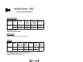
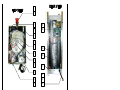
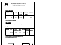
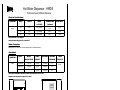
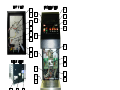
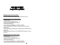
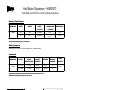
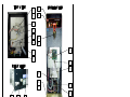
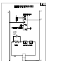
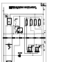
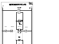
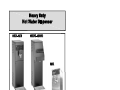
Operation Manual
NI60A 04-2002
The Hot Water Dispenser is shipped, from the factory, with the Heater Switch in the "OFF" position. DO NOT turn
the heater switch ON until the unit is primed with water. The heater switch is located at the lower back of the unit.
WATER INLET CONNECTION :
The Hot Water Dispenser is to be installed to comply with all applicable Federal, State and Local plumbing codes.
Furthermore, a quick disconnect or enough extra coiled tubing, (at least 2 times the depth of the machine) should
be installed, so that the unit can be moved for proper cleaning underneath. It is recommended that an approved
back flow prevention device, such as a double check valve, and a shut-off valve should be installed between the
Hot Water Dispenser and incoming water supply.
START - UP PROCEDURE:
CAUTION: MAKE SURE THE HEATER SWITCH, LOCATED AT THE LOWER BACK OF THE UNIT, IS IN THE
OFF POSITION.
1. Connect a ¼" diameter copper waterline to the ¼" flare water inlet.
2. Open the water shut-off valve and check connections for leaks. DO NOT over-tighten.
3. Plug in the Hot Water Dispenser into a dedicated power supply outlet.
4. Activate the Power Switch (front of unit) the water tank will begin to fill, providing the water connection is open.
The tank will fill in approximately 3-4 minutes.
5. After the tank has filled, activate the Heater Switch (toggle up, lower back of unit). Depending on the model
selected, it will take approximately 15-25 minutes for the water to heat to operating temperature.
NOTE: This procedure is for initial start - up only; however, steps 4 and 5 must be repeated should the tank be
completely drained. Steps 1 thru 5 must be repeated should the machine be drained, disconnected and reinstalled
in a new location.
THERMOSTAT ADJUSTMENT:
Remove the two (2) screws from the top cover and remove cover. The thermostat, will be visible. First, adjust the
thermostat by turning the thermostat knob either clockwise to raise the temperature, or counter clockwise to lower
the temperature. If further adjustment is required, remove knob, turn the adjustment screw, located in the center of
the thermostat shaft, counter clockwise to increase the temperature and clockwise to decrease the temperature.
Unit should be set to approximately 203°F.
WARNING: Always disconnect HWD from power supply before repairing or replacing any internal components.
DOES NOT FILL
1. Water supply off
2. Line cord not plugged in
3. Power switch off
4. Circuit breaker tripped
5. Power switch inoperative
6. Solenoid valve inoperative
7. Level control inoperative
Turn water supply on
Plug in line cord
Turn power switch on
Reset breaker
Replace power switch
Replace solenoid
Replace level control
WATER CONTINUES
TO FLOW FROM
OVERFLOW
1. Leaking solenoid valve
2. Level probe dirty
Replace solenoid
Clean or replace probe
COLD WATER
1. Heater switch in OFF position
2. Thermostat in OFF position
3. Thermostat defective
4. High limit switch defective
5. Heater element defective
6. Loose electrical connection(s)
Turn heater ON
Turn thermostat ON
Replace thermostat
Replace high limit switch
Replace heater element
Tighten all loose connections
WATER BOILS
CONTINUOUSLY
1. Thermostat out of calibration
2. Thermostat defective
Adjust thermostat as listed above
Replace thermostat
Page -1-
Hot Water Dispenser - HWD2
Tomlinson faucet Manual dispense
Electrical Specifications
MODEL NO
VOLTS
WATTS
PHASE
& CYCLES
HWD2
120
1700
1 PH. 50/60 Hz
P5-15
R5-15
240
3000
1 PH. 50/60 Hz
P6-15
R6-15
POWER CORD
(included)
RECEPTACLE
Export units add "X" to Model No.
Specify Voltage and type of line cord required.
Water Connection
Water pressure: 20 - 90 PSI (69 - 621 KPA) Supplied with ¼ OD male flare fitting
Operational
MODEL NO
VOLTS
HWD2
120 (1.7 KW)
240 (3.0 KW)
INITIAL
HEAT-UP TIME
BURST
CAPACITY
RECOVERY
GALLONS
PER HOUR
20-25 Min
1.5 Gals
10-15 Min
4.5
15-20 Min
2.0 Gals
5-10 Min
8.0
TANK
CAPACITY
2.8 Gal
Heat-up time and Dispense rate based on Inlet water temperature at 68°F and
Dispense water temperature range 165°F to 200°F
9.9
INLET
VALVE
DISPENSE
FAUCET
24.0
15.9
OVERFLOW
TUBE
POWER
CORD
DRIP
TRAY
7.9
HEATER
SWITCH
1.0
Page -2-
15.4
1
2
3
20
19
4
5
6
7
18
8
23
9
10
17
11
16
12
15
13
14
21
22
1
2
FAUCET
FAUCET SHANK
80234
77203
3
4
5
POWER SWITCH
POWER LIGHT - RED
L069A
C165A
C260A
6
7
8
HEATER LIGHT - AMBER
SILICONE SEAL 12mm (0.466 I.D.)
LEVEL CONTROL PROBE
HI-LIMIT 220° CUTOUT
M461A
K402Q
L573A
13
14
15
16
WATER INLET VALVE, 240V COIL
STRAIN RELIEF
C223A
B012A
LINE CORD, 120V 15A
LINE CORD, 240V 15A
17
18
HEATER SWITCH
WATER TANK, HWD2
WATER LEVEL CONTROL, 120V
C032A
C770A
L069A
19
20
WATER LEVEL CONTROL, 240V
40799
L398A
L599A
9
10
HEATER ELEMENT, 120V 1700W
HEATER ELEMENT, 240V 3000W
G267A
21
22
DRIP TRAY PAN
DRIP TRAY GRILL
75014
G266A
11
12
THERMOSTAT
WATER INLET VALVE, 120V
L532A
L462A
22
SILICONE HOSE 3/8ID x 16" LG
M857A
Page -3-
75015
Hot Water Dispenser - HWD3
Tomlinson faucet Manual dispense
Electrical Specifications
MODEL NO
VOLTS
WATTS
PHASE
& CYCLES
POWER CORD
(included)
RECEPTACLE
HWD3
120
1700
1 PH. 50/60 Hz
P5-15
R5-15
240
3000
1 PH. 50/60 Hz
P6-15
R6-15
Export units add "X" to Model No.
Specify Voltage and type of line cord required.
Water Connection
Water pressure: 20 - 90 PSI (69 - 621 KPA) Supplied with ¼ OD male flare fitting
Operational
MODEL NO
VOLTS
HWD3
120 (1.7 KW)
240 (3.0 KW)
INITIAL
HEAT-UP TIME
BURST
CAPACITY
RECOVERY
GALLONS
PER HOUR
20-25 Min
1.5 Gals
10-15 Min
4.5
15-20 Min
2.0 Gals
5-10 Min
8.0
TANK
CAPACITY
2.8 Gal
Heat-up time and Dispense rate based on Inlet water temperature at 68°F and
Dispense water temperature range 165°F to 200°F
24.3
23.5
IMPORTANT
- BEFORE REMOVING TOP PANEL DISCONNECT POWER
REMOVE BOTTOM PANEL
AND DRAIN TANK
9.3
9.8
1.3
7.0
Page -4-
12.0
0.7
Hot Water Dispenser - HWD5
Tomlinson faucet Manual dispense
Electrical Specifications
MODEL NO
VOLTS
WATTS
PHASE
& CYCLES
HWD5
120
1700
1 PH. 50/60 Hz
P5-15
R5-15
240
3000
1 PH. 50/60 Hz
P6-15
R6-15
240
6000
1 PH. 50/60 Hz
P6-30
R6-30
POWER CORD
(included)
RECEPTACLE
Export units add "X" to Model No.
Specify Voltage and type of line cord required.
Water Connection
Water pressure: 20 - 90 PSI (69 - 621 KPA) Supplied with ¼ OD male flare fitting
Operational
BURST
CAPACITY
RECOVERY
GALLONS
PER HOUR
30-45 Min
2.0 Gals
20-25 Min
5.0
240 (3.0 KW)
20-25 Min
3.0 Gals
15-20 Min
9.0
240 (6.0 KW)
15-20 Min
4.0 Gals
10-15 Min
14.0
MODEL NO
VOLTS
HWD5
120 (1.7 KW)
INITIAL
HEAT-UP TIME
TANK
CAPACITY
5.0 Gal
Heat-up time and Dispense rate based on Inlet water temperature at 68°F and
Dispense water temperature range 165°F to 200°F
29.0
29.8
IMPORTANT
- BEFORE REMOVING TOP PANEL DISCONNECT POWER
REMOVE BOTTOM PANEL
AND DRAIN TANK
15.3
9.3
1.3
7.0
Page -5-
12.0
0.7
22
1
8
2
21
9
3
20
4
19
5
10
6
18
7
11
3
17
16
12
7
13
15
14
23
1
2
3
24
25
HEATER ELEMENT, 120V 1700W
HEATER ELEMENT, 240V 3000W
THERMOSTAT
G267A
G266A
L532A
4
HI-LIMIT 220° CUTOUT
L573A
5
6
FLOAT SWITCH
L499A
K402Q
7
8
9
10
11
12
13
LEVEL CONTROL PROBE
SILICONE HOSE 3/8ID x 16" LG
PILOT LIGHT "HEATING"
POWER SWITCH
PILOT LIGHT "READY"
TEACH-ME TIMER
SILICONE HOSE 3/8ID x 16" LG
DRIP TRAY PAN
M857A
C165A
L155A
C072A
L576A
M857A
SA72A
Page -10-
DRIP TRAY GRILL
CONTACTOR, 2 POLE 30/40 AMP, 120V
SILICONE HOSE 3/8ID x 16" LG
SA73A
17
18
SILICONE SEAL 12mm (0.466 I.D.)
M461A
L566A
19
20
"STOP" SWITCH PB
"MANUAL" SWITCH PB
"DECANTER" SWITCH PB
L584A
"CUP" SWITCH PB
"HEATER" SWITCH
L584A
L069A
L462A
C032A
14
15
16
21
22
23
24
25
LEVEL CONTROL
WATER INLET VALVE, 120V
POWER CORD 120V
B177A
M857A
L584A
L584A
PROGRAMMABLE TIMER "TEACH ME" ADJUSTMENTS
This timer can be programmed from the push buttons to dispense different volumes of hot water.
PROGRAMMING INSTRUCTIONS FOR AUTOMATIC DISPENSE
1. Turn Power Switch ON.
2. PRESS and HOLD [red] STOP Button with one hand.
3. PRESS and HOLD [green] DISPENSE Button with other hand.
4. RELEASE [red] STOP Button ONLY.
5. Continue to HOLD [green] DISPENSE Button for 5 SECONDS, then RELEASE.
6. PRESS and RELEASE [green] DISPENSE Button. Product begins dispensing. When it reaches the
"DESIRED VOLUME",
7. PRESS and RELEASE [green] DISPENSE Button to SET "DESIRED VOLUME". DISPENSE Button can be
"jogged" to top off.
8. PRESS and RELEASE [red] STOP button to LOCK IN "DESIRED VOLUME". Repeat steps 1 to 8 for each
Dispense Button.
PROGRAMMING INSTRUCTIONS FOR MANUAL DISPENSE
1. Turn Power Switch ON.
2. PRESS and HOLD [red] STOP Button with one hand.
3. PRESS and HOLD [green] DISPENSE Button with other hand.
4. RELEASE [red] STOP Button ONLY.
5. Continue to HOLD [green] DISPENSE Button for 5 SECONDS, then RELEASE.
6. PRESS and RELEASE [red] STOP Button. Unit is in MANUAL DISPENSE mode.
Page -7-
Hot Water Dispenser - HWD3PC
Push Button with Portion control or Manual dispense
Electrical Specifications
MODEL NO
VOLTS
WATTS
PHASE
& CYCLES
120
1700
1 PH. 50/60 Hz
P5-15
R5-15
240
3000
1 PH. 50/60 Hz
P6-15
R6-15
HWD3PC
POWER CORD
(included)
RECEPTACLE
Export units add "X" to Model No.
Specify Voltage and type of line cord required.
Water Connection
Water pressure: 20 - 90 PSI (69 - 621 KPA) Supplied with ¼ OD male flare fitting
Operational
MODEL NO
HWD3PC
VOLTS
INITIAL
HEAT-UP TIME
BURST
CAPACITY
RECOVERY
GALLONS
PER HOUR
120 (1.7 KW)
20-25 Min
1.5 Gals
10-15 Min
4.5
240 (3.0 KW)
15-20 Min
2.0 Gals
5-10 Min
6.0
TANK
CAPACITY
2.8 Gal
Heat-up time and Dispense rate based on Inlet water temperature at 68°F and
Dispense water temperature range 165°F to 200°F
24.3
23.5
9.8
9.3
1.3
7.0
Page -8-
12.0
0.7
Hot Water Dispenser - HWD5PC
Push Button with Portion control or Manual dispense
Electrical Specifications
MODEL NO
VOLTS
WATTS
PHASE
& CYCLES
120
1700
1 PH. 50/60 Hz
P5-15
R5-15
240
3000
1 PH. 50/60 Hz
P6-15
R6-15
240
6000
1 PH. 50/60 Hz
P6-30
R6-30
HWD5PC
POWER CORD
(included)
RECEPTACLE
Export units add "X" to Model No.
Specify Voltage and type of line cord required.
Water Connection
Water pressure: 20 - 90 PSI (69 - 621 KPA) Supplied with ¼ OD male flare fitting
Operational
MODEL NO
HWD5PC
VOLTS
INITIAL
HEAT-UP TIME
BURST
CAPACITY
RECOVERY
GALLONS
PER HOUR
120 (1.7 KW)
30-45 Min
2.0 Gals
20-25 Min
5.0
240 (3.0 KW)
20-25 Min
3.0 Gals
15-20 Min
9.0
240 (6.0 KW)
15-20 Min
4.0 Gals
10-15 Min
14.0
TANK
CAPACITY
5.0 Gal
Heat-up time and Dispense rate based on Inlet water temperature at 68°F and
Dispense water temperature range 165°F to 200°F
29.0
29.7
15.3
9.3
1.3
7.0
Page -9-
12.0
0.7
8
1
9
2
3
4
5
10
6
11
18
7
3
17
16
12
13
15
14
7
19
20
21
1
HEATER ELEMENT, 120V 1700W
G267A
14
DRIP TRAY GRILL
SA73A
2
HEATER ELEMENT, 230V 6000W
THERMOSTAT
G281A
L532A
L573A
15
CONTACTOR, 2 POLE 30/40 AMP, 120V
SILICONE HOSE 3/8ID x 16" LG
B177A
M857A
M461A
3
4
5
6
7
8
9
10
11
12
13
HI-LIMIT 220° CUTOUT
FLOAT SWITCH
LEVEL CONTROL PROBE
L499A
K402Q
SILICONE HOSE 3/8ID x 16" LG
PILOT LIGHT "HEATING"
M857A
C165A
POWER SWITCH
FAUCET
SHANK SUB-ASSEMBLY
SILICONE HOSE 3/8ID x 16" LG
DRIP TRAY PAN
L155A
80234
D094Q
M857A
SA72A
Page -6
16
17
18
19
20
21
SILICONE SEAL 12mm (0.466 I.D.)
LEVEL CONTROL
"HEATER" SWITCH
WATER INLET VALVE, 120V
POWER CORD 120V
L566A
L069A
L462A
C032A
L1
N
L1
HEATER
LIGHT
WHT
L1
HEATER SWITCH
L1
POWER
LIGHT
POWER
SWITCH
WHT
BLK
N
L1
CECILWARE CORPORATION
CECILWARE CORPORATION
HI-LIMIT
THERMOSTAT
CONTACTOR
HEATER SW
HEATING
WATER INLET VALVE
LEVEL
CONTROL
FLOAT SWITCH
WATER LEVEL PROBE
CECILWARE CORPORATION