1
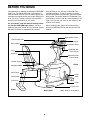
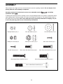
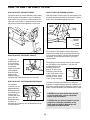
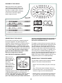
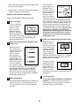
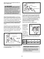
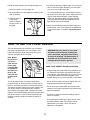
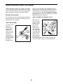
¨
Model No. PFRX35390
Serial No.
USER'S MANUAL
Serial
Number
Decal
QUESTIONS?
As a manufacturer, we are
committed to providing complete customer satisfaction. If
you have questions, or if there
are missing parts, we will guarantee complete satisfaction
through direct assistance from
our factory.
TO AVOID UNNECESSARY
DELAYS, PLEASE CALL
DIRECT TO OUR TOLL-FREE
CUSTOMER HOT LINE. The
trained technicians on our
customer hot line will provide
immediate assistance, free of
charge to you.
CUSTOMER HOT LINE:
1-800-999-3756
Mon.ÐFri., 6 a.m.Ð6 p.m. MST
Patent Pending
CAUTION
Read all precautions and instructions in this manual before using
this equipment. Keep this manual for future reference.
Visit our website at
www.proform.com
new products, prizes,
fitness tips, and much more!
TABLE OF CONTENTS
CAUTION DECAL PLACEMENT . . . . . . . . . . . . . . . . . . . . . . . . . . . . . . . . . . . . . . . . . . . . . . . . . . . . . . . . . . .2
IMPORTANT PRECAUTIONS . . . . . . . . . . . . . . . . . . . . . . . . . . . . . . . . . . . . . . . . . . . . . . . . . . . . . . . . . . . . .3
BEFORE YOU BEGIN . . . . . . . . . . . . . . . . . . . . . . . . . . . . . . . . . . . . . . . . . . . . . . . . . . . . . . . . . . . . . . . . . . .4
ASSEMBLY . . . . . . . . . . . . . . . . . . . . . . . . . . . . . . . . . . . . . . . . . . . . . . . . . . . . . . . . . . . . . . . . . . . . . . . . . . .5
EXPLODED DRAWING . . . . . . . . . . . . . . . . . . . . . . . . . . . . . . . . . . . . . . . . . . . . . . . . . . . . . . . . . . . . . . . . .10
PART LIST . . . . . . . . . . . . . . . . . . . . . . . . . . . . . . . . . . . . . . . . . . . . . . . . . . . . . . . . . . . . . . . . . . . . . . . . . . .12
HOW TO USE THE LIGHT CYCLE . . . . . . . . . . . . . . . . . . . . . . . . . . . . . . . . . . . . . . . . . . . . . . . . . . . . . . . .13
HOW TO USE THE PULSE SENSOR . . . . . . . . . . . . . . . . . . . . . . . . . . . . . . . . . . . . . . . . . . . . . . . . . . . . . .17
MAINTENANCE AND STORAGE . . . . . . . . . . . . . . . . . . . . . . . . . . . . . . . . . . . . . . . . . . . . . . . . . . . . . . . . . .18
CONDITIONING GUIDELINES . . . . . . . . . . . . . . . . . . . . . . . . . . . . . . . . . . . . . . . . . . . . . . . . . . . . . . . . . . . .19
ORDERING REPLACEMENT PARTS . . . . . . . . . . . . . . . . . . . . . . . . . . . . . . . . . . . . . . . . . . . . . . . .Back Cover
LIMITED WARRANTY . . . . . . . . . . . . . . . . . . . . . . . . . . . . . . . . . . . . . . . . . . . . . . . . . . . . . . . . . . .Back Cover
CAUTION DECAL PLACEMENT
The decals shown below have been placed on the Light Cycle. If one of the decals is missing, or if it
is not legible, please call our Customer Service Department toll-free at 1-800-999-3756 to order a free
replacement decal. Apply the decal in the location shown.
Do not allow children on or
around machine.
Keep hands and feet away
from moving parts and contact
points.
C AU T I O N
Read owner's manual and
follow instructions.
S U R FAC E M AY B E H OT
KEEP CLEAR
2
IMPORTANT PRECAUTIONS
WARNING: To reduce the risk of serious injury, read the following important precautions before using the PROFORM¨ Light Cycle.
1. Read all instructions in this manual before
using the Light Cycle.
12. If you have serious back injuries or chronic
back pain, consult a physician before using
the lumbar cushion.
2. Use the Light Cycle only as described in
this manual.
13. Do not use the lumbar cushion if you are
pregnant or wearing a pacemaker or any
other electrical implant.
3. It is the responsibility of the owner to ensure
that all users of the Light Cycle are adequately informed of all precautions.
14. The magnets in the lumbar cushion are not
being sold as medical devices.
4. The Light Cycle is intended for in-home use
only. Do not use the Light Cycle in a commercial, rental, or institutional setting.
15. The light therapy pod becomes hot during
use. Allow the light therapy pod to cool
before touching it.
5. Use the Light Cycle indoors on a level surface. Keep the Light Cycle away from moisture and dust. Place a mat under the Light
Cycle to protect the floor or carpet.
16. Do not place towels, clothing, or any other
objects on the light therapy pod.
6. Inspect and tighten all parts regularly.
Replace any worn parts immediately.
17. Although your eyes must be open to benefit
from light therapy, do not look directly into
the lights on the light therapy pod.
7. Keep children under the age of 12 and pets
away from the Light Cycle at all times.
18. Do not drop or insert any object into any
opening.
8. The Light Cycle should not be used by persons weighing more than 250 pounds.
19. The pulse sensor is not a medical device.
Various factors may affect the accuracy of
heart rate readings. The pulse sensor is
intended only as an exercise aid in determining heart rate trends in general.
9. Wear appropriate clothing when exercising;
do not wear loose clothing that could
become caught on the Light Cycle. Always
wear athletic shoes for foot protection.
20. Always keep your back straight when using
the Light Cycle. Do not arch your back.
10. When connecting the power cord on the
light therapy pod (see HOW TO PLUG IN
THE POWER CORD on page 16), plug the
power cord into a grounded circuit capable
of carrying 15 or more amps. No other appliance should be on the same circuit.
21. If you feel pain or dizziness at any time
while exercising, stop immediately and
begin cooling down.
22.
DANGER: Always unplug the light
therapy pod immediately after using it and
before cleaning.
11. Keep the power cord away from heated
surfaces.
WARNING: Before beginning this or any exercise program, consult your physician.
This is especially important for persons over the age of 35 or persons with pre-existing health problems. Read all instructions before using. ICON assumes no responsibility for personal injury or
property damage sustained by or through the use of this product.
SAVE THESE INSTRUCTIONS
3
BEFORE YOU BEGIN
Congratulations for selecting the innovative PROFORM¨
Light Cycle. The PROFORM Light Cycle features a
semi-recumbent exercise cycle, a lumbar support with
massage and magnet therapy, and a light therapy pod
to let you enjoy a variety of exercise and relaxation
options in the convenience of your home.
through Friday, 6 a.m. until 6 p.m. Mountain Time
(excluding holidays). To help us assist you, please
mention the product model number and serial number
when calling. The model number is PFRX35390. The
serial number can be found on a decal attached to the
Light Cycle (see the front cover of this manual for the
location of the decal).
For your benefit, read this manual carefully before
you use the PROFORM Light Cycle. If you have
additional questions, please call our Customer Service
Department toll-free at 1-800-999-3756, Monday
Before reading further, please look at the drawing
below and familiarize yourself with the parts that are
labeled.
Water Bottle Holder*
Light Therapy Pod
Console
Book Holder
Resistance Knob
Handlebar with
Pulse Sensor
Seat
Backrest
Ballast Box with
Power Switch
Lumbar Cushion
FRONT
Adjustment Bulb
Seat Frame
Pedal
Strap
Seat Handle
Lock Knob
Pedal
Power Cord
BACK
RIGHT SIDE
4
*Water bottle is not included
ASSEMBLY
Place all parts of the Light Cycle in a cleared area and remove the packing materials. Do not dispose of the
packing materials until assembly is completed.
Assembly requires the included tools and your own adjustable wrench
screwdriver
.
and phillips
To identify the small parts used in assembly, refer to the part drawings below. The number in parenthesis below
each drawing refers to the key number of the part, from the part list on page 12. The second number refers to
the quantity used in assembly. Note: Some small parts may have been pre-attached for shipping. If a part
is not in the parts bag, check to see if it has been pre-assembled.
M6 Split Washer (67)Ð4
M10 Split Washer (26)Ð3
M6 Nylon Locknut (66)Ð4
M10 Nylon Locknut (72)Ð4
#8 x 5/8Ó Screw (22)Ð4
M6 x 16mm Hex Head Screw (24)Ð8
M6 x 38mm Button Head Bolt (18)Ð4
M10 Flat Washer (71)Ð4
M4 x 16mm Screw (34)Ñ1
M6 x 25mm Hex Head Screw (14)Ð4
M10 x 25mm Button Head Screw (25)Ð3
M10 x 105mm Button Head Bolt (70)Ð4
5
1. Loosen the Lock Knob (68) on the right side of the
Frame (1). Slide the Seat Frame (3) out until it
stops. Tighten the Lock Knob.
1
1
68
3
2. Attach the Upright (2) to the Frame (1) with three
M10 x 25mm Button Head Screws (25) and three
M10 Split Washers (26). Be careful not to pinch
the Reed Switch Wire (13) or the Resistance
Cable (10).
2
2
25
26
26
25
25
13
10
1
3. The light therapy pod requires two GX 24 Q-3 Base
Light Tubes (88). Remove the four #8 x 3/8Ó Screws
(97) from the back of the Left Light Cover (91).
Remove the Left Light Cover. Insert a Light Tube
into the Light Fixture (87). Reattach the Left Light
Cover with the #8 x 3/8Ó screws.
3
88
Install a Light Tube (88) into the right side of the light
therapy pod in the same manner.
91
97
87
4. Route both Extension Wires (41) up through the
Upright (2) as shown.
4
82
Attach the Handlebar (4) and the Light Frame (82) to
the Upright (2) with two M6 x 25mm Hex Head
Screws (14) and two M6 Split Washers (67), but do
not tighten the Screws yet. Make sure that the
Screws are in the indicated holes. Note: Two
more Screws will be attached in step 6.
14
67
41
14
67
Remove the backing from the Fastener Strip (77) and
press it onto the Upright (2) in the position shown.
Firmly press the Ballast Box (81) onto the Fastener
Strip.
6
81
77
4
2
5. Connect the Reed Switch Wire (13) and the two
Extension Wires (41) to the corresponding wires on
the Console (8).
5
8
9
Console
Wires
If your Console (8) has a ground wire, attach it to
the Upright (2) with an M4 x 16mm Screw (34).
Ground
Wire
34
13 41
Next, attach the Console (8) to the Upright (2) with
four #8 x 5/8Ó Screws (22).
10
Press the Resistance Knob (9) onto the Resistance
Control (10). Be sure that the mark on the Knob is
correctly aligned.
22
2
22
6. Finish attaching the Handlebar (4) and the Light
Frame (82) to the Upright (2) with two more M6 x
25mm Hex Head Screws (14) and two more M6
Split Washers (67). Tighten all four Hex Head
Screws.
6
14
67
82
Remove the backing from the Cord Clips (95) and
and press them onto the exercise cycle in the indicated locations. Insert the Power Cord (73) into the
Cord Clips. Make sure that the Power Cord cannot get caught on the pedals while you are exercising.
7. Attach the Seat Bracket (69) to the Seat Frame (3)
with four M10 x 105mm Button Head Bolts (70), four
M10 Flat Washers (71), and four M10 Nylon
Locknuts (72).
14
4
67
2
73
95
70
7
69
3
71
72
8. Attach the Seat (16) to the Seat Bracket (69) with
four M6 x 16mm Hex Head Screws (24).
8
71
16
69
24
7
9. Attach a Seat Handle (17) to the Seat Bracket (69)
with two M6 x 38mm Button Head Bolts (18) and
two M6 Nylon Locknuts (66).
9
17
Attach the other Seat Handle (17) to the Seat
Bracket (69) in the same manner.
69
66
17
10. Attach the Backrest (15) to the Seat Bracket (69)
with four M6 x 16mm Hex Head Screws (24).
18
10
15
69
24
11. Identify the Left Pedal (45) (there is an ÒLÓ on the
Left Pedal for identification). Using an adjustable
wrench, firmly tighten the Left Pedal counterclockwise into the left arm of the Crank (29).
11
27
Firmly tighten the Right Pedal (not shown) clockwise into the right arm of the Crank (29).
45
Adjust the Pedal Strap (27) on the Left Pedal (45) to
the desired position. Press the Pedal Strap onto the
tab on the Left Pedal.
Adjust the Pedal Strap on the Right Pedal (not
shown) in the same manner.
8
Tab
29
12. The Console (8) requires either two or three ÒAAÓ
batteries (not included); alkaline batteries are
recommended. Open the battery cover (not shown)
on the back of the Console. Press the batteries into
the battery clip. Make sure that the negative (Ð)
ends of the batteries are touching the springs.
Close the battery cover. Note: If the battery clip
holds three batteries, you must insert three batteries.
12
8
Batteries
Battery
Clip
13. The Lumbar Cushion (94) requires two ÒDÓ batteries
(not included); alkaline batteries are recommended.
Open the zipper on the back of the Lumbar
Cushion. Press the batteries into the battery clip.
Make sure that the negative (Ð) ends of the batteries are turned away from the motor. Close the
zipper.
13
Battery
Clip
Zipper
94
Batteries
Motor
14. Slide the Lumbar Cushion (94) over the Backrest
(15) as shown.
14
15
94
Elastic
Strap
15. Make sure that all parts are properly tightened
before you use the Light Cycle. Note: Some
hardware may be left over after assembly is
completed. Place a mat under the Light Cycle to
protect the floor or carpet.
9
HOW TO USE THE LIGHT CYCLE
HOW TO ADJUST THE SEAT FRAME
HOW TO USE THE LUMBAR CUSHION
The Seat Frame (3) can be adjusted to the position
that is the most comfortable for you. To adjust the
Seat Frame, first loosen the Lock Knob (68) on the
right side of the Frame (1). Slide the Seat Frame to
the desired position and retighten the Lock Knob.
Slide the Lumbar Cushion (94) over the Backrest (15)
as shown. Adjust the position of the Lumbar Cushion
until it feels comfortable against your back.
On/Off
Switch
1
68
94
15
Elastic
Strap
Release
Button
3
Hand
Pump
The firmness of the Lumbar Cushion (94) can be
adjusted as desired using the attached hand pump.
To increase the firmness, squeeze the hand pump
repeatedly. To decrease the firmness, press the
release button.
HOW TO ADJUST THE PEDAL STRAPS
To adjust the
Pedal Straps (27,
31 [not shown]),
27
first pull the ends
of the Pedal
Straps off the tabs
on the pedals.
Tab
Slide the Pedal
Straps to the
desired positions
and press the Pedal Straps back onto the tabs.
The massager in the Lumbar Cushion (94) requires
two ÒDÓ batteries (not included). If you have not
installed batteries, see
assembly step 13 on
page 9. To turn on the
On
massager, press the top
of the on/off switch on the
Lumbar Cushion. Press
Off
the bottom of the switch
to turn off the massager.
HOW TO ADJUST THE PEDALING RESISTANCE
The lumbar cushion also features four 800-gauss
magnets for magnet therapy. Research indicates that
the positive energy emitted from bipolar magnets may
help to increase circulation and eliminate minor aches.
The pedaling
resistance can be
8
adjusted with the
Resistance Knob
(9) located on the
9
Console (8). To
increase the resistance, turn the
Resistance Knob
clockwise; to
decrease the resistance, turn the Resistance Knob
counterclockwise.
CAUTION: If you have serious back injuries
or chronic back pain, consult a physician
before using this product.
CAUTION: Do not use this product if you are
pregnant or wearing a pacemaker or any
other electrical implant. Magnets are not
being sold as medical devices.
13
DIAGRAM OF THE CONSOLE
Before the console can be operated,
ÒAAÓ batteries must be installed. If you
have not installed batteries, see assembly step 12 on page 9. Note: If there is
a thin sheet of clear plastic on the face
of the console, remove the plastic
before using the console.
DESCRIPTION OF THE CONSOLE
get pace, especially during the first few months of
your exercise program. Be sure to exercise at a
pace that is comfortable for you.
The innovative console offers a manual mode and
three pacer programs. The pacer programs are
designed to help you achieve your exercise goals by
pacing your exercise. The programs include an 18
MPH/90 RPM program, a 12 MPH/60 RPM program,
and a 6 MPH/30 RPM program. The console also features five monitor modes that provide continuous exercise feedback. Note: On some consoles the programs are listed in MPH and on others in RPM.
Both sets of programs are identical.
The graphs on the left side of the console show how
the target pace will change during each program (see
the drawing above). Each graph is divided into ten
columns, and each column represents 1/10 of a mile.
The bars in each column show what the target pace
will be during that 1/10 of a mile. For example, in the
first column of the 12 MPH/60 RPM graph, there is
one bar. This shows that during the first 1/10 of a mile
in this program, the target pace will be 6 MPH (30
RPM). In the second column, there are two bars, indicating that the pace is now 12 MPH (60 RPM).
HOW THE PACER PROGRAMS OPERATE
When you use a
Actual
Target
pacer program, an
Pace
Pace
indicator will light on
each track of the
P.A.C.E.R.
display. The outer
track shows a target
pace; the inner
track will show your
actual pace. The
target pace will
change periodically during the 18 MPH/90 RPM and
12 MPH/60 RPM programs; as the target pace
changes, simply adjust your pace to keep both indicators even. Important: The target pace is a goal
pace. Your actual pace may be slower than the tar-
DESCRIPTION OF THE MONITOR MODES
The five monitor modes provide continuous exercise
feedback. The modes are described below.
¥ SpeedÑThis mode shows your pace, in miles per
hour.
¥ TimeÑThis mode counts the length of time you
have exercised. Note: If you stop exercising for ten
seconds or longer, the time mode will pause.
¥ Distance (DIST)ÑThis mode shows the total number of miles you have cycled, up to 999. The display will then reset to zero and continue counting.
14
¥ LapsÑThis mode shows the number of quarter-mile
laps you have completed.
If you selected a
Target
pacer program, two
Pace
indicators on the
P.A.C.E.R. track will
Actual
light. The indicator on
Pace
the inner track will
show your actual
pace. The indicator
on the outer track will
move around the track at the programmed pace.
As you exercise, adjust your pace so that the indicators on the inner and outer tracks remain even.
As the program progresses, the target pace will
change periodically; as the target pace changes,
you should also adjust your pace. Important: The
target pace is a goal pace. Your actual pace
may be slower than the target pace, especially
during the first few months of your exercise
program. Be sure to exercise at a pace that is
comfortable for you.
¥ Calories (CAL)ÑThis mode shows the approximate
number of calories you have burned.
STEP-BY-STEP CONSOLE OPERATION
Follow the steps below to operate the console.
1
Turn on the power
To turn on the power,
press the on/reset
button or simply
begin exercising.
When the power is
turned on, the entire
display will appear for
two seconds. The console will then be ready for
use. Note: If batteries were just installed, the
power will already be on.
2
4
When the power is
turned on, the console will scan through
the five modes automatically. A flashing
mode indicator will
Mode Indicator
show which mode is
currently displayed.
When the Laps mode is displayed, an ÒLÓ will also
appear. If desired, the display can be reset by
pressing the on/reset button.
Select one of the three pacer programs or the
manual mode
When the power is
first turned on, the
console will be in the
manual mode. To
select one of the
pacer programs,
repeatedly press the
program button. The
program indicator will
show which program
you have selected.
The programs will be
selected in the following order: the manual mode,
the 6 MPH/30 RPM program, the 12 MPH/60
RPM program, and the 18 MPH/ 90 RPM program. Note: Once you select a pacer program,
you can reselect the manual mode by repeatedly
pressing the program button.
3
Follow your progress with the monitor modes
The Light Cycle also
features an innovative handgrip pulse
sensor. The pulse
display allows you to
monitor your heart
rate during your workout. To use the pulse sensor,
see page 17.
5
Begin your workout
Turn off the power
To turn off the power, simply wait for about six
minutes. If the pedals are not moved and the
console buttons are not pressed for six minutes,
the power will turn off automatically.
If you selected the manual mode, one indicator on
the inner P.A.C.E.R. track will light. As you exercise, this indicator will move around the quartermile track.
15
HOW TO PLUG IN THE POWER CORD ON THE
LIGHT THERAPY POD
2
Grounded Outlet Box
Adapter
DANGER:
Improper connection
of the equipment-grounding conductor can
result in an increased risk of electric shock.
Check with a qualified electrician or service
representative if you are in doubt as to
whether the product is properly grounded. Do
not modify the plug provided with the productÑif it will not fit the outlet, have a proper
outlet installed by a qualified electrician.
Grounding Pin
Grounding Plug
Lug
Metal Screw
The green-colored rigid ear, lug, or the like extending
from the adapter must be connected to a permanent
ground such as a properly grounded outlet box cover.
Whenever the adapter is used it must be held in place
by a metal screw. Some 2-pole receptacle outlet box
covers are not grounded. Contact a qualified
electrician to determine if the outlet box cover is
grounded before using an adapter.
This product must be grounded. If it should malfunction or break down, grounding provides a path of
least resistance for electric current to reduce the risk
of electric shock. This product is equipped with a cord
having an equipment-grounding conductor and a
grounding plug. Plug the power cord into an appropriate outlet that is properly installed and grounded in accordance with all local codes and ordinances.
HOW TO USE THE LIGHT THERAPY POD
The light therapy
pod allows you
to enjoy the benefits of light therapy while you
exercise or while
you simply relax.
This product is for use on a nominal 120-volt circuit,
and has a grounding plug that looks like the plug
illustrated in drawing 1 below. A temporary adapter
that looks like the adapter illustrated in drawing 2 may
be used to connect the power cord to a 2-pole receptacle as shown in drawing 2 if a properly grounded
outlet is not available.
Light
Therapy
Pod
The effectiveness of light therapy depends on
two factors: your
distance from the
light and the length of time you use the light. The chart
below shows the intensity of the lights at different distances.
1
Grounded Outlet Box
Grounding Plug
Light Cycle
Power Cord
Distance
Grounding Pin
Lux
6Ó
12Ó
18Ó
24Ó
10,000
3,200
2,500
1,500
Grounded Outlet
The temporary adapter should be used only until a
properly grounded outlet (drawing 1) can be installed
by a qualified electrician.
WARNING: Before beginning this or any light
therapy program, consult your physician.
WARNING: The light therapy pod becomes
hot during use. Allow the light therapy pod
to cool before touching it.
16
4. To enjoy the benefits of light therapy, it is not necessary to look at the lights. However, you must open
your eyes so that light can enter.
Follow the steps below to use the light therapy pod.
1. Plug in the power cord (see page 16).
2. Sit on the Light Cycle and adjust the position of the
seat as desired.
It is recommended that you use the lights for 30 to
60 minutes three times per week to begin with. This
may be done while exercising or while relaxing.
When you are familiar with the light therapy pod,
you may adjust the length and frequency of your
light therapy sessions as desired.
3. Press the bottom
of the on/off
switch on the ballast box to turn on
the lights.
5. When you are finished using the light therapy pod,
press the top of the on/off switch on the ballast box
to turn off the lights. In addition, unplug the power
cord.
On/Off
Switch
HOW TO USE THE PULSE SENSOR
The convenient pulse sensor allows you to measure
your heart rate periodically. You can measure your
heart rate before you begin exercising, during your
workout, and again when you finish.
Note: Before
the pulse sensor can be
used, the protective vinyl
covering must
be peeled off
the metal contacts on the
front and rear
of each pulse
grip.
WARNING:The pulse sensor is not a medical device. Various factors, including the
userÕs movement, may affect the accuracy
of heart rate readings. The pulse sensor is
intended only as an exercise aid in determining heart rate trends in general.
HAND PULSE SENSOR TROUBLE-SHOOTING
¥ Avoid moving your hands while using the pulse sensor. Excessive movement may interfere with heart
rate readings. If the pulse sensor is not used correctly, the heart indicator will flash repeatedly in the
PULSE display but your heart rate will not be shown.
Metal
Contacts
¥ Do not hold the metal contacts too tightly; doing so
may interfere with heart rate readings.
To use the pulse sensor, first make sure that the
power is turned on. Stop exercising, rest both feet on
the floor, and place your hands on the metal contacts.
Your palms must be resting on the inner contacts and
your fingers must be touching the outer contacts.
Avoid moving your hands. After a moment, the heart
indicator in the PULSE display will flash and your heart
rate will be shown. For the most accurate heart rate
reading, continue to hold the contacts for about 15
seconds.
¥ Do not move your hands while you hold the metal
contacts; your muscle movement may interfere with
heart rate readings.
¥ For the most accurate heart rate reading, wait for
about 15 seconds.
¥ For optimal performance of the pulse sensor, keep
the metal contacts clean. The contacts can be
cleaned with a soft clothÑnever use alcohol,
abrasives, or chemicals.
17
MAINTENANCE AND STORAGE
driver in one of the slots in the slotted bearing nut.
Lightly tap the screwdriver with a hammer to turn the
slotted bearing nut counterclockwise until the arms
are no longer loose. Do not overtighten the slotted
bearing nut. When the slotted bearing nut is properly
tightened, tighten the Crank Nut.
Inspect and tighten all parts of the Light Cycle regularly. The Light Cycle can be cleaned with a soft, damp
cloth. To prevent damage to the console, keep liquids
away and keep the console out of direct sunlight.
BATTERY REPLACEMENT
HOW TO STORE THE EXERCISE CYCLE
If the console does not function properly, the batteries
should be replaced. To replace the batteries, refer to
assembly step 12 on page 9.
When the exercise cycle is not
1
in use, it can be
68
folded for compact storage.
Refer to the
drawing at the
right. Loosen the
Lock Knob (68)
3
on the right side
of the Frame (1).
Slide the Seat
Frame (3) as far
into the Frame
as it will go. Tighten the Lock Knob. Store the exercise cycle indoors, away from moisture and dust.
CRANK ADJUSTMENT
If the arms of the
Crank (29)
become loose,
they should be
tightened in
order to prevent
excessive wear.
Loosen the
Crank Nut (35)
on the left arm of
the Crank. Place
the end of a
standard screw-
Slotted
Bearing
Nut
Crank
Nut
29
18
CONDITIONING GUIDELINES
The following guidelines will help you to plan your
exercise program. Remember that proper nutrition and
adequate rest are essential for successful results.
WARNING: Before beginning this or any
exercise program, consult your physician.
This is especially important for individuals
over the age of 35 or individuals with preexisting health problems.
WHY EXERCISE?
Exercise has proven essential for good health and
general well-being. Regular participation in a wellrounded exercise program results in a stronger and
more efficient heart, improved respiratory function,
increased stamina and endurance, better weight management and body fat control, increased ability to deal
with stress, and greater self-esteem and confidence.
EXERCISE INTENSITY
To maximize the benefits of exercising, it is important
to exercise with the proper intensity. The proper intensity level can be found by using your heart rate as a
guide. For effective aerobic exercise, your heart rate
should be maintained at a level between 70% and
85% of your maximum heart rate as you exercise.
This is known as your training zone. You can find
UNCONDITIONED CONDITIONED
20
138Ð167
133Ð162
25
136Ð166
132Ð160
30
135Ð164
130Ð158
35
134Ð162
129Ð156
40
132Ð161
127Ð155
45
131Ð159
125Ð153
50
129Ð156
124Ð150
55
127Ð155
122Ð149
60
126Ð153
121Ð147
65
125Ð151
119Ð145
70
123Ð150
118Ð144
75
122Ð147
117Ð142
80
120Ð146
115Ð140
85
118Ð144
114Ð139
To measure your heart rate, use the pulse sensor in
the handlebar. You can also measure your pulse by
placing two fingers
on your wrist. Stop
exercising and
take a six-second
heartbeat count.
Multiply the result
by ten to find your
heart rate. (A sixsecond count is
used because
your heart rate
drops quickly when you stop exercising.) If your heart
rate is too high, decrease the intensity of your exercise. If your heart rate is too low, increase the intensity
of your exercise.
WORKOUT GUIDELINES
A well-rounded workout includes the following three
phases:
A warm-up phase, lasting 5 to 10 minutes. Begin with
slow, controlled stretches, and progress to more rhythmic stretches. This will increase the body temperature,
heart rate, and circulation in preparation for strenuous
exercise.
TRAINING ZONE (BEATS/MIN.)
AGE
your training zone in the table below. Training zones
are listed according to age and physical condition.
During the first few months of your exercise program,
keep your heart rate near the low end of your training
zone as you exercise. After a few months of regular
exercise, your heart rate can be increased gradually
until it is near the middle of your training zone as you
exercise.
A cardiovascular phase, including 20 to 30 minutes
of exercising with your heart rate in your training zone.
A cool-down phase, consisting of 5 to 10 minutes of
stretching. Thorough stretching offsets muscle contractions and other problems caused when you stop
exercising suddenly. Stretching for increased flexibility
is often most effective during this phase. This phase
should leave you relaxed and comfortably tired.
To maintain or improve your condition, complete three
workouts each week, with at least one day of rest
between workouts. After a few months of regular exercise, you may complete up to five workouts each
week, if desired. Find the best time of day for your
workouts, and then stick with it. Remember, the key to
success is to make exercise a regular and enjoyable
part of your everyday life.
19
ORDERING REPLACEMENT PARTS
To order replacement parts, call our Customer Service Department toll-free at 1-800-999-3756, Monday through
Friday, 6 a.m. until 6 p.m. Mountain Time (excluding holidays). To help us assist you, please be prepared to give
the following information:
¥ The MODEL NUMBER of the product (PFRX35390)
¥ The NAME of the product (PROFORM¨ Light Cycle)
¥ The SERIAL NUMBER of the product (see the front cover of this manual)
¥ The KEY NUMBER and DESCRIPTION of the part(s) (see the EXPLODED DRAWING and PART LIST
attached in the center of this manual).
PROFORM¨ is a registered trademark of ICON Health & Fitness, Inc.
LIMITED WARRANTY
ICON Health & Fitness, Inc. (ICON), warrants this product to be free from defects in workmanship and
material, under normal use and service conditions, for a period of ninety (90) days from the date of purchase. This warranty extends only to the original purchaser. ICON's obligation under this warranty is limited to replacing or repairing, at ICON's option, the product through one of its authorized service centers.
All repairs for which warranty claims are made must be pre-authorized by ICON. This warranty does not
extend to any product or damage to a product caused by or attributable to freight damage, abuse, misuse, improper or abnormal usage or repairs not provided by an ICON authorized service center, products
used for commercial or rental purposes, or products used as store display models. No other warranty
beyond that specifically set forth above is authorized by ICON.
ICON is not responsible or liable for indirect, special or consequential damages arising out of or in connection with the use or performance of the product or damages with respect to any economic loss, loss
of property, loss of revenues or profits, loss of enjoyment or use, costs of removal, installation or other
consequential damages of whatsoever nature. Some states do not allow the exclusion or limitation of incidental or consequential damages. Accordingly, the above limitation may not apply to you.
The warranty extended hereunder is in lieu of any and all other warranties and any implied warranties of
merchantability or fitness for a particular purpose is limited in its scope and duration to the terms set forth
herein. Some states do not allow limitations on how long an implied warranty lasts. Accordingly, the above
limitation may not apply to you.
This warranty gives you specific legal rights. You may also have other rights which vary from state to state.
ICON HEALTH & FITNESS, INC., 1500 S. 1000 W., LOGAN, UT 84321-9813
Part No. 160464 R1099A
Printed in China © 1999 ICON Health & Fitness, Inc.
PART LISTÑModel No. PFRX35390
Key No. Qty.
1
2
3
4
5
6
7
8
9
10
11
12
13
14
15
16
17
18
19
20
21
22
23
24
25
26
27
28
29
30
31
32
33
34
35
36
37
38
39
40
41
42
43
44
45
46
47
48
49
50
1
1
1
1
2
1
1
1
1
1
4
4
1
4
1
1
2
4
2
1
6
21
2
8
3
3
1
1
1
1
1
1
2
1
4
2
2
2
4
2
2
1
1
1
1
2
2
5
1
1
Description
R1099A
Key No. Qty.
Frame
Upright
Seat Frame
Handlebar
Pulse Grip
Left Side Shield
Right Side Shield
Console
Resistance Knob
Resistance Cable/Control
M5 x 30mm Screw
M5 Nut
Reed Switch/Wire
M6 x 25mm Hex Head Screw
Backrest
Seat
Seat Handle
M6 x 38mm Button Head Bolt
Foam Handle Grip
1Ó x 3Ó Endcap
Tree Fastener
#8 x 5/8Ó Screw
#8 x 3/8Ó Screw
M6 x 16mm Hex Head Screw
M10 x 25mm Button Head Screw
M10 Split Washer
Left Pedal Strap
Right Pedal
Crank/Pulley
Bearing Assembly
Right Pedal Strap
Magnet
M4 x32mm Screw
M4 x 16mm Screw
Rubber Bumper
M8 Flanged Hex Nut
M6 Eyebolt
Adjustment Bracket
M6 Nut
M10 Washer
Extension Wire
Flywheel
10mm x 13mm Spacer
Flywheel Axle
Left Pedal
M10 x 52mm Button Head Screw
Wheel
2Ó x 3Ó Endcap
1 1/2Ó x 3Ó Endcap
Cable Clamp
51
52
53
54
55
56
57
58
59
60
61
62
63
64
65
66
67
68
69
70
71
72
73
74
75
76
77
78
79
80
81
82
83
84
85
86
87
88
89
90
91
92
93
94
95
96
97
#
#
#
1
2
4
1
1
1
1
1
1
1
1
2
1
1
1
4
4
1
1
4
4
4
1
5
1
2
1
6
2
1
1
1
8
1
8
8
2
2
2
8
1
1
1
1
2
1
8
1
1
1
Description
M6 x 56mm Bolt
M8 Split Washer
#8 Flat Washer
Clamp Bolt
Clamp Nut
Resistance Hook
Resistance Spring
Magnet Bracket
M8 x 65mm Hex Head Bolt
M8 Nylon Locknut
Drive Belt
1 1/4Ó Round Endcap
2Ó x 4Ó Endcap
Frame Bushing
Seat Frame Bushing
M6 Nylon Locknut
M6 Split Washer
Lock Knob
Seat Bracket
M10 x 105mm Button Head Bolt
M10 Flat Washer
M10 Nylon Locknut
Power Cord
Grommet
Power Switch
Fixture Cord
Fastener Strip
Cover Screw
Ballast Screw
Ballast
Ballast Box
Light Frame
Light Cover Screw
Ballast Cover
Fixture Nut
Fixture Screw
Light Fixture
Light Tube
Lens
Hex Spacer
Left Light Cover
Right Light Cover
Junction Wire
Lumbar Cushion
Cord Clip
Support Bladder
#8 x 3/8Ó Screw
UserÕs Manual
4mm Allen Wrench
5.5mm Allen Wrench
Note: Ò#Ó indicates a non-illustrated part. Specifications are subject to change without notice. See the back cover
of this manual for information about ordering replacement parts.
12