1
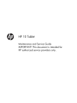
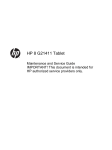
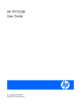
HP 2540 Docking Station
User Guide
© Copyright 2010 Hewlett-Packard
Development Company, L.P.
Microsoft is a U.S. registered trademark of
Microsoft Corporation.
The information contained herein is subject
to change without notice. The only
warranties for HP products and services are
set forth in the express warranty statements
accompanying such products and services.
Nothing herein should be construed as
constituting an additional warranty. HP shall
not be liable for technical or editorial errors
or omissions contained herein.
First Edition: March 2010
Document Part Number: 607792-001
Table of contents
1 Identifying components ................................................................................................................................. 1
Top components ................................................................................................................................... 1
Right-side components ......................................................................................................................... 2
Rear components ................................................................................................................................. 3
Getting more information ...................................................................................................................... 3
2 Docking and undocking ................................................................................................................................. 4
Connecting to the AC adapter .............................................................................................................. 4
Docking the computer .......................................................................................................................... 4
Undocking the computer ...................................................................................................................... 5
3 Using the docking station .............................................................................................................................. 7
Turning the computer on and off .......................................................................................................... 7
Connecting an optional security cable .................................................................................................. 7
4 Troubleshooting .............................................................................................................................................. 9
Docking and undocking problems and solutions .................................................................................. 9
External device problems and solutions ............................................................................................. 10
Appendix A Spare parts .................................................................................................................................. 11
Appendix B Connector pin assignments ....................................................................................................... 12
Audio-out (headphone) ....................................................................................................................... 12
Audio-in (microphone) ........................................................................................................................ 12
External monitor ................................................................................................................................. 13
RJ-11 (modem) .................................................................................................................................. 14
RJ-45 (network) .................................................................................................................................. 14
Universal Serial Bus ........................................................................................................................... 15
Appendix C Power cord set requirements .................................................................................................... 16
Requirements for all countries and regions ........................................................................................ 16
Requirements for specific countries and regions ............................................................................... 16
Index ................................................................................................................................................................... 18
iii
iv
1
Identifying components
Top components
Component
Description
(1)
Docking posts (2)
Align and secure the computer for proper connection to the
docking station.
(2)
Power button
Turns on power to the computer.
(3)
Computer power light
●
On: A docked computer is turned on.
●
Blinking: A docked computer is in the Sleep or Standby
state.
●
Off: A docked computer is off or in Hibernation.
(4)
Computer connect/release
mechanisms (2)
Connect and release the computer when you press the
connect button.
(5)
Docking connector
Connects the computer to the docking station.
(6)
Connect button
Secures and releases the computer.
(7)
Connect light
●
Slide in to secure the computer.
●
Slide out to release the computer.
On: A computer is fully docked.
Top components
1
Right-side components
(1)
Component
Description
Connect button
Secures and releases the computer
●
Slide in to secure the computer.
●
Slide out to release the computer.
(2)
Connect light
On: A computer is fully docked.
(3)
Computer power light
●
On: A docked computer is turned on.
●
Blinking: A docked computer is in the Sleep or Standby state.
●
Off: A docked computer is off or in Hibernation.
(4)
Powered USB 2.0 port
Provides power to an external device if used with a powered USB cable.
(5)
Vent
Enables airflow to cool internal components.
CAUTION: To prevent overheating, do not obstruct vents. Use the
computer and the docking station only on a hard, flat surface. Do not allow
another hard surface, such as an adjoining optional printer, or a soft
surface, such as pillows or thick rugs or clothing to block airflow.
(6)
HP Lock
Secures the docking station and a connected computer or only the
docking station with an optional security cable (purchased separately).
NOTE: A security cable is designed to act as a deterrent, but it may not
prevent the computer or the docking station from being mishandled or
stolen.
2
Chapter 1 Identifying components
Rear components
Component
Description
(1)
Integrated security cable slot (for
locking the docking station
only)
Supports an optional security cable, which secures the docking station
when a computer is not connected.
(2)
Integrated security cable slot (for
locking the computer and the
docking station)
Supports an optional security cable, which secures the docking station and
a connected computer.
(3)
RJ-45 (network) jack
Connects a network cable.
(4)
External monitor port
Connects an external VGA monitor.
(5)
Monitor stand port
Connects the docking station to an optional HP monitor stand.
(6)
eSATA port
Connects the docking station to high-performance eSATA components,
such as an eSATA external hard drive.
(7)
USB ports (3)
Connect USB devices.
(8)
DisplayPort
Connects the docking station to an option digital display device, such as
a high-performance monitor or projector.
(9)
Audio-in jack
Connects home audio equipment such as CD and MP3 players.
(10)
Audio-out jack
Produces computer sound when connected to optional powered stereo
speakers, headphones, ear buds, a headset, or television audio.
(11)
Power connector
Connects the docking station to the AC adapter.
(12)
Power light
On: The docking station is connected to AC power.
Getting more information
WARNING! To reduce the risk of serious injury, read the Safety and Comfort Guide. It describes proper
workstation setup, and proper posture, health, and work habits for notebook users. The Safety and
Comfort Guide also provides important electrical and mechanical safety information. This guide is
available on the Accessory User Guides disc and the Web at http://www.hp.com/ergo.
●
Help and Support on your computer includes information about the use of your computer. Click
Start > Help and Support.
●
Governmental agency and safety information about the use of this device is also included on the
Accessory User Guides disc.
●
The HP Web site at http://www.hp.com provides product news and software updates.
Rear components
3
2
Docking and undocking
Connecting to the AC adapter
The docking station requires AC power for full functionality of all ports.
WARNING! To reduce the risk of electric shock or damage to your equipment:
Plug the power cord into an AC outlet that is easily accessible at all times.
Disconnect the power from the product by unplugging the power cord from the AC outlet.
If provided with a 3-pin attachment plug on your power cord, plug the cord into a grounded (earthed) 3pin outlet. Do not disable the power cord grounding pin; for example, by attaching a 2-pin adapter. The
grounding pin is an important safety feature.
Do not place anything on power cords or cables. Arrange them so that no one can accidentally step on
or trip over them.
Do not pull on a cord or cable. When unplugging a cord from the AC outlet, grasp the cord by the plug.
WARNING! To reduce the risk of electric shock, fire, or damage to the equipment, do not attempt to
operate the computer and docking station with a voltage converter kit sold for appliances. Use only the
power cord included with the docking station.
To connect the docking station to AC power:
1.
Plug the AC adapter into the power connector (1) on the docking station.
2.
Plug the power cord into the AC adapter (2).
3.
Plug the other end of the power cord into an AC outlet (3).
Docking the computer
To dock the computer:
1.
4
Slide the connect button all the way to the right (1).
Chapter 2 Docking and undocking
2.
Align the docking posts on the docking station with the receptors on the bottom of the computer
and lower the computer into the docking station (2).
3.
Slide the connect button (1) to the left to fully dock the computer.
The connect light (2) will be turned on.
Undocking the computer
To undock the computer:
1.
Slide the connect button (1) to the right. The computer disconnects from the docking station.
Undocking the computer
5
2.
6
Lift up the computer (2).
Chapter 2 Docking and undocking
3
Using the docking station
Turning the computer on and off
When you connect a computer to the docking station, you can turn the computer on and off using either
the computer power button or the docking station power button.
When you turn on the computer using either button, the computer power light on the docking station is
turned on.
Connecting an optional security cable
NOTE: The security cable is designed to act as a deterrent, but it may not prevent the computer from
being mishandled or stolen.
The docking station has two security cable slots. One slot is used for a cable that can secure either the
docking station alone or the docking station and a docked computer. The other slot is used for a cable
that only secures the docking station.
To connect an optional security cable to secure only the docking station or the docking station and a
docked computer:
1.
Loop the security cable around a secured object.
2.
Insert the security cable connector (1) into the security cable port at the back of the docking station.
3.
Insert the key into the lock slot on the right side of the docking station (2).
Turning the computer on and off
7
4.
Turn the key to the 1 or 2 position (3) to secure the lock and security cable, and then remove the
key (4).
To connect an optional security cable to secure only the docking station:
8
1.
Loop the security cable around a secured object.
2.
Insert the cable lock into the security cable slot on the back of the docking station, and then lock
the cable lock.
Chapter 3 Using the docking station
4
Troubleshooting
If you experience problems with your docking station, follow the troubleshooting steps below:
1.
Refer to the information in this chapter.
2.
Access Help and Support by selecting Start > Help and Support from your computer. In addition
to providing information about your operating system, Help and Support provides a searchable
database of help topics, updated regularly by HP and Microsoft. Type in the name of your accessory
—for example, docking station—to search for relevant topics in the HP Knowledge Base and
Microsoft® Knowledge Base.
3.
Visit the HP Web site at http://www.hp.com. Then select your country or region.
Docking and undocking problems and solutions
Problem
Possible cause
Solution
The connect button on the docking
station will not slide to secure the
computer.
An optional security cable is connected
to the wrong security cable slot.
Disconnect the security cable.
The computer is turned on and properly
docked, but the power light is not on.
The power cord is not plugged into either
the docking station or the AC outlet.
Properly plug in the power cord.
The computer will not disconnect from
the docking station.
The connectors may be jammed.
Slide the connect button all the way in
and then slide it all the way out. If the
computer does not disconnect, repeat
this procedure.
CAUTION: Applying excessive force
may damage connector pins.
An optional security cable is connected.
Disconnect the security cable.
Docking and undocking problems and solutions
9
External device problems and solutions
10
Problem
Possible Cause
A new device is not recognized as part of
the system.
The computer may not be fully seated or Undock the computer and dock it again.
docked in the docking station.
Be sure the computer is properly seated
and fully docked.
Chapter 4 Troubleshooting
Solution
The device cable or power cord is loose. ●
Be sure that all cables are securely
connected to the device and the
docking station.
●
Be sure that all power cords are
securely plugged into the device or
docking station and into an AC
outlet.
The device was connected while the
system was on.
Turn off the computer, turn on the device
(if applicable), and then turn on the
computer.
Cabling is incorrect.
Be sure that the device cable is in the
correct connector on the docking station.
You may need to install device drivers on
the computer.
Install drivers according to the device
manufacturer's instructions.
A
Spare parts
Description
Part number
SPS-DOCKING STATION 2540 SERIES
598774-001
11
B
Connector pin assignments
Audio-out (headphone)
Pin
Signal
1
Audio out, left channel
2
Audio out, right channel
3
Ground
Audio-in (microphone)
12
Pin
Signal
1
Audio signal in
2
Audio signal in
3
Ground
Appendix B Connector pin assignments
External monitor
Pin
Signal
1
Red analog
2
Green analog
3
Blue analog
4
Not connected
5
Ground
6
Ground analog
7
Ground analog
8
Ground analog
9
+5 VDC
10
Ground
11
Monitor detect
12
DDC 2B data
13
Horizontal sync
14
Vertical sync
15
DDC 2B clock
External monitor
13
RJ-11 (modem)
Pin
Signal
1
Unused
2
Tip
3
Ring
4
Unused
5
Unused
6
Unused
RJ-45 (network)
14
Pin
Signal
1
Transmit +
2
Transmit -
3
Receive +
4
Unused
5
Unused
6
Receive -
7
Unused
8
Unused
Appendix B Connector pin assignments
Universal Serial Bus
Pin
Signal
1
+5 VDC
2
Data -
3
Data +
4
Ground
Universal Serial Bus
15
C
Power cord set requirements
The wide range input feature of the docking station permits it to operate from any line voltage from 100
to 120 volts AC or from 220 to 240 volts AC.
The 3-conductor power cord set included with the docking station meets the requirements for use in the
country or region where the equipment is purchased.
Power cord sets for use in other countries and regions must meet the requirements of the country or
region where the docking station is used.
Requirements for all countries and regions
The requirements listed below are applicable to all countries and regions:
●
The length of the power cord set must be at least 1.5 m (5.0 ft) and no more than 2.0 m (6.5 ft).
●
All power cord sets must be approved by an acceptable accredited agency responsible for
evaluation in the country or region where the power cord set will be used.
●
The power cord sets must have a minimum current capacity of 10 amps and a nominal voltage
rating of 125 or 250 V AC, as required by the power system of each country or region.
●
The appliance coupler must meet the mechanical configuration of an EN 60 320/IEC 320 Standard
Sheet C13 connector for mating with the appliance inlet on the back of the docking station.
Requirements for specific countries and regions
16
Country/region
Accredited agency
Applicable note number
Australia
EANSW
1
Austria
OVE
1
Belgium
CEBC
1
Canada
CSA
2
Denmark
DEMKO
1
Finland
FIMKO
1
France
UTE
1
Germany
VDE
1
Italy
IMQ
1
Japan
METI
3
Korea
EK
4
The Netherlands
KEMA
1
Norway
NEMKO
1
The People's Republic of China
CCC
5
Appendix C Power cord set requirements
Country/region
Accredited agency
Applicable note number
Sweden
SEMKO
1
Switzerland
SEV
1
Taiwan
BSMI
4
The United Kingdom
BSI
1
The United States
UL
2
1.
The flexible cord must be Type HO5VV-F, 3-conductor, 1.0-mm² conductor size. Power cord set fittings (appliance coupler
and wall plug) must bear the certification mark of the agency responsible for evaluation in the country or region where it
will be used.
2.
The flexible cord must be Type SPT-3 or equivalent, No. 18 AWG, 3-conductor. The wall plug must be a two-pole grounding
type with a NEMA 5-15P (15 A, 125 V) or NEMA 6-15P (15 A, 250 V) configuration.
3.
The appliance coupler, flexible cord, and wall plug must bear a “T” mark and registration number in accordance with the
Japanese Dentori Law. The flexible cord must be Type VCT or VCTF, 3-conductor, 1.00-mm² conductor size. The wall
plug must be a two-pole grounding type with a Japanese Industrial Standard C8303 (7 A, 125 V) configuration.
4.
The flexible cord must be Type RVV, 3-conductor, 0.75-mm² conductor size. Power cord set fittings (appliance coupler
and wall plug) must bear the certification mark of the agency responsible for evaluation in the country or region where it
will be used.
5.
The flexible cord must be Type VCTF, 3-conductor, 0.75-mm² conductor size. Power cord set fittings (appliance coupler
and wall plug) must bear the certification mark of the agency responsible for evaluation in the country or region where it
will be used.
Requirements for specific countries and regions
17
Index
A
AC adapter, connecting 4
additional information 3
audio-in jack
pin assignments 12
audio-out jack
pin assignments 12
B
buttons
connect 1, 2, 5
power 1, 7
C
computer
docking 4
turning off and on 7
undocking 5
computer power light 1, 2
connect button 1, 2, 5
connect light 1, 2, 5
connectors
docking 1
power 3
D
device not recognized 10
docking connector 1
docking posts 1
docking problems 9
docking the computer 4
E
external devices,
troubleshooting 10
external monitor port
pin assignments 13
H
headphone jack
pin assignments 12
help 3
18
Index
J
jacks
audio-in 3
audio-out 3
RJ-45 (network) 3
L
lights
computer power 1, 2
connect 1, 2, 5
power 3
M
microphone jack
pin assignments
modem jack
pin assignments
monitor port
pin assignments
monitor stand port
12
power connector 3
power cord
set requirements 16
power light 3
power light, computer 1, 2
power, connecting 4
powered USB port 2
R
rear components 3
right-side components 2
RJ-11 jack
pin assignments 14
RJ-45 (network) jack 3
RJ-45 jack
pin assignments 14
14
13
3
N
network jack
pin assignments 14
P
pin assignments
audio-in jack 12
audio-out jack 12
external monitor port 13
headphone jack 12
microphone jack 12
modem jack 14
monitor port 13
network jack 14
RJ-11 14
RJ-45 jack 14
Universal Serial Bus (USB)
port 15
ports
external monitor 3
monitor stand 3
USB 2, 3
power button 1, 7
S
safety information 3
security cable slots 3, 7
security cable, connecting 7
slots, security cable 3, 7
spare parts 11
T
top components 1
troubleshooting 9
turning off and on the computer 7
U
undocking problems 9
undocking the computer 5
Universal Serial Bus (USB) port
pin assignments 15
USB port 2, 3
V
vent 2