1
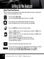
Quick Start Guide
Combustion Gas Analyzer
This quick guide provides basic setup, operating and maintenance
information for the Fyrite® INSIGHT. If required, more detailed
information concerning the analyzer’s technical specifications,
operation, set-up, calibration, and parts list can be downloaded from
MyBacharach.com/insight (P/N 24-9460) .
M y B a c h a r a c h . c o m • F y r i t e ® I n S i g h t • I n s t r u c t i o n 24 - 9 4 6 0
2
Setting Up the Analyzer
Front Panel Push Buttons
Note that a push button may perform several functions, depending on the analyzer’s model number
and what screen is being displayed at the time.
•Turns the analyzer ON and OFF.
•Turns the backlight ON and OFF while the analyzer is turned ON.
•Scrolls up, down, left, and right through the display screen options.
•Causes the displayed value to increase or decrease correspondingly.
•Acts as an ENTER button. Performs the action selected.
• While in the HOLD screen, turns the sample pump on, displays the RUN screen,
and begins a combustion test.
• While in the RUN screen, turns the sample pump off, displays the HOLD screen
and the last set of combustion data.
• Displays the HOLD screen while pressing it from most menus.
• Return the display to the HOLD screen while pressing it during the 5 second power down sequence.
• Cancels most operations and displays the previous screen.
•Pressing function keys accepts the corresponding function defined at the bottom
of the display including PRINT, SAVE, MENU, differential pressure ZERO, differential temperature ZERO, PAGE UP, PAGE DOWN, and CLEAR data.
3
I n s t r u c t i o n 24 - 9 4 6 0 • F y r i t e ® I n S i g h t • M y B a c h a r a c h . c o m
Operating Tips
1. When an analyzer is brought in from a cold vehicle, let it warm up slowly to minimize
condensation. Temperatures below freezing will not damage the analyzer; however, bringing
a cold analyzer into a warm, humid environment may cause condensate to form inside the
case.
Caution: Although the analyzer itself is not damaged by an extremely cold environment,
the electrochemical sensors may be damaged. The O2 sensor’s electrolyte will freeze
at approximately -20 °F and the CO sensors at approximately -94 °F. If the analyzer is
exposed to an extremely cold condition, it is strongly suggested that the sensor housings
be examined for hairline cracks. Be aware that a leaking sensor can cause chemical
burns to the skin and possibly damage the PCB assemblies.
2. Ensure that the analyzer is sampling fresh air when turned ON. Pulling a stack-gas sample
through the analyzer during its warm-up period will not damage the analyzer, but it will result
in incorrect sensor readings, and may result in sensor error messages appearing after the
warm-up cycle completes.
Note that flue-gas condensate is acidic and very corrosive. It is important not to allow the
analyzer’s internal components to come in contact with condensate for long periods of time.
3. Before each use, inspect the filter element of the water-trap / filter assembly. Replace the filter
if it looks dirty.
4. When sampling flue-gas, keep the analyzer above the water-trap, and keep the trap in a vertical
position. This will maximize the effectiveness of the trap and keep liquid from being drawn
directly into the analyzer.
5. When liquid condensate is seen inside the water trap, empty the trap before it becomes full.
6. When storing the analyzer, it’s a good idea to empty the water trap and leave it open to further
dry it out.
7. Calibrate the analyzer every 6 months - 1 year to assure its accuracy
M y B a c h a r a c h . c o m • F y r i t e ® I n S i g h t • I n s t r u c t i o n 24 - 9 4 6 0
4
Performing Tests
Make sure that the sample point is before any draft diverter/hood or barometric damper so that the
flue gasses are not diluted and the stack temperature has not been decreased by surrounding air
used to balance the draft.
The sample point should also be as close to the breach area as possible, again, to obtain an accurate
stack temperature. This will also provide a more accurate O 2 reading should air be entering the flue
gas stream through joints in sheet metal vent connectors.
When testing atmospheric, forced air heating equipment with a clamshell or sectional heat exchanger
design, test each of the exhaust ports at the top of the heat exchanger. The probe should be inserted
back into each of the exhaust ports to obtain a flue gas sample, before any dilution air is mixed in.
Draft tests should be taken from a hole drilled in the stack downstream from the draft hood.
Combustion and draft testing fan assist, furnaces/boilers should be
done through a hole drilled in the vent immediately above the inducer
fan. While fan assist equipment operates under a negative draft, it
is good practice to seal the sample hole, high temperature silicone is
generally recommended.
5
I n s t r u c t i o n 24 - 9 4 6 0 • F y r i t e ® I n S i g h t • M y B a c h a r a c h . c o m
Performing Tests
Boilers, which have a ‘bell’ shaped draft diverter directly on top,
should be tested directly below the diverter through a hole-drilled
in the vent connector.
Should draft tests below the diverter measure insufficient draft
levels, an additional test should be performed above the diverter to
determine if the reason for insufficient draft is related to a chimney
problem or a draft hood problem.
It is also a good idea to test any areas with openings that provide a
path for combustion air to be introduced to the flame. These areas
provide a path where flue gases can potentially be exhausted.
With forced air systems this area is generally limited to
immediately in front of the burners while many styles of
boilers allow secondary combustion air to also be drawn
in from all around the base of the cabinet.
Gas and oil fired power burners should be tested up
stream from the barometric, as close to the breech area
as possible.
While stack draft may be an important measurement,
fuel oil and gas fired power burners require draft control
over the fire to maintain a proper and controlled intake
of combustion air.
M y B a c h a r a c h . c o m • F y r i t e ® I n S i g h t • I n s t r u c t i o n 24 - 9 4 6 0
6
Performing Tests
Diagnostics Menu
1. In the MAIN MENU highlight the DIAGNOSTICS MENU and select ENTER. This screen
allows you to look at the total run times for the instrument, check O 2 and CO sensor status
and thermocouple output.
Turning Off the Analyzer
1. Before turning off the instrument, disconnect the hose and probe assembly and check the
water trap for moisture, empty if necessary. Allow the instrument to continue to pump
fresh air for a few minutes to make sure all water and flue gases are purged from the internal
components.
2. Press and hold down the POWER button for approximately 2 seconds at which time the display
will read PURGING SENSORS, then count down for 5 seconds and power off.
3. You can also opt to set the instrument up to do a longer post purge period by going to the
MAIN MENU, SETUP and scrolling down to the POST-PURGE PERIOD and pressing the
ENTER button. The default time from the factory is 5 seconds; you can also select NONE
(We recommend against no purge), 1 minute, 5 minutes or 10 minutes.
Calibration and Maintenance: IMPORTANT
1. Before performing any calibration procedure, ensure that fresh batteries are installed or use
the optional AC power adapter. Also, ensure that the analyzer is at room temperature and
will be sampling fresh air when turned ON.
7
IMPORTANT: To maintain accuracy, the standards used must be at least four times as
accurate as the stated accuracy of the Fyrite® INSIGHT. (See INSIGHT instruction manual
P/N 24-9460)
I n s t r u c t i o n 24 - 9 4 6 0 • F y r i t e ® I n S i g h t • M y B a c h a r a c h . c o m
B-Smart Sensors
™
The Fyrite® INSIGHT utilizes Bacharach’s new Smart Sensor technology for its CO sensors.
B-Smart™ sensors are market with a 10-Digit Calibration Code that can be entered in the
B-Smart™ calibration screen. Once the B-Smart™ code is entered and the sensor is installed
the CO channel is calibrated.
Benefits of Smart Sensors:
a.
b.
c.
d.
New sensors can be installed without needing to be calibrated.
Sensors can be pre-calibrated and installed when needed.
Sensors can be moved from one analyzer to another.
Sensors can be sent in for calibration without sending in the entire instrument.
The smart sensors should be calibrated every
6 months to 1 year to assure that the analyzer
continues to meet its published accuracy
specifications. For details surrounding the
B-Smart™ re-calibration program, go to
MyBacharach.com\bsmart. For additional
information regarding Calibration, see
specification model located at MyBacharach.
com\insight.
M y B a c h a r a c h . c o m • F y r i t e ® I n S i g h t • I n s t r u c t i o n 24 - 9 4 6 0
8
Setting Up the Analyzer
Preliminary Steps
Before using the analyzer . . .
• Check batteries
• Connect probe to analyzer
• Check setup
Analyzer Turn On and Warm up
1. Remove the back cover and install the 4 AA batteries.
2. Connect the probe and hose assembly. Note the combustion hose fitting is slightly larger
in diameter than the pressure hose fitting. The stack thermocouple plugs into the yellow
connector on the left hand side with the wider prong on the right.
3. Turn ON the analyzer by pressing the PWR button for a second until the pump starts up and
the display comes on. For several seconds you will see the Version, Model Number and Serial
Number of the instrument displayed, the instrument will then start a 60 second countdown to
allow the sensors to calibrate. NOTE: make sure the probe is sampling fresh air during these
60 seconds. To set the time/date and other settings go to the SETUP section.
4. The first screen that comes up is in the HOLD position. To start sampling press the RUN/
HOLD button. The backlight will be illuminated at start-up.
Fuel Type
1. The FUEL TYPE will be displayed at the top of the screen. To change to another fuel, press the
MENU (F2) button, the MAIN MENU will be displayed with the FUEL selection highlighted.
Press the round, green, ENTER button in the center of the keypad to select FUEL, scroll the up/
down keypad until the cursor is highlighting the desired fuel and press the ENTER button. That
will return you to the HOLD screen; press the RUN/HOLD button to continue operation.
9
I n s t r u c t i o n 24 - 9 4 6 0 • F y r i t e ® I n S i g h t • M y B a c h a r a c h . c o m
Setting Up the Analyzer
Setup
1. The analyzer is preset at the factory for the parameters shown below, but can be changed as
described in their associated sections. The functions include:
Fuel (8 options)
Temperature Unit (Fahrenheit/Celsius)
Pressure Units (Inches of water column, Pascals, etc.)
Clock
O 2 REFERENCE (calculates the CO reference to O 2 reading)
Print Pressure (measurement on combustion printout)
Zoom (2-4 lines of text in the screen)
Username (company name, address, phone #)
Run/Hold Format*
Language Selection (English, French, Spanish)
Button Sound
Calibration Reminder Period (6, 8, 10, 12 or 15 month reminders)
Inactivity Timeout (30 or 60 minutes – set to None)
Post-Purge Period (5 seconds, 1,5 or 10 minutes)
Date Format
2. To enter Setup; in the MAIN MENU screen, highlight SETUP and press ENTER.
3. Highlight the function you want to change by scrolling up and down. Make selections by
hitting the ENTER button. From there, additional scrolling either up and down or side to side
is required.
4. *RUN/HOLD FORMAT determines what order the combustion readings are displayed. Press
the ENTER button and select EDIT FORMAT. To change the order in which the data is displayed,
scroll up or down to select the position you want to change and press the ENTER button.
The cursor should start flashing. Press the up or down keys to scroll through and select the
desired data to appear in that location and press ENTER. Change the data at other locations
by scrolling up or down and repeating the procedure. To go back to the default setting, select
RESET FORMAT.
M y B a c h a r a c h . c o m • F y r i t e ® I n S i g h t • I n s t r u c t i o n 24 - 9 4 6 0
10
Performing Tests
Performing a Combustion Test Using the Fyrite® INSIGHT
After the analyzer is powered up and the appropriate
fuel selected, insert the probe in the proper sample
location for the equipment being tested. Contact
the manufacturer of specific equipment or consult
the manufacturers’ literature to determine the
proper sample locations for combustion/carbon
monoxide, stack temperature and draft tests. The
following are recognized as generally accepted
locations for testing heating equipment, consult
with the manufacturer of specific equipment to
make certain.
The measurement for gases and temperature
should be taken at the same point. Typically, this
is done by selecting a sample location ‘upstream’
from the draft diverter/hood, barometric control
or any other opening, which allows room air
to enter and dilute flue gases in the stack. In
larger installations it may also be necessary to
extract a number of samples from inside the
flue to determine the area of greatest flue gas
concentration. Another common practice is to
take the flue gas sample from the ‘Hot Spot’ or the
area with the highest temperature.
11
draft
O2, CO air
free and stack
temperature
Atmospheric furnace
I n s t r u c t i o n 24 - 9 4 6 0 • F y r i t e ® I n S i g h t • M y B a c h a r a c h . c o m
Performing Tests
Condensing furnaces/boilers can be tested through a
hole drilled in the plastic vent pipe (when allowed by the
manufacturer or ‘local authority of jurisdiction) or taken from
the exhaust termination.
In order to obtain an accurate Steady State Efficiency reading,
an auxiliary thermocouple must be inserted in the combustion
air intake so that a true net stack temperature is used in the
calculation.
It is important to remember that the vent system on these units
operates under a positive pressure. As a result, any holes in
the vent need to be sealed.
Domestic hot water heaters with the ‘bell’ shaped draft
diverter on top can be accurately tested by attaching a
section of copper tubing to the probe or using a flexible
probe which is then inserted directly into the top of the
fire tube below the diverter.
Another common practice is to insert the probe in the hole
drilled for the draft test, direct it down and push it below
the level of the draft hood.
M y B a c h a r a c h . c o m • F y r i t e ® I n S i g h t • I n s t r u c t i o n 24 - 9 4 6 0
12
Performing Tests
Pressure
1. To measure draft, gas pressure, External Static Pressure, differential pressure, troubleshoot
pressure sensors, etc, press the F2 button to go to the MAIN MENU. Press the scroll down
button once to Highlight PRESSURE and press the center, green, ENTER button. Press the
F2 button to ZERO the pressure channel and follow the prompts in the screen.
2 Press the ESC button at any time to return to the previous screen.
Temperature (Differential)
1. Select the TEMPERATURE feature in the main menu to record/document temperature
differences (ie temperature rise). Two ‘K’ type thermocouples must be plugged into the bottom
of the instrument to use this feature. Press the F2 button to zero the temperature channels.
a. Note: Thermocouple should be located in same area to zero.
Saving test results
1. To save test results, simply press the F3 Key. To access the saved test results, go to the MAIN
MENU, scroll down to MEMORY and press the green ENTER button. Press the MEMORY
DIRECTORY and up to 100 sets of test results will load up. Scroll down to find the time/dated
set of test results and press the ENTER button to recall that information.
Documenting Test Results
1. To print a set of test results, point the IR transmitter located in the top of the INSIGHT, and
press the F1 or PRINT KEY. Flue gas test results or diagnostic information in the screen will
be printed.
2. To download the test results to the Bacharach Software through the supplied USB cable,
follow the instructions included with that package.
13
I n s t r u c t i o n 24 - 9 4 6 0 • F y r i t e ® I n S i g h t • M y B a c h a r a c h . c o m
Connecting the INSIGHT
Computer to InSight Connection & USB Device Driver Configuration
Connect the USB cable (P/N 104-4032) that was supplied with the InSight, and, if necessary,
install the analyzer’s USB device driver as follows:
1.With both the Insight and computer turned ON, insert the
appropriate ends of the USB cable into the USB connectors
on the Insight and computer as seen below.
2. If this is the first time the Insight is being connected to the
computer, then the “Found New Hardware Wizard” should
shortly appear. Select “No, not this time” and click NEXT.
(Note: The USB device driver only needs to be installed
once. It does not require to be re-installed each time
the Insight is connected to the the computer.)
3. Select “Install from a list or specific location (Advanced)”
and click NEXT.
4. Select to search for the best driver and then browse to folder
C:\Program Files\InSightData. Click NEXT.
5. At the Hardware Installation window, click CONTINUE
ANY WAY. Our driver has been thoroughly tested in
Windows for stability. This message appears because
Microsoft has not tested this product through WHQL
certification.
6. After the Found New Hardware Wizard has finished
installing the software, click FINISH to close the Wizard.
* Only available with the Reporting Kit
M y B a c h a r a c h . c o m • F y r i t e ® I n S i g h t • I n s t r u c t i o n 24 - 9 4 6 0
14
Potential Error Messages
1. O2 SENSOR MISSING - The O 2 sensor is not installed.
2. T-STK DISCONNECTED - The probe thermocouple is not connected to the analyzer’s T-Stack
connector. Plug the probe thermocouple plug into the T-Stack connector at the bottom of the
instrument.
3. BAD SENSOR - O 2 sensor is too low and can not be calibrated in the instrument and needs
replaced.
4. LOW SENSORS - O 2 or CO sensor outputs were low but still usable. Sensor(s) may need to be
replaced in the near future. Message will indicate which sensor(s) were in warning.
5. WARMUP SENSOR ERROR - CO sensor was not zeroed at warm-up because of high output.
Run instrument on fresh air then restart instrument to re-zero sensor. If message persists CO
sensor may need to be replaced.
a. Stack or Air temperature channel is measuring temperature outside the range of -4 to 212˚F
at startup. Make sure that the Stack and Air thermocouples are sampling ambient room
air within the temperature range at startup.
b. Pressure sensor is measuring pressure outside the range of ± 3 in wc at startup. Ensure
that the analyzer is sampling atmospheric pressure and restart the instrument.
c. The analyzer was turned on with the probe sampling flue gas. Move the probe to fresh air
and restart the instrument.
d. Message will indicate which channel is in error.
6. LOW BATTERY - Battery voltage is low. Replace the batteries.
7. XXXX - Occurs in the number fields of sensors that are in over-range.
8. **** Occurs in the number fields of sensors and the calculated values that depend on the
sensors that were in error coming out or warm-up.
9. **** Occurs in the number fields of calculated values when Oxygen is above 16%.
15
I n s t r u c t i o n 24 - 9 4 6 0 • F y r i t e ® I n S i g h t • M y B a c h a r a c h . c o m
Parts and Service
Replacement Parts:
Accessories:
Description
Part No.
O 2 Sensor.............................................. 24-0788
CO Sensor..............................................24-7265
B-Smart™ CO Sensor...........................24-1467
O 2 Sensor Cover.................................... 24-1421
CO Sensor Cover...................................24-1484
Probe and Hose Assembly................... 24-3004
Water Trap ...........................................19-3265
Filter (pkg of 3)...................................... 07-1644
Thermocouple Replacement (12 in.).....24-8414
Probe Stop.............................................19-3037
Gas Connector...................................... 24-0877
Draft Connector................................... 24-0878
Connector Plate Assembly...................24-1483
O-Ring Kit (2 sets)................................. 24-1471
USB cable........................................... 104-4032
Carry Case............................................ 24-0865
Replacement Pump.............................. 24-3049
PC Software.......................................... 24-1470
Battery / Sensor Cover.........................24-1453
Description
Part No.
IrDA Printer .................................... 24-1400
Printer Paper (pkg. of 5)...................24-1310
Printer Paper (pkg. of 1)..................06-8733
Boot................................................. 24-1461
AC Adapter . ................................... 24-1254
Calibration Kit ................................ 24-7059
Calibration Gas, 500 ppm CO..........24-0492
Calibration Gas, 100 ppm CO...........51-1994
Thermocouple, 1 IN....................... 104-1798
Thermocouple, 10 FT.................... 104-1797
Smoke Kit ....................................... 21-7006
Pressure Kit . .................................. 24-8214
M y B a c h a r a c h . c o m • F y r i t e ® I n S i g h t • I n s t r u c t i o n 24 - 9 4 6 0
16
Service Centers
Replacement parts and service can be obtained by contacting
one of the following Bacharach Service Centers:
United States
Headquarters
621 Hunt Valley Circle
New Kensington, Pennsylvania 15068
Phone: 724-334-5051
Fax: 724-334-5723
Email: [email protected]
Canada
Bacharach of Canada, Inc.
250 Shields Court Unit #3
Markham, Ontario L3R 9W7 Canada
Phone: 905-470-8985
Fax: 905-470-8963
Email: [email protected]
México
Bacharach de México
Playa Regatas No. 473 Tercer Piso
Col. Militar Marte
Delegación Iztacalco, 08830
México D.F. México
Phones: +52-555-634-7740
+52-555-634-7741
Fax: +52-555-634-7738
Email: [email protected]
17
I n s t r u c t i o n 24 - 9 4 6 0 • F y r i t e ® I n S i g h t • M y B a c h a r a c h . c o m
lusi
E xc
v el y f r o m
Headquarters: 621 Hunt Valley Circle
New Kensington, Pennsylvania 15068-7074 U.S.A.
Phone: 1-800-736-4666 • www.MyBacharach.com
BAC1-5461 - Rev.0