1
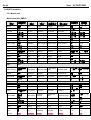
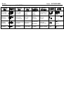
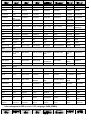
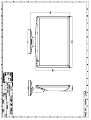
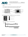
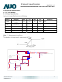
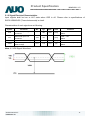
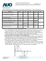
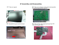
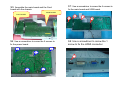
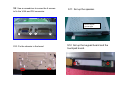
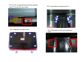
Acer Acer –LCD-D240H Service Manual LCD Monitor Acer D240H 1 Table of Contents Important Safety Notice .........................................................................................02 01 Product Specification ..........................................................................................03 02 Flat Panel Specification .......................................................................................15 03 Exploded Diagram ..............................................................................................36 04 Troubleshooting ....................................................................................................37 05 Spare Parts List ...................................................................................................42 06 Schematics and Layouts.......................................................................................43 07 Assembly and Disassembly ................................................................................46 Appendix : User’s manual Copyright Copyright 2006 InnoLux Tech. Corp. Ltd All Rights Reserved This manual may not, in whole or in part, be copied, Photocopied, reproduced, translated, or converted to any electronic or machine readable form without prior written permission of InnoLux Tech. Corp. Ltd. Acer D240H Service Manual 1 Acer Acer –LCD-D240H Important Safety Notice 1. Safety precautions This monitor is manufactured and tested on a ground principle that a user’s safety comes first. However, improper used or installation may cause damage to the monitor as well as to the user. Warning: This monitor should be operated only at the correct power sources indicated on the label on the rear of the monitor. If you’re unsure of the power supply in you residence, consult your local dealer or Power Company. Do not try to repair the monitor by yourself, as it contains no user-serviceable parts. This monitor should only be repaired by a qualified technician. Do not remove the monitor cabinet. There are high-voltage parts inside that may cause electric shock to human bodies. Stop using the monitor if the cabinet is damaged. Have it checked by a service technician. Put your monitor only in a lean, cool, dry environment. If it gets wet, unplug the power cable immediately and consult your closed dealer. Always unplug the monitor before cleaning it. Clean the cabinet with a clean, dry cloth. Apply non-ammonia based cleaner onto the cloth, not directly onto the class screen. Do not place heavy objects on the monitor or power cord. z z z z z z z 2. Product safety notice Many electrical and mechanical parts in this chassis have special safety visual inspections and the protection afforded by them cannot necessarily be obtained by using replacement components rated for higher voltage, wattage, etc. Before replacing any of these components read the parts list in this manual carefully. The use of substitute replacement parts, which do not have the same safety characteristics as specified in the parts list, may create shock, fire, or other hazards. 3. Service notes z When replacing parts or circuit boards, clamp the lead wires around terminals before soldering. z Keep wires away from high voltage, high temperature components and sharp edges. z Keep wires in their original position so as to reduce interference. z Adjustment of this product please refers to the user’ manual. Acer Acer –LCD-D240H 01 Product Specification 1. General: Acer D240H is designed with LVDS interface and VGA/DVI-D/HDMI input, and Embedded DPF Function ,it featured with embedded universal AC power supplies and audio input. It’s a green product and meets all ROHS standard. The power button and display control buttons are on the front of the monitor. The monitors shall automatically to display lower resolution video modes into 1920x1080 full screen display. It can support 720P when DPF Mode,The image can be adjusted through OSD control. It support HDCP and color management function. 1.1 Main Features Maximum resolution : 1920(x3) x 1080 @ 60Hz Back light system : 4 CCFL (top & bottom edge side) Pixel pitch : 276.75 um (H) x 276.75 um (V) Display area : 531.36mm (H) x 298.89mm (V) Brightness : 300cd/m² (TYP.) Contrast ratio : 1000׃1 (TYP.) DCR :80000:1 (Max) Response time (Tr+Tf) : 5ms (TYP. ON/OFF) 2ms (Gray to Gray) Viewing angle : 170° (H)/ 160°(V), (TYP.) Input interface : Analog (D-sub 15 pin) Digital Option (DVI-D 24 pin & HDMI 19Pin) Power management : Compatible with VESA DPMS Plug & Play : VESA DDCCI OSD language : English, French, Spanish, Italian, Deutsch, Simplified Chinese, Traditional Chinese, Japanese (Dutch, Finnish, Russian depend on sale region) Universal AC power supply 1.2 Accessories AC Power Cord : 1.8 m. (Black. Cord type depend on sale region) VGA cable : 1.8 m. (15 pin D-SUB, black cable with blue male connector) User manual : English (640Mb CD) Warranty card : DVI cable (option) : 1.8 m. (18+1 pin, black cable with white connector) HDMI cable (option) : 1.8 m. (19 pin, black cable with white connector) Acer Acer –LCD-D240H USB: USB2.0 (optional function) Webcam: 1.0M resolution(1280 x 800), standard USB2.0 interface, array microphone (optional function) 2. Operation Specifications The unit should suffer no visible cosmetic damage and should operate with no degradation in display quality during exposure to the operating conditions and after exposure to the non-operating conditions, in any sequence. 2.1 Environmental conditions Operating Temperature range Relative humidity Altitude Storage Temperature range Relative humidity Altitude Specification 0°C to 50°C 5% to 90% 0 to 3048M (10000 ft) -20°C to 60°C 5% to 90% (not condense) 0 to 9144M (30000 ft) 2.2 Safety, EMC, Ergonomics and Compatibility Requirements Items Safety EMC Ergonomics Compatibility Power Management Description UL/c CB ● ● FCC CE ● ● TCO TCO03 ● ● Windows ● Energy Star ● TUV/G ● CCC ● CCC ● VCCI-B ● Windows 2000 ● 2.3 Electrostatic Discharge Requirements Other Windows ● Windows ● Acer Acer –LCD-D240H Item Electrostatic Discharge Condition Spec Contact discharge: 4KV IEC61000-4-2(EN55024) Contact discharge: 8KV Air discharge : 8KV Air discharge : 15KV ● ● Reliability Items Condition Spec MTBF T=25℃ >50,000 Hours, CCFL Life time Luminance becomes 50% Note 50,000 Hours(Typ) Note1 Note1. Display an all WHITE field at mid Brightness and Contrast settings. 3. Electrical and Optical Characteristics and Performance 3.1 Main Power Supply 3.1.1 Input characteristics Items Condition Spec AC Input Voltage range Universal input full range 90~264Vac AC Input Voltage rating Universal input full range 100~240Vac AC input frequency range 90~264Vac 47~63Hz AC input frequency rating 100~240Vac 50~60Hz AC Input Current 100Vac 2.0A(max) 240Vac 0.8A(max) 115Vac,cold star,25°C 35A (max) 230Vac,cold star,25°C 70A(max) DC output full loading ≥79% Inrush Current AC-DC power Efficiency Note See Note2 Note2. Before each test, the buck capacitor need to be discharged. Before each test, it must be 10 minutes at least after the latest test. Hot star not component be damaged. 3.1.2 Output characteristics Items Condition Spec Note Ripple and Noise DC Output Voltage +25V output +5V output USB +5V output: Audio +5V output: <800mv <500mv <150mv <500mv With system See note 3 +25V output <480mv With dummy Load +5V output USB +5V output: Audio +5V output: <100mv <100mv <100mv 25V loading:0.3A~1.4A 5V loading:0.75A~1.5A Audio 5V: 0A~1.2A USB 5V: 0A~1.5A Vcc25V:23.2V~28V Vcc5V: 4.75V~5.25V Audio 5V: 4.95V~5.45V USB 5V: 4.75V~5.25V 25v loading:0.1A~1.5A 5V loading: 0A Vcc25V: 23.2V~30V Vcc5V: 4.75V~5.25V For system active For power saving or DC off Acer Acer –LCD-D240H DC output loading capability Vcc5V/1.8A, Vcc25V/1.4A Audio 5V: 1.5A USB 5V: 1.5A <50mS Rise Time Dynamic load change Hold-up time AC input: 100V~240V >10mS Overshoot <10% Turn on delay time 2S Power management See Table-1 Note3: Paralleled a 0.1uF ceramic Cap. And 47uF aluminum Cap. Between the end of DC loading side, Measured band-width=20MHz. Ripple voltage of +25V is less than 1500mv when enter into burst mode. 3.1.3 Protection characteristics Protection Condition OPP(Over current protection) nominal AC input SCP(short circuit protection) with auto-recovery function OVP(Over voltage protection) Auto recovery OTP(Over temperature protection) NA Fuse protection NA Table-1 Status H-sync Power On Power Saving Power Off Spec 90W ( min ) <output capacitor voltage V-sync Video Power LED on on active ≤ 70W White off on blanked < 2W Amber on off blanked < 2W Amber off off blanked < 2W Amber -- -- -- < 1W Off 3.2 Backlight Power Supply Panel: AUO-M240HW01-V2 Items Specification Lamp 4 CCFL Input Voltage 23.2---28V Input current 1.2A (Typ.), 1.4A (Max.) On/Off switch level On/Off switch level 3.6V≧V on≧ 2.0 V (on) -0.3v ≤ V off ≤ 0.8 V (off) 3.6V≧V on≧ 2.0 V (on) -0.3v ≤ V off ≤ 0.8 V (off) Brightness PWM Duty (ACM Off) 35%~100% Brightness PWM Duty (ACM On) 3%~100% CCFL operating Voltage 900Vrms (Typ.), CCFL Current 7.5mA (Typ.) 8.0mA (Max.) Acer Acer –LCD-D240H CCFL startup voltage ≧2000 Vrms (0˚C) CCFL startup voltage ≧1850 Vrms (25˚C) Operating frequency 40~60 KHz Protect delay time > 1 second Efficiency ≥75% Note: Other panels please refer to the reference panel specs. Brightness output The test to verify specifications in this section shall be performed under the following standard conditions unless otherwise noted. Temperature : 25 ± 5°C Test pattern : white Video Resolution : 1920 x 1080 Video input level : 700 mV ± 2% Warm-up time : 30 minutes Set brightness control and also contrast control at maximum, to measure the screen center, the light output shall BL ≥ 240 cd/m2 . 3.3 White balance The test standard conditions refer to Sec 3.3. (Brightness and contrast are under default value) Mode Cool Warm User 9300K 6500K Chromaticity Coordinate x y 0.283 ± 0.030 0.297 ± 0.030 0.313 ± 0.030 0.329 ± 0.030 Panel While x Panel While y 3.4 Brightness uniformity The test standard conditions refer to Sec 3.3. Acer Acer –LCD-D240H Min. luminance of nine points (backlight) ≥75% Max. luminance of nine points (backlight) 4. Input / Output Signal Specifications 4.1 AC in 4.1.1 AC Input Voltage: 100~240VAC 4.1.2 AC Input Current: 1.2A @100Vac, 0.6A @240Vac 4.1.3 AC Frequency Range: 50~60Hz 4.2 Audio in 4.2.1 Input impedance ﹕ ≧ 10K ohm 4.2.2 Frequency response range ﹕200Hz ~ 10kHz 4.3 USB in (Option) The USB 2.0 includes 4 pins; pin1:VBUS; pin2:DM; pin3:DP; pin4:GND 4.4 HDMI in HDMI type A Connector Pin assignment: 19 18 Pin 1 2 3 4 5 6 7 8 9 10 17 16 15 14 13 Symbol TMDS Data2+ TMDS Data2 shield TMDS Data2TMDS Data1+ TMDS Data1 shield TMDS Data1TMDS Data0+ TMDS Data0 shield TMDS Data0TMDS Clock+ 12 11 10 9 Pin 11 12 13 14 15 16 17 18 19 8 7 6 5 4 3 Symbol TMDS Clock shield TMDS ClockCEC No connect SCL SDA DDC/CEC Ground +5V Power Hot Plug Detect 2 1 Acer Acer –LCD-D240H 4.5 DVI-D in DVI-D Connector Pin assignment: Pin 1 2 3 4 5 6 7 8 9 10 11 12 13 14 15 Symbol TMDS Data 2TMDS Data 2+ TMDS Data 2/4 shield Pin 16 17 18 19 20 21 22 23 24 DDC Clock DDC Data Analog Vertical Sync TMDS Data 1TMDS Data 1+ TMDS Data 1/3 shield Symbol Hot Plug Detect TMDS Data 0TMDS Data 0+ TMDS Data 0/5 shield Clock shield Clock + Clock - +5V Power GND 4.6 VGA in 4.6.1 D-sub Connector Pin assignment: Pin 1 2 3 4 5 6 7 8 9 10 11 12 13 14 Symbol Red Video Green Video Blue Video N/C Ground Red Ground Green Ground Blue Ground PC +3.3/+5V Sync. Ground N/C DDC SDA H sync V sync Acer Acer –LCD-D240H 15 4.6.2 DDC SCL Signal SPEC: Items Analog RGB signal Sync H-Sync Frequency V-Sync Frequency Condition Specification Input impedance =75 Ohm 0.7Vp-p Input impedance ≧1k Ohm TTL level, Separate H/V-sync(+/-) 31K~83KHz 49~76Hz 4.7 Timing table VESA MODES Horizontal Mode Resolution Nominal Frequency +/-0.5KHz Sync Polarity Vertical Nominal Frequency +/-1Hz Sync Polarity Nominal Pixel Clock (MHz) 640*480@60Hz 31.469 N 59.941 N 25.175 640*480@72Hz 37.861 N 72.809 N 31.5 640*480@75Hz 37.5 N 75 N 31.5 800*600@56Hz 35.156 P 56.25 P 36 800*600@60Hz 37.879 P 60.317 P 40 800*600@72Hz 48.077 P 72.188 P 50 800*600@75Hz 46.875 P 75 P 49.5 1024*768@60Hz 48.363 N 60.004 N 65 1024*768@70Hz 56.476 N 70.069 N 75 1024*768@75Hz 60.023 P 75.029 P 78.75 1152*864@75Hz 67.5 P 75 P 108 1280*960@60Hz 60 P 60 P 108 1280*720@60Hz 44.955 P 59.94 P 74.176 1280*1024@60Hz 63.981 P 60.02 P 108 1280*1024@75Hz 79.976 P 75.025 P 135 WXGA 1360*768@60Hz 47.712 P 60.015 P 85.5 WXGA+ 1440*900@60Hz 55.935 N 59.89 P 106.5 1440*900@75Hz 70.635 N 74.984 P 136.75 1680*1050@60Hz 65.29 N 59.954 P 146.25 1680*1050@75Hz (VGA Only) 82.306 N 74.89 P 187.00 75 P 60 P 162 1920*1080(Red)@60Hz 66.587 P 59.93 N 138.5 1920*1080@60Hz (VGA Only) 67.158 N 59.96 P 173 70.087 P 28.322 66.667 N 30.24 VGA SVGA XGA SXGA WSXGA+ 1600*1200@60Hz UXGA IBM MODES 720x400@70Hz 31.469 N MAC MODES VGA 640*[email protected] 35 P Acer Acer –LCD-D240H SVGA 832*624@75Hz 49.725 N 74.55 N 57.283 XGA 1152*870@75Hz 68.681 N 75.062 N 100 59.81 P 83.5 Other MODES WXGA Note: 1280*800@60Hz 49.702 N 1. Non-interlace signals only (An interlace signal cannot be display) 2. Please refer to F/W specification for more detail 3. Each frequency of Power Macintosh and Sun Ultra is a reference value Acer Acer –LCD-D240H 4.8 HDMI timing table For DVD Player Input, Attached timing is supported : Mode Resolution Pixel Clock MHz H sync KHz V sync Hz Ratio VGA NTSC (480i) NTSC (480p) PAL (576i) PAL (576p) 720p 720p 1080i 1080i 1080P 1080P 640 x 480p 720 x 480 720 x 480 720 x 576 720 x 576 1280 x 720 1280 x 720 1920 x 1080 1920 x 1080 1920 x 1080 1920 x 1080 25.2 13.50 27.00 13.50 27.00 74.25 74.25 74.25 74.25 148.50 148.50 31.5 15.73 31.47 15.63 31.27 37.5 45 28.125 33.72 56.250 67.50 60 60 60 50 50 50 60 50 60 50 60 4:3 4:3 4:3 4:3 16:9/4:3 16:9 16:9 16:9 16:9 16:9 16:9 4.9 Audio output SPEC Specification Items TEST CONDITIONS Min TYP MAX Output power (W) 1.6 2.0 2.4 THD+N = 10%( AT 1KHz 1Vrms) Output impedance (Ω) 3.4 4 4.6 AT 1KHz 1Vrms Total harmonic distortion plus noise --- --- 10% Signal to noise ratio (dB) 40 --- --- PWM frequency (KHz) 200 250 300 Po≦ 2.0W(at 1KHz 1Vrms, 200HZ <f<10KHZ) THD+N≦ 5% Note: The low pass RC Filter (R=100Ω / C=0.047uF) for Class-D Output Power and THD+N Measurement 4.10 DDC data EDID File Format : VESA’s EDID Standard Version #3, Revision #0, EDID Structure : Version #1, Revision #3. EDID Data Table : See the attached table (for example) 4.10.1 VGA EDID table 0 1 2 3 4 5 6 7 8 9 A B C D E F 0 00 FF FF FF FF FF FF 00 04 72 74 00 00 00 00 00 1 00 00 01 03 68 35 1D 78 EA 60 85 A6 56 4A 9C 25 2 12 50 54 AF CF 00 81 80 71 4F 95 00 95 0F A9 40 3 B3 00 01 01 01 01 1A 36 80 A0 70 38 1F 40 30 20 4 35 00 13 2A 21 00 00 1A 00 00 00 FC 00 44 32 34 5 30 48 0A 20 20 20 20 20 20 20 00 00 00 FD 00 38 6 4C 1F 53 12 00 0A 20 20 20 20 20 20 00 00 00 FF 7 00 30 30 30 30 30 30 30 30 30 30 30 30 0A 00 CS Acer Acer –LCD-D240H 4.10.2 DVI EDID table 0 1 2 3 4 5 6 7 8 9 A B C D E F 0 00 FF FF FF FF FF FF 00 04 72 74 00 00 00 00 00 1 00 00 01 03 80 35 1D 78 EA 60 85 A6 56 4A 9C 25 2 12 50 54 AF CF 00 81 80 71 4F 95 00 95 0F A9 40 3 B3 00 01 01 01 01 1A 36 80 A0 70 38 1F 40 30 20 4 35 00 13 2A 21 00 00 1A 00 00 00 FC 00 44 32 34 5 30 48 0A 20 20 20 20 20 20 20 00 00 00 FD 00 38 6 4C 1F 53 12 00 0A 20 20 20 20 20 20 00 00 00 FF 7 00 30 30 30 30 30 30 30 30 30 30 30 30 0A 00 CS 4.10.3HDMI EDID table 0 1 2 3 4 5 6 7 8 9 A B C D E F 0 00 FF FF FF FF FF FF 00 04 72 74 00 00 00 00 00 1 00 00 01 03 80 35 1D 78 EA 60 85 A6 56 4A 9C 25 2 12 50 54 AF CF 00 81 80 71 4F 95 00 95 0F A9 40 3 B3 00 01 01 01 01 1A 36 80 A0 70 38 1F 40 30 20 4 35 00 13 2A 21 00 00 1A 00 00 00 FC 00 44 32 34 5 30 48 0A 20 20 20 20 20 20 20 00 00 00 FD 00 38 6 4C 1F 53 12 00 0A 20 20 20 20 20 20 00 00 00 FF 7 00 30 30 30 30 30 30 30 30 30 30 30 30 0A 01 95 0 02 03 22 F2 23 09 7F 07 4E 01 02 03 84 05 06 07 1 10 11 12 15 93 1F 14 83 01 00 00 66 03 0C 00 10 2 00 10 8C 0A D0 8A 20 E0 2D 10 10 3E 96 00 06 23 3 21 00 00 18 01 1D 00 72 51 D0 1E 20 6E 28 55 00 4 06 23 21 00 00 1E 01 1D 80 18 71 1C 16 20 58 2C 5 25 00 06 23 21 00 00 9E 01 1D 00 BC 52 D0 1E 20 6 B8 28 55 40 06 23 21 00 00 1E 01 1D 80 D0 72 1C 7 16 20 10 2C 25 80 06 23 21 00 00 9E 00 00 00 CS 4.11 DPF function D240H supports DPF Function, which Embeded 2G Nandflash stroage ,it can also communication with PC by connecting USB cable,and supports 4 IN 1 memory card which includes SD, XD, MS, and MMC, besides the 4 kind’s memory card,it also supports the adaptor card: Mini SD, MicroSD, MS Pro,MS,Duo, MS Pro Duo, RS MMC, MMC Plus, RS MMC,and supports CF card slot include CFI, CF II,MD memory card.User can easily switch to different functions though OSD Menue. 4.11.1.DPF function introduce Acer 1) Nand play photo function: Acer –LCD-D240H 1. without any memory card, the screen will display slideshow photo from Nand storage, 2. If no photo files in Nand storage,the screen will display browser mode. 2) card reader function Connect the USB upstream and the card read function will be started when D240H on Monitor mode..PC will find the two USB devices are CF card and SD/MS/XD/MMC card, the two devices that in the DPF all can be operation by PC 4.11.2. Memory card test 1, Insert SD/MS/XD/MMC card, Select the memory on input source menu 2, Play photo ,the performance should be no color shift, the other function such as Rotate,effect ,slideshow, next, forward, pause also should be passed. Notes: 1. SD card family include mini SD, mobile SD,MMC memory card include RS MMC, RS MMC Plus, RS MMC mobile. 2. MS card slot also support MS Pro, MS Duo, MS Pro Duo, 3. CF card slot support CFI,CF II and MD(Micro Drive) card. 4.11.3. Support format test The D240H only support photo format as below. please check and confirm. Acer Acer –LCD-D240H 4.11.4. DPF function test 4.11.4.1. keypad control 1. Switch keypad flow Category Photo ext .jpg .bmp 2. DPF play photo mode keypad flow Yes/ No DPF Monitor flow to DPF Acer 3. DPF select photo mode flow 4. DPF setting menu flow Acer –LCD-D240H Acer Acer –LCD-D240H Acer Acer –LCD-D240H Setting menu layer-1 Acer Acer –LCD-D240H Setting menu layer-2 Setting menu layer-3 Acer Acer –LCD-D240H 4.11.4.2. DPF photo function test 1.Test the picture as below items: 1).Photo performance 2). Next picture 3). Forward picture 4). Pause 5). Play 6), slide show. 7). Rotate. 8). Browser small and big photo Check and confirm the function is OK! 2.Test the setting menu as below items: 1),Slideshow time 2). Slideshow effect 3). Auto sleep time 4). Reset 5). Random paly 6), Auto copy 7). Delete all 8). Background color 9). Language Check and confirm the function is OK! 3.Special define for DPF 1). Monitor Switch to DPF mode 2). Monitor language must sync with DPF language 3). If Auto sleep timer progress finished,DPF mode will switch monitor mode Acer Acer –LCD-D240H 4). If first Monitor mode switch to DPF when AC on and DC on and form power saving ,the screen will display DPF Acer logo 5). If hot_plug any card on DPF mode,the display screen will change to input source select mode . 6). If always press rotate key on play/back mode,the photo will rotate one time. 7). If always press left or right key on browser mode ,if photo less memory range will show the photo else show the last photo 3.Warning message Acer 4.11.5. DPF System Profile 1.DPF-functions overview 2.DPF-Input support& image support Acer –LCD-D240H Acer Acer –LCD-D240H 5. Function Specifications All the tests to verify specifications in this section shall be performed under the following standard conditions unless otherwise noted. The standard conditions are: Temperature : 25 ± 5°C Warm-up time : 30 minutes minimum Checking display modes : All the specified modes 5.1 Panel general specifications 5.1.1 General specifications Item Describe Supplier AUO Model name M240HW01-V0 Display Area 531.36 × 298.89 Pixel Pitch 276.75(Per one triad) × 276.75 Display Colors: 16.7M colors (RGB 6-bit + Hi_FRC) Acer Acer –LCD-D240H 6. Function Specifications All the tests to verify specifications in this section shall be performed under the following standard conditions unless otherwise noted. The standard conditions are: Temperature : 25 ± 5°C Warm-up time : 30 minutes minimum Checking display modes : All the specified modes 5.2 Panel general specifications 5.2.1 General specifications Item Describe Supplier AUO Model name M240HW01-V0 Display Area 531.36 × 298.89 Pixel Pitch 276.75(Per one triad) × 276.75 Display Colors: 16.7M colors (RGB 6-bit + Hi_FRC) A. Press “input key” one time to search (a port with signal in order) B. Show “source icon” at the same time, as searching that port C. Go into next port automatically, if search the port without signal D. Display it, if search the port with signal Input select 5.2.2 Hot Key Operation HOT KEY OPERATION FUNCTION DESCRIPTION e Color AUTO MENU ◄ ► POWER FACTORY MODE ● Press [e], and then press [POWER] for DC power on. OSD menu will be shown with “F” on the left top. Select “F” for entering factory mode. ON 5.3 OSD Structure The On-Screen Display (OSD) shall be an easy to use icon based menu through keypad OSD buttons or remote control unit. The unit shall leave the factory with all OSD controls set to their default values. First Second Third Picture Fourth Control Range Default Value User Acer e color Management Text empowering Technology Standard --- Standard Graphics Movie Brightness --- --- 0~100 User mode 77 Acer Acer –LCD-D240H Contrast --- --- 0~100 Text mode 44 Standard mode 77 Graphics mode 97 Movie mode 77 User mode 50 Text mode 50 Standard mode 50 Graphics mode 60 Movie mode 56 0~100 50 0~100 50 Focus 0~100 --- Clock 0~100 50 (1) H. Position V. Position --- --- Warm --- --- --- Cool --- --- --- Color Temp User Red 0~100 80 Green 0~100 80 Blue 0~100 80 Auto Configure --- --- --- H. Position --- --- 0~100 Depending on the keypad position V. Position --- --- 0~100 3 OSD Timeout --- --- 10~120 10 Wide Mode DDC/CI ACM Input Language --- Full --- --- Aspect --- --- --- --- ON --- --- OFF VGA --- --- DVI --- --- HDMI --- --- ON OFF ON OFF EMEA NO-EMEA --- --- English English --- --- Russian 繁體中文 --- --- Deutsch Deutsch --- --- Français Français --- --- Español Español --- --- Italiano Italiano --- --- Dutch 简体中文 --- --- Finnish 日本語 --- --- Full --- English Acer Acer –LCD-D240H Reset --- --- --- Resolution --- --- --- H. Freq --- --- --- V. Freq --- --- --- Input Type --- --- --- S/N --- --- --- --(2) Notes: (1) Clock default 50 is for Visa timing. Others depend on timing. (2) Depend on timing & S/N Acer Acer –LCD-D240H 5.4 OSD Translation 5.4.1 Monitor part Main menu (NO_EMEA) English (英语) 繁體中文 Deutsch (德语) Français (法语) Español (西班牙语) Italiano (意大利语) 简体中文 日本語 Picture 畫面 Bild Image Imagen Immagine 画面 ピクチャー Brightness 亮度 Helligkeit Luminosité Brillo Luminosità 亮度 輝度 Contrast 對比 Kontrast Contraste Contraste Contrasto 对比度 コントラスト H.Position 水平位置 H.Position H.Position H.Posicion O.Posizione 水平位置 水平位置 V.Position 垂直位置 V.Position V.Position V.Posicion V.Posizione 垂直位置 垂直位置 Focus 相位 Fokus Netteté Nitidez Nitidezza 相位 フェーズ Clock 時脈 Takt Fréquence Reloj Orologio 时序 クロック Colour Temp 色溫 Farbtemp. Temp. Couleur Temp. Color Temp. Colore 色温 色溫度 Warm 暖色溫 Warm Chaud Càlido Caldo 暖色温 暖色 Cool 冷色溫 Kalt Clair Frio Freddo 冷色温 寒色 User 使用者設定 Anwender Utilisateur Usuario Utente 使用者设定 ユーザー設定 Red 紅色 Rot Rouge Rojo Rossa 红色 赤 Green 綠色 Grün Vert Verde Verde 绿色 緑 Blue 藍色 Blau Bleu Azul Blu 蓝色 青 Auto Config 自動調整 Autom. Abgl. Autoréglage Autoajuste Autoregolazione 自动调整 自動調整 OSD OSD OSD Timeout OSD 顯示時 間設定 OSD-Dauer Délai de l'OSD T. de espera Intervallo OSD OSD OSD 显示时 OSD 表示時間 间设定 設定 Setting 設定 Einstellung Réglages Configuración Impostazione 设置 設定 Wide Mode 寬螢幕模式 Vollbild Plein écran Completa Schermo intero 宽屏模式 ワイドモード Full 全螢幕 Vollbild Plein écran Completa Pieno 全屏 全画面 Aspect Aspect Input 輸入 Eingang Entrée Entrada Input 输入 入力 Language 語言 Sprache Langue Idioma Lingua 语言 言語 Reset 恢復出廠模式 Rücksetzen Restaurer Reiniciar Resetare 恢复出厂模 リセット 式 Please Wait 請稍待 Bitte warten Veuillez patienter Espere, por favor Attendere prego 请稍待 お待ちくださ い Information 資訊 Info Informations Información Informazioni 信息 情報 Exit 結束調整 Beenden Quitter Salida Uscita 退出菜单 終了 Enter 進入 Eingabe Entrez Introducir Invio 进入 選択 Move 移動 Beweg. Dépla. Mover Muovi 移动 移動 ON 開 EIN Allumé ACTIVADO ATTIVA 开启 オン OFF 關 Aus OffEteinte Apagado Spento 关闭 オフ Volume 音量 Lautstärke Volume Volumen Volume 音量 音量 Acer Acer –LCD-D240H Message menu: (NON_EMEA) English (英语) 繁體中文 Deutsch (德语) Français (法语) Español (西班牙语) Italiano (意大利语) 简体中文 日本語 Auto Config Please Wait 自動調整 請稍待 Autom. Abgl. Bitte warten Autoréglage Veuillez patienter Autoajuste Espere, porfavor Autoregolazione Attendere prego 自动调整 请稍待 自動調整 お待ちください Cable Not Connected 無訊號線 連接 Leitung nicht angeschlossen Câble non connecté Cable no conectado Cavo non connesso 信号线 无连接 ケーブルが接続 されて いません Input Not Supported 不支援 輸入訊號 Frequencias Frequenzen nicht Fréquences non no unterstützt supportées soportadas Frequenza non supportata 输入 不支援 入力はサポート されて いません No Signal 無訊號 Kein signal Assenza segnale 无讯号 信号なし Pas de signal Sin señal English (英语) Acer Russian (俄语) Deutsch (德语) Français (法语) Español (西班牙语) Italiano (意大利语) Dutch (荷兰语) Finnish (芬兰语) Picture Изображ. Bild Image Imagen Immagine Beeld Acer Brightness Helligkeit Luminosité Brillo Luminosità Helderheid Kirkkaus Kontrast Contraste Contraste Contrasto Contrast Kontrasti H.Position H.Position H.Posicion O.Posizione H. positie Vaakasijainti V.Position V.Position V.Posicion V.Posizione V. positie Pystysijainti Fokus Netteté Nitidez Nitidezza Clock Яркость Контрастно сть Полож. по гориз. Полож. по верт. Фокусировк а Частота Takt Fréquence Reloj Orologio Colour Temp Цвет.темп. Farbtemperatur Temp. Couleur Temp. Color Temp. Colore Warm Теплый Warm Chaud Càlido Caldo Scherpstell Tarkennus ing Klok Taajuus Värin Kleurtemp. lämpöisyys Warm Lämmin Cool Холодный Kalt Clair Frio Freddo Koel User Пользоват. Anwender Utilisateur Usuario Utente Gebruiker Käyttäjä Red Красный Rot Rouge Rojo Rossa Rood Punainen Green Зеленый Grün Vert Verde Verde Groen Vihreä Blue Синий Blau Автонастро Autom. Abgl. йка Bleu Azul Blu Autoréglage Autoajuste Autoregolazione Blauw Sininen Autom.conf Autom. iguratie asetukset Intervallo OSD Contrast H.Position V.Position Focus Auto Config OSD OSD OSD Timeout Вр. отобр. Меню OSD-Dauer Délai de l'OSD T. de espera OSD Setting Настр. Einstellung Réglages Wide Mode Широкоэк.р Bildformate еж. Full Полное Aspect Aspect Input Kuva –LCD-D240H Viileä Time-out OSD Aikakatkaisu Configuración Impostazione Instelling Asetus Mode Large Modo panorámico Modo Wide Breedbeeld Laajakuva modus Vollbild Plein écran Completa Pieno Volledig Täysikuva Вход Eingang Entrée Entrada Input Ingang Tulo Language Язык Sprache Langue Idioma Lingua Taal Kieli Reset Сброс Rücksetzen Restaurer Reiniciar Resetare Opn.instellen Nollaus Please Wait Подождите Bitte warten Veuillez patienter Espere, por favor Attendere prego Een ogenblik Odota geduld Informations Información Informazioni Informatie Informaatio Informations Información Informazioni Informatie Informaatio Quitter Salida Uscita Afsluiten Lopeta Exit Информаци Info я Информаци Info я Выход Beenden Enter Ввод Eingabe Entrez Introducir Invio Enter Syötä Move Переме Beweg. Dépla. Mover Muovi Verpl. ON Вкл EIN Allumé ACTIVADO ATTIVA AAN OFF Выкл Aus OffEteinte Apagado Spento Uit Liiku PÄÄLLÄ <ON> Pois päältä Volume Громкость Lautstärke Volume Volumen Volume Volume Äänenvoim. Information Information Color management OSD (scenario OSD) language: (NON_EMEA) English (英语) 繁體中文 Deutsch (德语) Français (法语) Español (西班牙语) Italiano (意大利语) 简体中文 日本語 Acer Acer –LCD-D240H Standard 標準 Standard Standard Estándar Standard 标准 標準 Text 文字 Text Texte Texto Testo 文本 テキスト Graphics 圖形 Grafiken Images Gráficos Grafica 图形 グラフィック ス Movie 電影 Spielfilm Film Película Film 电影 ムービー User 使用者 Benutzer Utilisateur Usuario Utente 用户 ユーザー Adjust/Exit 調整/結束 Abstimmen/Bee Ajuster/Quitter Ajuste/salir nden Regola/Esci 调节/退出 調整/終了 Select 選擇 Auswahl Seleziona 选取 選択 Sélectionner Seleccionar Main menu (EMEA) Message menu: (EMEA) English (英语) Russian (俄语) Deutsch (德语) Français Español (法语) (西班牙语) Italiano (意大利语) Auto Config Please Wait Автонастро йка, Autom. Abgl. подождите.. Bitte warten . Cable Not Connected Кабель не Leitung nicht Câble non подключен angeschlossen connecté Cable no conectado Input Not Supported Вход не Frequenzen поддержива nicht ется unterstützt No Signal Нет сигнала Kein signal Frequencias Frequenza no non supportata soportadas Assenza Sin señal segnale Dutch (荷兰语) Bezig met Autoréglage Autoajuste Autoregolazione automatische Veuillez Espere, por Attendere prego configuratie, een patienter favor ogenblik geduld Fréquences non supportées Pas de signal Cavo non connesso Finnish (芬兰语) Autom. asetukset. Odota Kabel niet aangesloten Kaapeli ei kiinni Ingang niet ondersteund Tuloa ei tueta Geen signaal Ei signaalia Color management OSD(scenario OSD) language: (EMEA) English (英语) Russian (俄语) Deutsch (德语) Français (法语) Español (西班牙语) Italiano (意大利语) Dutch (荷兰语) Finnish (芬兰语) Standard Стандарт Standard Standard Estándar Standard Standaard Vakio Text Текст Text Texte Texto Testo Tekst Teksti Graphics Изображен Grafiken ие Images Gráficos Grafica Grafische Grafiikka Movie Кино Film Película Film Film Elokuva Utente Gebruiker Käyttäjä Regola/Esci Aanpassen/v Säädä/Lopeta erlaten Seleziona Selecteren User Adjust/Exit Select Spielfilm Пользовате Benutzer Utilisateur Usuario ль Настроить Abstimmen/Be Ajuster/Quitter Ajuste/salir /Выход enden Auswahl Выбор Sélectionner Seleccionar 6. Mechanical 6.1 Dimension Dimension Width Height Depth Spec 574.96mm 430.29mm(W/Base), 408.11mm(W/O Base) 171.62mm(W/Base), 106.43mm(W/O Base) Valitse Acer Acer –LCD-D240H Monitor Weight 5.6±0.3Kg 6.2 Cabinet Material Cabinet Material Spec Cabinet Plastic Material ABS HB(PMMA) Front Bezel Back Cover Base Cabinet Texture BLACK BLACK BLACK ACER SPECIFICATION 6.3 Mechanical Specification Mechanical Bezel Gap Specification Screen printed Parts Spec ≦1.3mm Front bezel 6.4 Base Mechanical Interface items Spec Tilt Compliance with TCO03, -4°(+/-1°) ~+14°(+/-1°) Wall Mount 100mm x 100 mm Acer Acer –LCD-D240H 7. Package 7.1 Unit Package Specification 7.1.1 Units package Items Spec Packaging Refer to ME PACKING SPEC Ink COLOR Length 632+/-2.0mm Height 494+/-2.0mm Width 139+/-2.0mm Gross Weight 7.9±0.3kg Units per Pallet 56sets/pallet 40’ /20’ Container Loading, Palletized 1120sets/560sets 7.1.2 Unit Packing Vibration Testing with vibration shall be done in each of three mutually perpendicular axes. Axes are referenced to the position of system as it normally sits in front of user, i.e., Front-to-back, side-to-side and top-to-bottom. 7.1.2.1 Random Vibration Items Description Sweep Frequency Amplitude Duration Time 1~200Hz 1.14 Grms 30 minute each axis Direction 3 mutually perpendicular axes (x, y, z) RANDOM VIBRATION SPECTRUM BREAK POINTS Frequency (Hz) PSD, G2/Hz 1 0.0001 4 0.01 100 0.01 200 0.001 Acer Acer –LCD-D240H Non operation Thermal Shock Test 7.1.3 7.1.4 Item Description Temperature -200C to 600C Reset cycles times 25ºC>60ºC (10hrs)>25ºC (2hrs)>-20ºC (10hrs)>25ºC 3cycles ,every transition time 0.5 hr, Total cycles 3 cycles Package Drop Drop height (Select drop height according to the gross weight refer to the table at below) 1.0<W≦9.0 Gross Weight(kg) 76 Drop Height(cm) √ Drop sequence and orientation Drop Drop onto Type Drop Step 1 Corner(2-3-5)of package Step 2 Edge(3-5) of package Edge Step 3 Edge(2-3) of package Edge Step 4 Edge(2-5) of package Edge Step 5 Face(bottom-3)of package Flat Step 6 Face(left-4) of package Flat Step 7 Face(front-5) of package Flat Step 8 Face(right-2) of package Flat Step 9 Face(rear-6) of package Flat Step 10 Face(Top-1) of package Flat Figure Corner Mechanical and electrical damage should not exist after vibration test, and shall be submitted for approval customer before mass production. 8. Marking and Identification 8.1 S/N Label The approval marking is required by the countries of sales destination. 8.2 Carton label The approval marking is required by the countries of sales destination. Acer Acer –LCD-D240H 02. Flat Panel Specification Product Specification M240HW01 V2 AU OPTRONICS CORPORATION Contents 1.0 Handling Precautions......................................................................................4 2.0 General Description ........................................................................................5 2.1 Display Characteristics ...................................................................................................... 5 2.2 Optical Characteristics....................................................................................................... 6 3.0 Functional Block Diagram ............................................................................10 4.0 Absolute Maximum Ratings..........................................................................11 4.1 TFT LCD Module ..............................................................................................................11 4.2 Backlight Unit....................................................................................................................11 4.3 Absolute Ratings of Environment .....................................................................................11 5.0 Electrical characteristics ..............................................................................12 5.1 TFT LCD Module ............................................................................................................. 12 5.1.1 Power Specification ................................................................................................... 12 5.1.2 Signal Electrical Characteristics ................................................................................ 13 5.2 Backlight Unit................................................................................................................... 14 6.0 Signal Characteristic.....................................................................................16 6.1 Pixel Format Image ......................................................................................................... 16 6.2 The input data format ...................................................................................................... 16 6.3 Signal Description............................................................................................................ 17 6.4 Timing Characteristics ..................................................................................................... 18 6.5 Timing diagram ................................................................................................................ 19 6.6 Power ON/OFF Sequence............................................................................................... 20 7.0 Connector & Pin Assignment .......................................................................21 7.1 TFT LCD Module ............................................................................................................. 21 7.1.1 Pin Assignment.......................................................................................................... 21 7.2 Backlight Unit................................................................................................................... 22 7.2.1 Signal for Lamp connector......................................................................................... 22 8.0 Reliability Test ...............................................................................................23 9.0 Shipping Label...............................................................................................24 10.0 Mechanical Characteristics ........................................................................25 document version 1.0 NUMPAGES |29} 2 Product Specification M240HW01 V2 AU OPTRONICS CORPORATION 1.0 Handling Precautions 1) 2) 3) 4) 5) 6) 7) 8) 9) 10) 11) 12) 13) 14) Since front polarizer is easily damaged, pay attention not to scratch it. Be sure to turn off power supply when inserting or disconnecting from input connector. Wipe off water drop immediately. Long contact with water may cause discoloration or spots. When the panel surface is soiled, wipe it with absorbent cotton or other soft cloth. Since the panel is made of glass, it may break or crack if dropped or bumped on hard surface. Since CMOS LSI is used in this module, take care of static electricity and insure human earth when handling. Do not open or modify the Module Assembly. Do not press the reflector sheet at the back of the module to any directions. In case if a Module has to be put back into the packing container slot after once it was taken out from the container, do not press the center of the CCFL reflector edge. Instead, press at the far ends of the CCFL Reflector edge softly. Otherwise the TFT Module may be damaged. At the insertion or removal of the Signal Interface Connector, be sure not to rotate nor tilt the Interface Connector of the TFT Module. After installation of the TFT Module into an enclosure, do not twist nor bend the TFT Module even momentary. At designing the enclosure, it should be taken into consideration that no bending/twisting forces are applied to the TFT Module from outside. Otherwise the TFT Module may be damaged. Cold cathode fluorescent lamp in LCD contains a small amount of mercury. Please follow local ordinances or regulations for disposal. Small amount of materials having no flammability grade is used in the LCD module. The LCD module should be supplied by power complied with requirements of Limited Power Source (IEC60950 or UL1950), or be applied exemption. The LCD module is designed so that the CCFL in it is supplied by Limited Current Circuit (IEC60950 or UL1950). Do not connect the CCFL in Hazardous Voltage Circuit. document version 1.0 NUMPAGES |29} 4 Product Specification M240HW01 V2 AU OPTRONICS CORPORATION 2.0 General Description This specification applies to the 24 inch-wide Color a-Si TFT-LCD Module M240HW01.The display supports the Full HD - 1920(H) x 1080(V) screen format and 16.7M colors (RGB 6-bits + Hi-FRC data). All input signals are 2-channel LVDS interface and this module doesn’t contain an inverter board for backlight. 2.1 Display Characteristics The following items are characteristics summary on the table under 25℃ condition: ITEMS Screen Diagonal Active Area Pixels H x V Pixel Pitch Pixel Arrangement Display Mode White Luminance ( Center ) Contrast Ratio Optical Response Time Nominal Input Voltage VDD Power Consumption (VDD line + CCFL line) Weight Physical Size Electrical Interface Support Color Surface Treatment Temperature Range Operating Storage (Shipping) RoHS Compliance document version 1.0 NUMPAGES |29} Unit [mm] [mm] [um] 2 [cd/m ] [msec] [Volt] [Watt] [g] [mm] o [ C] o [ C] SPECIFICATIONS 609.7(24.0”) 531.36 (H) x 298.89 (V) 1920(x3) x 1080 276.75 (per one triad) ×276.75 R.G.B. Vertical Stripe TN Mode, Normally White 2 300 cd/m (Typ.) 1000 (Typ.) 5ms (Typ., on/off) +5.0 V 35 W (Typ.) (without inverter, all black pattern) 2755 (Typ.) 556.0 (W) x 323.2 (H) x 16.35 (D) typ Dual channel LVDS 16.7M colors (RGB 6-bit + Hi_FRC ) Anti-Glare, 3H 0 to +50 -20 to +60 RoHS Compliance 5 Product Specification M240HW01 V2 AU OPTRONICS CORPORATION 2.2 Optical Characteristics The optical characteristics are measured under stable conditions at 25℃: Item Horizontal CR = 10 (Right) (Left) 150 170 Max. - Vertical CR = 10 (Up) (Down) 140 160 - 600 1000 - Raising Time (TrR) - 3.5 7.5 Falling Time (TrF) - 1.5 2.5 Raising + Falling - 5 10 Red x 0.619 0.649 0.679 Red y 0.308 0.338 0.368 Green x 0.259 0.289 0.319 Green y 0.579 0.609 0.639 Blue x 0.116 0.146 0.176 Blue y 0.040 0.070 0.100 White x 0.283 0.313 0.343 White y 0.299 0.329 0.359 [cd/m ] 250 300 - 6 Luminance Uniformity [%] 75 80 - 7 Crosstalk (in 60Hz) [%] 1.5 8 Flicker dB -20 9 Viewing Angle Unit [degree] Contrast ratio Response Time Normal Direction [msec] Color / Chromaticity Coordinates (CIE) Color Coordinates (CIE) White Central Luminance document version 1.0 NUMPAGES |29} Conditions 2 Min. Typ. Note 2 3 4 5 6 Product Specification M240HW01 V2 AU OPTRONICS CORPORATION Note 1: Measurement method The LCD module should be stabilized at given temperature for 30 minutes to avoid abrupt temperature change during measuring (at surface 35℃). In order to stabilize the luminance, the measurement should be executed after lighting Backlight for 30 minutes in a stable, windless and dark room. Photo detector Measured distance LCD Panel TFT-LCD Module Center of the screen Note 2: Definition of viewing angle measured by ELDIM (EZContrast 88) Viewing angle is the measurement of contrast ratio ≧10, at the screen center, over a 180° horizontal and 180° vertical range (off-normal viewing angles). The 180° viewing angle range is broken down as follows; 90° (θ) horizontal left and right and 90° (Φ) vertical, high (up) and low (down). The measurement direction is typically perpendicular to the display surface with the screen rotated about its center to develop the desired measurement viewing angle. document version 1.0 NUMPAGES |29} 7 Product Specification M240HW01 V2 AU OPTRONICS CORPORATION Note 3: Contrast ratio is measured by TOPCON SR-3 Note 4: Definition of Response time measured by Westar TRD-100A The output signals of photo detector are measured when the input signals are changed from “Full Black” to “Full White” (rising time, TrR), and from “Full White” to “Full Black” (falling time, TfF), respectively. The response time is interval between the 10% and 90% (1 frame at 60 Hz) of amplitudes. % Tr F Tr R 100 90 Optical W hite response Black Black W hite 10 0 1 Frame 1 Frame TrR + TfF = 5 msec (typ.). Note 5: Color chromaticity and coordinates (CIE) is measured by TOPCON SR-3 Note 6: Central luminance is measured by TOPCON SR-3 Note 7: Luminance uniformity of these 9 points is defined as below and measured by TOPCON SR-3 Uniformity = Minimum Luminance in 9 points (1 - 9) Maximum Luminance in 9 Points (1 - 9) Note 8: Crosstalk is defined as below and measured by TOPCON SR-3 document version 1.0 NUMPAGES |29} 8 Product Specification M240HW01 V2 AU OPTRONICS CORPORATION CT = | YB – YA | / YA × 100 (%) Where YA = Luminance of measured location without gray level 0 pattern (cd/m2) YB = Luminance of measured location with gray level 0 pattern (cd/m2) Note 9: Test Patern: Subchecker Pattern measured by TOPCON SR-3 RGBRGB Gray Level = L127 RGBRGB Gray Level = L0 RGBRGB Method: Record dBV & DC value with TRD-100 Amplitude AC DC Time AC Level(at 30 Hz) Flicker (dB) = 20 log DC Level document version 1.0 NUMPAGES |29} 9 Product Specification M240HW01 V2 AU OPTRONICS CORPORATION 3.0 Functional Block Diagram The following diagram shows the functional block of the 24.0 inch Color TFT-LCD Module: LVDS I/F PCB Interface: JAE FI-XB30SSL-HF15 STM MSBKT2407P30HB Mating Type: FI-X30HL (Locked Type) document version 1.0 NUMPAGES |29} 10 Product Specification M240HW01 V2 AU OPTRONICS CORPORATION 4.0 Absolute Maximum Ratings Absolute maximum ratings of the module are as following: 4.1 TFT LCD Module Item Symbol Min Max Unit Conditions VDD 0 6.0 [Volt] Note 1,2 Item Symbol Min Max Unit Conditions CCFL Current ICFL 3.0 8.0 [mA] rms Note 1,2 Logic/LCD Drive Voltage 4.2 Backlight Unit 4.3 Absolute Ratings of Environment Item Symbol Min. Max. Unit Conditions o Operating Temperature TOP 0 +50 [ C] Operation Humidity HOP 5 90 [%RH] Storage Temperature TST -20 +60 [ C] Storage Humidity HST 5 90 [%RH] o Note 3 Note 1: With in Ta (25℃) Note 2: Permanent damage to the device may occur if exceeding maximum values Note 3: For quality perfermance, please refer to AUO IIS(Incoming Inspection Standard). Operating Range document version 1.0 NUMPAGES |29} Storage Range 11 Product Specification M240HW01 V2 AU OPTRONICS CORPORATION 5.0 Electrical characteristics 5.1 TFT LCD Module 5.1.1 Power Specification Input power specifications are as following: Symbol Parameter Min Typ Max Unit VDD Logic/LCD Drive Voltage 4.5 5.0 5.5 [Volt] IDD1 Input Current - 0.6 1.2 [A] PDD1 VDD Power - 3 6 [Watt] IRush Inrush Current - - 3 [A] VDDrp Allowable Logic/LCD Drive Ripple Voltage - - 300 [mV] p-p Conditions +/-10% VDD= 5.0V,All black Pattern, At 60Hz VDD= 5.0V,All black Pattern, At 60Hz Note 1 VDD= 5.0V, All Black Pattern At 75Hz Note 1: Measurement conditions: The duration of rising time of power input is 470 us. +5.0V D6 D5 D2 D1 Q3 AO6402 VCC (LCD Module Input) G R1 47K C1 1uF/16V D1 D2 D5 D6 (High to Low) Control Signal F1 S Q3 AO6402 R2 G S 1K 2 C3 +12.0V SW1 SW MAG-SPST 1 VR1 0.01uF/25V 47K C2 1uF/25V document version 1.0 NUMPAGES |29} 12 Product Specification M240HW01 V2 AU OPTRONICS CORPORATION 5.1.2 Signal Electrical Characteristics Input signals shall be low or Hi-Z state when VDD is off. Please refer to specifications of SN75LVDS82DGG (Texas Instruments) in detail. Characteristics of each signal are as following: Symbol VTH VTL │VID│ VICM Parameter Differential Input High Threshold Differential Input Low Threshold Input Differential Voltage Differential Input Common Mode Voltage Min Typ Max Units - +50 +100 [mV] -100 -50 - [mV] 100 - 600 [mV] +1.0 +1.2 +1.5 [V] Condition VICM = 1.2V Note 1 VICM = 1.2V Note 1 Note 1 VTH-VTL = 200MV (max) Note 1 Note 1: LVDS Signal Waveform document version 1.0 NUMPAGES |29} 13 Product Specification M240HW01 V2 AU OPTRONICS CORPORATION 5.2 Backlight Unit Parameter guideline for CCFL Inverter is under stable conditions at 25℃ (Room Temperature): Parameter Min. Typ. Max. Unit CCFL Standard Current (ISCFL) 7.0 7.5 8.0 [mA] rms CCFL Operation Current (IRCFL) 3.0 7.5 8.0 [mA] rms CCFL Frequency (FCFL) 40 53 60 [KHz] CCFL Ignition Voltage (ViCFL, Ta= 0℃) 2000 - - [Volt] rms CCFL Ignition Voltage (ViCF, Ta= 25℃) 1850 - - [Volt] rms CCFL Operation Voltage (VCFL) - 900 (@7.5mA) - [Volt] rms CCFL Power Consumption (PCFL) - 27 - [Watt] 40,000 50,000 - [Hour] Note 2 3, 4 5 CCFL Life Time (LTCFL) 6 7 Note 1: Typ. values are AUO recommended design values. *1 All of characteristics listed are measured under the condition using the AUO test inverter. *2 It is recommended to check the inverter carefully. Sometimes, interfering noise stripes appear on the screen, and substandard luminance or flicker at low power may happen. *3 While designing an inverter, it is suggested to check safety circuit very carefully. Impedance of CCFL, for instance, becomes more than 1 [M ohm] when CCFL is damaged. *4 Generally, CCFL has certain delay time after applying kick-off voltage. It is recommended to keep on applying kick-off voltage for 1 [Sec] until discharge. *5 Reducing CCFL current will increase CCFL discharge voltage and generally increases CCFL discharge frequency. So all the parameters of the inverter should be carefully designed so the inverter will not produce too much leakage current from high-voltage output. *6 Both CCFLs in the CCFL set (2 CCFL lamps on each side of a panel) is designed for identical phase driving. Reversed phase driving of CCFL set is not encouraged. *7 For designing CCFL current, it is highly recommanded to use symmetric and consistent sinusoidal wave for each CCFL input current with asymmetric ration of 10% or less in both postive area and negative area (ie. 0.9*√2*Irms < I1 & I2 < 1.1*√2*Irms) as refer to the following diagram, otherwise proper CCFL functionality cannot be guarantied. document version 1.0 NUMPAGES |29} 14 Product Specification M240HW01 V2 AU OPTRONICS CORPORATION Note 2: CCFL standard current is measured at 25±2℃. Note 3: CCFL discharge frequency should be carefully determined to avoid interference between inverter and TFT LCD. Note 4: The frequency range will not affect lamp life and reliability characteristics. Note 5: CCFL inverter should be able to release power that has generating capacity exceeding 2000 volt. Lamp units need minimum voltage, 2000 Volt, for ignition. Note 6: The variance of CCFL power consumption is ±10%. (IRCFL × VCFL × 4 = PCFL) Note 7: Definition of life time: brightness becomes 50%. The minimum life time of CCFL unit is on the condition of 7.5mA CCFL current and 25±2℃. document version 1.0 NUMPAGES |29} 15 Product Specification M240HW01 V2 AU OPTRONICS CORPORATION 6.0 Signal Characteristic 6.1 Pixel Format Image Following figure shows the relationship of the input signals and LCD pixel format. 1 2 1919 1920 1st Line R G B R G B R GB R G B 1080 Line R G B R G B R GB R G B 6.2 The input data format Note 1: R/G/B data 7:MSB, R/G/B data 0:LSB document version 1.0 NUMPAGES |29} O = “Odd Pixel Data” E = “Even Pixel Data” 16 Product Specification M240HW01 V2 AU OPTRONICS CORPORATION 6.3 Signal Description The module using one LVDS receiver SN75LVDS82(Texas Instruments). LVDS is a differential signal technology for LCD interface and high speed data transfer device. LVDS transmitters shall be SN75LVDS83(negative edge sampling). The first LVDS port(RxOxxx) transmits odd pixels while the second LVDS port(RxExxx) transmits even pixels. PIN # SIGNAL NAME DESCRIPTION 1 RxOIN0- Negative LVDS differential data input (Odd data) 2 RxOIN0+ Positive LVDS differential data input (Odd data) 3 RxOIN1- Negative LVDS differential data input (Odd data) 4 RxOIN1+ Positive LVDS differential data input (Odd data) 5 RxOIN2- Negative LVDS differential data input (Odd data, DSPTMG) 6 RxOIN2+ Positive LVDS differential data input (Odd data, DSPTMG) 7 GND Power Ground 8 RxOCLK- Negative LVDS differential clock input (Odd clock) 9 RxOCLK+ Positive LVDS differential clock input (Odd clock) 10 RxOIN3- Negative LVDS differential data input (Odd data) 11 RxOIN3+ Positive LVDS differential data input (Odd data) 12 RxEIN0- Negative LVDS differential data input (Even data) 13 RxEIN0+ Positive LVDS differential data input (Even data) 14 GND Power Ground 15 RxEIN1- Positive LVDS differential data input (Even data) 16 RxEIN1+ Negative LVDS differential data input (Even data) 17 GND Power Ground 18 RxEIN2- Negative LVDS differential data input (Even data) 19 RxEIN2+ Positive LVDS differential data input (Even data) 20 RxECLK- Negative LVDS differential clock input (Even clock) 21 RxECLK+ Positive LVDS differential clock input (Even clock) 22 RxEIN3- Negative LVDS differential data input (Even data) 23 RxEIN3+ Positive LVDS differential data input (Even data) 24 GND Power Ground 25 NC No connection (for AUO test only. Do not connect) 26 NC No connection (for AUO test only. Do not connect) 27 VDD Power +5V 28 VDD Power +5V 29 VDD Power +5V 30 VDD Power +5V document version 1.0 NUMPAGES |29} 17 Product Specification M240HW01 V2 AU OPTRONICS CORPORATION Note1: Start from left side Note2: Input signals of odd and even clock shall be the same timing. 6.4 Timing Characteristics Basically, interface timing described here is not actual input timing of LCD module but close to output timing of SN75LVDS82DGG (Texas Instruments) or equivalent. Item Symbol Min Typ Max Unit Data CLK Tclk 40 75 90 [MHz] Period Th 1034 1060 2047 [Tclk] Display Area Tdisp(h) 960 960 960 [Tclk] Blanking Tblk(h) 74 100 1087 [Tclk] Period Tv 1088 1120 2047 [Th] Display Area Tdisp(v) 1080 1080 1080 [Th] Blanking Tblk(v) 8 40 967 [Th] F 50 60 75 [Hz] H-section V-section Frame Rate Note : DE mode only document version 1.0 NUMPAGES |29} 18 Product Specification M240HW01 V2 AU OPTRONICS CORPORATION 6.5 Timing diagram Tv M pixel Tdisp(v) Tblk(v) N Line Y Th X DE N RGB Data Invalid Data Line 1 2 3 4 N Line Line Line Line Line Invalid Data CLK Tclk Th Tdisp(h) Tblk(h) DE RGB Data Pixel Pixel Pixel Pixel (Odd) M-7 M-5 M-3 M-1 Invalid Data RGB Data Pixel Pixel Pixel Pixel (Even) M-6 M-4 M-2 M Invalid Data document version 1.0 NUMPAGES |29} Pixel Pixel Pixel Pixel Pixel Pixel 1 3 5 7 9 11 Pixel Pixel Pixel Pixel Pixel Pixel 2 4 6 8 10 12 Pixel Pixel Pixel M-5 M-3 PixelPixel M-4 M-2 M-1 Pixel M Invalid Data Invalid Data Pixel Pixel 1 3 Pixel Pixel 2 19 4 Product Specification M240HW01 V2 AU OPTRONICS CORPORATION 6.6 Power ON/OFF Sequence VDD power and lamp on/off sequence are as follows. Interface signals are also shown in the chart. Signals from any system shall be Hi-Z state or low level when VDD is off. Value Parameter Typ. Max. T1 0.5 - 10 [msec] T2 0 - 15 [msec] T3 300 - - [msec] T4 200 - - [msec] T5 0 16 50 [msec] T6 - - 100 [msec] T7 1000 - - [msec] document version 1.0 NUMPAGES |29} Unit Min. 20 Product Specification M240HW01 V2 AU OPTRONICS CORPORATION 7.0 Connector & Pin Assignment Physical interface is described as for the connector on module. These connectors are capable of accommodating the following signals and will be following components. 7.1 TFT LCD Module Connector Name / Designation Interface Connector / Interface card STM Manufacturer JAE Type Part Number Mating Housing Part Number MSBKT2407P30HB FI-XB30SSL-HF15 FI-X30HL (Locked Type) 7.1.1 Pin Assignment Pin# Signal Name Pin# Signal Name 1 RxOIN0- 2 RxOIN0+ 3 RxOIN1- 4 RxOIN1+ 5 RxOIN2- 6 RxOIN2+ 7 GND 8 RxOCLKIN- 9 RxOCLKIN+ 10 RxOIN3- 11 RxOIN3+ 12 RxEIN0- 13 RxEIN0+ 14 GND 15 RxEIN1- 16 RxEIN1+ 17 GND 18 RxEIN2- 19 RxEIN2+ 20 RxECLKIN- 21 RxECLKIN+ 22 RxEIN3- 23 RxEIN3+ 24 GND 25 NC (for AUO test only. Do not 26 NC (for AUO test only. Do not connect) connect) 27 VDD 28 VDD 29 VDD 30 VDD document version 1.0 NUMPAGES |29} 21 Product Specification M240HW01 V2 AU OPTRONICS CORPORATION 7.2 Backlight Unit Physical interface is described as for the connector on module. These connectors are capable of accommodating the following signals and will be following components. Connector Name / Designation Lamp Connector / Backlight lamp Manufacturer CVILUX Type Part Number CP0502SL090 Mating Type Part Number CP0502P1ML0 7.2.1 Signal for Lamp connector Connector No. CN1 Upper CN2 Connector No. CN3 Lower CN4 document version 1.0 NUMPAGES |29} Pin No. Input Color Function 1 Hot1 Pink High Voltage 2 Cold1 White Low Voltage 1 Hot2 Blue High Voltage 2 Cold2 Black Low Voltage Pin No. Input Color Function 1 Hot1 Pink High Voltage 2 Cold1 White Low Voltage 1 Hot2 Blue High Voltage 2 Cold2 Black Low Voltage 22 Product Specification M240HW01 V2 AU OPTRONICS CORPORATION 8.0 Reliability Test Environment test conditions are listed as following table. Items Required Condition Temperature Humidity Bias (THB) Ta= 50℃, 80%RH, 300hours High Temperature Operation (HTO) Ta= 50℃, 50%RH, 300hours Low Temperature Operation (LTO) Ta= 0℃, 300hours High Temperature Storage (HTS) Ta= 60℃, 300hours Low Temperature Storage (LTS) Ta= -20℃, 300hours Vibration Test (Non-operation) Acceleration: 1.5 Grms Wave: Random Frequency: 10 - 200 Hz Duration: 30 Minutes each Axis (X, Y, Z) Shock Test (Non-operation) Acceleration: 50 G Wave: Half-sine Active Time: 20 ms Direction: ±X, ±Y, ±Z (one time for each Axis) Drop Test Height: 46 cm, package test Thermal Shock Test (TST) -20℃/30min, 60℃/30min, 100 cycles On/Off Test On/10sec, Off/10sec, 30,000 cycles ESD (Electro Static Discharge) Altitude Test Note 1 Contact Discharge: ± 8KV, 150pF(330Ω ) 1sec, 15 points, 25 times/ point. Air Discharge: ± 15KV, 150pF(330Ω ) 1sec 15 points, 25 times/ point. 2 Operation:10,000 ft Non-Operation:30,000 ft Note 1: The TFT-LCD module will not sustain damage after being subjected to 100 cycles of rapid temperature change. A cycle of rapid temperature change consists of varying the temperature from -20℃ to 60℃, and back again. Power is not applied during the test. After temperature cycling, the unit is placed in normal room ambient for at least 4 hours before power on. Note 2: EN61000-4-2, ESD class B: Certain performance degradation allowed No data lost Self-recoverable No hardware failures. document version 1.0 NUMPAGES |29} 23 Product Specification M240HW01 V2 AU OPTRONICS CORPORATION 9.0 Shipping Label The label is on the panel as shown below: Note 1: For Pb Free products, AUO will add for identification. Note 2: For RoHS compatible products, AUO will add for identification. Note 3: For China RoHS compatible products, AUO will add for identification. Note 4: The Green Mark will be presented only when the green documents have been ready by AUO Internal Green Team. document version 1.0 NUMPAGES |29} 24 10.0 Mechanical Characteristics Ver 0.2 Ver 0.2 Ver 0.2 Acer Acer –LCD-D240H 03 Exploded Diagram 3.1 D240H_SCREW_LIST ITEM 1 2 3 4 PN 509146306 200R 509216608 110R 509412610 500R 509000000 700R Description Q'T Fixed Y(P T(kg*cm) CS) SCREW,P,CROSS,W/WAS, 10 M3*6,Zn-Cc SCREW,F,CROSS,M4*8,BL 4 ACK,NL,ROHS(NYLOK) SCREW B CROSS T T-4*10 3 BLK ROHS BOLT,#4-40x11.8,Ni 3.2. LCD Exploded drawing (All) 4 Remark 6.5±0.5 For NVBD/PWRBD/HDMI 12±1 For Hingle toBack cover 9.5±0.5 For Hingle to Stand Front 4.0±0.25 For D-SUB CON&DVI Acer Acer –LCD-D240H 04 Troubleshooting 4.1 Black Sreen Black Screen Check power supply: Pin 3, 4 of CN101 NG POWER Fail NG Check U101, U106 NG Check C125, R133 NG Check X101, C126, C114,R134 OK Check power supply: For U102 OK Check reset: pin114 of U102 OK Check Crystal waveform Pin 116,117 of U102 OK Check CCFL_Enable Pin 100 of U102 NG U102 fail OK Check Pin 105 of CN102 NG OK Inverter Fail Acer Acer –LCD-D240H 4.2 Bad Screen Bad Screen Check LVDS cable OK Workmanship OK LVDS cable NG OK Check the pins of U102 NG Change LVDS cable NG Check Crystal: Pin 114,126 of U102 NG Change X101, C114, C126 Acer Acer –LCD-D240H 4.3 White Sreen White Screen Check LVDS Cable Insert OK? OK Workmanship NG OK Change LVDS Cable LVDS cable NG NG Check VLCD is +5V? OK Check LVDS cable NG Check Panel Enable of U102 OK Check Q101, Q104, Q102, R160, R162,R157 NG Q101, Q104, Q102, R160, R162,R157 fail NG NG U102 Fail OK Panel NG 05 Spare parts List ACER PART NO. OEM PART NO DESCRIPTION 55.LJR0J.001 792381300720H PCBA,IF/B(V2,W/SPK,EMEA),LP2441-737 55.LJR0J.002 792381400710H PCBA,PI/B,W/SPK,LP2441-737 55.LEW0J.003 792381500000R PCBA,POWER KEYPAD/B,LP2441 ROHS 55.LEW0J.004 792381500010R PCBA,TOUCHPAD BOARD,LP2441 ROHS 55.LJR0J.003 792382400700H PCBA,CARD BOARD,LP2441-737 50.LEW0J.002 430303002230R HRN LVDS FFC 30P 166.5mm W/TASTE 50.LEW0J.003 430300400390R HRN ASS'Y 4P 27MM UL1571#28 50.LE40J.001 430300802060R HRN ASSY, 2X4P TO 1X8P ,220mm,UL1571#28 50.LJR0J.001 430303003060R HRN LVDS FFC 30P 190mm W/CORE&TASTE 50.LJR0J.002 430306000010R HRN FFC 60P 50mm 0.5Pitch W/TASTE 27.LBN0J.001 453070801190R PWRCORD 16A/250V BLK 6FT VDE/KTL H05VV-F 50.LA10J.003 453030300370R CABLE,DVI-D 18+1P MALE 6FT BLACK , ROHS 50.LBQ0J.001 453010100380R CABLE,D-SUB 15P MALE 6FT BLACK/BLUE, ROH 50.L63VF.003 453030300120R CABLE AUDIO 1P 6FT BLACK/GREEN CP03B06P0 60.LJR0J.001 714050021202R ASSY,BACKCOVER,DPF,LP2441 82424173A120R CN 60.LEW0J.002 714030022100R ASSY BEZEL ,LP2441 60.LEW0J.003 714011206200R ASSY STAND ,LP2441 60.LEW0J.004 714020018200R ASSY BASE,LP2441 60.LJR0J.002 701000018401R ASSY CHASSIS,DPF,LP2441 60.LEW0J.005 501020228600R HINGE COVER,LEFT , LP2441 60.LEW0J.006 501020228601R HINGE COVER,RIGHT , LP2441 23.LFV0J.001 618100200430R SPEAKER 2.5W4Ω 230mm&210mm R/G/B W/CASE LK.24005.019 631102240240H LCP 24"M240HW01-V2-00(A)(AUO)HF LK.24005.019 631102240250H LCP 24"M240HW01-V2-0A(A)(AUO)HF Acer Acer –LCD-D240H 06 Schematics and Layouts 6.1 IF BD Layout Acer 6.2 Power BD Layout Acer –LCD-D240H Acer Acer –LCD-D240H Acer 6.3 Keypad BD Layout Acer –LCD-D240H Acer 6.4 Touchpad BD Layout 6.5 Card BD Layout Acer –LCD-D240H Acer 6.5 Switching Mode Power Supply circuit Acer –LCD-D240H 5 4 sd/ms/xd_33V CF_RST CF_IORDY CF_DMARQ CF_DMACK CF_INTRQ 38 13 VCC VCC XD_REN/C pull up GPF20 XD_WEN/C pull down GPF15 GPF16 20 19 18 17 16 15 14 12 11 10 8 A0 A1 A2 A3 A4 A5 A6 A7 A8 A9 A10 XD_BSY/C XD_WPn/C pull up GPF18 GPF21 XD_CE0 XD_CD pull up GPC12 MS_INS 7 32 CS0 CS1 40 33 VS2# VS1# 25 26 CD2 CD1 9 34 35 36 39 41 42 43 44 45 46 24 37 ATASEL# IORD# IOWR# WE# CSEL# RESET# IORDY INPACK# REG# DASP# PDIAG# IOCS16# INTRQ SD0_CLK MS_CLK MS_D2 MS_D3 MS_D4 MS_D5 MS_D6 MS_D7 R306 220x4 RN3 STORAGE_PWE 0.1/16V 0.1/16V C303 C304 10u/10V 100p/50V 300Ω 2A C308 R317 R301 C307 20K 1 100p/50V 100u/16V C305 + C306 B sd/ms/xd_33V FB301 GPC0 GPC1 GPC2 GPC3 GPC4 GPC5 GPC6 GPC7 GPC8 GPC9 GPC10 GPC11 pull pull MS & SD 8Bit/4Bit Out SD0/MS_CLK(O) FB303 0 SD0_CMD/MS_BS(O) R340 0 R341 220 SD0/XD_D0(IO) R342 220 SD0/XD_D1(IO) 4 5 SD0/MS/XD_D2(IO) 3 6 SD0/MS/XD_D3(IO) 2 7 SD0/MS/XD_D4(IO) 1 8 SD0/MS/XD_D5(IO) R343 220 SD0/MS/XD_D6(IO) R344 220 SD0/MS/XD_D7(IO) up R345 SD0_CD(I) 0 up R346 0 SD0_WP(I) SD0/MS_CLK SD0_CMD/MS_BS SD0/XD_D0 SD0/XD_D1 SD0/MS/XD_D2 SD0/MS/XD_D3 SD0/MS/XD_D4 SD0/MS/XD_D5 SD0/MS/XD_D6 SD0/MS/XD_D7 SD0_CD SD0_WP 1K CF_CD1 CF_CD0 CN301 4P 2.0mm 90° 1 2 3 4 R347 R348 0 0 R350 4 3 2 1 4 3 2 1 CF 16Bit 5 6 7 8 5 6 7 8 GPC2 GPC3 GPC4 GPC5 GPC6 GPC7 GPC8 GPC9 4 3 2 1 4 3 2 1 5 6 7 8 5 6 7 8 pull up GPI8 pull up GPF19 R326 R328 330 330 CF_CD0(I) CF_CD1(I) CF_CD0 CF_CD1 GPF9 GPF10 R330 R331 330 330 CF_CS0(O) CF_CS1(O) CF_CS0 CF_CS1 RN6 330 x4 RN7 330 x4 RN8 330 x4 RN9 0.1/16V xD_CD xD_CE C312 0.1/16V C311 10u/10V 0.1/16V 0.1/16V D GPC14 GPF6 GPF4 GPF2 GPF0 SYS_33V 330 x4 RN2 pull up GPF17 pull down 330 x4 RN4 pull down pull down GPF22 GPF23 GPF26 GPC1 GPF24 GPF25 GPF27 4 3 2 1 1 2 3 4 GPI9 GPI10 R308 R309 5 6 7 8 8 7 6 5 CF_IORDY(I) CF_DIOR(O) CF_DIOW(O) CF_INTRQ(I) CF_DA0(O) CF_DA1(O) CF_DA2(O) CF_RST(O) 0/NCCF_DMACK(O) 0 CF_DMARQ(I) C CF_IORDY CF_DIOR CF_DIOW CF_INTRQ CF_DA0 CF_DA1 CF_DA2 CF_RST CF_DMACK CF_DMARQ CF_D8(IO) CF_D9(IO) CF_D10(IO) CF_D11(IO) CF_D12(IO) CF_D13(IO) CF_D14(IO) CF_D15(IO) CF_D8 CF_D9 CF_D10 CF_D11 CF_D12 CF_D13 CF_D14 CF_D15 CF_D0(IO) CF_D1(IO) CF_D2(IO) CF_D3(IO) CF_D4(IO) CF_D5(IO) CF_D6(IO) CF_D7(IO) CF_D0 CF_D1 CF_D2 CF_D3 CF_D4 CF_D5 CF_D6 CF_D7 R310 R311 10K 10K CF_CS1 CF_CS0 R313 R314 10K/NC 10K/NC GPC10 GPC11 SD0_CD SD0_WP R315 R316 R318 10K 10K/NC 10K/NC GPF18 GPF20 GPF15 XD_CE XD_WEN NF/xD_BSY R319 R320 10K 10K GPF12 GPF11 NF_WEN NF_REN/XD_REN R324 R325 R327 R329 10K 10K/NC 10K/NC 10K/NC GPF10 GPF16 GPC1 GPF9 NF_CLE/XD_CLE(O) NF_WPn/XD_WPn(I) SD0_CMD/MS_BS/CF_DA0(O) NF_ALE/XD_ALE(O) DC5V CN305 UB111234K5 F301 R312 6V/0.75A 0 UHDM20 L301 NC/20mH B R321 R322 R323 0 15K/NC 15K/NC UHDP20 CF33V 100p/50V Q302 AP2305GN 3 C310 2 C309 20K 300Ω 2A 1 FB302 R349 UHDP20 UHDM20 GPI10 GPF27 GPF25 GPF23 GPF21 GPF19 GPF17 GPF16 GPF14 GPF12 GPF10 GPC12 GPC10 GPC8 GPC6 GPC4 GPC2 2 4 6 8 10 12 14 16 18 20 22 24 26 28 30 32 34 36 38 40 42 44 46 48 50 52 54 56 58 60 2 4 6 8 10 12 14 16 18 20 22 24 26 28 30 32 34 36 38 40 42 44 46 48 50 52 54 56 58 60 0.1/16V CF_33V C316 C315 C314 10u/10V 100p/50V C313 C301 A 1 3 5 7 9 11 13 15 17 19 21 23 25 27 29 31 33 35 37 39 41 43 45 47 49 51 53 55 57 59 SYS_33V GPF0 GPF1 GPF2 GPF3 GPF4 GPF5 GPF6 GPF7 330 x4 SYS_33V DC5V 1 3 5 7 9 11 13 15 17 19 21 23 25 27 29 31 33 35 37 39 41 43 45 47 49 51 53 55 57 59 XD 8Bit Out CF_33V Q301 AP2305GN 3 SD0/MS_CLK 0 C302 5p/50V/NC CF 16 Bit I/F 2 CN304 GPI8 GPI9 GPF26 GPF24 GPF22 GPF20 GPF18 GPC13 GPF15 GPF13 GPF11 GPF9 GPC11 GPC9 GPC7 GPC5 GPC3 GPC1 GPC0 GPC15 GPF7 GPF5 GPF3 GPF1 CON30X2/2mm RUICONN_4N1 SYS_33V MS_D0 MS_D1 SD0/XD_D0 SD0/XD_D1 SD0/MS/XD_D2 SD0/MS/XD_D3 SD0/MS/XD_D4 SD0/MS/XD_D5 SD0/MS/XD_D6 SD0/MS/XD_D7 220 220 2 CF_DIOR CF_DIOW R307 0 CF33V GPF11 R304 R305 3 XD (GND) XD (CD) XD (R/B) XD (RE) XD (CE) XD (CLE) XD (ALE) XD (WE) XD (WP) XD (GND) XD (D0) XD (D1) XD (D2) XD (D3) XD (D4) XD (D5) XD (D6) XD (D7) XD (VCC) XD_ALE/C XD_CLE/C pull up 50 1 24-1 24-2 25 26 27 28 29 30 31 32 33 34 35 36 37 38 39 40 41 GPF9 GPF10 0 0 MS_D_0 MS_D_1 SD0_D0 xD_D0 SD0_D1 xD_D1 SD0_D2 xD_D2 SD0_D3 xD_D3 MMC_D4 xD_D4 MMC_D5 xD_D5 MMC_D6 xD_D6 MMC_D7 xD_D7 1 CF_CD1 CF_CD0 pull down pull down R302 R303 4 PAD0 PAD1 STORAGE_PWE MS_D0 MS_D1 EP302 22 23 GPC13 GPC14 GPC15 EP301 CF_CS0 CF_CS1 pull up pull down pull down ESD CF_DA0 CF_DA1 CF_DA2 MS (GND) MS (VCC) MS (SCLK) MS (DATA3) MS (CD) MS (DATA2) MS (DATA0) MS (DATA1) MS (BS) MS (GND) D0 D1 D2 D3 D4 D5 D6 D7 D8 D9 D10 D11 D12 D13 D14 D15 ESD MS_CLK MS_D3 MSINS# MS_D2 MS_D_0 MS_D_1 MS_BS 21 22 23 2 3 4 5 6 47 48 49 27 28 29 30 31 5 12 13 14 15 16 17 18 19 20 21 xD_D0 xD_D1 xD_D2 xD_D3 xD_D4 xD_D5 xD_D6 xD_D7 1 4 3 2 1 D C 2 6 SD0_D0 SD0_D1 SD0_WP CF_D0 CF_D1 CF_D2 CF_D3 CF_D4 CF_D5 CF_D6 CF_D7 CF_D8 CF_D9 CF_D10 CF_D11 CF_D12 CF_D13 CF_D14 CF_D15 GND GND SD0_CLK CN303 CF/MD SD (CD) SD (DAT2) SD (DAT3) SD (CMD) SD (GND) SD (VCC) SD (CLK) SD (GND) SD (DAT0) SD (DAT1) SD (WP) GND GND 1 2 3 4 5 6 7 8 9 10 11 51 52 CN302 SD0_CD SD0_D2 SD0_D3 SD0_CMD xD_CD xD_BSY XD_REN xD_CE xD_CLE xD_ALE XD_WEN XD_WPn 3 CF33V 1K XD_CD XD_CE0 SD0_CMD MS_BS xD_ALE xD_CLE R333 R334 22 22 XD_ALE/C XD_CLE/C SD0_WP SD0_CD XD_REN XD_WEN XD_WPn R335 R336 R337 22 22 22 XD_REN/C XD_WEN/C XD_WPn/C MSINS# xD_BSY R338 22 XD_BSY/C R332 220 SD0_CMD/MS_BS SD0_WP/C SD0_CD MS_INS C317 0.01/25V NAND Power Control Not Useing in NAND Boot Mode Near in Chip for noise issue A H234H + DPF InnoLux Document Number : ??? SIZE : TITLE : CHECK BY : Card interface 2009-03-23 DATE : SHEET 5 4 3 2 2 APPRO BY : A2 OF 2 DRAWN BY : Rev : V01 1 07 Assembly and Disassembly S1: Take out a panel S3: Take out a chassis on the panel and assemble the power board and the chassis S2: Assemble the panel and the bezel. S4: Take out the main board and insert the FFC cable and keypad cable. S5: Assemble the main board and the Card board with the chassis. S7: Use a screwdriver to screw the 4 screws to fix the main board and USB board. MAIN BOARD Card BOARD 2 1 S6: Use a screwdriver to screw the 5 screws to fix the power board. 4 S8: Use a screwdriver to screw the 1 screw to fix the HDMI connecter. 4 5 1 5 2 3 3 S9: Use a screwdriver to screw the 4 screws S11: Set up the speaker. to fix the VGA and DVI connecter. Red left and green right 1 2 3 4 S10: Fix the chassis in the bezel. S12: Release the LVDS cable between main board and panel. a S12: Set up the keypad board and the touchpad board. S13: Fix the touchpad board and the keypad board. Connect the two board S15: Assemble the stand and fix it. 1 4 S14: Assemble the back cover. 2 2 3 3 4 3 S16: Assemble the left and right hinge cover. 1 1 2 4 S17: Assemble the base with the stand.