1
AT&T
MERLIN LEGEND™
Communications System
Key System Planning
Copyright © 1991 AT&T
All Rights Reserved
Printed in U.S.A.
AT&T 555-610-112
Issue 1
August 1991
Notice
Every effort was made to ensure that the information in this book was complete and accurate at the time of printing. However,
information is subject to change.
Federal Communications Commission (FCC) Information
For important FCC interference, registration, and repair information, see ‘Customer Support Information” in this book.
Trademarks
Accunet is a registered trademark of AT&T.
AUDIX is a registered trademark of AT&T.
Magic on Hold is a registered trademark of AT&T.
Megacom is a registered trademark of AT&T.
MERLIN is a registered trademark of AT&T.
MERLIN LEGEND is a trademark of AT&T.
MERLIN MAIL is a trademark of AT&T,
MLX-10, MLX-1OD, MLX-20L, and MLX-28D are trademarks of AT&T.
MultiQuest is a registered trademark of AT&T.
MS-DOS is a registered trademark of Microsoft Corporation.
PagePac is a registered trademark of DRACON, a Division of Harris Corporation.
UNIX is a registered trademark of UNIX System Laboratories, Inc.
ZoneMate is a trademark of DRACON, a Division of Harris Corporation.
Support Telephone Number
AT&T provides atoll-free customer Helpline (1-800-628-2888)24 hours a day (U.S.A. only). Call the Helpline, or your authorized
dealer, if you need assistance when installing, programming, or using your system.
ERRATA
MERLIN LEGEND™ Communications System
Key System Planning
555 - 610 - 112
Ignore all references to the small processor module. The MERLIN LEGEND™ Communications
System offers only one processor module. This processor module is referred to as a large processor
module in this document.
Page 1-6
Table 1-2, Control Unit Space Requirements: Ignore the reference to a small system. The backboard
dimensions shown for a “small” system are the dimensions needed for a system with a basic carrier or a
system with basic carrier and one expansion carrier.
Page 2-1
Under the “Processor Module” bullet: Ignore the reference to the "small" processor module.
Page 2-4
Under “Planning Form Instructions” for Key System Form 1, System Planning: Under the section “Size
of Processor Module”, always check the box labeled "large.”
Appendix A - Forms
Key System Form 1, System Planning: Under the section “Size of Processor Module,” always check the
box labeled “large.”
Contents
Customer Support Information
1
2
■ Support Telephone Number
■ FCC/DOC Information
■ Security
■ Warranty
vii
vii
xi
xi
About This Book
■ Related Documentation
■ How to Order Books
■ Additional Ordering Information
■ Product Safety Labels
■ How to Comment on This Book
xiii
xiv
xiv
xv
xv
xv
Preparation
1-1
■ System Components
■ Location of Control Unit
■ Telephone User Survey
■ Floor Plan
1-1
1-5
1-7
1-11
Control Unit
2-1
2-1
2-8
2-11
Lines
3-1
3-1
3-7
3-36
■ Modules
■ System Operating Conditions
■ System Numbering
3
■ Line Connections
■ Line Options
■ Line Assignment
Contents i
Contents
4
Features
Telephone Features
Operator Features
■ Group Assigned Features
■ System
Features
■
■
5
Modiflcations
■
■
Preparation
Adding to the System
4-1
4-1
4-5
4-8
4-20
5-1
5-1
5-2
A
Forms
A-1
IN
Index
IN-I
ii Contents
Figures
1
Preparation
1-1
1-2
1-3
2
1-2
1-8
1-12
Control Unit
2-1
2-2
2-3
2-4
2-5
3
System Components
Employee Communication Survey Form
Floor Plan
Line and Station Modules
Sample Control Unit Diagram
Two-Digit Numbering Plan
Three-Digit Numbering Plan
Set Up Space Numbering Plan
2-2
2-7
2-19
2-21
2-23
Partially Completed Form 2c, System Numbering — Line Jacks
Sample Network Planning Map
Factory-Set Assignment, Digital/lSDN (MIX) Telephones
Factory-Set Assignment, Analog Multiline Telephones
Digital/lSDN (MLX) DLC
Analog Multiline DLC
3-5
3-28
3-38
3-39
3-42
3-43
Lines
3-1
3-2
3-3
3-4
3-5
3-6
Contents iii
Tables
1
Preparation
1-1
1-2
1-3
2
Line Jack Types
Coding Line Type
Services on the DS1 Facility
Line Compensation Settings
Timers and Counters
Guide to DS1 Facilities Ordering
3-2
3-3
3-14
3-18
3-24
3-32
Required Line and/or Station Modules
Adding New Lines
Adding Auxiliary Equipment
Adding New Stations
5-3
5-4
5-5
5-5
Key System Forms
A-1
Forms
A-1
iv Contents
2-4
2-12
2-14
Modifications
5-1
5-2
5-3
5-4
A
Module Capacities
Station Jack Types
Maximum Number of Operator Positions
Lines
3-1
3-2
3-3
3-4
3-5
3-6
5
1-5
1-6
1-10
Control Unit
2-1
2-2
2-3
3
Environmental Requirements
Control Unit Space Requirements
Employee Communication Survey — Sample Analysis
The exclamation point in an equilateral triangle is intended to alert the user to the
presence of important operating and maintenance (servicing) instructions in the
literature accompanying the product.
IMPORTANT SAFETY INSTRUCTIONS
When installing telephone equipment, basic safety precautions should always be followed to reduce the
risk of fire, electric shock, and injury to persons, including:
Read and understand all instructions.
Follow all warnings and instructions marked on or packed with the product.
Never install telephone wiring during a lightning storm.
Never install telephone jacks in a wet location unless the jack is specifically designed for wet
locations.
Never touch uninsulated telephone wires or terminals unless the telephone wiring has been
disconnected at the network interface.
Use caution when installing or modifying telephone lines.
Use only AT&T-manufactured MERLIN LEGEND™ circuit modules, carrier assemblies, and power units
in the MERLIN LEGEND (511A) control unit.
Use only AT&T - recommended/approved MERLIN LEGEND accessories.
If equipment connected to the analog station modules (008/408/408 GS/LS) or to the MLX telephone
module (008 MLX) is to be used for in-range out-of-building (lROB) applications, lROB protectors are
required.
Do not install this product near water, for example, in a wet basement location.
Do not overload wall outlets as this can result in the risk of fire or electric shock.
The MERLIN LEGEND is equipped with a three-wire grounding-type plug, a plug having a third
(grounding) pin. This plug will fit only into a grounding-type power outlet. This is a safety feature. If
you are unable to insert the plug into the outlet, contact an electrician to replace the obsolete outlet.
Do not defeat the safety purpose of the grounding plug.
The MERLIN LEGEND system requires a supplementary ground.
Do not attach the power supply cord to building surfaces. Do not allow anything to rest on the power
cord. Do not locate this product where the cord will be abused by persons walking on it.
Slots and openings in the module housings are provided for ventilation. To protect this equipment from
overheating, do not block these openings.
Never push objects of any kind into this product through module openings or expansion slots, as they
may touch dangerous voltage points or short-out parts, which could result in a risk of fire or electric
shock. Never spill liquid of any kind on this product.
Unplug this product from the wall outlet before cleaning. Do not use liquid or aerosol cleaners on this
product. Use a damp cloth for cleaning.
v
vi
Customer Support Information
Support Telephone Number
AT&T provides a toll-free customer Helpline (1-800-628-2888)24 hours a day (U.S.A. only). Call the Helpline, or your authorized
dealer, if you need assistance when installing, programming, or using your system.
Federal Communications Commission (FCC)
Electromagnetic Interference Information
This equipment has been tested and found to comply with the limits for a Class A digital device, pursuant to Part 15 of the FCC
Rules. These limits are designed to provide reasonable protection against harmful interference when the equipment is operated
in a commercial environment. This equipment generates, uses, and can radiate radio frequency energy and, if not installed and
used in accordance with the instruction manual, may cause harmful interference to radio communications. Operation of this
equipment in a residential area is likely to cause harmful interference, in which case the user will be required to correct the
interference at his own expense.
Canadian Department of Communications (DOC)
Interference Information
This digital apparatus does not exceed the Class A limits for radio noise emissions set out in the radio interference regulations of
the Canadian Department of Communications.
Le présent appareil numérique n'émet pas de bruits radioélectriques dépassant Ies Iimites applicables aux appareils
numériques de la classe A prescribes clans Ie Réglement sur Ie brouillage radioélectrique édicté par Ie ministére des
Communications du Canada.
FCC Notification and Repair Information
This equipment is registered with the FCC in accordance with Part 68 of its rules, In compliance with those rules, you are
advised of the following:
■
Means of Connection. Connection of this equipment to the telephone network shall be through a standard network
interface jack: USOC RJ11C, RJ14C, RJ21X. Connection to E&M tie trunks requires a USOC RJ2GX. Connection to
off-premisis stations requires a USOC RJ11C or RJ14C. Connection to 1.544 Mbs digital facilities must be through a
USOC RJ48C or RJ48X. Connection to DID requires a RJ11C, RJ14C or RJ21X. These USOCs must be ordered from
your telephone company.
This equipment may not be used with party lines or coin telephone lines.
■
Notification to the Telephone Companies. Before connecting this equipment, you or your equipment supplier must
notify your local telephone company’s business office of the following:
■
The telephone number(s) you will be using with this equipment.
■
The appropriate registration number and ringer equivalence number (REN), which can be found on the back or bottom of
the control unit, is as follows:
If this equipment is to be used as Key System, report the following number AS593M-72914-KF-E, and if the system
provides both manual and automatic selection of incoming/outgoing access to the network, report AS593M-72682MF-E, The ringer equivalence number for both systems is 1.5A.
■
For tie line connection, provide the telephone company the facility interface code (FIC) of TL31M and the service order
code (SOC) 9.0F.
Customer Support Information vii
Customer Support Information
■
For connection to off-premises stations, report the FIC OL13C and SOC 9. OF.
■
If this equipment is to be connected to digital service (1.544 Mbs), the FIC is 04DU9-B for D4 framing format or 04DU9-C
for extended framing format, and SOC 6.0P.
■ If
this equipment is to be connected to DID facilities, the FIC is 02 RV2-T, and the SOC is 9.0F.
■ The
■
quantities and USOC numbers of the jacks required.
For each jack, provide the sequence in which lines are to be connected: the type lines, the FIC, and REN by position
when applicable.
You must also notify your local telephone company if and when this equipment is permanently disconnected from the line(s).
The REN is used to determine the quantity of devices which maybe connected to the telephone line. Excessive RENs on the
telephone line may result in the devices not ringing in response to an incoming call. In most, but not all, areas the sum of the
RENs should not exceed five (5.0). To be certain of the number of devices that may be connected to the line, as determined
by the total RENs, contact the telephone company to determine the maximum REN for the calling area.
Installation and Operational Procedures
The manuals for your system contain information about installation and operational procedures.
■
Repair Instructions. If you experience trouble because your equipment is malfunctioning, the FCC requires that the
equipment not be used and that it be disconnected from the network until the problem has been corrected. Repairs to this
equipment can be made only by the manufacturers, their authorized agents, or by others who may be authorized by the FCC.
In the event repairs are needed on this equipment, please contact the National Service Assistance Center (NSAC) at 1-800628-2888, or your authorized AT&T dealer.
■
Rights of the Local Telephone Company. If this equipment causes harm to the telephone network, the local telephone
company may discontinue your service temporarily, If possible, they will notify you in advance. But if advance notice is not
practical, you will be notified as soon as possible. You will also be informed of your right to file a complaint with the FCC.
Your local telephone company may make changes in its facilities, equipment, operations, or procedures that affect the
proper functioning of this equipment. If they do, you will be notified in advance to give you an opportunity to maintain
uninterrupted telephone service.
■
Hearing Aid Compatibility. The custom telephone sets for this system are compatible with inductively coupled hearing aids
as prescribed by the FCC.
■
Automatic Dialers. WHEN PROGRAMMING EMERGENCY NUMBERS AND/OR MAKING TEST CALLS TO EMERGENCY
NUMBERS:
■ Remain
on the line and briefly explain to the dispatcher the reason for the call.
■ Perform
such activities in the off-peak hours, such as early morning or late evening.
DOC Notification and Repair Information
NOTICE: The Canadian Department of Communications (DOC) label identifies certified equipment. This certification means that
the equipment meets certain telecommunications network protective, operational, and safety requirements. The DOC does not
guarantee the equipment will operate to the user’s satisfaction.
Before installing this equipment, users should ensure that it is permissible to connect it to the facilities of the local
telecommunications company, The equipment must also be installed using an acceptable method of connection. In some cases,
the company’s inside wiring for single-line individual service may be extended by means of a certified connector assembly
(telephone extension cord), The customer should be aware that compliance with the above conditions may not prevent
degradation of service in some situations.
Repairs to certified equipment should be made by an authorized Canadian maintenance facility designated by the supplier. Any
repairs or alterations made by the user to this equipment, or any equipment malfunctions, may give the telecommunications
company cause to request the user to disconnect the equipment.
Users should ensure for their own protection that the electrical ground connections of the power utility, telephone lines, and
internal metallic water pipe system, if present, are connected. This precaution may be particularly important in rural areas.
CAUTION: Users should not attempt to make such connections themselves, but should contact the appropriate electric
inspection authority or electrician, as appropriate.
viii Customer Support Information
Customer Support Information
To prevent overloading, the Load Number (LN) assigned to each terminal device denotes the percentage of the total load to be
connected to a telephone loop used by the device. The termination on a loop may consist of any combination of devices subject
only to the requirement that the total of the Load Numbers of all the devices does not exceed 100.
DOC Certification No. 230 4095A
CSA Certification No. LR 56260
Load No. 6
Renseignements sur la notification du ministère des Communications du Canada et la réparation
AVIS: L'étiquette du ministère des Communications du Canada identifie le matériel homologué. Cette étiquette certifie que Ie
matériel est conforme à certaines normes de protection, d’exploitation et de sécurité des réseaux de télécommunications. Le
ministère n’assure toutefois pas que Ie matériel fonctionnera à la satisfaction de I’utilisateur.
Avant d’installer ce matériel, I’utilisateur doit s’assurer qu’il est permis de Ie raccorder aux installations de I’entreprise locale de
télécommunication. Le matériel doit également être installé en suivant une méthode acceptée de raccordement. Dans certains
cas, Ies fils intérieurs de I’enterprise utilisés pour un service individual à Iigne unique peuvent être prolongés au moyen d’un
dispositif homologué de raccordement (cordon prolongateur téléphonique interne). L’abonné ne doit pas oublier qu’il est
possible que la conformité aux conditions énoncées ci-dessus n’empêchent pas la dégradation du service clans certaines
situations. Actuellement, Ies entreprises de télécommunication ne permettent pas que I’on raccorde Ieur matériel à des jacks
d’abonné, sauf dans Ies cas précis prévus par Ies tarifs particuliers de ces entreprises.
Les réparations de matériel homologué doivent ètre effectuées par un centre d’entretien canadien autorisé désigné par Ie
fournisseur. La compagnie de télécommunications peut demander à I’utilisateur de débrancher un appareil à la suite de
reparations ou de modifications effectuées par I’utilisateur ou à cause de mauvais fonctionnement.
Pour sa propre protection, I’utiiisateur doit s’assurer que tous Ies fils de mise à la terre de la source d’énergie électrique, des
Iignes téléphoniques et des canalisations d’eau métalliques, s’il y en a, sent raccordés ensemble, Cette précaution est
particulièrement importance dans Ies régions rurales.
AVERTISSEMENT: L’utilisateur ne doit pas tenter de faire ces raccordements lui-même; il doit avoir recours à un service
d’inspection des installations électriques, ou à un électricien, selon Ie cas.
L’indice de charge (IC) assigné à chaque dispositif terminal indique, pour éviter toute surchage, Ie pourcentage de la charge
totale qui peut ètre raccordée à un circuit télephonique bouclé utilisé par ce dispositif. La terminaison du circuit bouclé peut être
constituée de n’importe quelle combinaison de dispositifs, pourvu que la somme des indices de charge de I’ensemble des
dispositifs ne dépasse pas 100.
No d’homologation 230 4095A
Node certification CSA: LR 56260
L’indite de charge: 6
Customer Support Information ix
Customer
Support
Information
x Customer Support Information
Customer Support Information
Security of Your System—Preventing Toll Fraud
As a customer of a new telephone system, you should be aware that there exists an increasing problem of telephone toll fraud.
Telephone toll fraud can occur in many forms, despite the numerous efforts of telephone companies and telephone equipment
manufacturers to control it. Some individuals use electronic devices to prevent or falsify records of these calls. Others charge
calls to someone else’s number by illegally using lost or stolen calling cards, billing innocent parties, clipping on to someone
else’s line, and breaking into someone else’s telephone equipment physically or electronically. In certain instances, unauthorized
individuals make connections to the telephone network through the use of remote access features.
The Remote Access feature of your system, if you choose to utilize it, permits off-premises callers to access the system from a
remote telephone by using an 800 number or a 7- or 10- digit telephone number. The system returns an acknowledgement
signaling the user to key in his or her authorization code, which is selected and administered by the system manager. After the
authorization code is accepted, the system returns dial tone to the user. If you do not program specific egress restrictions, the
user will be able to place any call normally dialed from a telephone associated with the system. Such an off-premises network
call is originated at, and will be billed from, the system location.
The Remote Access feature, as designed, helps the customer, through proper administration, to minimize the ability of
unauthorized persons to gain access to the network. Most commonly, phone numbers and codes are compromised when
overheard in a public location, through theft of a wallet or purse containing access information, or through carelessness (writing
codes on a piece of paper and improperly discarding it). Additionally, hackers may use a computer to ‘dial” an access code and
then publish the information to other hackers. Enormous charges can be run up quickly. His the customer’s responsibility to take
the appropriate steps to properly implement the features, evaluate and administer the various restriction levels, protect access
codes, and distribute access codes only to individuals who have been fully advised of the sensitive nature of the access
information.
Common carriers are required by law to collect their tariffed charges. While these charges are fraudulent charges made by
persons with criminal intent, applicable tariffs state that the customer of record is responsible for payment of all long-distance or
other network charges. AT&T cannot be responsible for such charges and will not make any allowance or give any credit for
charges that result from unauthorized access.
To minimize the risk of unauthorized access to your communications system:
■
Use a nonpublished Remote Access number.
■
Assign authorization codes randomly to users on a “need-to-have” basis, keeping a log of ALL authorized users and
assigning one code to one person.
■
Use random sequence authorization codes, which are less likely to be easily broken.
■
Deactivate all unassigned codes promptly.
■
Ensure that Remote Access users are aware of their responsibility to keep the telephone number and any authorization codes
secure.
■
When possible, restrict the off-network capability of off-premises callers, via use of Call Restrictions and Disallowed List
capabilities.
■
When possible, block out-of-hours calling.
■
Frequently monitor system call detail reports for quicker detection of any unauthorized or abnormal calling patterns.
■
Limit Remote Call Forward to persons on a “need-to-have” basis.
Limited Warranty and Limitation of Liability
Limited Warranty
AT&T warrants to you, the customer, that your MERLIN LEGEND Communications System will be in good working order on the
date AT&T or its authorized reseller delivers or installs the system, whichever is later ("Warranty Date”). If you notify AT&T or its
authorized reseller within one year of the Warranty Date that your system is not in good working order, AT&Twill without charge
to you repair or replace, at its option, the system components that are not in good working order. Repair or replacement parts
may be new or refurbished and will be provided on an exchange basis. If AT&T determines that your system cannot be repaired
or replaced, AT&T will remove the system and, at your option, refund the purchase price of your system, or apply the purchase
price towards the purchase of another AT&T system.
Customer Support Information x i
Customer Support Information
If you purchased your system directly from AT&T, AT&T will perform warranty repair in accordance with the terms and conditions
of the specific type of AT&T maintenance coverage you selected. A written explanation of AT&T’s types of maintenance
coverage may be obtained from AT&T by calling 1-800-247-7000. If you purchased your system from an AT&T authorized
reseller, contact your reseller for the details of the maintenance plan applicable to your system.
This AT&T limited warranty covers damage to the system caused by power surges; including power surges due to lightning.
The following will not be deemed to impair the good working order of the system, and AT&T will not be responsible under this
limited warranty for damages resulting from
■ failure
to follow AT&T’s installation, operation, or maintenance instructions
■ unauthorized
system modification, movement, or alteration
■ unauthorized
use of common carrier communication services accessed through the system
■ abuse,
■
misuse, or negligent acts or omissions of the customer and persons under the customer’s control
acts of third parties and acts of God
AT&T’S OBLIGATION TO REPAIR, REPLACE, OR REFUND AS SET FORTH ABOVE IS YOUR EXCLUSIVE REMEDY.
EXCEPT AS SPECIFICALLY SET FORTH ABOVE, AT&T, ITS AFFILIATES, SUPPLIERS, AND AUTHORIZED RESELLERS MAKE
NO WARRANTIES, EXPRESS OR IMPLIED, AND SPECIFICALLY DISCLAIM ANY WARRANTIES OF MERCHANTABILITY OR
FITNESS FOR A PARTICULAR PURPOSE.
LIMITATION OF LIABILITY
EXCEPT FOR PERSONAL INJURY, DIRECT DAMAGES TO TANGIBLE PERSONAL PROPERTY PROXIMATELY CAUSED BY
AT&T, AND LIABILllY OTHERWISE EXPRESSLY ASSUMED IN A WRITTEN AGREEMENT SIGNED BY AT&T, THE LIABILlTY OF
AT&T, ITS AFFILIATES, SUPPLIERS AND AUTHORIZED RESELLERS FOR ANY CLAIMS, LOSSES, DAMAGES OR EXPENSES
FROM ANY CAUSE WHATSOEVER (INCLUDING ACTS OR OMISSIONS OF THIRD PARTIES) REGARDLESS OF THE FORM OF
ACTION, WHETHER IN CONTRACT, TORT OR OTHERWISE, SHALL NOT EXCEED AN AMOUNT EQUAL TO THE LESSER OF
THE DIRECT DAMAGES PROVEN OR THE PURCHASE PRICE OF THE SYSTEM. IN NO EVENT SHALL AT&T OR ITS
AFFILIATES, SUPPLIERS OR AUTHORIZED RESELLERS BE LIABLE FOR INCIDENTAL, RELIANCE, CONSEQUENTLY, OR ANY
OTHER INDIRECT LOSS OR DAMAGE (INCLUDING LOST PROFITS OR REVENUES) INCURRED IN CONNECTION WITH THE
SYSTEM. THIS LIMITATION OF LIABILITY SHALL SURVIVE FAILURE OF THE EXCLUSIVE REMEDY SET FORTH IN THE
LIMITED WARRANTY ABOVE.
xii Customer Support Information
About This Book
This book tells you how to plan a Key or Behind Switch communications system.
It is intended for persons who plan, implement, coordinate, and manage the
system (called "system managers”).
In addition to this book, you will need
■
copies of the Key System Planning Forms
You will use these forms to
■
outline the decisions you make about how the system should be
assembled and programmed—for example, what trunks will be
connected to the control unit and in what order.
■
program the system following the form information. These forms are
formatted to reflect the order, or sequence, of programming and include
the category and entry titles found on the programming screens.
■
create an external record of your system’s configuration-its equipment,
options, and features.
■
the AT&T list of equipment ordered for the system
■
the local telephone company’s and long-distance vendor’s line information
lists
■
copies of the Employee Communication Survey form
■
a floor plan showing the locations of the equipment
About This Book xiii
About This Book
Related Documentation
The following types of books are available to help you set up, use, and maintain
the communications system:
■
reference
■
setup and modification
■
telephone user support
■
operator guides
■
miscellaneous
How to Order Books
The books needed for operating the communications system were supplied with
the system. You can order additional copies of these and other books listed
below from the AT&T Customer Information Center:
■
Within the continental United States, call 1-800-432-6600.
■
In Canada, call 1-800-255-1242.
MERLIN LEGEND Book Title
Order Number
System Setup and Modification
Key System Planning
Key System Planning Forms only
Data Guide
Data Planning Forms only
PBX System Planning
PBX System Planning Forms only
System Programming
555-610-112
555-610-116
555-610-114
555-610-118
555-610-113
555-610-117
555-610-111
System Reference
System Reference
555-610-110
Telephone User Support
Analog Multiline Telephones User’s Guide
MLX-10D,™ MLX-28D,™ and MLX-20L™ Digital Display
Telephones User’s Guide
MLX-10™ Digital Non-Display Telephone User’s Guide
MLX-10™ and MLX-10D™ User Cards
MLX-28D™ and MLX-20L™ User Cards
Single-Line Telephones User’s Guide
xiv
Related Documentation
555-610-120
555-610-122
555-610-123
555-610-124
555-610-125
555-610-121
About This Book
MERLIN LEGEND Book Title
Order Number
Operator Guides
Analog Direct-Line Consoles Operator’s Guide
Digital/lSDN Direct-Line Consoles Operator’s Guide
Digital/ISDN Queued Call Console Operator’s Guide
555-610-131
555-610-132
555-610-133
Miscellaneous
Calling Group Supervisor’s Guide
555-610-130
Additional Ordering Information
For information on ordering replacement parts, accessories, and other
equipment that is compatible with the system, see Appendix A in System
Reference.
Product Safety Labels
Throughout this book, hazardous situations are indicated by an exclamation
point inside a triangle, along with the word caution or warning:
WARNING
Warning indicates the presence of a hazard that could cause death or
severe personal injury if the hazard is not avoided.
CAUTION
Caution indicates the presence of a hazard that will or can cause minor
personal injury or property damage if the hazard is not avoided.
How to Comment on This Book
We welcome your feedback on this book. Please use the feedback form that
follows. If the form is missing, send your comments to A. Sherwood, AT&T,
99 Jefferson Road, Rm. #2A25, Parsippany, NJ 07054.
Related Documentation xv
Preparation
Several actions must be completed before the system is installed:
■ Review
■
the system’s hardware, features, and operation.
Arrange for the location of the control unit.
■ Survey
■ Find
telephone users on their needs.
or create a floor plan.
System Components
To tailor the system for your company, you must know the number and types of
telephones, outside lines, and adjuncts that were ordered. Review the AT&T
Equipment List provided by your AT&T representative or authorized dealer.
If you did not participate in ordering, talk with your management about how the
equipment ordered will be used—for example, which employees will get what
telephones, which consoles operators will be using, and where adjuncts will be
located.
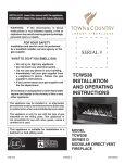
Figure 1-1 shows the components of a typical system. Your system may not
have all the components pictured, or it may have additional or different
components. The numbered items in the figure correspond to the descriptions
that follow.
System Components 1-1
Preparation
Figure 1-1 System Components
1-2 System Components
Preparation
1. Control Unit The backbone of the system, consisting of the basic and
expansion carriers, power supply module, processor module, and line and
station modules. The control unit connects telephone company lines with
stations such as telephones and adjuncts.
2. Line/Trunk and Station Modules. The components that connect telephone
company lines and terminal equipment such as telephones, external alerts,
and fax machines via jacks to the control unit.
3. Basic Carrier. The component attached to the backboard used to hold the
modules needed for system operation. The basic carrier houses the
processor module, power supply module, and up to five line and station
modules. Each expansion carrier houses its own power supply module and
up to six additional line and/or station modules. One or two expansion
carriers can be added.
4. Processor Module. A miniature computer that controls most of the system’s
features and supplies the system’s diagnostics, The processor module
provides two jacks, one for Station Message Detail Recording (SMDR) and
the other for system programming and maintenance via a personal computer
(PC).
5. Power Supply Module. The component that supplies DC power for the
modules and telephones (one power supply unit is needed per carrier). If the
system’s power requirements exceed the capacity of the power supply
module, an auxiliary power supply unit can be added.
6. MLX-20L Telephone with Direct Station Selector (DSS). A console that
adds 50 buttons for one-touch extension dialing to the MLX-20L™ or
MLX-28D™ telephone and speeds call handling.
7. Analog Data Terminal. A data terminal such as a PC, printer, or optical
reader that connects via a modem (for transmitting and receiving analog
signals) to a 012 basic telephone module or a 008 OPT module. A data
terminal can also be connected to an MIX telephone using a Multi-Function
Module (MFM) or to an analog multiline telephone using a General Purpose
Adapter (GPA.)
8. Magic on Hold®. Optional equipment that connects to the system through a
GS/LS jack programmed for Music-on-Hold. (A customer-provided music
source can be connected instead of Magic on Hold.)
9. General Purpose Adapter (GPA). An adapter used to connect a variety of
tip/ring (T/R) adjuncts to an analog multiline telephone (shown here with an
answering machine).
10. Analog Multiline Telephone. A 34-button telephone with built-in
speakerphone that connects to the system via an analog station jack. Other
analog multiline telephones compatible with the system include the 22- and
34-button with built-in speakerphone and a one-line, 16-character display
and the 10- and 22-button with built-in speakerphone, without display.
11. MLC-5 Cordless Telephone. A cordless multiline telephone that connects to
the control unit via an analog station jack.
12. Single-Line Telephone. A touch-tone or rotary industry-standard telephone
connected to the system via a 012 basic telephone module or a 008 OPT
module.
System Components
1-3
Preparation
13. Off-Premises Telephone (OPT). A single-line, touch-tone or rotary, industrystandard telephone located in a different building from the control unit.
14. External Alert. An alerting device such as bells, chimes, and strobe lights
that connect to a jack on a012 basic telephone module or a 008 OPT
module, or to an MFM or Supplemental Alert Adapter (SAA).
15. Digital Data Terminal. A data terminal such as a PC, printer, or optical
reader that connects via an ISDN 7500B Data Module to a 008 MLX module
and that can also include an MDX telephone.
16. MLX-20L™ Telephone. A digital/lSDN (MLX) telephone with 20 line buttons
and a display with seven lines of 24 characters each. The MLX-20L
telephone can also be used as a system programming console. Other MLX
telephones include:
■
MLX-10™/MLX-10D™ Telephone. A 10-button MLX telephone with or
without a two-line, 24-character display,
■
MIX-28D™ Telephone. An MLX telephone with 28 line buttons and a
two-line, 24-character display.
17. MLX-28D Telephone with Multi-Function Module (MFM). A circuit board
mounted inside an MLX telephone that provides a jack to connect equipment
such as answering machines, fax machines, external alerts, and modems to
the telephone.
18. Fax Machine. Industry-standard fax machines connected to the control unit
via a jack on a 012 basic telephone module or a 008 OPT module, an MFM,
or a GPA.
19. SMDR Printer. A printer for Station Message Detail Recording (SMDR) call
records, connected via an RS-232 jack on the processor module.
20. Applications. Software and hardware for MERLIN LEGEND™ Communications System that can connect to the control unit to provide more functions:
■
Call Accounting System (CAS)
■
Call Accounting Terminal (CAT)
■
Call Management System (CMS)
■
MERLIN MAIL™ Voice Messaging System
■
MERLIN® Attendant
■
Integrated Solution II (IS II)
■
Call Accounting System (CAS) — IS II
■
AUDIX® Voice Power — IS II
■
Integrated Voice Power Automated Attendant — lS II
■
MERLIN LEGEND™ System Programming and Maintenance (SPM)
21. Loudspeaker Paging System. A single-zone or multizone system such as
PagePac* with Zonemate† 9 or 39 that connects via an administered jack on
a GS/LS module.
22. AC Power Outlet. A dedicated 115-VAC wall outlet (not controlled by an
on/off switch) that supplies power to the control unit.
* PagePac is a registered trademark of Dracon, a division of Harris Corporation.
† Zonemate is a trademark of Dracon, a division of Harris Corporation.
1-4 System Components
Preparation
Location of the Control Unit
Before installation, choose a room, closet, or other area where the system
control unit can be mounted on the wall. The area must meet the environmental
requirements in Table 1-1.
Table 1-1 Environmental Requirements
Distances
Heat
Dissipation
Power
Requirements
■
Within 25 feet of the network interface (cannot be installed
outdoors)
■
Within 1000 feet of telephones
■
Within 5 feet of a dedicated AC power outlet (1 plug
per carrier)
■
Fully loaded basic carrier:
500 Btu/hr
■
Fully loaded 2-carrier:
1000 Btu/hr
■
Fully loaded 3-carrier:
1500 Btu/hr
■
Basic carrier: 117 VAC 60 Hz ± 1%
160 W 3 amps
■
2-carrier:
117 VAC 60 Hz ± 1%
320 W 6 amps
■
3-carrier:
117 VAC60HZ ± 1%
480 W 9 amps
■
1 properly grounded plug needed per carrier
■
Additional outlets if installing printers
and PCs
Temperature
40°-I04°F; 4°-40°C (optimum temperature 60°F, 16°C)
Humidity
20% - 80% relative humidity
Ventilation
■
Allow at least 1 inch of space on the right and left sides of
the control unit and 12 inches above and below the
control unit to prevent overheating.
Continued
Location of the Control Unit 1-5
Preparation
Table 1-1 Continued
Cautions
The AC outlet for control unit should not be switch
controlled.
■
Plugging the control unit into an outlet that can be turned
on and off by a switch can cause accidental
disconnection of the system.
■
■
The AC outlet must be properly grounded via an AC
receptacle for a 3-prong plug.
Do not install the control unit outdoors.
■
Do not place the control unit near extreme heat (furnaces,
heaters, attics, or direct sunlight).
■
■
■
■
■
■
Do not expose the control unit to devices that generate
electrical interference (such as arc welders or motors).
Each auxiliary power unit requires 1 outlet.
Do not expose the control unit to moisture, corrosive
gases, dust, chemicals, spray paint, or similar materials.
Do not place anything on top of the carriers.
Do not install under any device that may drip fluid, such
as an air conditioner.
In addition, a 3/4-inch plywood backboard is needed to mount the system on
the wall. The dimensions depend on the number of carriers, as shown in
Table 1-2. In some areas, fire or electrical codes require a flame retardant
backboard. Check with the appropriate authorities to ensure that the proper
material is provided.
Table 1-2 Control Unit Space Requirements
Carrier
Dimensions
Basic carrier
Basic carrier + 1 expansion carrier
Basic carrier + 2 expansion carriers
14"w x 23”h x 12"d
25"w x 23"h x 12"d
37”w x 23"h x 12”d
Backboard
Dimensions
Small system (minimum needed)
Large system (minimum needed)
4’w x 3’h x 3/4"d
6’w x 3’h x 3/4”d
It is important that the location you select for the control unit meets all of these
specifications and that the backboard is in place before installation. If you’ve
already selected a location and changes are needed, arrange for these
changes as soon as possible before installation.
1-6 Location of the Control Unit
Preparation
Telephone User Survey
The features and calling privileges you assign to each employee’s telephone
ensure that employees get the most benefit from the system.
If you were not involved in the planning and decision-making for the system, find
out from your management and your AT&T representative or authorized dealer
what telecommunications needs were identified.
To determine calling privileges, get answers to the following questions:
Does management want to allow both local and toll calls to be made from
every telephone?
If any telephones are restricted, are there any numbers the users should be
allowed to call?
Are there any specific numbers (such as 900) that you want to restrict users
from calling?
Who, if anyone, will be given personal lines?
Will access to central office lines be restricted to certain employees?
Do any departments receive frequent special calls (such
as sales and
.
service) so that calls should come to them directly, bypassing a system
operator?
Use the Employee Communication Survey form (see Figure 1-2) to determine
each employee’s telecommunications needs. If it is not feasible to have each
employee fill out a form, get the information you need from a knowledgeable
person in each department, section, or work group. This person should have
sufficient information and authority to make decisions about calling features and
coverage assignments for others in the department.
Make the appropriate number of copies of the Employee Communication Survey
form.
Telephone User Survey 1-7
Preparation
Name
Room
Extension
Name of work group (Sales, Customer Service)
Please answer each question below.
1.
Do you regularly use any of the following outside lines? (Check any that apply)
❑
❑
❑
❑
2.
WATS
FX (foreign exchange)
Tie
None of the above or don’t know
Are your phone calls covered when you’re away from your desk?
❑ No
❑ Yes
3.
By whom?
Do you cover phone calls for co-workers when they are away from their desks?
❑ No
❑ Yes
For whom?
Which of those people should have a button on your phone used
exclusively for his or her calls?
When you are unable to cover calls, it is done by
4.
Do you share the incoming call workload with others?
❑ No
❑ Yes
5.
With whom?
Would you say your phone use is
❑ Heavy
❑ Average
❑ Light
Figure 1-2
Employee Communication Survey Form
1-8 Telephone User Survey
Preparation
6.
Do you have a data terminal or personal computer at your workstation?
❑ No
Do you expect to get one within the next year?
❑ No
❑ Yes
❑ Yes
7.
Do you have a
❑ No
❑ Yes
or ISDN 7500B Data Module?
Do you use account codes for charge-back of calls?
❑ No
❑ Yes
Please list all the codes you use (attach another sheet if necessary):
8.
Approximately how many times do you transfer calls?
9.
Do you need to dial the same number over and over every day?
❑ No
❑ Yes
times/day
Please list these numbers:
10. Do you want to be able to pick up other people’s calls when you hear their phones ring?
❑ No
❑ Yes
Please list these people:
11. DO you want your phone number to appear on another person’s phone for screening, or covering calls, or
for other reasons?
❑ No
❑ Yes
Figure 1-2
Please list these people:
Continued
Telephone User Survey 1-9
Preparation
Use the information in Table 1-3 to interpret and analyze the results of the
Employee Communication Survey.
Table 1-3 Employee Communication Survey — Sample Analysis
1. Types of lines used
Indicates toll calling habits. In most cases, assigning a button for each line is
not necessary.
2. Calls covered by someone
else (sender)
Suggests that this employee should be assigned as a sender in either
Individual or Group Coverage arrangement, particularly if calls are covered
by someone other than the operator.
3. Cover someone else’s calls
(receiver)
Suggests assignment as a receiver in either Individual or Group Coverage
arrangements.
4. Share incoming calls
Identifies calling group needs.
5. Frequency of use
Identifies heavy and light telephone users. Heavy users may benefit from
additional line buttons.
6. Data needs
Identifies existing and potential data terminal and personal computer users.
See the Data Guide.
7. Use of account codes
Identifies current account codes used for charge-back of calls.
8. Frequency of transfers
Suggests the need for one-touch transfer.
9. Frequently dialed numbers
Identifies useful numbers for the System Speed Dial list.
10. Picking up calls
Identifies need for a pickup group.
11. Sharing lines/telephone
numbers
Identifies common personal line appearances.
1-10 Telephone User Survey
Preparation
Floor Plan
Use a floor plan to make planning more manageable and to ensure that the
correct telephone equipment is assigned to each employee.
If your organization is moving to a new location, a floor plan may already be
prepared and you may be able to get a copy of it from your management.
Create a floor plan in two phases:
1. Indicate the location and type of telephones, adjuncts (fax, answering
machines, etc.), and data terminals.
2. When you assign extension numbers, indicate the assigned numbers on the
floor plan.
Note: In this book, telephones and associated adjuncts, such as answering
machines or data terminals, or adjuncts connected directly to the control unit,
are called ‘stations.”
Planning Instructions:
1. Use a large sheet of paper and sketch your office layout. The location of
office walls and other partitions is important when features are assigned
to telephones that must be within hearing range of each other. For example
pickup group members must be able to hear each others' telephones
ringing.
2. Indicate the location of each employee's telephone, other locations where
there will be a telephone (such as in a conference room), and the locations of data terminals, PCs, and host computers. Use the symbols
shown in figure 1-3.
3. Indicate the type of telephone at each location, using an abbreviation that
includes the number of programmable buttons. For example, write "MLX-10"
at 10 button MLX telephones, "MLX-20L" at 20 button MLX display
telephones, "BIS-34" at 34 button Analog multiline telephones, and so forth.
4. Indicate the type of adjunct at each location. Write "fax", ans. mach."
(answering machine), "headset", or other type of adjunct benethe the
symbol.
Floor Plan 1-11
Preparation
Figure 1-3
Floor Plan
As shown in Figure 1-3, the floor plan does not need to be elaborate or to scale.
The telephone symbol should be large enough to accommodate the size of
telephone and the assigned number, and if you find it helpful, the name of the
employee.
Keep the floor plan. You will refer to it during planning and complete it (by filling
in extension numbers) when you get to “System Numbering” in Chapter 2.
1-12 Floor Plan
Control Unit
Planning the control unit consists of deciding how to place the modules, setting
the system operating conditions, and numbering the system.
Modules
Certain modules are required for every system:
■
Processor module contains the memory that controls the system software
and features. It also contains the software and firmware that support built-in
system diagnostics and the built-in data modem used for remote
maintenance and system programming. The processor module is offered in
two sizes:
■
■
The small processor module supports a maximum of 24 lines and/or 56
stations.
The large processor module supports a maximum of 80 lines and/or 144
stations.
■
Power supply module provides power to the processor module and line and
station modules, and to each telephone and adjunct. Each carrier in the
control unit has one power supply module.
■
Line and station modules contain the jacks for connecting stations and
outside lines to the control unit. The type of jack on a module determines the
type of line or station that can be connected to it.
The line and station modules and the type(s) of jacks on each are shown in
Figure 2-1.
Modules 2-1
Control Unit
FIgure 2-1 Line and Station Modules
2-2 Modules
Control Unit
The lines and stations that can be connected to the jack types shown in
Figure 2-1 are described below:
1. A DS1 line jack connects a Digital Signal 1 (DS1) facility provided by the
telephone company. The DS1 facility can be set for either T1 or Integrated
Services Digital Network Primary Rate Interface (ISDN-PRI) operation.
The DS1 facility programmed for T1 operation supplies 24-channel emulation
of any combination of ground-start (GS), loop-start (LS), and tie trunks. When
programmed for ISDN-PRI operation, the channels are used to connect ISDN
services such as Megacom® WATS.
2. Tie-trunk jacks connect private lines from other communications systems.
3. Line jacks (LS) connect loop-start lines from the telephone company.
4. Power failure transfer (PFT) jacks connect single-line telephones that work
during power failures. Analog multiline telephones and digital/lSDN (MLX)
telephones cannot be used as power failure telephones.
5. Line jacks (GS/LS) connect loop-start or ground-start lines from the
telephone company.
6. Off-premises telephone (OPT) jacks connect off-premises tip/ring equipment
such as single-line telephones, fax machines, or answering machines.
Tip/ring equipment connects directly to an outside line and works on a single
pair of wires.
7. Analog station jacks connect analog multiline telephones and adjuncts.
See the Data Guide for more information
on data stations.
8. Digital station jacks connect MLX telephones or data devices such as the
ISDN 7500B Data Module.
9. Basic telephone station jacks connect tip/ring equipment such as single-line
telephones, fax machines, or answering machines. Basic telephone station
jacks also connect optional applications such as MERLIN Attendant or
MERLIN MAIL Voice Messaging System for the MERLIN LEGEND
Communications System.
Table 2-1 shows the capacities of each module.
Modules 2-3
Control Unit
Table 2-1
Modules Capacities
Station Jacks
Modules
Line Jacks
100D
1 DS1 facility (ISDN-PRI or T1)
400EM
4 4-wire E&M tie trunks
400
4 LS linrs with 4 TTR*
1 PFT jack
400 GS/LS/TTR
4 GS/LS lines with 4 TTR*
1 PFT jack
800
8 LS lines
2 PFT jacks
008 OPT
2 TTR*
8 OPT jacks
800 GS/LS
8 GS/LS lines
2 PFT jacks
008
8 analog jacks
008 MLX
8 digital jacks
012
2 TTR*
12 basik jacks
408
4 LS lines
8 analog jacks, 1 PFT jack
408 GS/LS
4 GS/LS lines
8 analog jacks, 1 PFT jack
* TTR = Touch-tone receivers required for tip/ring equipment and Remote Access. TTRs are not used to connect lines.
Line and Station Capacity
The numbers of jacks in Table 2-1 are the physical jacks on each module. In
most cases, the number of physical jacks indicates capacity (the number of
lines and/or stations that can be connected to the module). The exception is the
100D module with one physical jack which, because of the system’s software
capabilities, supports 24 lines.
Use the AT&T Equipment List (supplied with your communications system)
to complete page 1 of Key System Form 1, System Planning.
Planning Form Instructions:
Under the heading "Size of Processor Module" check the box describing the
size of the processor module (small or large).
Under the "Lines" heading in the "Capacity" section:
1. Fill in the number of each type of line module in the appropriate area.
2. Add the "Number of Modules" column and record the result next to the
system totals.
3. Multiply the number of each type of module by the number of lines it supports.
Write the results in the appropriate line of the "Total Lines by Module Type" column.
4. Add the "Total Lines by Module Type" column and record the total line
capacity of the system.
2-4 Modules
Control Unit
Station capacity is the number of stations that can be connected to the control
unit, and it equals the number of physical jacks on the line and station modules.
See “System Numbering” in this chapter
for detailed information.
One extension number is automatically assigned to each station jack, whether or
not equipment is connected to it, except for the 008 MLX and 008 OPT modules:
■
008 MLX module has two extension numbers assigned to each physical
jack, the first for a digital/lSDN (MLX) telephone and the second for any
equipment connected to the telephone through an MFM.
■
008 OPT module has eight physical jacks, which the system reads as 12
jacks and assigns an extension number to each.
Planning Form Instructions
Under the heading "Stations":
1. Fill in the numbers of each type of station module on the appropriate
lines.
2. Add the "Number of Modules" column and record the result by the system
totals.
3. Multiply the number of each type of module by the number of physical
jacks on it and record the results.
4. Add the "Physical Jacks by Module Type" column and fill in the "System
Totals" line to show station capacity.
5. To determine the number of extensions assigned, multiply the number of
physical jacks by module type, by the number of station extensions the
system assigns to each module's jack type.
Note: Since the system assigns an additional four extensions to each 008
OPT module, you must multiply the number of 008 OPT modules by four
and add this subtotal to the result shown in the "Physical Jacks by Module
Type" column.
6. Write the results in the "Total Station Extensions Assigned" column.
7. Add the "Total Station Extensions Assigned" column and fill in the "System
Totals" line.
Module Placement
Use the “Control Unit Diagram” on Key System Form 1 and the following
guidelines to plan where the modules an placed in the control unit:
■
Put the power supply module in the far left slot of each carrier.
■
Put the processor module in slot 00 of the basic carrier.
■
Put line and station modules in any order in slots 01 through 17, with the
following conditions:
■
Put the modules in each carrier from left to right with no empty slots
between modules. (The system does not recognize modules in slots after
an empty slot; slots to the right of the last module can be left empty.)
Modules 2 - 5
Control Unit
■
Group all 100D and 400EM modules together according to type,
whenever possible, to save time in system programming.
Each physical jack on the control unit is numbered sequentially from left to right
and bottom to top:
■
Station jacks are numbered from 1 to 144.
■
Line jacks are numbered from 1 to 80.
This sequence of numbers is called the "logical ID." It is the basis for how you
connect components to the control unit, as well as how the system assigns
station extension numbers and line numbers.
Notes:
■
Each 100D module is assigned 24 logical IDs even though the module has
only one physical line jack.
■
The 008 OPT module is assigned 12 logical IDs even though the module has
only eight physical station jacks.
■
Power failure transfer (PFT) jacks are not assigned logical IDs.
Planning Form Instructions
Mark the module placement on the "Control Unit Diagram" on the back of
Form 1.
1. Write the type of module to be installed at the top of each slot. Use the
lables listed in Table 2-1 (008 MLX, 408, etc.)
2. Write the type of jack (S= Station, L = Line) and the associated logical ID
for each line and station jack on each module.
Notes:
■
The "Unit Load" and "Auxiliary Power" blocks above the diagram are
reserved for occasions when equipment changes or maintenance require
the installation technician to manually compute the values. See System
Reference for details on computing unit loads.
■
Logical ID labels for each line and ststion jack are provided with the
system. When the control unit is assembled, the labels are attached to the
modules.
Figure 2-2 shows a completed “Control Unit Diagram" for a system with a large
processor module with 32 lines and 52 stations.
2-6 Modules
Control Unit
Figure 2-2
Sample Control Unit Diagram
Modules 2 - 7
Control Unit
System Operating Conditions
Use the “Control Unit Diagram” on Key System Form 1 as a reference and
mark the “System Operating Condtions” section of that form.
Record the following system operating conditions:
■
programming equipment that will be used and its station jack assignment
■
mode of operation
■
whether Automatic Maintenance Busy is enabled
■
a reminder to set the system time and date
Programming Equipment and Station Jack Assignment
Two types of equipment can be used for system programming:
■
an MIX-20L telephone acting as a system programming console. The
telephone is the first (lowest) station jack on the first MLX module and is
factory set for system programming.
■
a personal computer (PC) with MERLIN LEGEND System Programming and
Maintenance (SPM) software. (Both DOS and UNIX based SPM are
available.) The PC is connected to the lower jack on the processor module.
Use these instructions only if using a system programming console.
Planning Form Instrructions
Under the heading "System Programming Console" onForm 1:
1. Do one of the following:
■
Check "NO" if you are using a PC with SPM to program the system. Go to
the "Mode of Operation" instructions.
■
Enter the Logical ID and Extension Number if you are using a system
programming console.
2. To change the factory-set system programmin jack, write in the new
logical ID (using information from the "Control Unit Diagram").
Note: You will fill in the extension number of the jack later.
In addition to being factory set for system programming, the first (lowest) station
jack on the first MLX module is also factory set as the primary operator position.
Since the primary operator position cannot be reassigned to another station
jack, you may want to change the system programming assignment to ensure
that future programming sessions do not interfere with the operator’s work.
If you want the system programming jack to be different from that of a system
operator, change the programming assignment to any one of station jacks 2
through 5 on the first MLX module in the control unit.
2-8 System Operating Conditions
Control Unit
Mode of Operation
See System Reference for more
information on modes.
Your system is registered with the FCC to operate as a Key system. However,
you can program the system to operate in any of three modes:
■ Hybrid/PBX
■
Key (the factory setting)
■
Behind Switch
The mode of operation determines
■
how outside lines are provided to users
■
the types of operator consoles allowed
■
the features available and how they work.
Note: This book applies only to systems in the Key and Behind Switch modes.
To plan a system in the Hybrid/PBX mode, use PBX System P/arming.
Key Mode
In the Key mode, every line appears on a separate button on each multiline
telephone. The line buttons allow users to see activity on other telephones, join
conversations, place calls, or receive calls. Separate intercom buttons are used
to make and receive internal calls.
A Key system automatically assigns the first eight outside lines to all telephones.
You can customize this arrangement through system programming by assigning
lines or groups of lines to selected groups of telephones or to individual
telephones.
Behind Switch Mode
The Behind Switch mode is used when the system is connected to another
telephone system or Centrex. This other system (called the "host") provides the
interface to outside lines and some features.
A Behind Switch system assigns only one line (called a "prime line”) to each
telephone. You must assign outside lines to telephones or groups of telephones
through programming.
In the Behind Switch mode, people can use the special features of both this
system and the host system. Compare the host systems feature list and your
system to determine which features the two systems have in common.
Once you have determined common features, decide whether you want people
to use the features following your system’s instructions or following the host
system’s instructions. (If you decide that the host instructions are to be used,
they must be distributed to telephone users.) In the Behind Switch mode, when
users press the Conference, Drop or Transfer buttons, a signal is sent to the
host system. Get the host system dial code for each of these buttons so that
users can take advantage of these features using the host system.
System Operating Conditions 2-9
Control Unit
In the Behind Switch mode single-line telephones can be programmed to select
only the prime line (the user cannot make inside calls or use system features) or
to select the intercom button followed by the prime line or outside line (the user
can place and receive inside calls and use system features).
Planning Form Instructions
Under the "Set System Mode" heading on Form 1:
1.
Check "Key" if you want your system to operate in the Key mode.
2.
Check "Behind Switch" if your system is connected behind a larger
system. Write the host's dial code for the Conference. Drop, and Transfer
features.
Automatic Maintenance Busy
Automatic Maintenance Busy puts a malfunctioning line in a ‘maintenance busy”
state, preventing outgoing calls on that line. Incoming calls are never blocked. A
line in maintenance busy is tested by the internal maintenance software to try to
put it back into service.
The factory setting for Automatic Maintenance Busy is ‘disabled,” which means
that faulty lines are not automatically put in a maintenance busy state. The
factory setting, disabled, is satisfactory for most Key and Behind Switch
Systems.
Planning Form Instructions
Under the "Automatic Maintenance Busy" heading on Form 1:
1. Do one of the following:
■
Check "Disable" to keep the factory setting.
■
Check the second box to enable Automatic Maintenance Busy.
System Date and Time
See “System Features” in Chapter 4 for
information on SMDR.
The system date and time is the month, day, year, and time shown on display
telephones and Station Message Detail Recording (SMDR) reports. The system
date and time is also shown on error reports used by AT&T or an authorized
representative for maintenance.
Planning Form Instructions
Check "Yes" under both "Set System Date" and "Set System Time" headings
on Form 1 as a reminder to set current date and time.
2-10 System Operating Conditions
Control Unit
System Numbering
System numbering is the process of assigning extension numbers to stations
(telephones and adjuncts), calling groups, paging groups, Park zones, and
Remote Access.
The instructions is this chapter deal only with assigning extension numbers to
stations.
Number the stations in two stages:
Stage One. Decide in what order to connect the telephones and other
equipment to the control unit. To do this, identify station jack types and
match individual components with the jacks that support them.
When the system is turned on, it identifies the type of module installed in
each control unit slot and automatically assigns extension numbers to the
components in exactly the same order in which they are connected to the
control unit. As you plan connections, therefore, you should be aware of the
relationship between the jack’s logical ID and the extension number the
system assigns.
The stations are assigned 2-digit extension numbers starting with extension
10 at the station jack with the logical ID of 1. If a user needs a specific
extension number, it is simpler (in terms of programming) to connect that
user’s telephone to the station jack that is automatically assigned the
requested extension number.
Stage Two. Decide if the system-assigned extension numbers are
appropriate or if you should renumber all, or some, of the extensions
assigned to the stations.
The system offers three predetermined numbering plans. In addition, you
have the option of creating your own unique numbering plan with extensions
of one to four digits.
Locate and review your Floor Plan and AT&T Equipment List to verify the
equipment you have and how many of each kind of connection are needed.
Record equipment connections and extension numbers on Key System Form
2a, System Numbering — Station Jacks.
Note: Form 2a is a multipage list that accommodates entries for up to 144
stations. It shows the logical IDs for each station, as well as the three
predetermined numbering plans available.
You also need Key System Form 1, System Planning, for both reference and
to make additional entries.
System Numbering 2-11
Control Unit
Station Jack Connections
Planning station jack connections consists of identifying the jack types and
matching the telephones and other equipment to the jacks that support them.
Determine the station jack types in the control unit and plan connections in the
following order:
primary operator position
additional operator positions
Voice Announce to Busy and/or Simultaneous Voice and Data
digital/lSDN (MLX) telephones
analog multiline telephones
tip/ring equipment
applications
Station Jack Types
Station jack type is determined by the module type. The station jack types and
the equipment that can be connected to these jacks are listed in Table 2-2.
Use the completed “Control Unit Diagram” (Form 1) and Table 2-2 for
reference and mark the station jack types on Form 2a.
Table 2-2 Station Jack Types
2-12 System Numbering
Station
Jack Type
Module
Type
Analog
008
408
408 GS/LS
Analog multiline teletphones
Call Management System (CMS)
Digital
008 MLX
Digital/ISDN (MLX) teltphones
Digital data devices, such as ISDN 7500B
Data Modules
Basic
Telephone
012
Tip/ring equipment:
Single-line telephones
Adjuncts, such as answering ot fax
mashines
Analog data devices, such as modems
Optional applications:
MERLIN Attendant
MERLIN MAIL Voice Messaging System
AUDIX Voice Power — IS II
Integrated Voice Power Automated
Attendant — IS II
008 OPT
Tip/ring equipment in another building or
off-premises
Used to Connect
Control Unit
Planning Form Instructions
In the "Jack Type" column of Form 2a, indicate the type of each station jack
next to its logical ID.
Jacks for Primary Operator
Position
1 .
Check "A" if the jack is Analog, "D" if Digital, or "B" if Basic telephone.
2 .
The system reserves 12 logical IDs for the 008 OPT module even though
only 8 are used. Cross off the last 4 logical IDs (they cannot be used).
The factory setting for the primary operator position is the lowest station jack on
the first 008 MLX module. If the system doesn’t have an MLX module, it’s the
lowest station jack on the first module with analog station jacks. The factory
setting for the primary operator position cannot be changed.
On the primary operator position direct-line console (DLC), lines are assigned
on individual buttons. The console can have several calls ringing at the same
time.
DLCs can be assigned to either a digital or analog station jack.
Planning Form Instructions
Mark jack assignments on Form 2a.
If the system does not include a system programming console, go to step 4.
1 . See the "System Operating Conditions" on the back of Form 1 for the
logical ID of the station jack for the system programming console.
2 . Mark the "Logical ID" column of Form 2a by writing "SPC" beside the
preprinted logical ID for the system programming console station jack.
3 . Write the name of the person who will be programming or the location of
the system programming console in the "Person, Location, or Function"
column.
4 . Locate the first station jack showing a "D" (digital or "A" (analog) type and
write "DLC" beside the preprinted logical ID to indicate the primary DLC
operator position.
5 . Write the name or location of the primary DLC operator in the "Person,
Location, or Function" column.
Jacks for Additional
Operator Positions
Use these instructions only if the system has more than one operator
position.
The maximum numbers of operator positions are shown in Table 2-3.
System Numbering 2-13
Control Unit
Table 2-3 Maximum Number of Operator Positions
Telephone
Type
Processor
Module Size
MLX-20L
MLX-28D
Small
6
MLX-20L
MLX-28D
Large
8
Analog multiline telephones
Small or Large
8
Maximum
Positions
Assign DLCs to only the first and fifth station jacks on a digital or analog module.
This includes DLC positions used for calling group supervisors and for the
optional Call Management System (CMS).
The CMS equipment is connected to analog station jacks that are assigned as
DLC positions. You must assign two DLC positions for each CMS (a maximum of
two) connected to the system.
Planning Form Instructions
Use the "Control Unit Diagram" on Form 1, to determine which station jacks
can be used as operator positions.
Station Jacks Pairs
1.
Circle the first and fifth station jacks on each digital or analog module on
the "Control Unit Diagram" until you have reached themaximum eight
positions.
2.
Mark the station jacks to be used as additional operator positions in the
shaded boxes on Form 2a.
3.
Write "DLC" beside the preprinted logical ID of each position. Be sure to
assign DLCs to only the first and fifth station jacks on each digital or
analog module.
4.
Write the name or location of each additional DLC operator in the "Person,
Location, or Function" column.
5.
If the systemincludes the Call Management System(s), write "CMS" in the
"Person, Location, or Function: column next to the logical ID for the two
DLC positions assigned for each CMS.
These instructions apply only to systems with analog muitiline telephones.
Two of the optional features for analog multiline telephones require an additional
station jack:
■
2-14 System Numbering
Voice Announce to Busy. A user whose telephone has this feature can hear
an announcement through the speaker even though he or she is on a call.
(MLX telephones can also use this feature but do not need an additional
station jack. Single-line telephones cannot use this feature since they do not
have speakers.)
Control Unit
■
Simultaneous Voice and Data. A user whose telephone has this feature can
use the telephone and a data terminal at the same time. (MLX telephones
have this feature without requiring a second station jack.)
An analog multiline telephone with either one of these features requires two
consecutive analog station jacks on the control unit. The jacks are an oddnumbered analog station jack and the next higher (even-numbered) analog
station jack.
The system assigns individual extension numbers to each of the jacks for either
the Voice Announce to Busy or the Simultaneous Voice and Data feature. The
extension number associated with the first (odd-numbered) station jack in the
pair is the telephone’s extension number. Calls cannot be placed to the
extension number associated with the even-numbered station jack.
You can assign either of these features to any of the analog multiline telephones
in the system, but you cannot assign both to the same telephone.
Planning Form Instructions
On Form 2a, mark the pairs of jacks for analog multiline telephones that have
the Voice Announce to Busy or Simultaneous Voice and Data feature.
1.
In the "Logical ID" column, draw a box around the pair of ststion jack
numbers that you plan to assign to each analog multiline station with
eather feature.
2.
In the "Person, Location, or Function" column, next to the first (odd)
number of each boxed pair, identify the station by person or location.
3.
In the "Person, Location, or Function" column, next to the second (even)
number of each boxed pair, write "Voice/Voice" for Voice Announce to
Busy feature or "Voice/Data" for the Simultaneous Voice and Data feature.
Jacks for Digital/ISDN
(MLX) Telephones
Use these instructions only if the system has non-operator MLX telephones
to assign to digital station jacks on 008 MLX modules.
Use the instructions in the Data Guide
Although only one logical ID is assigned to each digital station jack, the system
assigns two extension numbers. The extension number on Form 2a is the
extension number automatically assigned to an MLX telephone connected to the
digital station jack. The second extension number is reserved for an adjunct
such as an answering machine that may be connected to the MLX telephone via
a Multi-Function Module (MFM) or for an ISDN 7500B Data Module used to
connect a data terminal.
to plan connections for digital data
equipment.
The system automatically assigns both extension numbers whether or not the
station includes an MFM or data module. Calls can be placed to both extension
numbers independently.
The MFM can operate as either a Supplemental Alert Adapter (SAA) or as a
tip/ring interface. The adapter is used when the MFM connects an external alert
such as a bell or horn. The tip/ring interface, is used when the MFM connects a
tip/ring device such as an answering machine or modem.
System Numbering 2-15
Control Unit
Planning Form Instructions
Use the Floor Plan and AT&T Equipment List to verify that you have
located all remaining MLX telephones and adjuncts to them.
On Form 2a, mark the station jack assignments for the remaining MLX
telephones:
1.
In the "Jack Type" column, make sure there is a "D" checked next to the
logical ID for each digital station jack.
2.
In the "Person, Location, or Function" column, identify each MLX telephone
by person, location, or function.
Use the information from Form 2a as you mark the adjuncts on Key System
Form 2b, System Numbering — Digital/ISDN Station Adjuncts.
3.
In the "Logical ID" column, write the logical ID of each digital station jack
(D jack type).
Note: You will fill in the "Factory - Set Extension No." column later.
Complete the "MFM" and "7500B" columns:
Jacks for Analog Multiline
Telephones
4.
If the jack does not have an adjunct, write "NONE" across the columns.
5.
If an adjunct is connected to the MLX telephone:
■
Check the "7500B" column if the station includes the data module.
■
Check "SAA" or "T/R" in the "MFM" column to show how the MFM
connects the adjunct.
6.
Complete the last column.
7.
Identify each adjunct or data module by type and by person, location, or
function.
Use these instructions only if the system includes the 408, 408 GS/LS, or
008 modules.
Assign analog station jacks for all remaining non-operator analog multiline
telephones in the system.
Planning Form Instructions
On Form 2a, mark the station jack assignments for the remaining analog
multiline telephones.
2-16 System Numbering
1.
In the "Jack Type" column, make sure there is an "A" checked next to the
logical ID for each analog station jack.
2.
In the "Person, Location, or Function" column, identify each analog
multiline telephone by person, location or function.
Control Unit
Jacks for Tip/Ring
Equipment and
Applications
See System Reference for more
information on applications.
Use these instructions only if the system includes 012 or 008 OPT modules.
Assign the basic telephone jacks on the 012 or 008 OPT modules to any tip/ring
equipment such as single-line telephones, fax machines, or answering
machines. Tip/ring equipment connects directly to an outside line and works on
a single pair of wires. When connected to a 008 OPT module, the tip/ring
equipment can be located off-premises.
Several optional applications, if used with the system, require a basic jack on a
012 module: MERLIN MAIL Voice Messaging System, MERLIN Attendant,
AUDIX Voice Power — lS II, and Integrated Voice Power Automated Attendant
— IS Il.
Up to four applications can be connected to the system using the same 012
module. If there are four applications, the module must be used exclusively
for this equipment If you have fewer than four applications connected to an
012 module, some tip/ring devices also can be connected. If possible, the
module should be used only for the application equipment.
Note: The applications discussed here do not work properly with 012 module
manufactured for older MERLIN® II systems. These applications must be
connected to 012 modules with the code 517C13 or 517D13 on the label on the
top of the module. Modules with the code 517A13 or 517B13 can be used only
to connect single-line telephones and do not provide the disconnect signal
required by answering machines and applications.
Planning Form Instructions
On Form 2a, mark the station jack assignments on the 012 and 008 OPT
modules.
1.
In the "Jack Type" column, make sure there is a "B" checked next to the
logical ID for each basic telephone jack.
2 . In the "Person, Location, or Function" column, identify each tip/ring device
by person or location, and by type, such as single - line telephone, fax, or
answering machine.
3.
If the system includes optional applications indicate the type of
application in the "Person, Location, or Function" column:
■
Write "Mail" to indicate MERLIN MAIL Voice Messaging System.
■
Write "MERLIN A" to indiccate MERLIN LEGEND Attendant.
■
Write "AVP" to indicate AUDIX Voice Power — IS II.
■
Write "IVP - AA" to indicate Integrated Voice Power Automated
Attendant — IS II.
System Numbering 2-17
Control Unit
System Renumbering
Use these instructions to decide whether to keep the factory-set extension
numbers or to change them to numbers taylored to your company — for
example, extension numbers that match room numbers.
The system offers three numbering plans, as shown on Form 2a, System
Numbering — Station Jacks. Each plan allows you to renumber all or selected
extensions.
■
Two-Digit — designed for systems with fewer than 50 stations at businesses
that do not anticipate growth to more than 50 stations in the next one or two
years. The two-digit numbering plan is the factory setting.
■
Three-Digit — designed for businesses with more than 50 stations.
■
Set Up Space — designed for businesses that want to customize numbering
and assign 1 to 4 digit extensions that are more convenient for users. As an
example, hotels and motels may want to renumber extensions to match room
numbers and to renumber services numbers (such as Housekeeping or
Room Service) to 1-digit extension numbers.
When you reassign extension numbers, keep the following in mind:
■
Extension numbers can contain the digits 0 through 9 in any combination,
except that no extension number can begin with 0. (The 0 is a fixed dial code
representing the primary operator.)
■
Extension numbers can contain one to four digits and must be unique, If you
assign an extension number with one or two digits, you cannot use those
digits as the leading digits for a longer extension number, For example, if you
assign extension numbers 1, 2, 30, and 40, you cannot use those numbers
as the first number in longer extension numbers such as 10, 200, 302, or
4052.
■
The system-assigned numbers in the shaded areas of the figures on the
following pages are automatically reserved. To use any of these numbers for
a different station, you must assign a new extension to the station that
already has the number you need to use.
■
When you reassign an extension number, the extension number vacated is
free for you to use.
Select the numbering plan that fits your needs and use the appropriate
plan-specific instructions that follow to mark Forms 2a and 2b with your
extension number assignments.
Two-Digit Numbering Plan
2-18 System Numbering
The extension numbers you assign according to the factory-set two-digit
numbering plan are shown in Figure 2-3. The numbers are arranged in blocks
according to the first digit. The type of equipment or feature to which they are
assigned is shown in the block.
Control Unit
Operator Console (not flexible)
0
Stations
10 — 19
Stations
20 — 29
Stations
30 — 39
Stations
40 — 49
Stations
50 — 59
0
1
2
3
4
5
6
7
8
9
Main Pool
7 0
A
Extra Stations
Stations
60 — 67
6800 — 6885
MFMs & 7500Bs
Calling Group
710 — 767
770 — 791, 7920 — 7929
Park
Lines
801 — 880
881 — 888
ARS Access (Hybred/PBX Mode)/Idle Line Access
9
Extra Adjunct
6900 — 6985
Page
793 — 799
Pools
B
890 — 899
Figure 2-3 Two-Digit Numbering Plan
A = 800-Listed Directory Number
B = 889—Remote Access
Each of the first 58 station jacks is assigned a 2-digit extension number
beginning with extension 10 and ending with extension number 67. The rest of
the stations (68–144) are assigned 4-digit extension numbers 6800–6885. Extra
adjuncts are assigned as extensions 6900–6985.
The extension numbers shown for MFMs/7500Bs (710–767) are resewed for a
station adjunct connected to an MLX telephone such as a data terminal
connected through an ISDN 7500B Data Module or an answering machine
connected using an MFM. The extension numbers are resewed whether or not
an adjunct is connected to the telephone.
For the first 58 digital station jacks, the actual extension number assigned to the
adjunct is the extension number assigned to the MIX telephone preceded by
a 7. For example, if the extension number assigned to an MIX telephone is 25,
the extension number assigned to the adjunct on that telephone is 725. In this
example, a call can be placed to the telephone by dialing extension 25 or to the
adjunct by dialing extension 725. If you reassign the extension number of the
telephone, the system does not automatically change the extension number of
the MFM or data module.
See the CMS documentation for more
information on reassigning numbers for
CMS agent splits.
Note: If your system includes the CMS, it assigns extension numbers to agent
splits.
System Numbering 2-19
Control Unit
The unshaded areas of the two-digit numbering plan in Figure 2-3 indicate the
extension numbers available for reassignment. This means that you can change
selected extension numbers to one of the available numbers, for example,
extensions 6886 through 6899. If the available numbers shown do not meet your
needs, consider the three-digit numbering plan.
Planning Form Instructions
Use Figure 2-3 as you record extension number information.
1.
2.
3.
Three Digit Numbering
Plan
2-20 System Numbering
If the system includes digital station adjuncts.
■
Locate Key System Form 2b, System Numbering — Digital/ISDN
Station Adjuncts.
■
Write the 3 digit extension number — the extension number from Form 2a
with a "7" preceding it — in the "Factory - Set Extension No." column of
Form 2b.
If you do not need to renumber any of the factory - set extension numbers:
■
Check the "2 - Digit" box under the "Renumber To" heading onForm 2a.
■
Go to the "Form and Floor Plan Update" instructions later in this
chapter.
If you want to renumber only a few of teh extensions, and enough
numbers are available.
■
Check the "2 Digit" and "Selected Extension Numbers" boxes under the
"Renumber System" heading of Form 2a.
■
Write the new extension number(s) in the "Renumber To" column on
Form 2a and Form 2b.
■
Go to the "Form and Floor Plan Update" instructions later in this
chapter.
Figure 2-4 shows the numbers automatically assigned by the system when you
renumber with the three-digit numbering plan. The numbers in the figure are
arranged in blocks according to the first digit. The type of equipment or feature
to which they are assigned is shown in the block.
Control Unit
Operator Console (not flexable)
0
Stations
100—199
0
1
2
Stations
200—243
MFMs/7500Bs
300—399
3
MFMs / 7500Bs
400 — 443
4
5
6
Main Pool
70
7
8
A
9
Calling Group
Page
770— 791, 7920—7929 793—799
L i n e s
Park
Pools
801—879
890—899
881—888 B
ARS Access (hybred/PBX Mode)/Idle Line Access
9
Figure 2-4 Three-Digit Numbering Plan
A = 800—Listed Directory Number
B = 889—Remote Access
All stations are assigned a 3-digit extension number beginning with extension
100 and ending with extension 243.
The extension numbers shown for MFMs/7500Bs (300–443) are reserved for
station adjuncts connected to an MLX telephone such as a data terminal
connected through an ISDN 7500B Data Module or an answering machine
connected using an MFM. The extension numbers are resewed whether or not
an adjunct is connected to the telephone.
The actual extension number assigned to the adjunct is the extension number
assigned to the MLX telephone increased by 200, For example, if the extension
number assigned to an MLX telephone is 125, the extension number assigned
to the adjunct on that telephone is 325. In this example, a call can be placed to
the telephone by dialing extension 125 or to the adjunct by dialing extension
325. If you reassign the-extension number of the telephone, the system does not
automatically change the extension number of the MFM or data module.
See the CMS documentation for more
information on reassigning numbers for
CMS agent splits.
Note: If your system includes the CMS, it assigns extension numbers to agent
splits.
System Numbering 2-21
Control Unit
The unshaded areas of the three-digit numbering plan in Figure 2-4 indicate the
extension numbers available for reassignment. This means you can change the
extension number automatically assigned by the system to one of the available
numbers, for example, extension number 244 through 299. If the available
numbers shown are not adequate to meet your needs, consider the set up
space numbering plan.
Planning Form Instructions
Use Figure 2-4 as you record the extension number information.
1 . If the system includes digital station adjuncts:
■
Locate Key System Form 2b, System Numbering — Digital/ISDN
Station Adjuncts.
■
Write the 3-digit extension number—the extentsion number from Form 2a
increased by 200 (within the range 300-443)—in the "Factory-Set
Extension No." column of Form 2b.
2 . If you do not have to renumber any of the 3-digit extension numbers:
■
■
Check the "3-Digit" box under the "Renumber System" heading on
Form 2a.
Go to the "Form and Floor Plan Update" instructions later in this
chapter.
3 . If you want to renumber only a few of the 3-digit extensions and enough
numbers are available in the three-digit numbering plan:
Set Up Space Numbering
Plan
2-22 System Numbering
■
Check the "3-Digit" and "Selected Extension Numbers" boxes under the
"Renumber System" heading on Form 2a.
■
Write the new extension number(s) in the "Renumber To" column on
both Form 2a and Form 2b.
■
Go to the "Form and Floor Plan Update" instructions later in this
chapter.
Figure 2-5 shows the numbers automatically assigned when the system is
renumbered using the set up space numbering plan. The numbers in the figure
are arranged according to the first digit. The type of equipment or feature to
which they are assigned is shown in the block.
Control Unit
Operator Console (not flexible)
0
0
1
2
3
4
5
6
7
Main Pool
8
A
70
Stations
MFMs/7500Bs
7100—7243
Calling Group
Page
7300—7443
770—791, 7920—7929
793—799
9
Park
Lines
881—888
801—880
B
Pools
890—899
ARS Access (Hybrid/PBX Mode) /Idle Line Access
9
Figure 2-5 Set Up Space Numbering Plan
A = 800—Listed Directory Number
B = 889—Remote Access
As shown in Figure 2-5, the system assigns extension numbers in the 7100 to
7243 range to stations. This makes numbers beginning with 1 through 6
available for use in reassigning extension numbers. These new extensions can
be from one to four digits long. The unshaded areas of the setup space
numbering plan in Figure 2-5 indicate the extension numbers available for
reassignment.
The extension numbers shown for MFMs/7500Bs (7300–7443) are resewed for
station adjuncts connected to an MLX telephone, such as a data terminal
connected through an ISDN 7500B Data Module or an answering machine
connected using an MFM. The extension numbers are reserved whether or not
an adjunct is connected to the telephone.
The actual extension number assigned to the adjunct is the extension number
assigned to the MLX telephone increased by 200. For example, if the extension
number assigned to an MLX telephone is 7125, the extension number assigned
to the adjunct on that telephone is 7325. In this example, a call can be placed to
the telephone by dialing extension 7125 or to the adjunct by dialing extension
7325. If you reassign the extension number of the telephone, the system does
not automatically change the extension number of the MFM or data module.
See the CMS documentation for more
information on reassigning numbers for
CMS agent splits.
Note: If your system includes the CMS, it assigns extension numbers to agent
splits.
System Numbering 2-23
Control Unit
Planning Form Instructions
Use Figure 2-5 as you record extension number information.
1 . If the system includes Digital station adjuncts:
■
Locate Key System Form 2b, System Numbering — Digital/ISDN
Ststion Adjuncts.
■
Write the 4-digit extension number — the extension number from Form 2a
increaed by 200 (within the range 7300–7443)—in the "Factory Set
Extension No" column of Form 2b.
2 . Under the "Renumber System" heading of Key System Form 2a:
■
Check "Set Up Space.".
■
Write the new extension number(s) in the "Renumber To" column on
both Form 2a and Form 2b.
Form and Floor Plan Update
Make sure that your system numbering plan decisions are recorded on all the
appropriate forms.
Planning Form Instructions
On the Floor Plan, add the extension numbers you have assigned underneath
the description of the telephones (such as MLX-10 or BIS-34) and adjuncts.
On Key System Form 1, System Planning, in the "System Operating Conditions"
section, if you are using a system programming console, add the new
extension number of the console in the space next to the "Ext. No.".
2-24 System Numbering
Lines
Planning for lines consists of deciding how to connect outside lines to the
system, selecting options for how those lines will work, and assigning lines to
user stations.
Line Connections
Plan line connections by identifying line jack types and matching outside lines
and auxiliary equipment to the jack types that support them.
Use the “Control Unit Diagram” on Key System Form 1 and the local
telephone company line information list as you record connections on Key
System Form 2c, System Numbering — Line Jacks.
Line Jack Types
The line jack type is determined by the type of module. The following table
shows the line jack types, the module types that contain them, and the outside
line or equipment they support.
Line Connections 3-1
Lines
Table 3-1 Line Jack Types
Used to Connect
Line Jack Type
Module Type
Loop-start (LS)
400
800
408
Ground-start/Loop-start
(GS/LS)
400 GS/LS/TTR
800 GS/LS
408 GS/LS
Line Type
■
■
■
■
Equipment
Basic
Special purpose
— FX, WATS
Music-on-Hold
Loudspeaker paging systems
Maintenance Alarm
Basic
Special purpose
— FX, WATS
Music-on-Hold
Loudspeaker paging systems
Maintenance Alarm
Tie
400EM
Tie
DS1
100D
T1
ISDN-PRI
If the system has 1OOD (DS1) modules, keep in mind that 24 logical IDs and
associated line numbers are assigned to each module.
See “DSI Facility (100D Module)” later in
this chapter for information on ISDN-PRI
services.
When the system is first set up, it automatically assigns the T1 type to the facility
connected on a 100D module. This means you can dedicate the channels for
use as T1-type lines and use the channels to emulate any combination of loopstart, ground-start lines, and/or tie trunks. If this is the case, your local telephone
company supplies the telephone numbers associated with each of the channels
on the DS1 facility.
You can also connect certain digital services such as Megacom® 800 to the T1type facility or change the module’s service type to ISDN Primary Rate Interface
(ISDN-PRI) to allow connection of services such as Accunet® Switched Digital
Service.
Note: You cannot mix T1 and ISDN-PRI types of service on the same 100D
module.
3-2 Line Connections
Lines
Planning Form Instructions
Review the module listed on the "Contrrol Unit Diagram" on Form 1.
On Key System Form 2c, System Numbering — Line Jacks:
1. Write the type of each line jack in the control unit in the "Jack Type"
column. Use the codes shown in Table 3-2.
For systems that include the 100D module:
2.
3.
If the module is used only to emulate lines:
■
Fill in the jack type codes for those lines (T1-GS, T1-LS, or T1-Tie).
■
Write only "T1" in the "Jack Type" column for any of the channels not
used at this time.
If the module is used to connect services:
■
Write "T1-Tie" in the "Jack Type" column for those T1-type module
channels where the services are assigned.
■
Write "PRI" in the "Jack Type" column for all 24 logical IDs of the ISDN PRI-type modulles.
Table 3-2 Coding Line Type
Jack Type Code
LS
Line Type
Loop-Start
GS/LS
Ground-Start/Loop-Start
Tie
Tie
T1-GS
DS1 facility used to emulate GS
T1-LS
DS1 facility used to emulate LS
T1-Tie
DS1 facility used to emulate tie or for digital service
PRI
DS1 facility used for ISDN-PRI service
Line Connections 3-3
Lines
Jacks for Outside Lines
Identify the specific outside lines you want to connect to each loop-start and
ground-start/loop-start line jack. Connect outside lines to a continuous
sequence of line jacks on the control unit, beginning with the first line jack
(logical ID 1). Use line jacks at the beginning of the sequence for basic loopstart lines. Use jacks later in the sequence for special-purpose lines such as
WATS or FX (foreign exchange).
Group lines together according to type: basic loop-start lines or special-purpose
loop-start lines. PRI, T1, and tie trunks are automatically grouped according to
type since they require specific types of modules. Your local telephone
company supplies the information you need to identify the specific lines
connected to each line jack on each tie-trunk module and each channel on each
100D module.
Note: If the system is registered with the FCC registration number of AS59CM7914-KF-E, only loop-start lines can be connected to the GS/LS type line jacks.
With the KF registration number, ground-start lines are allowed only when the
system includes a DS1 facility dedicated as a T1 type and the channels are
used to emulate ground-start lines.
Planning Form Instructions
1 . On Form 2c, under "Line Type", write the type of line or tie trunk you plan
to connect to each line jack or T1 channel—basic, FX, WATS (include
band), tie, (refer to the local telephone company line information list).
■
If a line such as WATS is only inbound or outbound (not two way),
include that information along with the line type.
■
If the lack type shown in the "Jack Type" column is GS/LS, next to the
line type (basic, FX, or WATS), write either "GS" or "LS' to indicate the
line type. For a T1 line not used at this time, write "unequipped".
Note: For other T1 or PRI lines, the kind of service connected (such as
Megacom 800) will be completed later.
2. In the "Telephone Number or Equipment" column, write the telephone
number for each outside line on the line with the logical ID for its line jack.
If you don't yet know the telephone number, leave the column blank and
enter the information later.
Note: Be sure the line type associated with each telephone number
matches the jack type.
An example of a partially completed Form 2C is shown in Figure 3-1. The
remaining entries (Rotary Dial, etc.) are covered in the “Line Options’
instructions later in this chapter.
3-4 Line Connections
Lines
Key System Form 2c
System Numbering — Line Jacks
Music-on-Hold, Logical ID
Source
Loudspeaker Page, Logical ID
Logical
ID
1
2
3
4
5
6
7
8
9
10
11
12
13
14
15
Jack Type (LS,
GS, Tie, DS1 )
LS
LS
LS
LS
LS
LS
LS
LS
Maintenance Alarm, Logical ID
Loop Start Reliable Disconnect
✓ NO ✦
❑ Yes
❑
Line Type
Line
(Basic LS,
Telephone Number or
Number WATS, FX, etc.)
Equipment
801
Basic LS
555 - 1200
802
555 - 1201
Basic LS
803
Basic LS
555 - 1202
Basic LS
804
555 - 1203
805
555 - 1204
Basic LS
WATS–OUT
806
555 - 6789
807
WATS–OUT
555 - 6790
808
WATS–IN
1 - 800 - 555 - 7784
809
810
811
812
813
814
815
Toll Prefix
Not
Short Hold
Outmode
Rotary Needed for Disconnect
Dial
LD
Interval
Yes No ✦ Yes No ✦ Yes No ✦
16
17
Figure 3-1 Partially Completed Form 2c, System Numbering — Line Jacks
Line Connections 3-5
Lines
Jacks for Auxiliary Equipment
Use these instructions only if the system has auxiliary equipment such as
Music-on-Hold.
Auxiliary equipment can be connected only on loop-start (LS) or groundstart/ loop-start (GS/LS) jack types. You cannot use a line jack on a 100D or
400EM module for auxiliary equipment,
If you plan to use Music-on-Hold, designate a line jack for the music source
such as a radio, tape player. stereo system, or Magic on Hold equipment.
If the system includes loudspeaker paging, designate one or more line jacks for
the paging equipment. A maximum of three line jacks can be designated for
paging systems.
If you plan to use the Maintenance Alarm feature (an audible alert for system
maintenance problems requiring immediate action), designate a line jack for the
external alert.
To make it easier to add outside lines in the future, use the last line jack(s) on
the right-most module with either LS or GS/LS line jacks to connect auxiliary
equipment.
Planning Form Instructions
Use the Floor Plan and AT&T Equipment List to verify the auxilary
equiment to be connected.
At the top of Form 2c, fill in the Logical IDs for each type of auxillary
equipment planned.
1.
Next to "Music-on-Hold", write the Logical ID of the line jack for this
equipment. Include the music source (tape, radio, etc…) on the line
provided.
2.
Next to "Loudspeaker Page", write the logical IDs of the line jack(s) for
the paging equipment (maximum of 3).
3.
Next to "Maintenance Alarm", write the logical ID of the line jack for the
maintenance Alarm external alert.
Note: If you use equipment that rebroadcasts music or other copyrighted
materials, you may be required to obtain a copyright license from, and pay
license fees to, a third party such as the American Society of Composers,
Artists, and Producers (ASCAP) or Broadcast Music Incorporated (BMI). Or,
you can purchase a Magic on Hold system, which does not require you to
obtain such a license, from AT&T or your authorized dealer.
3-6 Line Connections
Lines
Line Options
Choose from the following options for the outside lines connected to the system
and record your decisions on Key System Form 2c, System Numbering —
Line Jacks:
■
Loop-Start
Disconnect
Reliability
■
Rotary Dial Lines
■
Toll Prefix Dialing Requirements (Toll Type)
■
Hold Disconnect
If the system includes any or all of the following additional line options,
mark the Outside Lines forms (3a, 3c, and 3D):
■
Remote Access
■
DS1 Facility
■
Tie Trunks
Loop-start Disconnect Reliability
The disconnect signal is sent by the telephone company to the system when an
outside caller hangs up. Disconnect signals on incoming calls on loop-start lines
are classified as either reliable or unreliable. If reliable, on every call a
disconnect signal is sent to the system by the local telephone company shortly
after a caller hangs up. If unreliable, a disconnect signal is not sent by the local
telephone company on every call.
Since the disconnect signal on most loop-start lines is unreliable, the factory
setting for the disconnect signal is "unreliable.”
Specifying that the disconnect signal for loop-start lines is reliable allows some
features to function better—for example, Remote Call Forward, remote call
transfers, and voice messaging systems such as MERLIN MAIL Voice
Messaging System.
See “Hold Disconnect" later in this
section.
Note: If the local telephone company uses a short Hold Disconnect interval, do
not specify a reliable disconnect signal.
Before you change the setting to reliable, check with your telephone company to
determine whether the disconnect signals for the loop-start lines are reliable and
to obtain the length of the Hold Disconnect interval.
Planning Form Instructions
At the top of Form 2c, under the "Loop-Start reliable Disconnect" heading,
do one of the following:
■
Check "No" if the loop-start lines have an unreliable disconnect signal.
■
Check "Yes" if the loop-start lines have a reliable disconnect signal.
Line Options 3-7
Lines
Rotary Dial Lines
The system is factory set to generate touch-tone signals when users dial outside
calls. Identify any rotary dial lines that are connected to the system so that rotary
dial signals can be used for these lines.
Note: Touch-tone single-line telephone users cannot make calls using lines
programmed for rotaary operation.
Check with your local or long-distance telephone company to determine which,
if any, lines connected to the system are rotary dial lines.
Planning Form Instructions
In the "Outmode Rotary Dial" column on Form 2c, check "Yes" to show rotary
dial lines or "No" to show touch-tone.
Toll Prefix Dialing Requirements (Toll Type)
Toll Type allows the system to classify calls as either local or toll, based on the
number dialed by the user. Normally, people have to dial a toll prefix (1 or 0)
before dialing the area code and telephone number for a toll call. In some areas
this is not necessary; dialing a prefix depends on local telephone company
requirements and the type of line used.
Find out from your local telephone company which lines require a toll prefix. This
information is used by the system when a toll call is placed by a telephone or
data terminal on ground-start or loop-start lines.
Note: The Toll Type feature does not apply to tie trunks.
Planning Form Instructions
In the "Toll Prefix Not Needed for LD" column on Form 2c, check "Yes" next
to any lines that do not need a prefix for toll calls.
Hold Disconnect
Hold Disconnect allows you to set the number of milliseconds (ins) before the
line is released when a caller on hold hangs up and abandons the call. Local
telephone companies use either a long (450 ms) or short (50 ms) interval. The
factory setting for the system is the long interval since it is the interval used by
most telephone companies.
Check with your local telephone company for the disconnect interval used.
If your local telephone company uses the short interval, you must change the
factory setting. If you don’t change the setting, when a caller waiting on hold
hangs up, the line is not released.
3-8 Line Options
Lines
Planning Form Instructions
In the "Short Hold Disconnect Interval" column of Form 2c, check "Yes" next
to any lines that you want to change from the long (450mn) interval to the
short (50 ms) interval.
See "Loop-Start Disconnect Reliability”
earlier in this section.
Note: Be sure you have checked "No" for "Loop-Start Reliable Disconnect" if
your local telephone company uses a Short Hold Disconnect interval.
Remote Access
Use these instructions only if remote users need access to the system.
Remote Access allows people to use the system from a remote location. A
person working away from the office can call into the system on one of the lines
programmed for remote access, The system answers the call, and the user can
then do the following:
■
dial extension numbers directly without going through the system operator.
This means that a remote employee can call internal telephones, data
terminals, or calling groups just as if the call were being placed from an
internal telephone.
■
select a line pool, or special-purpose line, such as WATS or FX, to make
outgoing calls. If the line is busy, you can specify that the remote caller is
eligible for Automatic Callback. This means the caller can remain on the call
and not have to keep calling back to get an outgoing line.
Note: Calls made via Remote Access to locations outside the system may
vary in transmission quality
■
activate, change, or cancel the Call Forward telephone or extension number
programmed on a telephone.
Remote Access also allows remote system programming and maintenance by
AT&T or your authorized dealer.
To have Remote Access, the control unit must contain one or more 400,
400 GS/LS/TTR, 008 OPT, or 012 modules. These modules have touch-tone
receivers, which are required to make the Remote Access feature work. Check
the Control Unit Diagram on Form 1 to verify that one of these types of modules
is present before you begin planning Remote Access.
Note: The lines assigned Remote Access do not have to be connected to the
module with the touch-tone receiver.
It is recommended, but not required, that Remote Access lines appear on line
buttons on an operator console. This allows the operator to manually disconnect
a call in case an incoming call on that line does not disconnect properly.
Line Options 3-9
Lines
You can provide security for the system by requiring that people using Remote
Access dial a password or barrier code to call into the system. When barrier
codes are required, the caller dials a 4-digit number after the Remote Access
special dial tone and then hears the system dial tone.
CAUTION
Under applicable tariffs, the customer is responsible for any charges
incurred through the remote use of system facilities. Precautions should be
taken to prevent unauthorized use of the system’s outside lines by remote
callers, also called "toll fraud." See “Customer Support lnformation" at the
front of this book for more information on security.
You must decide which lines you want to be used for either Dedicated or Shared
Remote Access:
■
When you assign Dedicated Remote Access to a line, all calls coming in on
that line receive the Remote Access treatment. This means that the caller
hears the system dial tone if no barrier codes are setup for the line, or a
special dial tone if you specify that a barrier code is needed.
■
When you assign Shared Remote Access, calls coming in on that line receive
the Remote Access treatment only when the system is in Night Service (see
Chapter 4).
You can assign Remote Access to any outside line connected to the system
except dial-in tie trunks. For dial-in tie trunks, Remote Access is achieved by
dialing the factory-set Remote Access code, 889.
You may want to begin by assigning Remote Access to only a few lines and
increasing the number later if more are needed. Keep in mind that Remote
Access should not be assigned to lines and tie trunks that are used for incoming
customer calls.
See "System Numbering" in Chapter 2.
Review the numbers available in the
numbering plan you have selected.
Once you have decided which lines are to be used for Remote Access, decide
whether you want to change the factory-set access number from 889 for dial-in
tie trunk.
Planning Form Instructions
Mark Key System Form 3a, Outside Lines — Remote Access.
At the top of the form:
1 .
3-10 Line Options
To change the factory-set access code:
■
Write the new number in the "Renumber To" space.
■
Locate Key System Form 2d, System Numbering — Special
Renumbers and write the new number in the "Renumber To" column
of the "Remote Access Code" section of the form.
Lines
Planning Form Instructions—Continued
2.
Under the heading "Automatic Callback" at the top of Form 3a:
■
■
Check "Disable" if you do not want remote callers to use this feature.
Check "Enable" to allow this feature to remote callers.
3. Under the heading "Barrier Codes for Tie Trunks":
■
Check "Yes" if you plan to assign barrier codes to these lines.
■
Check "No" if no barrier codes are planned.
4. For "Barrier Codes for Non-Tie Lines":
■
Check "Yes" if you plan to assign barrier codes.
■
Check "No" if no barrier codes are planned.
For all lines to which you are assigning Remote Access:
5. Transfer the information from Key System Form 2c, System Numbering
— Line Jacks to Form 3a.
■
Write the logical ID and the line number in the applicable column.
■
Check either the "Tie Trunk" or "Non-Tie Line" column.
■
Complete the "Line Type and Description" column. Include the different
bands (calling areas) of WATS lines and different destinations for FX
lines.
6. Check the "Shared" column (to indicate shared access) or the
"Dedicated" column (to indicate dedicated access for the lines.
Class of Restriction
The class of restriction is assigned to all lines with Remote Access. If barrier
codes are planned, you also must assign the class of restriction for each barrier
code.
Make the following decisions regarding class of restriction:
Restriction. The setting determines whether users can make local and/or toll
calls (the factory setting is for inside calls only).
You can change the setting to unrestricted (the users can make local and toll
outside calls) or restricted (the user can make only local outside calls).
See Chapter 4 for information on
Allowed and Disallowed Lists.
Allowed List Assignment When users are restricted from making local
and/or toll calls, you can assign up to eight Allowed Lists that allow restricted
users to call specific numbers (local or toll).
Disallowed List Assingnment When users are not restricted from making
calls, you can assign a Disallowed List that prevents them from dialing
specific numbers on the list.
Line Options 3-11
Lines
Barrier Codes
To help safeguard against unauthorized system access, the system can be
programmed to require that remote users enter a barrier code before gaining
access to the system. AT&T strongly recommends the use of barrier codes.
CAUTION
Under applicable tariffs, the customer is responsible for any charges
incurred through the remote use of system facilities. Precautions should be
taken to prevent unauthorized use of the system’s outside lines by remote
callers, also called toll fraud. See “Customer Support Information" at the
front of this book for more information on security.
Barrier codes can be used for tie trunks or non-tie trunks. A maximum of 16
barrier codes is allowed, each with a different class of restriction. The class of
restriction allows or denies the use of system features to individuals or groups of
users.
Planning Form Instructioins
Record class of restriction on Form 3a. Use page 3 for class of resttriction
without barrier codes and page 4 for class restriction with barrier codes.
Note: Page 4 of Form 3a holds programming information for four barrier
codes. Duplicate the Form if More barrier codes are planned.
Page 3 of Form 3a, has two sections: "Tie Trunks" and "Non-Tie Trunks." For each
section:
1.
Check "Outward restrict" to keep the factory setting.
2.
Check either "Unrestriced" or "Toll Resttrict" to change from outward
restricted.
Under the "Allowed List Access" and "Disallowed List Access" headings:
3.
Check the boxes if you plan to assign these lists.
Note: The Allowed and Disallowed List numbers will be filled in later.
On page 4 of Form 3a, for each barrier code:
4.
Write the barrier code number in the space provided. Start with 1 and
number sequentially.
5. Write the 4-digit barrier code in the "Digits" space. To keep the code
private, leave the space blank.
6.
3-12 Line options
Repeat Steps 1 through 3 listed under the page 3 instructions.
Lines
DS1 Facility (100D Module)
Use these instructions only if the system has a 100D module. Because of
the complexity of DS1 facility planning, consult with your AT&T
representative or authorized dealer as you work through these instructions.
A Digital Signal 1 (DS1) facility is a transmission system that transports digital
signals in the DS1 format. The 100D module is the interface that allows the
connection of DS1 facilities to the system. Through this module, voice and data
calls can be placed on or received by a DS1 facility.
Note: The small processor module supports one 100D module; the large
processor module supports up to three 100D modules.
Twenty-four Digital Signal 0 (DS0) channels, each operating at 64 kbps, plus
framing bits, are multiplexed, forming a DS1 signal of 1.544 Mbps. Each DS0
channel within the DS1 signal corresponds to a logical endpoint. Even though
there is only one physical jack, the 100D module supports up to 24 logical
endpoints (IDs) or ports (one for each channel).
In DS1 format, calls to other digital communications systems (digital PBXs) or
central offices remain digital, and signals do not need to be converted to analog
for acceptance by the connecting line.
To connect the 100D module to a DS1 facility, a channel service unit (CSU) is
normally used to regulate the transmission into and out of the 100D module so
that the module matches the transmission of the outside facility. The CSU is a
hardware component needed when two endpoints are located in different
buildings or when the distance between the two endpoints makes line repeaters
necessary. Repeaters re-amplify incoming signals so that signal strength is not
lost over long distances.
To ensure that both ends of the DS1 facility "speak the same language,” the
following options are set during programming:
■
Type of Service
■
Frame Format
■
Line Code
■
Line Compensation
■
Clock
■
Signaling Mode
Synchronization
The appropriate setting for each option is determined by the transmission facility
to which the module is connected. Each option is discussed below.
Line Options 3-13
Lines
Type of Service
The system supports two types of service for DS1 facilities: T1 and Integrated
Services Digital Network Primary Rate Interface (ISDN-PRI). T1 service (the
factory setting) transmits and receives voice, and analog data; ISDN-PRI
transmits and receives voice and analog and digital data.
Table 3-3 shows the kinds of services available through a DS1 facility and
specifies the type of service that supports them. Review the table with your
AT&T representative or authorized dealer and decide the type of service for the
100D module(s).
Table 3-3 Services on the DS1 Facility
Service
Description
Megacom (Megacom WATS)
T1*
ISDN-PRI
An outgoing, domestic long-distance
service used in place of WATS
service.
x
x
Megacom 800
An incoming, domestic toll-free
number service for voice calls.
x
x
Megacom/Megacom 800
Adding Shared Access for Switched
Service (SASS) allows Megacom
and Megacom 800 service on the
same lines.
x
x
Megacom 800 with Dialed Number
Identification Service (DNIS)
An incoming, domestic toll-free
number service that provides voice
information service on an interactive
basis. Calls can be routed to
separate departments or
prerecorded messages can be
played for different groups of callers.
x
MultiQuest®
An incoming domestic 900 number
service for voice and data calls.
x
MultiQuest with DNIS
An incoming 900 number service
that provides callers with voice and
data information service on an
interactive basis.
x
* Factory setting.
3-14 Line Options
x
Lines
Table 3-3 Continued
T1*
ISDN-PRI
x
x
Service
Description
Software Defined Network (SDN)
A virtual private networking service
for voice and circuit-switched analog
data calls (up to 56 kbps). SDN lets
businesses use portions of the AT&T
Switched Network in concert with
their dedicated private line networks.
However, the system does not
support "uniform dialing plan,” which
is necessary for complete integration
with SDN.
Accunet Switched Digital Service
A digital switching service between
subscriber data stations and far-end
connection. Useful for batch data or
file transfers, high-speed faxes, etc.
x
Station Number Identification/Automatic
Number Identification (SID/ANl)
A caller identification service for
systems with display telephones, call
report systems, etc.
x
Note: The availability of the caller
identification information may be limited by
local-serving (caller’s) jurisdiction,
availability, or central office equipment.
■
SID allows the called station to
display the station number of the
caller.
■
ANI allows the called station to
display the billing number (main
telephone number) of the caller.
Subscribers can choose to send
their own calling information to other
subscribers for display or to
suppress the outgoing caller
identification.
See “Tie Trunks" later in this chapter.
If you choose the T1 type for services, program the module to emulate tie trunks
to the central office.
* Factory setting,
Line Options 3-15
Lines
Planning Form Instructions
On Key System Form 2c, System Numbering — Line Jacks, in the "Jack
Type" column:
1.
Find all lines listed as "PRI"
■
See “Signaling Mode” in this chapter.
Write the kinds of service connected to each channel in the "Line Type"
column.
Note: You cannot use the 24th channel for services.
■
2 .
Write "unequipped" in the "Line Type" column for any channel not used
at this time.
Find all lines listed as "T1—Tie" that do not show "unequipped" in the "Line
Type" column, and write the kind of service connected to each channel
in the "Line Type" column.
Note: If the signaling type is common - channel, you cannot use the
24th channel, and you must program the module for tie-line emulation.
On page 1 of Key System Form 3c, Outside Lines — DS1 Facility (100D
Module), for each 100D Module in the system.
3 .
Write the number of the control unit slot that contains the module inthe
"Slot No." blank. (Refer to the "Control Unit Diagram" on Form 1.)
If more than one 100D Module is used, complete the first column,
"Module 1", to show the options assigned to the 100D Module in the
lowest number control unit slot. Use the second column for the second
lowest number slot, and the last column for the highest number slot.
4
Frame Format
. Show the service connected to each 100D MOdule under the "Type of
Service" heading.
■
Check "T1`" (the factory-setting) if the module is used for emulated lines
and/or services such as Megacom 800 with DNIS.
■
Check "ISDN—PRI" if the module is used exclusively for services such
as Accunet Switched Digital Service.
To identify the DS0 channels, the DS1 signal is segmented into blocks of 193
bits, called frames. A frame consists of 24 eight-bit words (one for each
channel) plus a framing bit at the beginning of each frame: 24 words x 8 bits =
192 bits. Thus, a framing bit appears in every 193rd bit position of the
1.544-Mbps DS1 signal.
Frames repeat at a rate of 8000 per second, with each frame repeating DS0
channels 1 through 24 sequentially.
3-16 Line options
Lines
Two methods of framing can be used by a 100D module, but the framing
chosen must match the framing at the far end:
Line Code
■
D4 Framing Format The system is factory set for the most common framing
format, D4 framing. A D4 frame consists of 24 eight-bit time slots and one
framing bit. To synchronize the signals, the receiving equipment uses the
framing information to identify the start of each frame and to identify which
frames contain signaling information. The framing information repeats once
every 12 frames; these 12 frames form the D4 superframe. This framing
format is used by most DS1 equipment.
■
ESF Framing Format The extended superframe (ESF) format extends the
12-frame D4 superframe to a 24-frame superframe, hence its name. The 24
framing bits include a cyclic redundancy check (CRC) for the entire
extended superframe and a facility data link for maintenance. The ESF can
detect more errors than D4 framing; however, ESF is not used universally by
DS1 equipment. The ESF frame format is required for ISDN-PRI and
international data transmission.
The DS1 signal consists of a continuous bit stream of ones and zeros, encoded
into bipolar pulses for transmission. Only the ones create a pulse; the zeros are
represented as the absence of a pulse. The line-coding formats guarantee that
the ones-density requirement is met to achieve clock recovery.
To meet the ones-density requirement, either alternate mark inversion zero code
suppression (ZCS) or bipolar 8 zero substitution (B8ZS) line coding is used. The
factory-set line coding is ZCS.
■
AMI-ZCS. ZCS line coding monitors each DS0 channel and prevents strings
of eight or more zeros. Upon detecting eight consecutive zeros in a channel
octet, ZCS line coding forcibly changes the seventh zero (second least
significant bit) to a one.
With ZCS line coding, any bit that is overwritten has no noticeable effect on
voice and voice-grade data. However, the ZCS line-coding format can cause
errors in digital data transmission.
■
B8ZS. B8ZS line coding encodes an all-zero channel octet into a unique
binary sequence with a "bipolar violation” in bit positions 4 and 7. Normally,
for bipolar transmission ones are encoded alternately as a positive then
negative, or negative then positive, pulse. If two positive or two negative
pulses are received in succession, a bipolar violation occurs.
Ordinarily, bipolar violations are caused by noise hits on the signal. However,
B8ZS line coding allows the 8-bit strings to be detected at the receiving end
and converted back into the original sequence.
B8ZS line coding is preferred over ZCS because it does not cause errors in data
transmission. B8ZS violations will be passed by the ESF T1 Channel Service
Unit, but not by other CSUs.
Line Options 3-17
Lines
Line Compensation
Line compensation adjusts for the amount of cable loss in decibels (dBs). It is
based on the length of cable between the 100D module and the CSU or
between the module and another far-end connection—for example, a line
repeater.
The factory setting is a value of 1, which allows a maximum loss of 0.6 dB. The
other possible settings are shown in Table 3-4 (based on 22-gauge cable).
Table 3-4 Line Compensation Settings
Setting
dB Loss
Cable Feet
1*
-0.6
0–133
2
-1.2
133–266
3
-1.8
266–399
4
-2.4
399–533
5
-3.0
533–655
Planning Form Instructions—Continued
On Form 3c, for each module in the system:
5.
6.
Under the "Frame Format" heading:
■
Check "D4" to retain the factory setting.
■
Check "ESF" to change the factory setting (required for ISDN-PRI and
International data transmission).
Under the "Supression" heading:
■
Check "AMI-ZCS" to retain the factory setting.
■
Check "B8ZS" to change the factory setting (required for ISDN-PRI).
Under the "Line Compression" heading:
* Factory setting.
3-18 Line options
7.
Fill in the approximate distance (number of cable feet) between the 100D
module and the CSU or other far-end connection next to "Cable Feet".
8.
Use Table 3-4 to select the line compensation setting needed.
■
Check "1" (.6db) to retain the factory setting.
■
Check the setting (2-5) required because of the distance between the
module and the CSU or other far-end connection.
Lines
Clock Synchronization
Clock synchronization is an arrangement in which digital facilities operate from
a common clock. Whenever digital signals are transmitted over a
communications link, the receiving end is synchronized with the transmitting end
to receive the digital signals.
The system can synchronize itself to the far-end connection by extracting the
timing signal from the DS1’s incoming digital stream. The 100D module passes
the signal to the time division multiplex (TDM) bus for use by the system. The
factory setting is that the first 1005 module in the control unit extracts the signal
and provides primary synchronization.
If the system has more than one 100B module, you can assign the other
module(s) to provide backup synchronization in the event of maintenance
failure. You also can change the priority in which the modules provide
synchronization by reassigning primary synchronization from Module 1 to either
the second or third 100D module.
The source of clock synchronization is factory set to the external endpoint of the
DS1 facility connected to Module 1 (loop clock reference source). For example,
if the far-end of the DS1 facility is another communications system (PBX), your
system synchronizes itself to that PBX clock. The factory setting can be
changed to "local clock reference source," which means that the clock in your
system is free running (not synchronized to the far-end of the DS1 facility). You
must choose the clock synchronization source for all 100D modules in the
system.
When the 100D module is used only to provide tie trunks to other communications systems, the two systems must be synchronized and one of the two
systems will be the clock source for both.
If this system is the source, program "local clock reference," and then the farend system will use your local clock for synchronization.
Be careful not to assign backup synchronization by other modules in your
system in such a way that the system at the far-end of the tie trunk derives its
clock signal source from an improper source. For example, if the module
providing secondary synchronization is programmed for loop clock, it extracts
the timing signal from its far-end connection. In a maintenance failure, that farend clock will be used by your system and passed through the tie trunk to the
system connected to Module 1. This is called a timing loop. (A timing loop exists
if two systems derive their timing from each other, even if it passes through a
third system).
Planning Form Instructions—Continued
Under "Priority" in the "Clock Synchronization" section of Form 3c:
9.
If installing only one 100D module:
■
Check "Primary" to keep the factory setting. (This module provides
synchronization for the system).
■
Check "None" if the synchronization source is other than through the
100D module.
Continue to Setp 11.
Line Options 3-19
Lines
Planning Form Instructions—Continued
10. If installing more than one 100D Module, decide which Module, if any,
provides the primary synchronization.
■
If Module 1 provides clock synchronization, check "Primary" in the
first column (the factory setting).
■
If Module 2 (or Module 3) provides clock snychronization, check
"Primary" in the column that describes that 100D module.
■
If the synchronization source is other than through a 100D module
check "None".
If assigning backup synchronization:
■
Check "Secondary" in the column that describes the 100D module
providing secondary synchronization.
■
Check "Tertiary" in the column that describes the 100D module
providing tertiary backup.
11. Under the "Source" subheading in each column:
■
Check "Loop" to retain the factory setting. The system uses the clock
of the far-end connection.
■
Check "Local" to change the setting. (Clock is free running).
12. Under the "Activation" subheading in each column:
■
Check "Active" if loop clock synchronization is taking place.
■
Check "Not Active" if the clock is free-running.
Note: Normally, the primary synchronization source is set to "active" and
other modules are set to "not active".
Signaling Mode
Signaling is the process of communicating channel-state information (such as
dialing) from endpoint to endpoint. Two types of signaling can be used in T1
transmission: robbed-bit signaling (RBS) and common-channel signaling (CCS).
Note: The signaling mode setting does not apply to ISDN-PRI.
Robbed-Bit Signaling. RBS replaces ("robs") the Ieast significant bit of every
sixth frame of each DS0 channel with signaling information. (RBS is also
called in-band signaling, since signaling information is embedded in the
least significant bit of every sixth 8-bit word.)
RBS is appropriate for voice and voice-grade data, but facilities using RBS
cannot accurately transmit digital data because digital data uses high-speed
data rates such as 64 kbps. Therefore, the channel is limited to voice and
analog voice-band data applications.
Common-Channel Signaling. CCS is an ‘out-of-band’ signaling format that
places the signaling bits for channels 1 through 23 into the 8-bit word of the
24th channel. The 24th channel, therefore, cannot be used for voice or data
transmissions.
3-20 Line options
Lines
Planning Form Instructions—Continued
13.
Channel Service Unit
Setting for T1 Emulation
Under the "Signaling Mode" heading of Form 3c, in all the columns that
describe T1 Modules:
■
Check "RBS" to retain the factory setting of robbed-bit signaling.
■
Check "CCS" to change the factory setting to common-channel
signaling.
Use these instructions only if the 100D module type of service is T1 and
outside lines are to be emulated.
For loop-start and ground-start emulation with T1, specify whether the type of
equipment provided by the local telephone company central office is foreign
exchange (the factory setting) or special access.
Planning Form Instructions—Continued
14.
Under the "Channel Service Unit" heading of Form 3c, in all columns
that describe T1 Modules used for emulation:
■
Check "Foriegn Exchange" to retain the factory setting.
■
Check "Special Access" to change the factory setting.
Primary Rate Interface Facility
Use these instructions only if the type of service on the DS1 facility is
ISDN-PRI.
See System Reference for more
detailed information.
Decide the following options for each ISDN-PRI facility:
Telephone Number
Telephone Number to Send
Test Telephone Number
Timers and Counters
Terminal Equipment Identifier
B-Channel Groups
Note: Because of the complexity of timer, counter, and terminal equipment
identifier information, the factory settings for them should rarely be changed.
Incorrect settings can have an adverse affect on the operation of ISDN-PRI
facilities. Consult with your AT&T representative or authorized dealer when you
plan options for PRI facilities.
Record your decisions about these options in the “ISDN-PRI Facility
Options” section of Key System Form 3C (page 3). Make a copy of the form
for each 100D module with an ISDN-PRI service type. Record the slot number
(in the "Slot No." blank) at the top of the form(s).
Line Options 3-21
Lines
Telephone Number
To allow the system to route calls to the correct destination, you can assign a
telephone number consisting of up to 12 digits.
The factory setting is no telephone number is assigned. If you assign a
telephone number to a channel, it must match the number that is dialed by the
outside caller and sent to the system by the network. The numbers sent by the
network are furnished by the ISDN-PRI service provider. The number you assign
must also be unique within the same B-channel group and must be different
from the associated test telephone number. B-channel groups and test
telephone numbers are assigned later.
Planning Form Instructions
For all channels you plan to assign a telephone number:
1.
Transfer the information from the "Line Type" column of Key System From
2c System Renumbering — Line Jacks to Form 3c. Write the logical ID
and the number in the applicable column.
2. Write the unique 12-digit telephone number furnished by the ISDN—PRI
service provider in the "Telephone Number" column.
Telephone Number to Send
If your business subscribes to the AT&T INFO2 automatic number identification
(ANI) service, you can assign the telephone number the system sends to the
network when outgoing calls are made on ISDN-PRI facilities. If the person
being called also subscribes to the same identification service, the telephone
number sent identifies who is calling.
The factory setting is that no telephone number to send is assigned. If you
assign a telephone number to send, it does not have to be unique since the
number is used only for identification and not for routing. The number assigned
can be up to 12 digits.
Note: The availability of the caller identification information may be limited by
local-sewing (caller’s) jurisdiction, availability, or central office equipment.
Planning Form Instructions
For all channels you plan to assign a telephone number to send:
3-22 Line Options
1.
If you have not done so already, transfer the information from the "Line
Type" column of Key System Form 2c, System Numbering — Line
Jacks to Form 3c on page 3. Write the logical ID and the line number in the
applicable column.
2.
Write the 12-digit telephone number that identifies your company as the
caller in the "Telephone Number to Send" column on Form 3c on page 3.
Lines
Test Telephone Number
For each 100D module with an ISDN-PRI service type, you can assign a test
telephone number that is used for maintenance by the service provider.
See “B-Channel Groups" later in this
chapter.
The factory setting is that a test telephone number is not assigned. The number
you assign must be the same number as that furnished by the ISDN-PRI service
provider. When you assign a test telephone number, it must be different from the
numbers assigned to other channels assigned to the same 6-channel group.
Planning Form Instructions
Next to the heading "Test Telephone Number" on page 3 of Form 3c, write
the 12-digit test telephone number used for maintenance.
Terminal Equipment
Identifier
The terminal equipment identifier (TEl) is used by the network to identify a piece
of equipment connected to each D channel. Normally only one is connected,
and the network assumes its terminal identifier is 0 (the factory setting]. You can
change the value to from 1 to 63.
CAUTION
Consult your AT&T representative or authorized dealer before changing the
value. It is not likely that you will ever need to change the factory setting.
Planninfg Form Instructions
Under the "Terminal Equipment Identifier (TEI)" heading on Form 3c:
Timers and Counters
1.
Check "0" to keep the factory-set TEI.
2.
To change the factory-set TEI from 0, write a value from 1 to 63 in the
space provided.
Timers and counters are used to ensure that the system takes the appropriate
corrective action when no response is received from the network before the
programmed settings have expired.
CAUTION
Since incorrect settings could have an adverse effect on the operation of
ISDN-PRI facilities, consult your AT&T representative or authorized dealer
before you make any changes. The factory-set thresholds are standard
settings and should rarely be changed.
The timers and counters, descriptions, factory settings, and allowable
thresholds are shown in Table 3-5.
Line Options 3-23
Lines
Table 3-5 Timers and Counters
Name
Description
Factory Setting
Allowable
Threshold
T200 Timer
Times the delay in link-layer acknowledgement of a
message sent over a D channel from the system to
the network.
1 second
100-3000 ms
T203 Timer
Times the interval of each exchange of messages on
the D channel between the system and the network.
30 seconds
1-60 seconds
N200 Counter
Counts the times the system has transmitted a
message on a D channel when no link-layer
acknowledgement is received from the network.
3 transmissions
1–5 transmissions
N201 Counter
Counts the maximum number of layer-3 octets the
system can send or receive in a single D-channel
message.
260 octets
16-260 octets
K Counter
Counts the layer-3 unacknowledged messages sent
on a D channel from the system to the network.
7 frames
1-15 frames
T303 Timer
Times the delay in network response when the
system sends a setup message to initiate an
outgoing call.
4 seconds
4-12 seconds
T305 Timer
Times the delay in network response when the
system sends a disconnect message to clear a call.
4 seconds
4-30 seconds
T308 Timer
Times the delay in network response when the
system sends a release message to clear a call.
4 seconds
4-12 seconds
T309 Timer
Times the duration of a D-channel data-link failure,
which consists of a loss of signaling for the entire PRI
connection.
90 seconds
30-120 seconds
T310 Timer
Times the network delay following the receipt of a
call-proceeding message on an outgoing call.
10 seconds
2–10 seconds
T313 Timer
Times the delay in network response when the
system sends a connect message that indicates the
completion of an incoming call.
4 seconds
4-12 seconds
T316 Timer
Times the delay in network response when the
system sends a restart message to clear a B
channel.
120 seconds
3-120 seconds
3-24 Line options
Lines
Planning Form Instructions
Under the "Timers and Counters" heading on Form 3c:
1.
To change the factory setting for any timer or counter, write the new
threshold in the "Change To" column.
2 . To keep the factory setting, leave the "Change To" column blank.
B-Channel Groups
To make the most effective use of ISDN-PRI service, assign B channels
(channels 1 through 23) to groups. Once you establish B-channel groups, you
can associate the channels used for ISDN service so that calls can be placed
and received on the associated B channels.
Up to 69 B-channel groups can be established. Each B channel, and channels
used for ISDN service, can be assigned to only one group. Each group can
contain up to 23 channels, and all channels within each group must signal
through the same D channel (connected to the same 100D module).
Assign B channels in the order that the system should search for an available
channel. To minimize call attempts on the same channel, the best arrangement
is the opposite order of the hunting arrangement furnished by the ISDN-PRI
service provider.
Since B channels are not associated with any line number or logical ID, they can
by identified only by use of the control unit slot and port number.
Planning Form Instructions
Determine which channels to group and record each group on Form 3c,
page 4, "B-Channel Groups".
Note: Page 4 holds the programming information for two B-channel groups.
Duplicate the form if more groups are planned.
In each column:
1.
Write the group number (1-69) next to the "Group No." heading. Start with
1 and number sequentially.
2.
Write the slot and port number of each B-channel assigned to the group
(Refer to the "Control Unit Diagram" on Form 1).
When programmed for ISDN-PRI, the single DS1 Jack on the 100D module
supports 23 channels or ports. (the 24th channel transmits signaling
mode information). To determine the port number, assume that port 1 is at
the bottom of the module to which you are assigning B-channels.
Note: If you have completed the "Non-Complex Configuration" pages of
Form 3c, transfer the slot and channel (port) information from those
pages.
Line options 3-25
Lines
Planning Form Instructions—Continued
For all channels you plan to associate with the group:
3.
Transfer the information from the Key System Form 2c, System Numbering
— Line Jacks to Form 3c. Write the logical ID and number in the
applicable column.
T1/ISDN-PRI Planner
To ensure compatibility with your system, all local offerings of DS1 configurations must be reviewed by AT&T National Technical Marketing (NTM) personnel.
This review begins when NTM receives the “General Business Systems T1/ISDNPRI Planner" (pages 5 through 7 of Key System Form 3c).
Planning Form Instructions
On page 5 of Form 3c:
1.
Fill in the customer name, telephone number, and address.
Note: "Reference Number" is used by NTM.
2.
Fill in the AT&T DOSS Order Number.
3.
Identify the AT&T personnel handeling the account. Account Executives
name and telephone number and the System Consultant's name and
telephone number.
4.
Identify the DS1 facility provider by writing the provider's name in the
"T1/ISDN-PRI Vendor" space along with the contact person's name and
telephone number.
5.
Under the "Installation" heading:
■
Write the date the installation is due to be complete.
■
Write the date the equipment is scheduled for delivery to your
company next to "Materials-on-Job Date".
Under the "AT&T Installation Contacts" heading:
3-26 Line options
6.
List the names and telephone numbers of the AT&T personnel
responsible for the equipment order and the installation; the Order
Implementor, the National Technical Marketing (NTM) Manager, the
National Technical Service Center (NTSC) Engineer, and the Data
Services Orginization (DSO) Manager.
7.
Under the question about whetehr the order has been placed with the
DS1 Facility Vendor:
■
Check "Yes" if the order has been made and fill 9n the date.
■
Check "No" if the order has not been placed.
Lines
Planning Form Instructions—Continued
8.
On page 6 of Form 3c, Complete one block for each 100D module.
Transfer the options information for each module from the corresponding
column of page 1 of Form 3c.
■
Service Ordered or Planned (Type of Service)
■
Frame Format.
■
Line Coding (Supression).
■
Line Signaling Mode.
■
Synchronization Timing (Clock Synchronization: Source).
An important part of the NTM review is to ensure that the synchronization
integrity of the network—both this communications system and its far-end
connections—is protected. To facilitate their evaluation, prepare the Network
Planning Map on page 7 of Form 3c. Describe the entire network of DS1
facilities by summarizing the following for each 100D module:
CSU used
distance between the control unit and CSU or far-end connection
types of facilities or services connected to each 100D module
clock synchronization source
As an example, the system described in Figure 3-2 shows a large processor
module system with two 100D modules.
The communications system in Figure 3-2 is configured as follows:
Module 1 in slot 04 is connected to a model ESF-T1 CSU that is
approximately 100 cable feet from the control unit. (The DS1 facility is
connected to the ISDN-PRI network.)
Module 2 in slot 05 is connected to a 551-T1 L1 CSU that is approximately
160 cable feet from the control unit. (The far-end is another communications
system.)
The primary clock synchronization source is the ISDN-PRI network
connected to Module 1. Its path is shown by a line and the letter P.
Note: The dotted line between the control unit and the PBX in Connection 2
indicates that the PBX derives its timing signal from your system.
The secondary clock synchronization path, shown by a line and the letter S,
is the system internal clock.
Line options 3-27
Lines
CONTROL UNIT
Key:
Digital Transmission
Primary Synchronization
Source
Secondary Synchronization
Source
Tertiary Synchronization
Figure 3-2 Sample Network Planning Map
3-28 Line Options
Lines
Planning Form Instructions
On the "Network Planning Map" (Page 7 of Form 3c):
1.
Fill in the control unit slot number(s) of the CSU(s) connected to the 100D
module(s).
2.
Write the approximate number of cable feet between each module and its
CSU or far-end connection (Refer to "Line Compensation" on page 1).
3.
Check the Module number(s) of the CSU(s).
4.
5.
6.
■
If "Other", write the manufacturers name and model number.
■
If no CSU is needed, check "None".
In the connection block(s), describe the DS1's far-end connection.
■
Check "CO" if the connected to the telephone company central office.
■
Check "PBX" if connected to another communications system.
■
Check "ISDN-PRI" if connected to the ISDN-PRI network.
■
Check the type(s) of emulated lines if the facility's type of service is T1.
Also check "Services" if the facility includes services such as
MultiQuest with DNIS.
Describe the clock synchronization sources according to the key at the
lower left of the map.
■
Draw a circle and line from the clock source to the appropriate 100D
module.
■
Label the circle "P" for Primary, "S" for Secondary, amd "T" for Tertiary.
Make a copy of the "General Business Systems T1/ISDN-PRI Planner"
(pages 5-7 of Form 3c) for your records and forward the origional to AT&T
National Technical Marketing (NTM).
NTM also evaluates the complexity of the facility configuration requested.
Examples of complex configurations are connections into key networking
applications, connections to multiplexing arrangements, or applications that
involve customer engineering or design.
■
If an order is considered complex, NTM directs you to the Business
Communications System (BCS) National Engineering Center (NEC).
■
If NTM notifies you that the order’s configuration is not complex, Tier Ill
General Business System (GBS) National Technical Service Center (NTSC) is
authorized to approve the configuration.
The NTSC group’s pre-authorization review is based, in part, on information you
provide to them. Specifically, you must send them.
■
a copy of the planner (pages 5 through 7 of Key System Form 3c)
■
a completed "Non-Complex Configuration” sheet (pages 9 through 11 of
Form 3c) for each 100D module you plan to install.
Line Options 3-29
Lines
Planning Form Instructions
Complete one "Non-Complex Configuration" page of Form 3c for each
module. Label the top right corner of the copies "Page 1 of (1, 2, or 3").
On each page:
1. Write the module number (1, 2, or 3). Indicate the total number of 100D
modules (maximum of 3 per large system).
2. Fill in the control uint slot number. (Refer to page 1 of Form 3c.)
In the "Services" section:
3. Check the box next to each emulated line or service that will be
connected. Check only those services allowed on the type of service (T1
or ISDN-PRI) selected for the module.
4. Circle the channel(s) to which each emulated line or service will be
assigned.
Note: No channel should show more than one line or service assigned to
it, and the 24th channel cannot be used if the signalling type is common
channel.
If the type of service is ISDN-PRI, complete the "ISDN-PRI Identification
Service" section.
5. Do one of the following:
■
Check the "No" box if you are not planning to use the number
identification service. Continue to step 7.
■
Check the "Yes for", box if you are planning to use the identification
services and check the service planned:
■
For incoming calls, check "ANI", "SID," or "Both." If both automatic
and station identification service are planned, indicate the order in
which the information should be displayed IANI then SID or SID
then ANI).
■
For outgoing calls, check either "ANI" or "SID" to indicate the
service planned.
■
If you are planning to prevent sending out your own caller
identification information, check the box labeled "SID/ANI Privacy."
Note: The availability of the caller identification information may be
limited by local-serving (caller's) jurisdiction, availability, or central office
equipment.
In the "Channel Service Unit" section:
6.
3-30 Line Options
Check the box that describs the channel service unit used. If you are
not using one of the two AT&T models, check the third box and write in
the manufacturer information that describes the unit.
Lines
Planning Form Instructions—Continued
7.
DS1 Facilities Ordering
Discussion
Forward all copies of this page along with a copy of the "Central Business
Systems T1/ISDN-PRI Planner" (from page 5-7 of Form 3) to Tier III,
General Business Systems, National Technical Service Center.
After the contract is signed, your AT&T representative or authorized dealer
contacts the DS1 facility vendor to discuss the T1/lSDN-PRl service order. The
vendor needs information about the communications system as well as
customer identification.
Table 3-6 describes the kind of information the facilities vendor requires. Review
this table with your network representative or dealer so that you will be familiar
with the details of the DS1 facilities order.
Line Options 3-31
Lines
Table 3-6 Guide to DS1 Facilities Ordering
Communication System
AT&T
MERLIN LEGEND
digital Key
RJ48C or RJ48X
Digital D4 Framing 04DU9-B
Digital ESF Framing 04DU9-C
Digital ESF and B8ZS 4DU95
Manufacturer
Model
Type (Mode)
Jack Type
Facility Interface Code
See Your AT&T representative or
authorized dealer for the current release
and version number of the system.
Digital PBX
Has the EIA standard CISA transmission path
Is slenderized
■ Is the equipment that must be timed
■ Has an internal stratum clock level of 4
■ Provides automatic call distribution through Group Calling feature
■ Provides Ioopback (keep signal alive) through CSU
■
■
Channel Service Unit
❑
❑
Manufacturer AT&T
551-T1 L1
Model
Reg. Number GI 47226819-DE-N
❑ Other
AT&T
ESF-T1
GIC 47216544-DE-N
Facility Interface Codes:
Digital D4 Framing 04DU9-B
Digital ESF Framing 04DU9-C
Digital ESF and B82S 4DU95
Standard CSU jacks and test points provided
Audible Ringing Source
❑ Digital Key
❑ Channel Service
Testing Service
❑ AT&T
❑
If a CSU other than those listed above is used, AT&T will not accept the
responsibility for its installation, connection, or testing.
Echo Control Device
Not used
3-32 Line Options
Lines
Tie Trunks
Use these instructions only if the system has tie trunks, including tie trunks
emulated through a DS1 facility.
Tie trunks are private lines between your system and the central office or
between two communications systems—for example, between this system and
another system of the same type, or this system and a System 25 or a System
75.
Tie trunks must be configured to match central office requirements or the
configuration of the system to which they tie. Review tie trunk operation with your
AT&T representative or authorized dealer and make the following decisions
about the way each tie trunk operates:
■
Direction
■
Signaling Type
■
Dial Mode
■
Dial Tone
■
Answer Supervision Time
■
Disconnect Time
Mark each tie-trunk configuration on Key System Form 3d, Outside Lines
— Tie.
Planning Form Instructions
Transfer the line identification from Key System Form 2c, System
Numbering — Line Jacks to Form 3d. Write the logical ID and line number
for each trunk connected to the system.
Direction
Decide if the tie trunks will send telephone calls one way or two ways (the
factory setting).
Two-way is preferable if you anticipate light call traffic; one-way is preferable if
you anticipate heavy call traffic. Two-way in heavy call traffic increases the
chance of users on both ends of a two-way tie trunk trying to use it at the same
time, in which case neither call will go through.
If you choose one-way, also decide if the direction will be out or in. For example,
if users need only to receive information from another location but do not need
to return calls, an incoming tie trunk would be sufficient.
Planning Form Instructions
Under the "Direction" heading on Form 3d, Check the direction for each tie
trunk next to its line number.
■
Check the factory-set "Two-Way" column if the trunk is two-way.
■
Check either "Outgoing" or "Incoming" for each one-way tie trunk.
Line Options 3-33
Lines
Signaling Type
The choices for signaling type (also called seizure type) are wink, delay,
immediate, and automatic. Of the four types, wink, delay, and immediate are
similar in that they allow users to call people in the other system by dialing their
extensions. With the automatic type, no dialing is needed: users call an operator
who then transfers the call to the proper person.
Choose the same
For incoming-only
the outgoing type
the outgoing type
type as that used by the system to which you are connecting.
or two-way tie trunks, the incoming type must be the same as
of the remote system. For outgoing-only or two-way tie trunks,
must be the same as the incoming type of the remote system.
Wink is the factory setting, and if available, it is the preferred type, followed by
delay and then immediate.
See "Dial Mode” later in this chapter.
Note: Immediate does not work with the touch-tone dial mode.
See "DS1 Facility" earlier in this chapter
and ‘"Line Assignment" later in this
chapter.
For T1 facilities used for services (for example, Megacom), consider the
direction of the tie trunk and how trunk assignments will be made and select
from the following:
■
One-way, outgoing tie trunks. Tie trunks are not assigned to Personal Line
buttons on telephones. Select wink signaling.
■
One-way, outgoing tie trunks. Tie trunks are assigned to Personal Line
buttons on telephones. Select immediate signaling.
■
One-way, incoming tie trunks. Dialed Number Identification Service (DNIS)
is included. Select wink signaling.
■
One-way, incoming tie trunks. DNIS is not included. Select automatic
signaling.
Planning Form Instructions
Under the "Signaling Type" heading on Form 3d, check either "In" or "Out"
under the "Wink", "Delay", "Immediate", or "Automatic" for each tie trunk.
E&M Signal
Select one of the following signaling types to be used on the tie trunks:
■
Select type 1S (the factory setting) if the tie trunks are connected to the other
system through the local telephone company.
■
Select type 1C if the tie trunks are connected directly to a system that uses
type 1S signaling and is located near this system.
■
Select type 5 if the tie trunks are connected directly to a system that uses
type 5 signaling and is located near this system.
Planning Form Instructions
Under the "E&M Signal" heading on Form 3d, check your choice of signal
type for each tie trunk.
3-34 Line Options
Lines
Dial Mode
Choose an incoming (inmode) and outgoing (outmode) dial mode, either touchtone or rotary. For two-way tie trunks, you must choose a dial mode for incoming
and outgoing. The system is factory set for rotary for both directions.
Note: If you have checked “Incoming’ for a tie trunk’s direction and “Immediate”
for its signaling type, you cannot have touch-tone mode.
Planning Form Instructions
On Form 3d:
1.
Under the "Inmode" heading, check either "Touch-Tone" or "Rotary" for
each incoming-only and each two-way tie trunk.
Note: If you have checked "Incoming" for a tie-trunk's direction and
"Immediate" for its type, you cannot have a touch-tone mode.
2.
Dial Tone
Under the "Outmode" heading, check either "Touch-Tone" or "Rotary" for
each outgoing-only and each two-way tie trunk.
Decide if the system will provide a dial tone for users calling in on the tie trunk.
The remote setting (the factory setting) causes the system to produce a dial
tone. The local setting does not produce a dial tone.
Planning Form Instructions
Under the "Dial Tone" heading on Form 3d, check either "Remote" or "Local"
for each tie trunk.
Answer Supervision Time
The answer supervision time is factory set at 300 milliseconds (ins). If the
system needs a different setting, change the time to between 20 and 4800 ms.
Use 20-ms increments.
Planning Form Instructions
Under the "Answer Supv. Time" heading on Form 3d, check "300" to keep the
factory settings or write the new value (20-4800 ms) in the "Other" column.
Disconnect Time
The disconnect time is factory set at 300 ms. If the system needs a different
setting, change the time to between 140 and 2400 ms. Use 10-ms increments.
Planning Form Instructions
Under the "Disconnect Time" heading on Form 3d, check "300" to keep the
factory setting, or write the new value (140-2400 ms) in the "Other" column.
Line Options 3-35
Lines
Line Assignment
Follow the instructions in the Data Guide
to assign lines to data stations.
Use these instructions to assign lines to telephones and direct-line
consoles.
There are five different forms for recording line assignments. Prepare one copy
of the appropriate form for each station.
■
Key System Form 4a, Analog Multiline Telephone
■
Key System Form 4b, Digital/lSDN (MLX) Telephone the (front for the
telephone and the back for an adjunct connected using a Multi-Function
Module)
■
Key System Form 4c, Tip/Ring Equipment
■
Key System Form 5a, Direct-Line Console (DLC)—Analog
■
Key System Form 5b, Direct-Line Console (DLC)—Digital/lSDN (the front for
the telephone and the back for an adjunct connected-using a Multi-Function
Module)
Planning Form Instructions
On the front of Form 4a through 5b:
1 .
Transfer the user identification from Key System Form 2a, System
Numbering — Station Jacks to each copy of all telephone forms.
■
Write the logical ID in the "Logical ID" space.
■
Write the extension number in the "Extension No." space.
■
Write the name of the person or location of the equipment in the
"Person or Location" space.
On the Reverse side of Form 4a and Form 5b:
2 .
Fill in the user identification from the Key System Form 2b, System
Numbering — Digital/ISDN Station Adjuncts for any adjuncts
connected to an MLX telephone using an MFM.
■
Write the extension number in the "Extension No." space.
■
Write the name of the person or the location of the equipment in the
"Person or Location" space.
3 . Locate any "voice/voice" or "voice/data" entries in the "Person or Location"
column of Form 2a. Under the "Station Jack Pair" heading on Form 4a
and 5a:
3-36 Line Assignment
■
Check the "Voice Announce to Busy" box or the "Simultaneous Voice
and Data" box to indicate the type of station jack pairs.
■
Enter the logical ID and extension number under the "Even-numbered
jack" heading.
Lines
Planning Form Instructions
4.
Identify the equipment at each station (Refer to the Floor Plan).
■
Check the box that describes the ltelephone, console module, or type of
tip/ring equipment.
■
Check the box under "Adjuncts" that describes the adjuncts at the
station.
Note: Checking the "Data Terminal" box is informational only, See the
Data Guide.
Telephones
See Chapter 4 of System Reference for
additional information on modes and
line assignments.
The line buttons you can assign to telephones or adjuncts connected through an
MLX telephone using an MFM are:
■
Key and Behind Switch Modes
■
Key Mode only
■
Behind Switch Mode only
Key and Behind Switch Modes
■
Intercom Ring button - used to make and receive inside and outside calls.
When used to make inside calls, the called person hears one long ring to
indicate an inside call. The system automatically assigns this type of button
to all telephones.
■
Intercom Voice button - used to make and receive inside and outside calls.
When used to make inside calls, the called person hears the caller’s voice.
The system automatically assigns this type of button to all multiline
telephones and MFMs.
■
Intercom Originate Only button - used only to make inside and outside
calls. Calls are not received on this button, which ensures that the user
always has a button available to make calls. The button can be set to either
voice or ring operation for inside calls.
■
Loudspeaker Page button - used to make announcements over an optional
loudspeaker paging system. To make a loudspeaker announcement, the
user simply selects the Loudspeaker Page button, then speaks into the
handset. The user does not need to dial the extension number for the
loudspeaker paging system.
Key Mode Only
Personal Line button - used to dedicate an outside line for use by particular
telephones in the system. The Personal Line button is used to make and receive
only outside calls and the line can appear on more than one telephone (up to a
maximum of 64 stations).
Line Assignment 3-37
Lines
Behind Switch Mode Only
Prime Line button - used to access the host system’s pool of outside lines. To
call another person connected to the host system, the user dials the host system
extension number assigned to that person. To access outside lines, the user
dials a dial-out code (usually a 9), and the host system selects an available
outside line from its pool.
The system is factory set to assign certain kinds of line buttons depending on
the type of equipment and the mode of operation:
■
In the Key mode, the system assigns an IntercomRing button, an Intercom
Voice button, and the first eight outside lines connected to the control unit to
every non-operator multiline telephone
■
In the Behind Switch mode, the system assigns an Intercom Voice button,
and Intercom Ring button and one Prime Line button to every non-operator
multiline telephone.
■
For either mode, the line assignment is the same for both analog and
digital/lSDN (MLX) telephones.
See Figures 3-3 and 3-4.
Figure 3-3
Factory-Set Assignment, Digital/ISDN (MLX) Telephones
3-38 Line Assignment
Lines
Key Mode
Behind Switch Mode
Up to 8 Personal Line buttons
are assigned beginning at
button 3
One Prime Line button is
assigned to button 3.
Figure 3-4
Factory-Set Assignment, Analog Multiline Telephones
Although equipment such as single-line telephones, answering machines, and
fax machines do not have buttons, the system treats them as multiline
telephones with 34 buttons.
In both the Key and Behind Switch modes, the system assigns no outside lines
to this type of equipment. The system assigns two Intercom Ring buttons to
every adjuncts, connected through an MFM to an MLX multiline telephone and
to equipment connected to a 012 or 008 OPT module.
Consider the following information as you assign lines to each telephone.
Line Assignment 3-39
Lines
Key Mode
For multiline telephone users:
You can assign a combination of up to 10 Intercom Voice, Intercom Ring, or
Intercom Originate Only buttons to each station (excluding operator
positions).
Assign additional Intercom Ring, Intercom Voice, or an Intercom Originate
Only button for people who frequently receive or make transferred calls. The
Intercom Originate Only button ensures that if a user is busy on a call, at
least one additional button is available to receive another call and another is
available to make a call.
Assign additional outside lines, including special-purpose lines such as
WATS or FX
Remove or rearrange the eight factory-set outside-line assignments
If you want the station user to receive outside calls on a specific line, assign
a personal line to a button on the telephone or adjunct. The station user is
automatically connected to the intercom when the receiver is lifted, and the
user can select an outside line by dialing the Idle Line Preference Code
(usually a 9).
Consider assigning a Loudspeaker Page button to make announcements
over an optional loudspeaker connected to the control unit. To make an
announcement, users press the button and speak into the handset. They do
not need to dial the extension of the loudspeaker paging system.
For single-line telephone users, answering machines, fax machines, or any other
device connected to a 012 or 008 OPT module or an MFM:
■
You can assign a combination of up to 10 Intercom Voice, Intercom Ring, or
Intercom Originate Only buttons to each station. (At least one Intercom
button must be assigned to each single-line telephone or adjunct connected
to an MLX telephone using an MFM.)
■
You want the station user to receive outside calls on a specific line, assign
a personal line to a button on the telephone or adjunct. The station user is
automatically connected to the intercom when the receiver is lifted, and the
user can select an outside line by dialing the Idle Line Preference Code
(usually a 9).
Behind Switch Mode
For multiline telephone users, consider assigning
3-40 Line Assignment
■
additional prime lines
■
any outside lines connected directly to the control unit, including specialpurpose lines
■
a Loudspeaker Page button to make announcements over an optional
loudspeaker connected to the control unit. To make an announcement, users
press the button and speak into the handset. They do not need to dial the
extension of the loudspeaker paging system.
Lines
For single-line telephone users, answering machines, fax machines, or any other
device connected to a 012 or 008 OPT module or an MFM consider assigning
■
additional prime lines
■
any outside lines connected directly to the control unit, including specialpurpose lines
Single-line telephones can be programmed to select only the prime line (the
user cannot make inside calls or use system features) or to select the
intercom button followed by the prime line or outside line (the user can place
and receive inside calls and use system features).
See System Programming for
instructions.
Note: For adjuncts connected using an MFM, it’s recommended that you
change the button 2 assignment to Intercom Originate Only and remove the
button 3 assignment (in both Key and Behind Switch modes).
Planning Form Instructions
Complete the "Button Diagram" section of each copy of Forms 4a, 4b (front
and back), 4c, and 5b (back only).
Note: The button diagrams for DLCs (the back of Form 5a and the front of
Form 5b) will be completed later.
To leave the factory-set assignments:
1.
For multiline telephones in the Key Mode, fill in the telephone numbers on
buttons 3 through 10. For future reference, also record the line numbers.
(Refer to Form 2c).
2.
For multiline telephones in the Behind Switch Mode, fill in the extension
number of the prime line on the button numbered "3".
To change the factory set assignments:
1.
Show the type of intercom buttons on buttons 1 through 10 by writing
"Icom, Voice", "Icom Ring", or "Icom Originate Only".
2.
Fill in the telephone numbers (or prime-line extension numbers) to be
assigned or changed. Start with the button numbered "3" and for future
reference, record the line numbers on the diagram. (Refer to Form 2c).
3.
Assign Loudspeaker Page buttons by selecting the button and writing
"Page" on it.
Line Assignment 3-41
Lines
Direct-Line Consoles
Use these instructions only if the system has one or more direct-line
consoles.
See the Direct-Line Consoles Operator’s
Guides for more on DLCs.
The line buttons automatically assigned to DLCs are different from those on
other telephones. In typical systems, DLC operators are responsible for
handling all incoming calls. Therefore, the factory setting for DLCs is that, in
addition to a Intercom Voice and a Intercom Ring button, as many lines as
possible are assigned to each console. Each line appears on a separate button,
which means that the number of lines assigned is limited to the number of
buttons on the console (up to a maximum of 32 on the 34-button analog DLC).
The system also assigns a Direct Station Selector (DSS) button for each
extension number associated with a station and special-feature buttons that are
used by the DLC operator for call handling.
The number of line, DSS, and feature buttons assigned depends on the type of
telephone and the number of lines connected to the system.
Figures 3-5 and 3-6 show initial line and feature assignments for digital/ISDN
(MLX) and analog DLC consoles. See the appropriate figure as you decide line
assignments for DLCs.
Figure 3-5 Digital/ISDN (MLX) DLC
3-42 Line Assignment
Lines
Figure 3-6 Analog Multiline DLC
The system assigns lines to buttons on DLCs in the order in which the lines are
connected to the control unit. You can change the factory-set assignments by
removing, adding, or changing the order in which lines are assigned to buttons
for each DLC operator.
If the system has more than the number of lines factory assigned to operator
consoles, be sure to change the line assignment so that all lines you want
answered by a DLC operator appear on at least one operator position.
Decide which lines should appear on each DLC operator console based on
each operator’s call-handling responsibilities. All operators may not need the
same assignments. For example, DLC operators responsible for answering all
incoming calls usually need all lines except, perhaps, personal lines. DLC
operators who are responsible for answering calls for specific groups usually
need only the lines used by group members.
If the system includes a loudspeaker paging system, consider assigning a
Loudspeaker Page button to DLC positions for one-touch access to the paging
equipment.
If the system has fewer than 30 lines, the operator-only features Alarm, Night
Service and Send/Remove Message are factory assigned as shown in
Figure 3-6. The factory assignments can be changed through centralized
telephone programming or by a DLC operator.
Line Assignment 3-43
Lines
Planning Form Instructions
Complete the "Button Diagram" on each copy on the back of Form 5a and the
front of Form 5b.
3-44 Line Assignment
1.
Write the telephone number of the line you want to assign in the space on
the "Button Diagram". For future reference, record each line's number.
(Refer to Form 2c).
2.
Assign Alarm, Night Service, or Send/Remove Message buttons by
labeling the appropriate button "Alarm", "Nite Serv.", or "Send/Rem Msg.".
3.
Assign Loudspeaker Page buttons by selecting the button and write
"Page" on it.
Features
The MERLIN LEGEND Communications System offers these optional features:
■
Telephone Features — assigned to individual telephones, consoles, or
adjuncts
Operator Features — assigned to all operator consoles
Group Assigned Features — apply to functional groups of users (such as
separate departments)
■
System Features — affect all or most of the users
Telephone Features
Instructions for assigning these features to the individual telephones used by
both system operators and general users are:
See System Reference for a complete
list of features.
■
Call Restrictions
■
Forced Account Code Entry
■
Microphone Operation
■
Remote Call Forward
■
Fax Message Waiting Receiver and Threshold
Additional telephone features can be programmed by each user or by
centralized telephone programming. You can decide which telephones should
have these features, or you can let users program their own telephones with the
features they want.
Mark the feature assignments under “Optional Features” on the copies of
the forms you used to assign lines:
Key System Form 4a, Analog Multiline Telephone
Key System Form 4b, Digital/lSDN (MLX) Telephone (the front for the
telephone and the back for an adjunct connected using a Multi-Function
Module)
Telephone Features
4-1
Features
■
Key System Form 4c, Tip/Ring Equipment
■
Key System Form 5a, Direct-Line Console (DLC) — Analog
■
Key System Form 5b, Direct-Line Console (DLC) — Digital/lSDN (the front for
the console and the back for an adjunct connected using a Multi-Function
Module)
Call Restrictions
When the system is set up, users can place local and toll calls from all
telephones. You can restrict selected telephones from making outside calls and
allow only intercom (inside) calls—for example, telephones in a reception area
or break room. Or, to control toll abuse, you can restrict telephones from making
toll calls but still allow local and intercom calls.
See "Allowed Lists” and ‘Disallowed
Lists” later in this chapter for more
information.
If these restrictions are too limited, you can use the Allowed List feature to
permit dialing numbers such as emergency numbers from a restricted
telephone. Or, instead of restricting telephones, you can use the Disallowed List
feature to prevent dialing numbers (such as "900" numbers) from any telephone.
PLanning Form Instructions
Under the "Call Restriction" heading of Forms 4a through 5b:
See "Delay Announcement” later in this
chapter.
1.
Check "Unrestricted" to keep the factory setting (intercom, local, and toll
calls can be placed).
2.
Check "Outward Restrict" to restrict the telephone from making outside
calls (only intercom calls can be made).
3.
Check "Toll Restrict" to restrict the telephone from making toll calls
(intercom and local calls can be made).
Forced Account Code Entry
Forced Account Code Entry, requiring users to enter account codes (1 to
16 digits) before making outside calls, is used to associate calls with
corresponding accounts, clients, or projects, or to track personal calls.
Incoming calls can be tracked with account codes, but you can neither ‘forces
users to enter them nor verify them for accuracy.
Planning Form Instructions
Under the "Forced Account Code Entry" heading on Forms 4a through 5b:
4-2 Telephone Features
1.
Check "No" if you do not want the feature assigned to the telephone.
2.
Check "Yes" to require the user to enter an account code.
Features
Microphone Operation
The microphone on MLX telephones and analog multiline telephones allows
users to have conversations through a speakerphone without lifting the handset.
You can disable the microphone on MLX telephones (but not on analog multiline
telephones) in areas in which use of the speakerphone is disruptive.
Planning Form Instructions
Under the "Microphone Operation" heading on Forms 4b and 5b:
1.
Check "Enable" to keep factory setting.
2.
Check "Disable" to prevent speakerphone use.
Remote Call Forward
When the system is set up, it does not allow users to forward calls to outside
numbers. Remote Call Forward provides this feature for selected telephones;
for example, for users who often work away from the office. Calls forwarded to
locations outside the system may vary in transmission quality.
If the telephone has a personal line assigned, you can specify that incoming
calls on that line also can be forwarded to an outside number by assigning the
telephone as the principal user of the personal line.
See "Coverage" later in this chapter.
Note: When a principal user is assigned, calls received on the personal line are
also sent to individual or group coverage receivers unless the personal line
button is set for no ring.
Planning Form Instructions
Under the "Remote Call Forward" heading on Forms 4a through 5b:
1.
Check "Not Allowed" to keep the factory setting.
2.
Check "Allowed" to provide Remote Call Forward.
Under the "Principal User of Personal Line" heading:
3.
Write the line number and telephone number in the spaces provided if
you want the person to forward calls on the personal line to a remote
number. (Refer to Key System Form 2c, System Numbering — Line
Jacks).
Telephone Features 4-3
Features
Fax Message Waiting Receiver and Threshold
Use these instructions only if the system has fax machines connected
directly to the control unit via a 008 OPT or 012 module or connected to an
MLX telephone using a Multi-Function Module (MFM). These instructions are
not applicable to fax machines connected to an analog multiline telephone using
a General Purpose Adaptor (GPA).
Fax Message Waiting Receiver allows you to designate from one to four
telephones to receive message-waiting indications when a fax is received on a
specific fax machine. Fax machines can only send message-waiting indications;
they cannot receive message-waiting indications from other fax machines.
You can specify the Fax Message Threshold, which is the length of time
(0-30 seconds) before the system assumes a fax has arrived and sends the
message-waiting indication. The factory setting is 10 seconds.
Planning Form Instructions
For Fax machines connected to a 008 OPT or 012 Module, use Key System
Form 4c, Tip/Ring Equipment.
For Fax machines connected to an MLX telephone using MFM, use the
back of Key System Form 4b, Digital/ISDN (MLX) Telephone or K e y
System Form5b, Direct-Line Console (DLC) — Digital/ISDN.
In the "Fax Machine Features" section, under the "Fax Machine Receiver"
heading:
1.
Check "No" if you are not assigning a receiver and continue to the
"Operator Features" instructions.
2.
Check the second box to assign a Message Waiting Receiver. Write the
extension number of the telephone acting as the receiver in the space
provided. (Refer to Form 2a, System Numbering — Station Jacks).
Under the "Fax Message Threshold" heading:
3.
Check "10 seconds" to keep the factory set threshold.
4.
Check the second box to change the factory set threshold. Write the
number of seconds in the space provided.
Locate copies of Forms 4a through 5b that describe specific telephone(s)
designated as receiver(s) of Fax message-waiting indications.
Under the "Message-Waiting Receiver" heading:
5.
Write the extension number of the Fax machine that sends a message
waiting indication to the telephone.
Note: You will fill in the rest of the optional telephone features later.
4-4 Telephone Features
Features
Operator Features
Operator features apply only to direct-line consoles (DLCs) and any Direct
Station Selectors (DSSs) connected to them. Operator features you assign apply
to all DLCs in the system.
Mark the operator feature assignments on Key System Form 6a, Optional
Operator Features.
Direct-Line Console
Use these instructions only if the system has one or more DLCs.
There are two DLC operator features:
■
Operator Hold Timer
■
DLC Automatic Hold
Mark the DLC operator feature assignments in the “Direct-Line Console”
section of Key System Form 6a.
Hold Timer
Operator Hold Timer tracks the number of
operator. When a caller is on hold longer
programmed for the timer, the operator is
You can set the Operator Hold Timer for
60 seconds.
seconds callers are
than the number of
reminded of the call
10-255 seconds; the
on hold for an
seconds
by a single ring.
factory setting is
Planning Form Instructions
Under the "Operator Hold Timer" heading on Form 6a, do one of the
following:
DLC Automatic Hold
■
Check "60 seconds" to keep the factory setting.
■
Check the second box to change the factory setting. Write the number of
seconds (up to 255 seconds) in the space provided.
With DLC Automatic Hold, calls are placed on hold automatically when the
operator presses another line button or a DSS button. The feature is disabled
when the system is set up.
DLC Automatic Hold speeds the call handling for operators who frequently
transfer calls using DSS buttons.
Operator Features 4-5
Features
Planning Form Instructions
Under the "DLC Automatic Hold" heading on Form 6a, do one of the
following:
■
Check "Disable" to keep the factory setting.
■
Check "Enable" to enable the feature.
Direct Station Selector
Page Buttons
Use these instructions only if the system has Direct Station SeIectors
(DSSs) connected to digital/lSDN (MLX) operator consoles.
Operators use the buttons on a DSS for one-touch automatic dialing (Auto Dial)
of station extension numbers. Each Auto Dial button may be assigned up to
three different extension numbers, and the Page buttons determine which
extension is dialed when an Auto Dial button is pressed.
If the operator presses the first Page button, the console is set to dial the first
group of extensions assigned to the Auto Dial buttons. If the second Page
button is pressed, the operator reaches the second group of extensions
assigned to the buttons, and the third Page button dials the third group of
extension numbers.
See “System Renumbering” in Chapter 2
to review the numbering plans.
Set the three Page buttons to reach ranges of numbers that include the
extension numbers in the station numbering plan and reflect the number of Auto
Dial buttons available.
■
If one DSS is connected to an operator console, set each Page button for a
range of 50 numbers (matching the 50 available Auto Dial buttons).
■
If two DSSs are connected, set each Page button for a range of 100
numbers. The Page buttons then control 100 Auto Dial buttons; 50 on each
DSS.
Note: If two DSSs are used, the Page buttons on the second selector are not
active.
For example, if your numbering plan contains extensions in the 100-149 and
200-294 ranges, and only one DSS is connected, set the first Page button to
begin with extension 100 (the range includes extensions 100-149), the second
Page button to begin with extension 200 (the range includes extensions
200-249) and the third Page button to begin with extension 250 (the range
includes extensions 250-294). For a console with two DSSs connected, set the
first Page button on the console to begin with 100 (the range includes
extensions 100-1 99) and the second Page button to begin with extension 200
(the range includes extensions 200-294).
Note: Assign the lowest extension numbers in the plan to the first Page button,
the middle range of numbers to the second Page button, and the highest
extension numbers to the third Page button.
4-6 Operator Features
Features
In addition to providing one-touch dialing of telephones, you can set the Page
buttons to include one-touch feature use. For example, one Page button’s range
might be set to include the extension numbers resewed for Call Park codes or
Group Calling extensions. (See the “Call Park Codes” instructions that follow.)
Use the information from Key System Form 2a, System Numbering — Station
Jacks, to assign the range of stations for each Page button.
Planning Form Insttructions
Mark the "Direct Station Selector" section of Form 6a:
In the space under the "Page Buttons" heading, write the beginning
extension for the range of the 50 or 100 extension numbers for each Page
button.
Call Park Codes
Park allows users to put calls into a special type of hold so that the calls can be
picked up from any telephone in the system. Through Call Park codes you can
provide operators who have Direct Station Selectors with one-touch use of Call
Park.
See “System Renumbering” in
Chapter 2.
The system automatically reserves eight extensions (881-888) for operator
parking. Consider changing these factory-set extensions to numbers that fall
within the Page button ranges. The same considerations apply as those used
during reassignment of station extension numbers.
If you are not renumbering the factory-set Call Park codes, continue to the
"Group Assigned Features" instructions.
Planning Form Instructions
Under the "Call Park Codes" heading on Form 6a:
1.
Write the new codes assigned.
2.
Locate the Key System Form 2d, System Numbering — Special
Renumbers, and write the new numbers in the "Renumber To" column of
the "Call Park Codes" section of that form.
Operator Features 4-7
Features
Group Assigned Features
The system offers four features that facilitate the call-handling responsibilities of
groups of users. The features and the corresponding Key System Forms used to
plan them are
■
Call Pickup Groups, Form 6b
■
Group Paging, Form 6C
■ Group Call Coverage, Form 6d
■
See Chapter 1 for information about
analyzing Employee Communication
Survey forms.
Group Calling, Form 6e
To determine if any of the group-assigned features is appropriate for your users,
see the analysis of the Employee Communication Survey. You also will need
other Key System Forms as references; the specific forms needed are indicated
within the instructions for each feature.
Call Pickup Groups
A call pickup group is a group of users who can answer each other’s calls by
pressing a programmed button on a multiline telephone or by dialing a code on
a single-line telephone.
A group member does not need to know the extension number of the telephone
through which the call came into pick up the call. The system automatically
connects the ringing call when the button is pressed or the code is dialed. Both
inside and outside calls can be picked up within a group.
Assign this feature to employees who work in a common area and who do not
have a support person for coverage. You can assign up to 30 call pickup
groups with up to 15 telephones per group. Each telephone can be assigned to
only one group.
Compare with the “Coverage"
instructions later in this chapter.
Unlike other coverage arrangements, ringing calls do not transfer from one
telephone to the other automatically. Since users must choose to pick up a call,
call pickup group members should be within hearing distance of each other’s
telephones.
Planning Form Instructions
Review the analysis of question 10 on the Employee Communication
Survey, determine the number of call pickup groups needed, and mark Key
System Form 6b, Call Pickup Groups.
Note: Form 6b holds the programming information for the eight call pickup
groups. Duplicate the form if more groups are planned.
1.
4-8 Group Assigned Features
Write the group number in the "Group Number" space. Start with 1 and
number the groups sequentially.
Features
Planning Form Instructions — Continued
2.
Write the name of a group, such as Customer Service, in the "Group ID"
space. (Refer to the Survey Analysis).
3.
Write the extension number for each group member in the "Ext. No."
column. (Refer to Form 2a).
4.
Write each group members name or location in the "Person or Location"
column. (Refer to Form 2a).
Group Paging
Group Paging allows users to make voice announcements that are heard by a
particular group of employees or by everyone. The announcement is heard
through the telephone speakers rather than on an external loudspeaker paging
system.
You can assign six paging groups of selected employees, such as secretarial
pools, committee members, or departments, who need to hear announcements.
Each group can have as many as 10 extension numbers.
The seventh paging group is factory set to page all extension numbers. This
group is useful if the system does not have an external loudspeaker paging
system.
See Chapter 2 "System Renumbering’"
for more on reassigning extension
numbers.
The system automatically reserves extension numbers 793 through 799 for
paging groups, Extension 799 is the page-all group. Decide whether to keep or
to reassign the factory-set extension numbers. Keep in mind that you can
provide one-touch use of Group Paging to operators with Direct Station
Selectors if you renumber to extensions within the Page button ranges.
Planning Form Instructions
Determine the number of paging groups needed and mark Key System
Form 6c, Group Paging.
1.
Write the name of the group, such as Sales, in the "Group ID" space.
2.
To change the factory set extension number:
■
Write the new number in the "Renumber To" space.
■
Locate Key System Form 2d, System Numbering — Special
Renumbers, and write the new number in the "Renumber To" column
of the "Group Paging" section of that form.
3.
Write the extension number for each group member in the "Ext. No."
column. (Refer to Form 2a.)
4.
Write each group member's name or location in the "Person or Location"
column. (Refer to Form 2a.)
Group Assigned Features 4-9
Features
Coverage
See "Coverage" in Chapter 2 of System
Reference for more information.
Individual Coverage
Coverage allows calls to users (called senders) to be covered by one or more
telephones (called receivers). Coverage can be individual or group assigned.
These instructions are for both Individual and Group Coverage.
Individual Coverage allows a one-on-one arrangement in which calls from one
sender are covered by one or more receivers.
A sender can have calls covered by up to eight receivers, and a receiver (such
as a secretary) can provide Individual Coverage for more than one sender. Any
type of telephone can be a sender; only a multiline telephone with
programmable buttons available can be a receiver.
Individual Coverage is set up by programming a Cover button on a receiver’s
telephone, The receiver must have a programmed Cover button for each sender
whose calls are being covered.
When a sender’s telephone rings, the call is immediately sent to the receivers’
telephones and the lights next to the Cover buttons flash. The telephones ring
depending on the type of coverage and the ringing option set for each receiver
telephone.
A receiver can provide
■ Primary Individual Coverage with the following ringing options:
See "Group Coverage" in this section for
more on the Delayed Ring Interval.
■
Immediate Ring. The receiver’s telephone rings at the same time the
sender’s telephone rings.
■
Delayed Ring. The receiver’s telephone rings after the Delayed Ring
Interval programmed for the system.
■
No Ring. The receiver’s telephone does not ring.
■ Secondary Individual Coverage with the following ringing options:
See “Group Coverage" in this section for
more on the Delay Ring Interval
■
Immediate Ring. The receiver’s telephone rings after the sender’s
telephone rings twice. This two-ring Secondary Delay Interval is fixed and
cannot be changed.
■
Delayed Ring. The receiver’s telephone rings after the sender’s telephone
rings twice plus the Delayed Ring Interval programmed for the system.
For example, if the Delayed Ring Interval is set to 2 rings, the receiver’s
telephone rings after the sender’s telephone rings four times.
■
No Ring. The receiver’s telephone does not ring.
Both primary and secondary Individual Cover buttons can be programmed for
each individual sender as long as the maximum does not exceed eight
receivers.
Assign primary Individual Coverage when coverage is needed between two
users—for example, an executive who wants calls answered by a secretary, or a
DLC operator who routinely covers calls for another operator.
4-10 Group Assigned Features
Features
Assign secondary Individual Coverage for senders whose calls need less
frequent coverage—for example, users who provide backup only during peak
calling periods.
See "Personal Lines" in Chapter 2 of
System Reference.
Calls received on personal lines programmed for immediate or delayed ring are
eligible for coverage. Calls on personal lines programmed for no ring are not
covered.
If a principal user is assigned, all calls are sent to the principal’s receivers. If the
principal user has Remote Call Forward, calls are sent to an outside number
rather than the coverage receivers.
Planning Form Instructions
Review the Employee Communication Survey analysis and determine
which users (senders) need individual coverage.
To set up Individual Coverage, program Cover buttons on the receivers'
telephones. Locate the specific receiver telephone forms from copies of
■
Key System Form 4a, Analog Multiline Telephone
■
Key System Form 4b, Digital/ISDN (MLX) Telephone
■
Key System Form 4c, Tip/Ring Equipment
■
Key System Form 5a, Direct-Line Console (DLC) — Analog
■
Key System Form 5b, Direct-Line Console (DLC) — Digital/ISDN
Use Key System Form 2a, System Numbering — Station Jacks for sender
information. Use Forms 4a, 4b, 4c, 5a, or 5b to record this information.
1.
On the forms for sender telephone(s), under the "Individual Coverage
Receivers" heading, write the extension number for each primary and
secondary receiver in the spaces provided.
2. On the forms for the receiver telephone(s), locate an available button on
the "Button Diagram" and write "Ind Cover" and the senders extension
number. Write "P" to indicate primary or "S" to indicate secondary
Individual Coverage.
Note: Single-Line telephones cannot be receivers.
Group Coverage
In Group Coverage, senders are organized into groups and calls received by
any member of the group are sent to a receiver.
Any type of telephone can be a member of a coverage group; however, no
individual sender can be a member of more than one group. A maximum of 30
coverage groups can be set up, and there is no limit to the number of senders in
each group.
Group Cover buttons are programmed on the receiver telephone for each
coverage group whose calls are covered. Only Group Coverage receivers with
display telephones can identify the individual sender. Non-display users can
determine only that a call is from the coverage group.
Group Assigned Features 4-11
Features
Two types of receivers can be programmed:
■ Multiline telephones. A maximum of eight Group Cover buttons can be
programmed for each coverage group. All eight can be programmed on one
multiline telephone or the Group Cover buttons can be distributed over up to
eight multiline telephones.
A single receiver can have more than one Group Cover button for the same
coverage group; however, each programmed button is counted in the eight
Group Cover button maximum for the group.
Single-line telephones cannot be programmed individually as Group
Coverage receivers; however, if a single-line telephone is programmed as a
member of a calling group, it can receive Group Coverage calls.
A receiver can program each Group Cover button for immediate ring,
delayed ring, or no ring.
■ Calling groups. If a calling group is programmed as a receiver for a
coverage group, it can be the only Group Coverage receiver for the group.
No other types of group receivers can be programmed; however, both
primary and secondary Individual Coverage receivers can be assigned.
When a calling group is assigned a receiver, the calls enter the calling group
queue and are delivered to the first available member. Since calls are sent to
the queue, Cover buttons are not needed.
When a calling group is programmed as a receiver, or both Individual and
Group Coverage are programmed for a sender, Group Coverage has a systemwide Cover Delay Interval. The delay interval is the number of rings before a call
is sent to the receiver.
Assign Group Coverage when more than one sender requires the same
coverage arrangements—for example, for all members of a department whose
calls are answered by a secretary. Also consider assigning more than one
Group Cover button on one receiver’s telephone (for example, on a DLC) if a
coverage group is expected to get large numbers of calls.
You can assign up to 30 coverage groups, each with an unlimited number of
members. Coverage senders can be a member of only one group.
Note: Group Coverage can be used alone or can be setup to work with either
primary or secondary Individual Coverage, or both. This allows callers to get
personal attention from the primary and/or secondary Individual Coverage
receiver and backup from Group Coverage. For example, a receiver such as a
secretary can have a Primary Cover button to provide Individual Coverage for a
sender who is also a member of a coverage group.
Decide the interval for Coverage Delay and for Delayed Ring (the number of
rings before a receiver telephone with the Delayed Ring option begins to ring).
You can change the factory-set, three-ring Coverage Delay Interval to an interval
of from one to nine rings. The factory-set Delayed Ring Interval of two rings can
be changed to an interval of from one to six rings.
4-12 Group Assigned Features
Features
Note: The ringing pattern heard by an outside caller is shorter than the audible
ringing heard at an MLX or analog multiline telephone even though the total time
is exactly the same. An outside caller hears from one to two rings in addition to
the number of rings programmed for the Delayed Ring Interval and Coverage
Delay Internal. For example, if the Delayed Ring Interval is programmed for two
rings and the Coverage Delay Interval is programmed for one ring, an outside
caller hears four rings before the call is sent to coverage. If both intervals are set
to their maximum values, the caller will hear two additional rings.
Planning Form Instructions
Review the Employee Communication Survey analysis and determine the
senders to be grouped. Record both sender groups and receivers on Key
Systems Form 6d, Group Coverage.
Note: Form 6d holds information for eight coverage groups. Duplicate the
form if more groups are planned.
Locate Key System Form 2a, System Numbering — Station Jacks for
sender information and the specific receiver forms from copies of Key
System Forms 4a through 5b.
Under the "Coverage Delay Interval" heading, at the top of Form 6d:
1.
Check "3 rings" to keep the factory set interval.
2.
Check the second box to change the factory-set interval. Write the
number of rings in the space provided.
Under the "Delayed Ring Interval" heading:
3.
Check "2 rings" to keep the factory set interval.
4.
Check the second box to change the factory-set interval. Write the
number of rings in the space provided.
In each column:
5.
Write the group number in the "Group No." space. Start with 1 and
number the groups sequentially.
6.
List the extension numbers of all senders in the group in the upper
block. (Refer to Form 2a).
7.
List the extension numbers for all receivers in the group in the lower
block. (Refer to Form 2a).
8.
If designating a calling group as a receiver, write "Calling Group" next to
the extension number. (Refer to Form 6e).
Note: If you have not yet created calling groups, you must defer naming
them as receivers until later.
On each copy of Forms 4a, 4b, 5a, and 5b that describes a specific
receiver:
9.
Locate an available button in the "Button Diagram" area.
10.
Write "Group Cover" and the coverage group number on it.
Group Assigned Features 4-13
Features
Group Calling
Group Calling allows you to group the telephones of people (such as ticketing
agents) who all handle the same type of call. Through the Group Calling feature
all telephones in the group are assigned to a single extension number that is
used by both inside and outside callers to reach the group. The individual
extension numbers of the telephones are still used by callers who need to reach
a specific member of the calling group.
See "Extension Status" Instructions later
in this chapter.
Note: The Extension Status must be set for the Group Calling/CMS configuration
in order for calling groups to be available.
Calls to the single extension number are distributed among the group members
in a circular pattern. The system hunts for the first available telephone, starting
with the one that received the last call. If no group member telephone is
available, calls are held in a queue and the caller can be given a recorded
announcement explaining the delay.
Group members make themselves available to take calls by logging in and
unavailable to take calls by logging out using a programmed button or dialing a
code. Calls for the group are received at the telephone only when the group
member is logged in and is not busy on the telephone.
Calls to group members ring on Intercom Voice or Intercom Ring buttons. if the
call is not answered within 30 seconds, the call is sent to another member or
back to the queue. The system automatically logs out the unanswered telephone
and makes it unavailable for subsequent calls until the group member logs in.
Assign Group Calling for people who handle the same type of incoming calls.
Sales representatives, service representatives, and ticketing agents are good
candidates.
■
Assign up to 32 calling groups with up to 20 members per group. Each
telephone user can be a member of only one calling group.
■
Designate particular lines to ring directly into a calling group. Incoming calls
on a given line can be directed to only one calling group.
See “System Renumbering” in Chapter 2 ■
for more on reassigning extension
numbers.
If you are using the MERLIN Attendant or another voice messaging system,
reserve one or more calling groups for that feature.
The system automatically reserves extension numbers 770–791 and 7920–7929
for calling groups. (These may be changed.) If operators with DSSs need onetouch use of Group Calling, renumber to extensions that fall within the Page
button ranges.
4-14 Group Assigned Features
Features
Planning Form Instructions
Review the Employee Communication Survey analysis and determine the
number of calling groups needed. Make that number of copies of both sides
of Key System Form 6e, Group Calling.
Note: Form 6e has two sides. List the extensions (and lines) assigned to the
group on the front and specify the options for the group on the back.
On the front of F o r m 6 e :
1.
Write the group number in the "Group No." space. Start with 1 and
number sequentially.
2.
Write the name of the group in the "Group ID" space. (Refer to the survey
analysis).
3.
Write the factory set extension number in the space provided (770 for
group 1, 771 for group 2, etc).
4.
To change the factory set extension number:
5.
■
Write the new number in the "Renumber To" space.
■
Locate the Key System Form 2d, System Numbering — Special
Renumbers, and write the Group ID and the new number in the
"Renumber To" column of the "Group Calling" section of that form.
In the "Stations" area of Form 6e, write the extension number of each
member of the group in the "Ext. No." column, and the name of the person
or location in the "Person or Location" column. (Refer to Form 2a).
Note: Before you complete the extension number and name entries, read
the "Hunt Type" instructions that follow.
6.
In the "Lines" area of Form 6e, for each line that is to ring directly into the
calling group, write the line number next to the logical ID. (Refer to Form
2c).
The following options are available for a calling group:
Hunt Type
Delay Announcement
Message-Waiting
Receiver
Calls-in-Queue Alarm Threshold
External Alert for Calls-in-Queue Alarm
Overflow Coverage
Overflow Threshold
Group Type
Use the “Calling Group Options” section on the back of each copy of
Form 6e to record each option. Copy the Group No. and ID from the front of
the form.
Group Assigned Features 4-15
Features
Hunt Type
Hunt Type allows you to change the hunting pattern from the factory-set circular
type to linear. The system then searches for an available telephone in the order
that telephones are assigned to the calling group.
If you choose linear hunt, be sure you have listed the extension numbers and
names in the “Stations" area on the front of Form 6e in the order that you want
the group searched. If you have not done this, go back and correct the front of
the form so that the extensions are in the right order.
Planning Form Instructions
Under the "Hunt Type" heading on Form 6e:
1. Check "Circular" to keep the factory-set hunting pattern.
2. Check "Linear" to change the factory-set hunting pattern.
Delay Announcement
Delay Announcement allows you to designate an announcement device to play
messages to callers. The announcement plays once for each call that is placed
in the queue.
The device designated for Calling Group delay announcement can be any
device connected directly to the control unit on a 008 OPT or 012 basic
telephone module. Also, the device can be connected to digital/lSDN (MLX)
telephones using a Multi-Function Module (MFM) in the tip/ring mode.
See "Call Restrictions" earlier in this
chapter for information on toll restriction.
Only one announcement device can be designated for each calling group;
however, more than one calling group can use the same announcement device.
The device should not be assigned as a group member, and it must be outward
restricted, to prevent anyone attaching a telephone and dialing unauthorized
calls.
Planning Form Instructions
Under the "Delay Announcement" heading on Form 6e:
1.
Do one of the following:
■
Check "No" if you do not want an announcement device and continue to
the "Message Waiting Receiver" instructions.
■
Check the second box to designate an announcement device. Write the
device's extension number in the space provided. (Refer to Form 2a
or 2 b ) .
Locate the copies of Forms 4b, 4c, and 5b that describe the device(s) you
are designating for delay announcement use.
In the "Type" or "Adjuncts" sections under "Answering Machine":
4-16 Group Assigned Features
2.
Check the box that indicates that the answering machine is used as a
delay announcement device.
3.
Write the calling group extension number(s) for the group(s) using the
device.
4.
Verify that the "Outward Restrict" is selected under "Call Restriction".
Features
Message Waiting Receiver
Message Waiting Receiver allows you to designate a telephone to receive
message-waiting indications for the group. The message receiver for a calling
group does not have to be a member of the group.
Each calling group can have only one telephone assigned as its message
receiver. The same telephone can be assigned as the message receiver for
more than one calling group.
Planning Form Instructions
Under the "Message Waiting Receiver" heading on Form 6e, do one of the
following:
■
■
Calls-in-Queue Alarm
Threshold
See "External Alert for Calls-in-Queue
Alarm" that follows.
Check "No" if you are not assigning a receiver.
Check the second box if assigning a receiver. Write the extension number
of the Message Waiting Receiver. (Refer to Form 2a).
Calls-in-Queue Alarm Threshold allows you to set the limit for the number of
unanswered calls that wait in the calling group queue before group members
are notified. Once the threshold is reached, group members are notified with a
light on the telephone and an external alert if one is assigned.
The factory-set threshold is 1 call. You can change the number of calls to up to
99 calls.
Planning Form Instructions
Under the "Calls-in-Queue Alarm Threshold" heading on Form 6e, do one of
the following:
External Alert for Calls-inQueue Alarm
■
Check "1 Call" to keep the factory setting.
■
Check the second box to change the factory set number of calls allowed
in the queue before members are notified. Write the number of calls in the
space provided.
External Alert for Calls-in-Queue Alarm allows group members to be notified by
an external alert when calls waiting in the queue are equal to or greater than the
programmed threshold. The alerting signal remains active until the number of
calls in the queue drops below the threshold.
Note: Since the signal is continuous, it is recommended that only lamp-type
external alerting devices be used.
The external alert designated for Calls-in-Queue Alarm can be any alerting
device connected through a Multi-Function Module (MFM) in the External Alert
mode for digital/lSDN (MLX) telephones. Only one external alert can be
designated for each calling group.
Note: An alert connected to a Supplemental Alert Adapter (SAA) for an analog
multiline telephone should not be used as a Calls-in-Queue Alarm.
Group Assigned Features 4-17
Features
Planning Form Instructions
Under the "External Alert for Calls-in-Queue Alarm" on Form 6e:
1.
Do one of the following:
■
Check "No" if youdo not want an external alert for Calls-in-Queue Alarm
and continue to the "Overflow Coverage" instructions.
■
Check the second box to designate an external alert. Write the extension
number for the alert in the space provided. (Refer to Form 2b).
Locate the copies of Forms 4b and 5b that describe the alerting device you
are designating for Calls-in-Queue Alarm use.
In the "Adjuncts" section, under "Alert Device":
2 . Check the box that indicates the alert is used as a Calls-in-Queue Alarm.
3 . Write the calling group extension number in the space provided.
Overflow Coverage and
Overflow Threshold
You can provide backup coverage for a calling group by designating another
calling group to receive calls when the number of calls waiting in the queue
reaches a certain level.
A calling group can provide overflow coverage for more than one calling group;
however, group members cannot tell which group’s calls they are answering. In
addition, callers do not hear the overflow group’s delay announcement.
If you assign an overflow group, choose the threshold (the number of calls to
wait in queue before they are sent to the overflow group). The factory setting
is 1. You can change the setting to up to 99 calls.
Planning Form Instructions
Locate the copy of Key System Form 6e, Group Calling that lists the
extension number for the group to be designated as the overflow calling
group.
Under the "Overflow Coverage" heading on Form 6e:
1.
Do one of the following:
■
Check "No" if you do not want overflow coverage and continue to the
"Group Type" instructions.
■
Check the second box to designate overflow coverage by another calling
group. Write the calling group number of the overflow calling group in the
space provided.
Under the heading "Overflow Threshold":
Do one of the following:
4-18 Group Assigned Features
■
Check "1 Call" to retain factory setting.
■
Check the second box to change the threshold. Write the number of calls
(up to 99) in the space provided.
Features
Group Type
Group Type determines whether or not the system automatically logs in
members of a calling group following a power failure. The factory setting is no
automatic system Iogin (auto Iogout).
You can change the factory setting to one of the following:
■
Auto Login. Use this setting when a Call Management System (CMS) is
connected to the system to specify that the system automatically logs in
calling group members following a power failure and does not log out users
who do not answer a call. This setting also is used for calling groups used for
data (called data hunt groups). See the Data Guide for more detailed
information.
■
Integrated VMI Use this setting when a voice messaging system such as
AUDIX Voice Power—lS II or MERLIN MAIL Voice Messaging System, which
require special signaling for integrated operation, is connected to one or
more station jacks assigned to a calling group. The system automatically
logs in the group members following a power failure.
■
Generic VMI. Use this setting when a voice messaging system such as
MERLIN Attendant or Integrated Voice Power Automated Attendant—IS II,
which does not require special signaling, is connected to one or more station
jacks assigned to a calling group. The system automatically logs in the group
members following a power failure.
Planning Form Instructions
Under the "Group Type" heading on Form 6e:
1.
Check "Auto Logout" to keep the factory setting of no automatic login.
2.
To change the factory setting from Auto Logout:
■
Check "Auto Login" to show automatic login for a CMS or a data
station.
■
Check "Integrated VMI" to show automatic login for a voice messageing
system that requires special signaling for integrated operation.
■
Check "Generic VMI" to show automatic login for a voice messageing
system that does not require special signaling.
Group Assigned Features 4-19
Features
System Features
See System Reference for more
information on system features.
System features affect all users and all or most of the telephones. Record your
decisions about them on Key System Form 6f, System Features.
Transfer of Calls Options
The Transfer feature allows users to transfer outside or inside calls to another
telephone through the following options:
Transfer Return Interval
■
Transfer Return Interval
■
One-Touch
■
Transfer Audible
■
Type of Transfer
Transfer
The Transfer Return Interval is the number of rings before a call transferred to
another telephone is returned to the person transferring the call.
The factory-set number of rings is four. You can change the setting to one to
nine rings or change the setting to zero if you do not want the calls to return to
the original telephone.
Planning Form Instructions
Under the "Return Time Interval" heading in the "Transfer Options" section of
Form 6f, do one of the following:
One-Touch Transfer
■
Check "4 Rings" to keep the factory setting.
■
Check "0 Rings" to indicate no return for transfered calls.
■
Check the third box to change the factory set number of rings. Write the
number of rings in the space provided.
When the system is set up, it is set for One-Touch Transfer, which allows users
to transfer calls to another person by pressing a preprogrammed Auto Dial
button or DSS button for that person. You can change this option to One-Touch
Hold so that people must use the Transfer button to initiate transfers.
If you decide to keep One-Touch Transfer, decide whether transfer completion
is manual or automatic:
4-20 System Features
■
Automatic completion (the factory setting) means that transfer is initiated and
completed by pressing the Auto Dial or DSS button.
■
Manual completion means that the person transferring the call can consult
with the other person, and then complete the transfer by pressing another
button (after pressing the Auto Dial button or DSS button).
Features
Planning Form Instructions
Under the "One-Touch Call Handling: heading in the
section of Form 6f, do one of the follwoing:
■
■
Transfer Audible
"Transfer Options"
Check "One-Touch Transfer" to keep the factory setting.
■
To keep the factory set automatic completion of transfers, check that
box.
■
To change the factory setting to manual completion, sheck that box.
Check the "One-Touch Hold" if you do not want to keep the One-Touch
Transfer feature.
The Transfer Audible option allows you to select whether an outside caller hears
Music-on-Hold or ringing (called ringback) while being transferred.
Note: If you use equipment that rebroadcasts music or other copyrighted
materials, you may be required to obtain a copyright license from, and pay
license fees to, a third party such as the American Society of Composers,
Artists, and Producers (ASCAP) or Broadcast Music incorporated (BMI). Or, you
can purchase a Magic on Hold system, which does not require you to obtain
such a license, from AT&T or an authorized representative.
Planning Form Instructions
Under the "Transfer Audible" heading in the "Teansfer Options" section of
Form 6f, do one of the following:
Type of Transfer
■
Check "Music-on-Hold" if you plan to play music while callers are being
transferred.
■
Check "Ringback" if you are not providing music.
Type of Transfer determines whether the system automatically selects a Ring or
Voice button when the person transferring a call presses either the Transfer
button or an Auto Dial button for One-Touch Transfer. The factory setting is the
Ring button. You can change the factory setting to the Voice button, which
means that calls can be transferred with a voice announcement.
Planning Form Instructions
Under the "Type of Transfer" heading in the "Transfer Options" sectiopn of
Form 6f, do one of the following:
■
Check the "Ring button" for the system to select a ring button for transferred calls.
■
Check the "Voice button" for the system to select a voice button for
transferred calls.
System Features 4-21
Features
Camp-On Return Time
Camp-On Return Time is the number of seconds a caller waits when a person
uses the Camp-On feature to complete the transfer of a call to a busy telephone.
If the telephone is still busy at the end of the programmed interval, the call
returns to the person who transferred the call.
You can change the factory-set 90-second interval to 30-300 seconds.
Planning Form Instructions
Under "Camp-On Return Time" on Form 6f, do one of the following:
■
Check "90 seconds" to keep the factory-set interval.
■
Check the second box to change the factory-set interval. Write the
number of seconds in the space provided.
Call Park Return Time
Call Park Return Time is the number of seconds a caller waits when the Call
Park feature is used to put a call on hold. If the call is not picked up at the end of
the programmed interval, it returns to the person who parked the call.
You can change the factory-set 180-second interval to 30-300 seconds.
Planning Form Instructions
Under "Call Park Return Time" on Form 6f, do one of the following:
■
Check "180 seconds" to keep the factory-set interval.
■
Check the second box to change the factory-set interval. Write the
number of seconds in the space provided.
Automatic Callback
Automatic Callback enables the system to automatically complete calls to busy
lines or extensions as soon as the extension or line becomes available.
The system alerts the user that the call is ready for completion by ringing the
telephone. If the user does not answer within a certain number of rings, the
system cancels the request. The number of rings before the system cancels the
request is called the "Automatic Callback Interval."
You can change the factory-set interval of three rings to one to six rings.
Planning Form Instructions
Under "Automatic Callback Interval" on Form 6f, do one of the following:
4-22 System Features
■
Check "3 rings" to keep the factory-set interval.
■
Check the second box to change the factory-set interval. Write the
number of rings in the space provided.
Features
Extension Status
Extension Status allows an operator, a calling group supervisor, or a Call
Management System (CMS) supervisor to determine the status of a telephone at
a glance. The lights next to the buttons on a DSS or next to Auto Dial buttons
programmed with extension numbers indicate the status of the telephone.
There are two configurations for Extension Status:
■
In the hotel configuration, employees at the front desk of hotels and motels
use the feature to monitor room availability and to restrict the telephones
when the rooms are not occupied, There are three extension states:
■
Hotels or Motels may assign different
meanings to the three extension states.
■
■
■
Status 0—green light is off. Room is occupied and telephone is in
regular call-handling state.
Status 1—green light is flashing. Room is vacant and ready for
cleaning, and outside calls cannot be made from the telephone.
Status 2—green light is on. Room is vacant and outside calls cannot be
made from the telephone.
In the Group Calling/CMS configuration, calling group or CMS supervisors
use this feature to monitor the availability of agents to take calls directed to
the calling group. There are two extension states:
■
Status 0—green light is off. Telephone is signed out from the group and
the agent is unavailable to take calls.
■
Status 2—green light is on. Telephone is signed into the group and
calls can be sent to the agent.
Decide on the configuration and assign operator positions to monitor extension
status. If no positions are assigned, the feature is not active.
Planning Form Instructions
Under the "Extension Status" heading on Form 6f:
1.
Check "Assign to Operator Positions". Write the extension number for each
operator position in the space provided. (Refer to the appropriate copy of
Form 5a or 5b).
2 . Check "Group Calling/CMS" to keep the factory set configuration.
3 . Check "Hotel" to change the configuration.
On all copies of Form 5a or 5b, under the heading "Extension Status":
4 . Check "No" or "Yes" to indicate whether the feature is active.
System Features 4-23
Features
Station Message Detail Recording
Use these instructions only if connecting Station Message Detail Recording
(SMDR).
SMDR allows you to keep track of telephone usage. Through this feature
detailed call reports are generated that include information about incoming and
outgoing calls, such as date and time, the length of the call, the line used, the
user’s extension number, the dialed number, and the account code.
The information in call reports is helpful for billing customers and internal
departments for telephone calls. It helps to identify telephone misuse and
develop records of telephone traffic patterns to improve system efficiency.
SMDR works in conjunction with the Call Accounting System (CAS/B, CAS/H,
CAT/B, or CAT/H) or a serial printer (AT&T 572 printer or equivalent) connected
to the SMDR port on the control unit. The SMDR port is the upper RS-232 jack
on the processor module.
Following are your choices of options if you use SMDR:
■
Call Report Format. Choose either the factory-set basic format or the ISDN
format. Select the ISDN format if you subscribe to the AT&T INFO2 automatic
number identification (ANI) service. With the ISDN format, the ANI appears in
the Number field of the call report.
Note: The availability of the caller identification information may be limited
by local-serving (caller’s) jurisdiction, availability, or central office equipment.
■
Call Length. The system is factory set to record only calls that last at least
40 seconds. You can choose a new setting of from 0 to 255 seconds as the
maximum length before it is recorded.
■
Calls Reported. Choose whether information is to be recorded for the
factory setting of incoming and outgoing calls or for outgoing calls only.
Note: To have accurate reports, the system date and time must be set to the
current date and time when the system is installed. Be sure you checked “Yes"
for each of these options on Form 1.
Planning Form Instructions
In the "SMDR Options" section of Form 6f:
Under the "Call report Format" heading, do one of the following:
■
Check "Basic" to keep the factory set format.
■
Check "ISDN" to change the report format.
Under the "Call Length" heading, do one of the following:
■
Check "40 seconds" to keep the factory set call length.
■
Check the second box to change the factory set call length. Write the
number of seconds in the space provided.
Under the "Calls Reported" heading, do one of the following:
4-24 System Features
■
Check "Incoming and Outgoing" to keep the factory setting.
■
Check "Outgoing Only" to change the factory setting.
Features
Inside Dial Tone
Two types of inside dial tone are offered, which make it easy to distinguish an
inside line from an outside line—system internal dial tone (the factory setting)
and outside line dial tone.
Some software applications, such as voice messaging systems, or hardware,
such as modems, do not recognize the internal dial tone. In this case, change
the system so that inside dial tone is the same as the outside dial tone to allow
recognition by a third-party system.
Consult with AT&T or an authorized representative to help guide your decision.
Planning Form Instructions
Under the "Inside Dial Tone" heading on Form 6f, do one of the following:
■
Check "Inside" to keep the factory set system internal dial tone.
■
Check "Outside" to change the dial tone to match the outside line dial
tone.
Reminder Service Cancel
Through Reminder Service operators can have the system place reminder calls
to people at preset times. For example, a hotel operator can set the time for a
wake-up call to a room telephone. Reminder times can be set and canceled for
any telephone in the system.
Reminder Service also allows regular telephone users to use the telephone like
an alarm clock to remind them of an appointment or meeting. Users can set and
cancel their own reminder times on their telephones.
You can set a time so that all reminders are canceled at that time every day—for
example, at the end of the business day when all users have gone home and
are not available to receive reminders.
Planning Form Instructions
Under the "Reminder Service Cancel" heading on Form 6f, do one of the
following:
■
Check "No" if you do not want to set a Reminder Service cancel time.
■
Check the second box to set a time to cancel all reminders in the system.
Write the time of day in the space provided.
System Features 4-25
Features
Redirect Calls to Unassigned Extension Numbers
The factory setting for calls made to unassigned extension numbers by Remote
Access users on dial-in tie trunks is that the calls are redirected to the primary
operator.
You can change the setting so that calls are redirected to another extension
number or a calling group
Planning Form Instructions
Under the "Calls to Unassigned Extensions" heading on Form 6f, do one of
the following:
■
Check "Primary Operator" to keep the factory setting.
■
To change from the factory-set redirect to the primary operator:
■
Check "Another Extension" to redirect calls to another telephone. Write
the extension number in the space provided. (Refer to Form 2a).
■
Check "Calling Group" to redirect calls to a calling group. Write the
calling group extension number in the space provided. (Refer to
Form 6e).
Allowed Lists
Use these instructions only if call restrictions are assigned to any
telephones.
An Allowed List is a list of telephone numbers that a restricted telephone can
dial. For example, if a telephone is restricted from making toll calls, an Allowed
List permits the user to call specific area codes and/or exchanges. Or, if a
telephone is restricted from making any outgoing calls, you can design an
Allowed List that permits calls to specific local or toll numbers, suchas911.
You can design up to eight lists, each with a maximum of 10 numbers. Each
number can have up to six digits—for example, an area code followed by an
exchange. You can include a leading 1, which the system doesn’t count as one
of the six digits, if a toll prefix is required. Once you have designed the lists,
decide which restricted telephones have access to the list. Each restricted
telephone can have access to one to eight lists.
If FX (foreign exchange) lines or tie trunks are connected to the system, you can
allow people with restricted telephones to dial numbers to the area code for the
FX line or tie trunk if you enter the exchange in the Allowed List. For example, if
you have an Albuquerque FX line (to the 345 exchange in the 505 area code),
record "345" as the Allowed List entry, not "505345”.
As you design each list, consider which numbers need to be called by specific
groups of restricted users. Suppose you had customer service representatives
with toll restricted telephones in Colorado who need to speak with customers in
New Mexico (area code 505) and Arizona (area code 602). You would design a
list with area codes 505 and 602 and assign the customer service
representatives access to that list.
4-26 System Features
Features
Another list of emergency numbers could be designed for telephones that are
restricted from local and toll calls. This ensures that telephones restricted from
making outside calls can be used in an emergency.
Note: If you assign a zero as the first digit for any entry in an Allowed List, any
toll restrictions assigned for calls to numbers that can be placed by local or toll
operators are removed.
Planning Form Instructions
On Key System Form 6g, Allowed Lists:
See "Remote Access” in Chapter 3.
1.
Write the name of the list in the space next to the list number.
2.
Write the allowed area codes and/or exchanges in the column (a
maximum of 10 entries per list).
3.
Write the extension numbers of the telephones that need access to the list
in the "Allow to Ext. Nos." column. (Refer to Form 2a).
If you planned Remote Access with restrictions, and want to permit Allowed
List numbers to remote access users, locate Key Systems Form 3a, Outside
Lines — Remote Access.
On page 3, "Class of Restriction without Barrier Codes":
4.
Write the list numbers under the heading "Allowed List Access" (for either
or both tie trunks and non-tie lines).
On all copies of page 4, "Class of Restriction with Barrier Codes":
5.
Write the list numbers under the heading "Allowed List Access" (for each
barrier code assigned).
Note: Allowed List Class of Restriction assignments apply to all Remote
Access users, and cannot be assigned on an individual basis.
Disallowed Lists
Use Disallowed Lists to prevent people from making calls to specific numbers—
numbers that even unrestricted telephones cannot dial. You can use this feature
instead of restricting telephones totally from making toll or local calls.
For example, to prevent people from calling time and temperature, their
horoscopes, or other services typically offered on the 976 exchange, disallow
calls to that exchange. Or, to prevent employees from calling “talk” lines typically
offered in the 900 area code, disallow calls to that area code.
You can use a "wild card" character to indicate that you want calls to an
exchange restricted in every area code—for example, the 976 exchange in any
state. During system programming, a "pause" (entered using the Hold button)
indicates a wild card character; therefore, use the letter "p" to indicate that a wild
card character should be programmed.
You can design up to eight lists with a maximum of 10 numbers. Each number
can have up to 11 digits—for example, a leading 1 (if a toll prefix is required for
dialing) followed by the area code and telephone number. Once you have
System Features 4-27
Features
designed the lists, decide which telephones to restrict. You can assign each
telephone to one to eight lists.
Note: Users cannot dial a number on an Allowed List if it matches a number on
a Disallowed List assigned to the telephone.
Planning Form Instructions
On Key System Form 6h, Disallowed Lists:
1.
Write the name of the list in the space next to the list number.
2.
Write the disallowed area codes and/or exchanges in the column (a
maximum of 10 entries per list).
Use the wild card character ("p") to restrict an exchange from being
dialed in any area code. For example, to prevent users from directly
dialing the 976 exchange in any area code, write "1ppp976".
3.
Write the extensin numbers of the telephones that you want to assign to
the list in the "Disallow to Ext. Nos." column. (Refer to Form 2a).
If you planned Remote Access and want to restrict callers through
Disallowed Lists, locate Key System Form 3a, Outside Lines — Remote
Access.
See “Remote Access” in Chapter 3.
On page 3, "Class of Restriction Without Barrier Codes":
4.
Write the list numbers under the heading "Disallowed List Access" (for
either or both tie trunks and non-tie lines.
On all copies of page 4, "Class of Restriction With Barrier Codes":
5.
Write the list numbers under the heading "Disallowed List Access" (for
each barrier code).
Note: Disallowed List Class of Restriction assignments apply to all Remote
Access Users and cannot be assigned on an individual basis.
Night Service
Use these instructions only if Night Service is used for after-hours
telephone operation.
Night Service offers three options for after-hours telephone operation. Choose
any combination of these options:
■
Night Service with Group Assignment
■
Night Service with Outward Restriction
■
Night Service with Time Set
Mark Key System Forms 7a through 7 C to show your option choices.
Night Service with Group
Assignment
4-28 System Features
The Night Service with Group Assignment option allows you to assign all the
calls or lines associated with a particular operator position to a Night Service
group. This makes it easier for users to answer after-hours calls.
Features
Any call that comes in to the operator console while Night Service is in effect
rings immediately at each available telephone in the group. Calls ring
immediately even on lines set for delayed ring or no ring.
You can create up to eight Night Service groups, one for each operator. There is
no limit to the number of telephones assigned to each group, and each
telephone can be assigned to more than one group.
Planning Form Instructions
Record your decisions on Key System Form 7a, Night Service — Group
Assignment.
Note: Form 7a has two sides and accomodates information for up to eight
operators.
In each column:
1.
Write the extension number for the operator whose calls are being
answered in the "Operator Ext. No." space. (Refer to Form 2a).
2.
Write the extension number for each member of the group in the "Ext. No."
column. (Refer to Form 2a).
3 . Write each group member's name in the "Name" column. (Refer to
Form 2a).
Night Service with
Outward Restriction
The Night Service with Outward Restriction option allows you to setup the
system so that only authorized users can place non-emergency calls when
Night Service is in effect. This prevents unauthorized after-hours use of
telephones.
When you select this option, people who need to make calls after hours must
first enter a password. People who do not know the password can dial only
emergency numbers that you specify, such as the telephone numbers for the
police and fire departments. Calls to non-emergency numbers do not go
through unless the password is entered first. You can include up to 10
telephone numbers on the Night Service Emergency Allowed List. Each number
can have a maximum of 12 digits.
Once you specify that a password is required, the password applies to all
telephones in the system when Night Service is activated at any operator
position.
If users need to make after-hours calls and prefer not to enter a password, you
can set up an Exclusion List that excludes those users from the password
requirement. Telephones assigned to the Exclusion List keep the normal call
restrictions, if any are assigned, when Night Service is in effect. However, these
telephones are not protected in any other way from unauthorized after-hours
use.
System Features 4-29
Features
Planning Form Instructions
On Key System Form 7b, Night Service — Outward Restriction:
1.
Write the password in the "Password" space. The password must be four
digits and can include the numbers from 0 to 9 in any combination.
Note: To keep the password private, do not fill in the blank.
2.
Write the numbers to be included in the list, under "Telephone No." in the
"Emergency Allowed List" section.
To exclude people from the password requirement, complete the "Exclusion
List" section.
Night Service with Time
Set
3.
Write the extension number for each person in the "Ext. No." column
(Refer to Form 2a).
4.
Writte each user's name in the "Name" column. (Refer to Form 2a).
The Night Service with Time Set option allows you to set the system to
automatically turn Night Service on and off at the times and days of the week
you specify. This ensures that after-hours calls are handled properly even if an
operator forgets to turn on Night Service.
Operators can still override the timer and turn Night Service on or off manually.
The feature can also be deactivated through system programming for special
conditions, such as a mid-week holiday.
Planning Form Instructions
On Key System Form 7c, Night Service — Time Set, write the time of day
you want Night Service turned on and off for each day of the week.
Use 24-hour numbering, called military time — for example, 5:30PM = 1730.
If Night Service is to remain on throughout the day—for example, on
Sunday —don't enter an on and off time.
Labeling
Labeling enhances the capability of display telephones used with the system.
Choose the labels to appear on display telephones:
4-30 System Features
■
Lines
■
Stations and Calling Groups
■
Posted Message
■
System Directory/System Speed Dial
Features
Lines
Line labels identify the line being used or the department being called. For
example, when a call comes in on one of the incoming lines, a number, such as
5559876, or the name of the department to which it belongs, such as Sales, is
displayed. Used with the AT&T lNFO2 automatic number identification (ANI)
service, the labels also identify the number of the caller.
Note: The availability of the caller identification information may be limited by
local-serving (caller’s) jurisdiction, availability, or central office equipment.
The labels can contain up to seven characters, including capital letters,
numbers, ampersand (&), dash (-), space, colon (:), asterisk (*), and pound
sign (#).
Planning Form Instructions
On Key System Form 8a, label Form — Lines, in the "Label" column:
Write the label for each line next to its line number.
Stations and Calling Groups
When the system is first set up, users with display telephones see only the
extension number of the person calling them for inside calls, calling group calls,
transfer returns, and Leave Word Calling messages.
You can associate alphanumeric labels with extension numbers so that both the
name of the caller and the extension number are displayed. For example, you
might assign the label “TERRY" to extension number 20. Then users with display
telephones can see that they have incoming calls from Terry at extension 20 or
that Terry at extension 20 has left "call me" messages. The labels can contain up
to seven letters and/or numbers.
Planning Form Instructions
Review Key System Form 2a, System Numbering — Station Jacks and
Form 6e, Group Calling, and determine the labels needed.
On Key System Form 8b, Label Form — Stations and Calling Groups:
Posted Message
1.
Write the extension number for each telephone and calling group in the
"Ext. No." column.
2.
Write the label to be displayed in the "Label" column.
Posted Message allows users to post a message telling callers who have
display telephones why they cannot answer.
There can be as many as 20 messages. The 10 messages shown on Form 8c
are already programmed in the system. Ten others can be added, and the
original 10 can be changed.
Posted messages can contain as many as 16 characters, including capital
letters, numbers, ampersand (&), dash (-), space, colon (:), asterisk (*), and
pound sign (#).
System Features 4-31
Features
Planning Form Instructions
On Key System Form8c, Label Form — Posted Message:
1.
To add posted messages, write each new message next to its message
number (11 through 20) in the "Label" column.
2 . To change existing messages, cross out the message and write the new
message in the "Revised Standard Message" column.
System Directory/
System Speed Dial
Users may dial certain numbers frequently, such as the numbers of clients,
suppliers, or branch offices. You can assign and store up to 130 four-character
System Speed Dial codes with a large processor module, and up to 40 with the
small processor module. To call these numbers, users simply dial the
4-character codes—a pound [#] sign or the Feature button followed by three
digits.
Assign System Speed Dial codes to telephone numbers that shouldn’t be
displayed on telephones, such as numbers that contain access codes. You can
also assign labels to the System Speed Dial codes. These labels are listed in the
System Directory so that MLX telephone users can search for them and dial
System Speed Dial numbers with the touch of a button.
Planning Form Instructions
Review the ananlysis of question 9 on the Employee Communication Survey.
On Key System Form 8d, System Speed Dial and System Directory:
4-32 System Features
1.
Check "No" in the "Display column if you do not want the number
displayed.
2.
Write each telephone number in the "Telephone Number" column.
3.
Write the label to be displayed for the number in the "Label" column.
Modifications
To modify the system:
■
Decide what you want to change and identify the programming needed.
■
Complete (or revise) the appropriate Key System Planning Forms.
■
Program the modification using Chapter 3 of System Programming.
This chapter presents a series of steps, which describe
■
the actions you must take to add to the system
■
the interrelated options or features you should consider
■
the forms that must be revised or completed
References to the relevant sections of this and other books, where detailed
instructions can be found, are included.
Preparation
Collect your file of Key System Planning Forms. Although you may need to
revise only one or two forms, it is suggested that you have all completed forms
available for reference.
Note: If you need clean copies of the forms, see Appendix A of this book.
Review Chapter 1 for details on
preparation for planning activities.
Before revising the Key System Forms, analyze and document the modification
planned. As examples:
■
If adding stations to your system, adjust your Floor Plan to show the location
of the new telephones and the kind of equipment to be used.
■
If activating a feature such as System Speed Dial, survey employees to
identify the numbers that should be programmed into the Speed Dial file.
Preparation 5-1
Modifications
Adding to the System
Adding to the system is defined as increasing its capacity or capability. This
increase may mean adding more or different kinds of lines, connecting auxiliary
equipment, or installing more stations (telephones, consoles or tip/ring
equipment).
Step 1
Determine the specific type of line, auxiliary equipment, or station to be added.
Use Table 5-1 to determine the type of line and/or station module needed to
support what you plan to add.
Step 2
Step 3
Locate Key System Form 1, System Planning. Review the completed "Control
Unit Diagram" on the back of the form and determine if the module type needed
is present.
■
If the module is not in the control unit, skip to step 4.
■
If the module type needed is already in the control unit, continue to step 3.
Determine if there are jacks available on the module for the new line, auxiliary
equipment, or station. Use Key System Form 2a, System Numbering —
Station Jacks, or Key System Form 2c, System Numbering — Line Jacks, to
identify jack availability.
■
If there are sufficient jacks available on an existing module, plan to connect
the added line, equipment, or station to them. Skip to step 5.
■ If there aren’t jacks available, continue to step 4.
Step 4
Plan the placement of the new module required to support the line, auxiliary
equipment or station. Review the guidelines that follow and decide where the
new module should be placed.
■
The power supply module must be placed in the far left slot of each carrier.
■
The processor module must be installed in slot 0 of the basic carrier.
■
Line and/or station modules can be placed in any order in slots 1 through 17
(with two expansion carriers), with the following conditions:
■
■
■
5-2 Adding to the System
Install the modules in each carrier from left to right with no empty slots
between modules.
Place all 012 and 008 OPT modules in the same carrier whenever
possible.
Group all 100D and tie modules together whenever possible.
Modifications
Table 5-1 Required Line and/or Station Modules
100
D
400
EM
408
408
GS/
LS
✔
✔
✔
✔
✔
✔
✔
✔
✔
✔
✔
✔
✔
✔
✔
✔
4
✔
4
✔
✔
400
400
GS/
LS/
TTR
800
✔
✔
✔
✔
✔
✔
Loudspeaker paging
✔
✔
✔
Maintenance Alarm
✔
✔
Music-on-Hold
✔
✔
Loop-start lines
Tie trunks
800
GS/
LS
008
✔
Emulated Imp-start lines
✔
Emulated ground-start lines
✔
Emulated tie trunks
✔
ISDN-PRI services
✔
012
✔
✔
✔
✔
✔
Dgital/ISDN (MLX) direct-line console
✔
Analog direct-line console
✔
Digital/ISDN (MLX) telephone
✔
Analog multiline telephone
✔
Tip/ring equipment
✔
Off-premises telephone
008
MLX
✔
T1 facilities
Remote Access
008
OPT
✔
✔
✔
✔
✔
Note:
DS1 facilities configured for T1 operation provide 24 channels.
■
If planning Remote Access, at least one module with touch-tone receivers must be installed.
If you use equipment that rebroadcasts music or other copyrighted materials, you maybe required to obtain a
■
copyright license from, and pay license fees to, a third party such as the American Society of Composers,
Artists, and Producers (ASCAP) or Broadcast Music Incorporated (BMI). Or, you can purchase a Magic on
Hold system, which does not require you to obtain such license, from AT&T or your authorized dealer.
■
If analog multiline telephones require either Simultaneous Voice and Data or Voice Announce to Busy, two
consecutive station jacks are required.
If connecting tip/ring equipment to the 008 MLX module, an MFM is required.
■
■
If connecting tip/ring equipment to the 008, 408, or 408 GS/LS modules, a GPA is required.
■
Adding to the System 5-3
Modifications
Placing additional modules in the control unit calls for a recalculation of unit
loads. See System Reference for instructions.
Step 5
■
If the control unit has an available slot to the right, and the guidelines permit
placement there, skip to step 5.
■
If you must rearrange existing modules to accommodate the new one, skip to
step 6.
Revise or complete the required Key System Planning Form(s) according to the
directions shown in Tables 5-2 through 5-4.
Table 5-2
Adding New Lines
If adding
Complete
New lines
See Chapter 3, “Line Connections" and
"Line Options."
■
Loop-start
All columns of Form 2c, System
Numbering — Line Jacks
■
DS1 facility
All columns of Form 2c, System
Numbering — Line Jacks, and
Form 3c, Outside Lines — DS1
Facility (100D Module)
■ Tie
trunk
All columns of Form 2c, System
Numbering — Line Jacks
Form 3d, Outside Lines — Tie
Consider revisions to outside
lines forms:
■
3a, Remote Access
Consider revisions to feature
form:
See Chapter 4, "Labeling."
■
8a, Label Form — Lines
See Chapter 3, "Line Assignment.”
Button Diagram on appropriate
copies of Forms 4a through 5b
See Chapter 4, "Remote Call Forward."
If personal line is assigned,
consider Remote Call Forward
If making more additions to the system, continue to the Table 5-3. When
planning is complete, continue to Chapter 3 of System Programming.
5-4 Adding to the System
Modifications
Table 5-3
See Chapter 3, "Line Jack Connections
for Auxiliary Equipment.”
Adding Auxiliary Equipment
If adding
Complete
Maintenance Alarm
Music-on-Hold
Loudspeaker Paging
Form 2c, System
Numbering — Line Jacks
If making more additions to the system, continue to Table 5-4. When planning is
complete, continue to Chapter 3 of System Programming.
Table 5-4
Adding New Stations
If adding
Complete
New stations
See Chapter 2, “Station Jack
Connections” and, if appropriate,
"System Numbering."
See Chapter 3, "Line Assignment and
Chapter 4. ‘Features.”
All columns of Form 2a, System
Numbering — Station Jacks
Copy of appropriate telephone
Form 4a through 5b
Consider revisions to:
■
■
■
■
Group Assigned Features
(Forms 6b through 6e)
Allowed and Disallowed
List assignments (Forms 6g
and 6h)
Night Service assignments
(Forms 7a and 7b)
Station Labels (Form 8b)
If direct-line console, consider
revisions to:
■
■
Operator Features (Form 6a)
Extension Status assignment
(Form 6f)
Continue to Chapter 3 of System Programming.
Adding to the System 5-5
Modifications
Step 6
If rearranging modules in the control unit, the numbering plan will revert to the
factory-set two-digit plan. You must then reprogram the system:
1. Collect a clean set of Key System Planning Forms from Appendix A.
2. Locate the AT&T Equipment List, the local telephone company line
information list, the Floor Plan, and the analysis of the Employee
Communications Survey forms. If any of these materials has been revised,
you should have both the original and revised versions available.
3. Work through this book, starting at Chapter 2.
5-6 Adding to the System
Forms
This appendix contains one copy of the Employee Communication Survey form
and one copy of all Key System Planning Forms.
The forms are in numerical order and organized according to planning purpose
as shown below.
Table A-1
Key System Forms
Used for Planning
Form No.
Form Title
Features and Calling
Privileges
N/A
Employee Communications Survey
Control Unit Assembly
and Operating Conditions
1
System Planning
System Component Numbering
2a
2b
2c
2d
2e*
System Numbering — Station Jacks
System Numbering — Digital/lSDN Station Adjuncts
System Numbering — Line Jacks
System Numbering — Special Renumbers
Systems Technician’s Run Sheet
Outside Line Connections
3a
3b
3c
3d
Outside Lines
(Resewed for
Outside Lines
Outside Lines
Station Connections
4a
4b
4c
5a
5b
Analog Multiline Telephone
Digital/lSDN (MLX) Telephone and MFM Adjunct
Tip/Ring Equipment
Direct-Line Console (DLC) — Analog
Direct-Line Console (DLC) — Digital/lSDN and MFM Adjunct
Features for Operators
6a
Optional Operator Features
— Remote Access
Hybrid/PBX)
— DS1 Facility (100D Module)
— Tie
“ Form 2e is used by installation personnel.
A-1
Forms
Table A-1
Continued
Used for Planning
Form No.
Form Title
Features for User Groups
6b
6c
6d
6e
Call Pickup Groups
Group Paging
Group Coverage
Group Calling
Features for System-Wide Use
6f
6g
6h
7a
7b
7c
8a
8b
8c
8d
System Features
Allowed Lists
Disallowed Lists
Night Service — Group Assignment
Night Service — Outward Restriction
Night Service — Time Set
Label Form — Lines
Label Form — Stations and Calling Groups
Label Form — Posted Message
System Speed Dial and System Directory
A-2
Employee Communication Survey
Name
Room
Extension
Name of work group (Sales, Customer Service)
Please answer each question below.
1.
Do you regularly use any of the following
(Check any that apply)
❑ WATS
❑ FX (foreign exchange)
❑ Tie
❑ None of the above or don’t know
2.
Are your phone calls covered when you’re away from your desk?
❑ No
❑ Yes
3.
By whom?
Do you cover phone calls for co-workers when they are away from their desks?
❑ No
❑ Yes
For whom?
Which of those people should have a button on your phone used ‘
exclusively for his or her calls?
When you are unable to cover calls, it is done by
4.
Do you share the incoming call workload with others?
❑ No
❑ Yes
5.
With whom?
Would you say your phone use is
❑ Heavy
❑ Average
❑ Light
1
6. Do you have a data terminal or personal computer at your workstation?
❑ No
❑ Yes
DO you expect to get one within the next year?
❑ No
❑ Yes
Do you have a modem or ISDN 75006 Data Module?
❑ No
❑ Yes
7. Do you use account codes for charge-back of calls?
❑ No
❑ Yes
Please list all the codes you use (attach another sheet if necessary):
times/day
8. Approximately how many times do you transfer calls?
9. Do you need to dial the same number over and over every day?
❑ No
❑ Yes
Please list these numbers:
10. Do you want to be able to pick up other people’s calls when you hear their phones ring?
❑ No
❑ Yes
Please list these people:
11. Do you want your phone number to appear on another
for other reasons?
❑ No
❑ Yes
2
Please list these people:
phone for screening, or covering calls, or
Key System Form 1
System Planning
Size of Processor Module
❑ Small — maximum 24 lines and/or 56 stations
❑ Large — maximum 80 lines and/or 144 stations
Capacity
Lines
Module
Type
Lines
Supported
by Module
Number of
Modules
400
x
4
800
x
8
408
x
4
400 GS/LS/TTR
x
4
800 GS/LS
x
8
408 GS/LS
x
4
400EM
x
4
100D
x
24*
Total Lines
by Module
Type
System Totals
* The 100D module has one physical jack that supports 24 lines.
Stations
Module
Type
Physical
Jacks per
Module
Number of
Modules
Physical Jacks
by Module
Type
Station
Extensions
Assigned
008 MLX
x
8
x
2
008
x
8
x
1
408
x
8
x
1
408 GS/LS
x
8
x
1
012
x
12
x
1
008 OPT
x
8
+
( x 4)*
Total Station
Extensions
Assigned
System Totals
* The 008 OPT module is assigned 12 extension numbers although there are only 8 physical station jacks.
1
Key System Form 1, Continued
Control Unit Diagram
Unit Load Total
Unit Load Total
Unit Load Total
Auxiliary Power Required
Auxiliary Power Required
Auxiliary Power Required
❑ Yes
❑ No
❑ Yes
❑ No
❑ Yes
❑ No
System Operating Conditions
System Programming Console
❑ No
❑ Logical ID
Ext. No.
Automatic Maintenance Busy
❑ Disable ✦
❑ Enable
Set System Mode
❑ Key ✦
❑ Behind Switch
Set System Date
❑ Yes
❑ No
Host Dial Code
❑ Conference
❑ Drop
❑ Transfer
❑ Yes
❑ No
✦ Factory Setting
2
Set System Time
Key System Form 2a
System Numbering — Station Jacks
Renumber System
❑ 2-Digit ✦
❑ Selected Extension Numbers
❑ 3-Digit
❑ Set Up Space
Shaded lines indicate possible operator positions,
* Use Form 2b for adjuncts connected via MFM or ISDN 7500B Data Module,.
✦ Factory Setting
1
Key System Form 2a, Continued
Shaded lines indicate possible operator positions.
* Use Form 2b for adjuncts connected via MFM or ISDN 7500B Data Module.
✦ Factory Setting
2
Key System Form 2a, Continued
Shaded lines indicate possible operator positions.
* Use Form 2b for adjuncts connected via MFM or ISDN 7500B Data Module.
✦ Factory Setting
3
Key System Form 2a, Continued
4
Key System Form 2b
System Numbering — Digital/ISDN Station Adjuncts
Maximum: 127 Adjuncts
MFM
Logical ID
Factory-Set
Extension No.
Renumber To
SAA
7500B
T/R
MLX
Telephone
Ext. No.
Person, Location,
Function, and
Equipment Type
!
1
Key System Form 2b, Continued
MFM
Logical ID
2
Faclory-Set
Extension No.
Renumber To
SAA T/R
7500B
MLX
Telephone
Ext. No.
Person, Location,
Function, and
Equipment Type
Key System Form 2b, Continued
MFM
Logical ID
Factory-Set
Extension No.
Renumber To
SW
T/R
7500B
MLX
Telephone
Ext. No.
Person, Location,
Function, and
Equipment Type
3
Key System Form 2c
System Numbering — Line Jacks
Music-on-Hold, Logical ID
Source
Loudspeaker Page, Logical ID
Logical
ID
Jack Type (LS,
GS, Tie, DS1)
1
2
3
4
5
6
7
8
9
10
11
12
13
14
15
16
17
18
19
20
21
22
23
24
25
26
27
28
29
30
31
32
33
34
35
36
37
Line Type
(Basic LS,
Line
Number WATS, FX, etc.)
Maintenance Alarm, Logical ID
Loop-Start Reliable Disconnect
❑ Yes
❑ No ✦
Telephone Number or
Equipment
Toll Prefix
Not
Short Hold
Outmode
Rotary Needed for Disconnect
LD
Interval
Dial
Yes No ✦ Yes No ✦ Yes No ✦
801
802
803
804
805
806
807
808
809
810
811
812
813
814
815
816
817
818
819
820
821
822
823
824
825
826
827
828
829
830
831
832
833
834
835
836
837
✦ Factory Setting
1
Key System Form 2c, Continued
Logical
ID
JackType
(LS,GS,
Tie,DSl)
38
39
40
41
42
43
44
45
46
47
48
49
50
51
52
53
54
55
56
57
58
59
60
61
62
63
64
65
66
67
68
69
70
71
72
73
74
75
76
77
78
79
80
✦ Factory Setting
2
Line Type
(Basic LS,
Line
Number WATS, FX,etc.)
838
839
840
841
842
843
844
845
846
847
848
849
850
851
852
853
854
855
856
857
858
859
860
861
862
863
864
865
866
867
868
869
870
871
872
873
874
875
876
877
878
879
880
Telephone Number or
Equipment
Toll Prefix
Not
Outmode
Rotary Needed for
LD
Dial
Yes No ✦ Yes No ✦
Short Hold
Disconnect
Interval
Yes No ✦
4
L
Key System Form 2d
System Numbering — Special Renumbers
Goup Calling
(Form 6e)
Group ID
Factory-Set
Number
Renumber To
Call Park
(Form 6a)
881
882
883
884
885
886
887
888
770
771
772
773
774
775
776
777
778
779
780
781
782
783
784
785
786
787
788
789
790
791
7920
7921
7922
7923
7924
7925
7926
7927
7928
7929
Factory-Set
Renumber To
Number
Group Paging
(Form 6c)
Group ID
Factory-Set
Number
Renumber To
793
794
795
796
797
798
Page All
Remote Access
Code (Form 3a)
799
Factory-Set
Renumber To
Number
889
1
Key System Form 2e
System Technician’s Run Sheet
Logical
ID
Type
Wire
No.
Old Ext.
No.
New Ext.
No.
Miscellaneous
Person, Location, or
Function
1
2
3
4
5
6
7
8
9
10
11
12
13
14
15
16
17
18
1
Key System Form 2e, Continued
r
Logical
ID
19
20
21
22
23
24
25
26
27
28
29
30
31
32
33
34
35
36
37
38
2
Type
Wire
No.
Old Ext.
No.
New Ext.
No.
Miscellaneous
Person, Location, or
Function
Key System Form 2e, Continued
Logical
ID
Type
Wire
No.
Old Ext.
No.
New Ext.
No.
Miscellaneous
Person, Location, or
Function
39
40
41
42
43
44
45
46
47
48
49
50
51
52
53
54
55
56
57
58
3
Key System Form 2e, Continued
Logical
ID
59
60
61
62
63
64
65
66
67
68
69
70
71
72
73
74
75
76
77
78
4
Type
Wire
No.
Old Ext.
No.
New Ext.
No.
Miscellaneous
Person, Location, or
Function
Key System Form 2e, Continued
Logical
ID
Type
Wire
No.
Old Ext.
No.
New Ext.
No.
Miscellaneous
Person, Location, or
Function
79
80
81
82
83
84
85
86
87
88
89
90
91
92
93
94
95
96
97
98
5
Key System Form 2e, Continued
Logical
ID
99
100
101
102
103
104
105
106
107
108
109
110
111
112
113
114
115
116
117
118
6
Type
Wire
No.
Old Ext.
No.
New Ext.
No.
Miscellaneous
Person, Location, or
Function
Key System Form 2e, Continued
Logical
ID
Type
Wire
No.
Old Ext.
No.
New Ext.
No.
Miscellaneous
Person, Location, or
Function
119
120
121
122
123
124
125
126
127
128
129
130
131
132
133
134
135
136
137
138
7
Key System Form 2e, Continued
Logical
ID
139
140
141
142
143
144
8
Type
Wire
No.
Old Ext.
No.
New Ext.
No.
Miscellaneous
Person, Location, or
Function
Key System Form 3a
Outside Lines — Remote Access
Tie Trunks
Remote Access Code: 889
Barrier Codes for Tie Trunks
Renumber To
❑
❑
Automatic Callback
Barrier Codes for Non-Tie Lines
❑
❑
Disable
Enable
Logical
ID
❑
❑
✦
Line No.
Tie
Trunk
Non-Tie
Lines
Yes
No
Yes
No
Line Type and
Description
Shared
Dedicated
✦ Factory Setting
1
Key System Form 3a, Continued
Logical
ID
2
Line No.
Tie
Trunk
Non-Tie
Line
Line Type and
Description
Shared
Dedicated
Key System Form 3a, Continued
Class of Restriction Without Barrier Code
Non-Tie Lines
Tie Trunks
Restriction
Outward Restrict
Unrestricted
Toll Restrict
❑
❑
❑
✦
Restriction
Outward Restrict
Unrestricted
Toll Restrict
❑
❑
❑
✦
Allowed List Access
Allowed List Access
List NOS. (1-8)
List NOS. (1-8)
Disallowed List Access
Disallowed List Access
List NOS. (1-8)
List Nos. (1-8)
✦ Factory Setting
3
Key System Form 3a, Continued
Class of Restriction With Barrier Codes
Maximum: 16 barrier codes. Make copies if more than 4 barrier codes are assigned,
Barrier Code
Barrier Code
Number
Number
Digits
(4 digits, 0-9)
Restriction
❑ Outward Restrict
❑ Unrestricted
❑ Toll Restrict
✦
Digits
(4 digits, 0-9)
Restriction
❑ Outward Restrict
❑ Unrestricted
❑ Toll Restrict
✦
Allowed List Access
Allowed List Access
List NOS. (1- 8)
List NOS. (1- 8)
Disallowed List Access
Disallowed List Access
List Nos. (1- 8)
List Nos. (1- 8)
I
Barrier Code
Barrier Code
Number
Number
Digits
(4 digits, 0-9)
Restriction
❑
❑
❑
Outward Restrict
Unrestricted
Toll Restrict
(4 digits, 0-9)
Restriction
✦
❑
❑
❑
Outward Restrict
Unrestricted
Toll Restrict
✦
Allowed List Access
Allowed “List Access
List Nos. (1-8)
List Nos. (1- 8)
Disallowed List Access
Disallowed List Access
List Nos. (1-8)
List Nos. (1-8)
✦ Factory Setting
4
Digits
Key System Form 3b
(Reserved for Hybrid/PBX)
1
Key System Form 3c
Outside Lines – DS1 Facility (100D Module)
Module 1 Slot No.
Module 2 Slot No.
Module 3 Slot No. _____
Type of Service
❑ T1 ✦
❑ ISDN-PRI
Type of Service
Type of Service
❑ T1 ✦
❑ ISDN-PRI
❑ T1 ✦
❑ ISDN-PRl
Frame Format
❑ D4 ✦
❑ ESF
Frame Format
❑ D4 ✦
❑ ESF
Frame Format
❑ D4 ✦
❑ ESF
Suppression (Line Code)
❑ AMI-ZCS ✦
❑ B8ZS
Suppression (Line Code)
❑ AMI-ZCS ✦
❑ B8ZS
Suppression (Line Code)
❑ AMI-ZCS ✦
❑ B8ZS
Line Compensation
Line Compensation
Line Compensation
Cable Feet
❑
❑
❑
❑
❑
1
2
3
4
5
✦ (.6dB)
(1.2 dB)
(1.8 dB)
(2.4 dB)
(3.0 dB)
Cable Feet
❑
❑
❑
❑
❑
1
2
3
4
5
✦ (.6dB)
(1.2 dB)
(1.8 dB)
(2.4 dB)
(3.0 dB)
Cable Feet
❑
❑
❑
❑
❑
1 ✦ (.6dB)
2 (1.2 dB)
3 (1.8 dB)
4 (2.4 dB)
5 (3.0 dB)
Clock Synchronization
Clock Synchronization
Clock Synchronization
Priority
Priority
Priority
❑ Primary ✦
❑ Secondary
❑ Tertiary
❑ None
❑ Primary
❑ Secondary
❑ Tertiary
❑ None
❑ Primary
❑ Secondary
❑ Tertiary
❑ None
Source
Source
Source
❑ Loop ✦
❑ Local
❑ Loop ✦
❑ Local
❑ Loop ✦
❑ Local
Activation
Activation
Activation
❑ Active ✦
❑ Not Active
❑ Active ✦
❑ Not Active
❑ Active ✦
❑ Not Active
Signaling Mode
❑ RBS ✦
❑ CCS
Signaling Mode
❑ RBS ✦
❑ CCS
Signaling Mode
❑ RBS ✦
❑ CCS
Channel Service Unit
❑ Foreign Exchange ✦
❑ Special Access
Channel Service Unit
❑ Foreign Exchange ✦
❑ Special Access
Channel Service Unit
❑ Foreign Exchange ✦
❑ Special Access
✦ Factory Setting
1
Key System Form 3c, Continued
This page intentionally left blank
2
Key System Form 3c, Continued
ISDN-PRI Facility Options
Line No.
Logical ID
Module
Telephone Number
(up to 12 digits)
Slot No.
Telephone Number to Send
(up to12 digits)
Test Telephone Number (up to 12 digits)
Terminal Equipment Identifier (TEl)
❑0✦
❑
(1-63)
Timers and Counters
Factory Setting
T200 Timer
T203 Timer
N200 Counter
N201 Counter
K Counter
T303 Timer
T305 Timer
T308 Timer
T309 Timer
T310 Timer
T313 Timer
T316 Timer
✦ Factory Setting
1 second
30 seconds
3 transmissions
260 octets
7 frames
4 seconds
4 seconds
4 seconds
90 seconds
10 seconds
4 seconds
120 seconds
Change To
(1000-3000ms)
(1-60 seconds)
(1-5 transmissions)
(16-260 octets)
(1-15 frames)
(4-12 seconds)
(4-30 seconds)
(4-1 2 seconds)
(30-120 seconds)
(2-10 seconds)
(4-12 seconds)
(3-120 seconds)
3
Key System Form 3c, Continued
B- Channel Groups
Maximum: 69 groups with up to 23 channels per group. Make copy for each group.
Group No. (1-69)
Group No. (1-69)
Lines
B-Channel
Slot and Port No.
4
Logical ID
Lines
B-Channel
Line No.
SIot and port No.
Logical ID
Line No.
Key System Form 3c, Continued
General Business Systems T1/ISDN-PRI Planner
Reference No.
Customer
✸ Name
Tel. No.
✸ Address
✸ AT&T DOSS Order Number
✸ Account Executive
Tel. No.
✸ Systems Consultant
Tel. No.
T1/lSDN-PRl Vendor
✸ Name
Tel. No.
Contact
Installation
Due Date
Materials-on-Job Date
AT&T Installation Contacts
Implementor
Tel. No.
NTM Manager
Tel. No.
NTSC Engineer
Tel. No.
DSO Manager
Tel. No.
Has order been placed with the network provider for this service?
❑ Yes, Date
❑ No
✸ Required fields for presale.
5
Key System Form 3c, Continued
✸ MODULE 1
Service Ordered or Planned
❑ ISDN-PRI
❑ T1
Line Coding (Suppression)
❑ B8ZS — Required for ISDN-PRI.
❑ AMI-ZCS
Frame Format
❑ ESF - Preferred.
Required for ISDN-PRI and
international data transmission.
Line Signaling Mode
❑ Common Channel - Required for ISDN-PRI.
❑ Robbed Bit
❑ D4 - May be used if required by local
telephone company.
Synchronization Timing
❑ Loop-Required for ISDN-PRI.
❑ Local
✸ MODULE 2
Service Ordered or Planned
❑ ISDN-PRI
❑ T1
Line Coding (Suppression)
❑ B8ZS - Required for ISDN-PRI.
❑ AMI-ZCS
Frame Format
❑ ESF - Preferred.
Required for ISDN-PRI and
international data transmission.
Line Signaling Mode
❑ Common Channel - Required for ISDN-PRI.
❑ Robbed Bit
❑ D4 - May be used if required by local
telephone company.
Synchronization Timing
❑ Loop-Required for ISDN-PRI.
❑ Local
✸ MODULE 3
Service Ordered or Planned
❑ ISDN-PRI
❑ T1
Frame Format
❑ ESF - Preferred.
Required for ISDN-PRI and
international data transmission.
❑ D4 - May be used if required by local
telephone company.
✸ All fields required for presale.
6
Line Coding (Suppression)
❑ B8ZS - Required for ISDN-PRI.
❑ AMI-ZCS
Line Signaling Mode
❑ Common Channel - Required for ISDN-PRI.
❑ Robbed Bit
Synchronization Timing
❑ Loop-Required for ISDN-PRI.
❑ LocaI
Key System Form 3c, Continued
Network Planning Map
7
Key System Form 3c, Continued
This page intentionally left blank
8
Key System Form 3c, Continued
Non-Complex Configuration
Module
____ of ____ Slot No.
✸ Services
SUBSCRIBED TO:
CHANNELS ASSIGNED TO SERVICE
❑
Ground-start
(T1 only)
❑
Loop-Start
(T1 only)
❑
Tie Trunk
(T1 only)
❑
MultiQuest 900 (w/wo DNlS)
(T1 only)
❑
Megacom
(T1 or lSDN-PRl)
❑
Megacom 800 (w/wo DNIS)
(T1 or ISDN-PRI)
❑
Megacom/Megacom 800
(T1)
❑
Software Defined Network
(T1 or ISDN-PRI)
❑
Accunet Switched Digital Service
(ISDN-PRI only)
❑
Other
❑
Other
!
1
13
1
13
1
13
1
13
1
13
1
13
1
13
1
13
2
14
2
14
2
14
2
14
2
14
2
14
2
14
2
14
3
15
3
15
3
15
3
15
3
15
3
15
3
15
3
15
4
16
4
16
4
16
4
16
4
16
4
16
4
16
4
16
5
17
5
17
5
17
5
17
5
17
5
17
5
17
5
17
6
18
6
18
6
18
6
18
6
18
6
18
6
18
6
18
7
19
7
19
7
19
7
19
7
19
7
19
7
19
7
19
8
20
8
20
8
20
8
20
8
20
8
20
8
20
8
20
9
21
9
21
9
21
9
21
9
21
9
21
9
21
9
21
1
13
1
13
1
13
2
14
2
14
2
14
3
15
3
15
3
15
4
16
4
16
4
16
5
17
5
17
5
17
6
18
6
18
6
18
7
19
7
19
7
19
8
20
8
20
8
20
9
21
9
21
9
21
10 11
22 23
10 11
22 23
10 11
22 23
10 11
22 23
10 11
22 23
10 11
22 23
10 11
22 23
10 11
22 23
10 11
22 23
10 11
22 23
10 11
22 23
12
24
12
24
12
24
12
24
12
24
12
24
12
24
12
24
12
24
12
24
12
24
lSDN-PRI identification Service
✸ Will SID/ANl be used?
❑
No
❑
❑ ANI ❑ SID ❑ Both... Prefer
calls ❑ IANI
❑ SID ❑ SID/ANI
Yes,for
Incoming calls
Outgoing
then
Privacy
Note: The DNIS service is supported only on T1 services.
Channel Service Unit
❑
Mfr
Md1
REG#
FIC
AT&T
551-T1 L1
GI 472-16819-DE-N
4DU 158
❑
❑*
AT&T
ESF-T1
GIC 472-16544-DE-N
4DN 188
* If a CSU other than the two listed AT&T models is used, AT&T will not accept the responsibility
for its installation, connection, or testing.
✸ Required fields for presale.
9
Key System Form 3c, Continued
Non-Complex Configuration
Module ____ of ____ Slot No.
✱ Services
CHANNELS ASSIGNED TO SERVICE
SUBSCRIBED TO:
❑
Ground-start
(T1 only)
❑
Loop-Start
(T1 only)
❑
Tie Trunk
(T1 only)
❑
MultiQuest 900 (w/wo DNIS)
(T1 only)
❑
Megacom
(T1 or ISDN-PRI)
❑
Megacom 800 (w/wo DNIS)
(T1
or ISDN-PRI),
.
Megacom/Megacom 800
(T1)
❑
❑
Software Defined Network
(T1 or ISDN-PRI)
❑
Accunet Switched Digital Service
(ISDN-PRI only)
❑
Other
❑
Other
9
21
9
21
9
21
9
21
9
21
9
21
9
21
10
22
10
22
10
22
10
22
10
22
10
22
10
22
10
22
11
23
11
23
11
23
11
23
11
23
11
23
11
23
11
23
12
24
12
24
12
24
12
24
12
24
12
24
12
24
12
24
9
21
9
21
9
21
10
22
10
22
10
22
11
23
11
23
11
23
12
24
12
24
12
24
1
13
1
13
1
13
1
13
1
13
1
13
1
13
1
13
2
14
2
14
2
14
2
14
2
14
2
14
2
14
2
14
3
15
3
15
3
15
3
15
3
15
3
15
3
15
3
15
4
16
4
16
4
16
4
16
4
16
4
16
4
16
4
16
5
17
5
17
5
17
5
17
5
17
5
17
5
17
5
17
6
18
6
18
6
18
6
18
6
18
6
18
6
18
6
18
7
19
8
20
9
21
7
19
7
19
7
19
7
19
7
19
7
19
7
19
8
20
8
20
8
20
8
20
8
20
8
20
8
20
1
13
1
13
1
13
2
14
2
14
2
14
3
15
3
15
3
15
4
16
4
16
4
16
5
17
5
17
5
17
6
18
6
18
6
18
7
19
7
19
7
19
8
20
8
20
8
20
lSDN-PRl Identification Service
✸ WillSID/ANlbe used?
❑
No
❑
❑ ANl ❑ SID ❑ Both... Prefer
calls ❑ A N I
❑ SID ❑ SID/ANI
Yes, for
Incoming calls
Outgoing
then
Privacy
Note: The DNIS service is supported only on T1 services.
Channel Service Unit
❑
Mfr
Md1
REG#
FIC
❑
❑*
AT&T
AT&T
551-T1 L1
ESF-T1
GI 472-16819-DE-N GIC 472-16544-DE-N
4DU 158
4DN 188
* lf a CSU other than the two listed AT&T models is used, AT&T will not accept the responsibility
for its installation, connection, or testing.
✸ Required fields for presale.
10
Key System Form 3c, Continued
Non-Complex Configuration
Module ____ of ____ Slot No.
✸ Services
CHANNELS ASSIGNED TO SERVICE
SUBSCRIBED TO:
❑
Ground-start
(T1 only)
❑
Loop-Start
(T1 only)
❑
Tie Trunk
(T1 only)
❑
MultiQuest 900 (w/wo DNIS)
(T1 only)
❑
Megacom
(T1 or ISDN-PRI)
❑
Megacom 800 (w/wo DNIS)
(T1 or ISDN-PRI)
❑
Megacom/Megacom 800
(T1)
❑
Software Defined Network
(T1 or ISDN-PRI)
❑
Accunet Switched Digital Service
(lSDN-PRl only)
❑
Other
❑
Other
1
13
1
13
1
13
1
13
1
13
1
13
1
13
1
13
2
14
2
14
2
14
2
14
2
14
2
14
2
14
2
14
3
15
3
15
3
15
3
15
3
15
3
15
3
15
3
15
4
16
4
16
4
16
4
16
4
16
4
16
4
16
4
16
5
17
5
17
5
17
5
17
5
17
5
17
5
17
5
17
6
18
6
18
6
18
6
18
6
18
6
18
6
18
6
18
7
19
7
19
7
19
7
19
7
19
7
19
7
19
7
19
8
20
8
20
8
20
8
20
8
20
8
20
8
20
8
20
9
21
9
21
9
21
9
21
9
21
9
21
9
21
9
21
1
13
1
13
1
13
2
14
2
14
2
14
3
15
3
15
3
15
4
16
4
16
4
16
5
17
5
17
5
17
6
18
6
18
6
18
7
19
7
19
7
19
8
20
8
20
8
20
9
21
9
21
9
21
10
22
10
22
10
22
10
22
10
22
10
22
10
22
10
22
10
22
10
22
10
22
11
23
11
23
11
23
11
23
11
23
11
23
11
23
11
23
11
23
11
23
11
23
12
24
12
24
12
24
12
24
12
24
12
24
12
24
12
24
12
24
12
24
12
24
lSDN-PRl Identification Service
✸ Will SID/ANl be used?
❑
No
❑
Yes, for
then
❑ ANI ❑ SID ❑ Both... Prefer
calls ❑ A N I
❑ SID ❑ SID/ANI Privacy
Incoming calls
Outgoing
Note: The DNIS service is supported only on T1 services.
Channel Service Unit
❑
Mfr
Md1
REG#
FIC
❑
❑*
AT&T
AT&T
ESF-T1
551-T1 L1
GI 472-16819-DE-N GIC 472-16544-DE-N
4DU 158
4DN 188
* lf a CSU other than the two listed AT&T models is used, AT&T will not accept the responsibility
for its installation, connection, or testing.
✸ Required fields for presale.
11
Key System Form 3d
Outside Lines — Tie
1
Key System Form 3d, Continued
2
Key System Form 3d, Continued
3
Key System Form 4a
Analog Multiline Telephone
(Make a copy of this form for each telephone.)
Logical ID
Extension No.
Person or Location
Button Diagram
Station Jack Pair
❑ Voice Announce to Busy (voice/voice)
❑ Simultaneous Voice and Data
(voice/data)
Even-numbered jack
Logical ID
Ext. No.
Telephone Model
❑ MLC-5
❑
❑
❑
BIS-10
BIS-22
Other
❑
❑
❑
BIS-22D
BIS-34
BIS-34D
Adjuncts
❑ General Purpose Adapter
❑
❑
❑ Fax machine
❑ Answering machine
❑ Data terminal
❑ Other
Supplemental Alert Adapter
Alert device type
Headset
❑ Headset adapter
❑
❑
❑
Hands-free unit
Hearing-impaired handset
Noisy environment
❑ Other
Optional Features
Call Restriction
Unrestricted ✦
Outward Restrict
Toll Restrict
❑
❑
❑
Forced Account Code Entry
✦
❑ No
❑ Yes
Remote Call Forward
❑ Not allowed ✦
❑ Allowed
Principal User of Personal Line
Line No. (801-880)
Tel. No.
Message-Waiting Receiver
❑ Fax machine at
❑ Ext. No.
Individual Coverage Receivers
Primary receivers -
Secondary receivers
Group Coverage
No ✦
Group No.
❑
❑
✦ Factory Setting
1
Page
of
Key System Form 4b
Digital/ISDN (MLX) Telephone
Make a copy of this form for each telephone.
Logical ID
Person or Location
Extension No.
Telephone Model
Adjuncts
❑
❑
❑
❑
❑ Headset
❑ Hearing-impaired handset
❑ Noisy environment
❑ Multi-Function Module (MFM) Extension No.
❑ Fax machine
❑ Answering machine
❑ Data terminal
❑ Alert device, type
❑ Other
TM
MLX-20L
MLX-28D TM
MLX-10D TM
MIX-10 T M
Optional Features
Call Restriction
❑ Unrestricted ✦
❑ Outward Restrict
❑ Toll Restrict
Remote Call Forward
❑ Not allowed ✦
❑ Allowed
Forced Account Code Entry
❑ No ✦
❑ Yes
Line No. (801- 880)
Microphone Operation
❑ Enable ✦
❑ Disable
Individual Coverage Receivers
Primary receivers
Principal User of Personal Line
Secondary receivers
Tel No.
Message-Waiting Receiver
❑ Fax machine at
Ext. No.
Group Coverage
❑ No ✦
❑ Group No.
Button Diagram
✦ Factory Setting
1
Key System Form 4b, Continued
MFM Adjunct
Extension No.
Person or Location
Adjuncts
❑
❑
Fax machine
Answering machine
Button Diagram
❑ Used as delay announcement
device for calling groups
Ext. No.
❑
❑
Data terminal
Alert device, type
Icom Orig.
Only
lcom Voice
❑
❑ Used as Calls-in-Queue Alarm
device for calling groups
Ext. No.
Other
Optional Features
5
10
4
9
3
8
2
7
1
6
Icom Ring
Call Restriction
❑
❑
❑
Unrestricted ✦
Outward Restrict
Toll Restrict
(If designated as delay
announcement, outward restrict)
Centralized Programming Requirements
❑
❑
Forced Account Code Entry
❑
❑
No ✦
Yes
❑
❑
Remote Call Forward
❑
❑
Not allowed ✦
Allowed
Principal User of Personal Line
Line No. (801-880)
Tel, No.
Fax Machine Features
Fax Machine Receiver
❑ No ✦
❑ Extension No.
Fax Message Threshold
❑ 10 seconds ✦
❑
seconds (0-9, 11-30)
★ Factory Setting
2
❑
Disable Voice Announce
Change button 2 assignment to Icom Originate Only and remove button 3 assignment
Enable Ringing/ldIe Line Preference
Change Automatic Line Selection order to:
(1) Icom Ring, (2) Icom Originate only, (3)
outside lines assigned to buttcns 3 through
10
Set Ringing Option to No Ring for each
personal line on which calls are not received
Key System Form 4c
Tip/Ring Equipment
Make a copy of this form for each device.
Extension No.
Logical ID
Person or Location
Button Diagram
Type
❑
❑
❑
❑
❑
Single-line telephone
Answering machine
Used as delay announcement
device for calling groups
Ext. No.
10
4
9
3
8
2
7
1
6
Fax machine
Other
Adjuncts
❑
❑
❑
5
Icom Ring
Speakerphone
Hearing-impaired handset
Noisy environment
Icom Ring
Optional Features
Call Restriction
❑
❑
❑
Fax Machine Features
Unrestricted ✦
Outward Restrict
Toll Restrict
(If designated as delay
announcement, outward restrict)
Forced Account Code Entry
❑
❑
No ✦
Yes
❑
❑
No ✦
Ext. No.
Fax Message Threshold
❑
❑
10 seconds ✦
seconds (0-9, 11-30)
Individual Coverage Receivers
Remote Call Forward
❑ Not allowed
❑ Allowed
Fax Message Receiver
Primary receivers
✦
Principal User of Personal Line
Secondary receivers
Line No. (801-880)
Tel. No.
Message-Waiting Receiver
❑
Fax machine at Ext. No.
✦ Factory Setting
1
Key System Form 5a
Direct-Line Console (DLC) — Analog
Make a copy of this form for each telephone
Logical ID
Person or Location
Extension No.
Optional Features
Station Jack Pair
❑
❑
Voice Announce to Busy (voice/voice)
Simultaneous Voice and Data (voice/data)
Even-numbered jack
Logical ID
Ext. No.
Call Restriction
❑
❑
❑
Unrestricted+
Outward Restrict
Toil Restrict
Console Model
Forced Account Code Entry
❑
❑
❑
❑
❑ No
❑ Yes
MERLIN II System Display Console
BIS-34D
BIS-34
BIS-22
✦
Remote Call Forward
Adjuncts
❑
❑
❑
Principal User of Personal Line
❑
❑
❑
❑
❑
❑
General Purpose Adapter
❑ Fax machine
❑ Answering machine
❑ Data terminal
❑ Other
Supplemental Station Alert Adapter
Alert Device type
Headset
Headset adapter
Hearing-impaired handset
Noisy environment
Not allowed ✦
Allowed
Line Number (801-880)
Telephone No.
Message-Waiting Receiver
❑
Fax machine at Ext. No.
Individual Coverage Receivers
Primary receivers
Secondary receivers
Other
Group Coverage
❑
❑
No ✦
Group No.
Extension Status
❑
❑
❑
No ✦
Yes
See back for button diagram
✦ Factory Setting
1
Key System Form 5a, Continued
Button diagram
Assignment of outside lines to console buttons begins with button number 3
2
Page
of
Key System Form 5b
Direct-Line Console (DLC) — Digital/ISDN
Make a copy of this form for each console.
Logical ID
Person or Location
Extension No.
Console Model
Optional Features
Message-Waiting Receiver
❑
❑
Call Restriction
❑
❑
❑
❑
Individual Coverage Receivers
TM
MLX-20L
M L X - 2 8 DT M
Adjuncts
❑
❑
❑
❑
❑
Direct Station Selector
Number (1 or 2)
Multi-Function Module (MFM)
Extension No.
❑ Fax machine
❑ Answering machine
❑ Data terminal
❑ Alert device
Type
❑ Other
Headset
Hearing-impaired handset
Noisy environment
Unrestricted ✦
Outward Restrict
Toll Restrict
Fax machine at
Ext. No.
Primary receivers
Forced Account Code Entry
❑ No ✦
❑ Yes
Secondary receivers
Microphone Operation
❑ Enable ✦
❑ Disable
Remote Call Forward
❑ Not allowed ✦
❑ Allowed
Principal User of Personal Line
Line No. (801-880)
Tel. No.
Group Coverage
❑
❑
No ✦
Group No.
Extension Status
❑ No ✦
❑ Yes
Button Diagram
Assignment of outside lines to console buttons begins with button number 3.
✦ Factory Setting
1
Key System Form 5b, Continued
MFM Adjunct
Extension No
Person or Location
Button Diagram
Adiuncts
5
10
❑
❑
4
9
Icom Orig. 3
Only
8
2
7
1
6
❑
❑
❑
Fax machine
Answering machine
❑ Used as delay announcement
device for calling groups
Ext. No.
Data terminal
Alert device, type
❑ Used as Calls-In-Queue Alarm
device for calling groups
Ext. No.
Other
Icom Voice
Icom Ring
Optional Features
Call Restriction
❑
❑
❑
Unrestricted ✦
Outward Restrict
Toll Restrict
(If designated as delay
announcement, outward restrict)
Centralized Programming Requirements
❑
❑
❑
❑
Forced Account Code Entry
❑
❑
No ✦
Yes
Remote Call Forward
❑ Not allowed ✦
❑
Allowed
Principal User of Personal Line
Line No. (801-880)
Tel. No.
Fax Machine Features
Fax Machine Receiver
❑
❑
No ✦
Extension No.
Fax Message Threshold
❑
❑
10 seconds ✦
seconds (0-9, 11-30)
✦ Factory Setting
2
❑
Disable Voice Announce
Change button 2 assignment to Icom Originate
Only and remove button 3 assignment
Enable Ringing/Idle Line Preference
Change Automatic Line Selection order to: (1)
Icom Ring, (2) Icom Originate only, (3) outside
lines assigned to buttons 3 through 10
Set Ringing Option to No Ring for each
personal line on which calls are not received.
Key System Form 6a
Optional Operator Features
Direct-Line Console
Operator Hold Timer
DLC Automatic Hold
❑
❑
❑
❑
60 seconds ✦
___________ seconds (10-59, 61-255)
Disable ✦
Enable
Direct Station Selector
Page Buttons
1
Page Button
3
2
Beginning extension for range
Enter first extension number for range of 50 (1 DSS ) or 100 (2 DSSs ) extensions for each Page button.
Call Park Codes
Factory-Set
Extension No.
Renumber To
FActory-Set
Extension No.
881
885
882
886
883
887
884
888
Renimbet To
✦ Factory Setting
1
Key System Form 6b
Call Pickup Groups
Maximum: 30 groups. Make additional copies if more than 8 groups are assigned.
Group Number
Group Number
Group ID
Group ID
Ext. No.
Person or Location
1
2
3
4
5
6
7
Ext. No.
2
3
4
5
6
7
8
9
10
11
12
13
14
15
8
9
10
11
12
13
14
15
Group Number
Group Number
Group ID
Group ID
Ext. No.
1
2
3
4
5
6
7
8
9
10
11
12
13
14
15
Person or Location
1
Person or Location
Ext. No.
1
2
3
4
5
6
7
8
9
10
11
12
13
14
15
Person or Location
Key System Form 6b, Continued
Group Number -
Group Number
Group ID
Group ID
Ext. No.
Person of Location
1
2
10
11
10
11
12
13
12
13
14
14
15
15
Group Number
Group Number
Group ID
Group ID
Ext. No.
1
2
3
4
5
6
7
8
9
10
11
12
13
14
15
Person of Location
2
3
4
5
6
7
8
9
3
4
5
6
7
8
9
2
Ext. No.
1
Person or Location
Ext. No.
1
2
3
4
5
6
7
8
9
10
11
12
13
14
15
Person or Location
Key System Form 6c
Group Paging
Group No. 1
Group ID
Factory-Set Ext. No. 793
Renumber to
Ext.No.
Ext. No.
Person or Location
1
2
3
4
5
6
Person or Location
1
2
3
4
5
6
7
8
9
7
8
9
Group No. 3
Group ID
Factory-Set Ext. No. 795
Renumber to
Ext. No.
Group No. 4
Group ID
Factory-Set Ext. No. 796
Renumber to
Person or Location
1
2
3
4
5
6
7
8
9
Ext. No.
Person or Location
1
2
3
4
5
6
7
8
9
Group No. 5
Group ID
Factory-Set Ext. No. 797
Renumber to
Ext. No.
1
2
3
4
5
6
7
8
9
Group No. 2
Group ID
Factory-Set Ext. No. 794
Renumber to
Group No. 6
Group ID
Renumber to
Factory-set Ext. No. 798
Person or Location
Ext. No.
Person or Location
1
2
3
4
5
6
7
8
9
Group No. 7
Page All
Factory Set Ext. No. 799
Renumber to
1
Key System Form 6d
Group Coverage
Maximum: 30 groups. Make additional copies if more than 8 groups are assigned.
Coverage Delay Interval
Delayed Ring Interval
❑ 3 rings ✦
rings (1-2, 4-9)
❑
❑ 2 rings ✦
rings (1, 3-6)
❑
Group No.
Group No.
Group No.
Group No.
Senders
Extension Nos.
Senders
Extension Nos.
Senders
Extension Nos.
Senders
Extension Nos.
Receivers*
Extension NOS.
Receivers*
Extension Nos.
Receivers*
Extension Nos.
Receivers*
Extension Nos.
1
2
3
4
5
6
7
8
1
2
3
4
5
6
7
8
1
2
3
4
5
6
7
8
1
2
3
4
5
6
7
8
*A maximum of 8 multiline telephones can be used as receivers. If a calling group is the receiver, it must be
the only receiver for a coverage group.
✦ Factory Setting
1
Key System Form 6d, Continued
Group No.
1
2
3
4
5
6
7
8
Group No.
Group No.
Group No.
Senders
Extension Nos.
Senders
Extension Nos.
Senders
Extension Nos.
Senders
Extension Nos.
Receivers*
Extension Nos.
Receivers*
Extension Nos.
Receivers*
Extension Nos.
Receivers*
Extension Nos.
1
2
3
4
5
6
7
8
1
2
3
4
5
6
7
8
1
2
3
4
5
6
7
8
*A maximum of 8 multiline telephones can be used as receivers. If a calling group is the receiver, it must be the
only receiver for a coverage group.
2
Key System Form 6e
Group Calling
Maximum: 32 groups. (Make a copy of this form for each group.)
Group No. (1-32)
Group ID
Factory-Set Ext. No.
Renumber To
Stations
Ext.
No.
Person or
Location
Ext.
No.
Person or
Location
Ext.
No.
Person or
Location
Ext.
No.
1
6
11
16
2
7
12
17
3
8
13
18
4
9
14
19
5
10
15
20
Person or
Location
Lines
Logical ID
Line No.
Logical ID
Line No.
Logical ID
Line No.
Logical ID
1
21
41
61
2
22
42
62
3
23
43
63
4
24
44
64
5
25
45
65
6
26
46
66
7
27
47
67
8
28
48
68
9
29
49
69
10
30
50
70
11
31
51
71
12
32
52
72
13
33
53
73
14
34
54
74
15
35
55
75
16
36
56
76
17
37
57
77
18
38
58
78
19
39
59
79
20
40
60
80
Line No.
1
Key System Form 6e, Continued
Group No.
Group ID
Calling Group Options
Hunt Type
❑ Circular ✦
❑ Linear
Delay Announcement
❑ No ✦
❑ Extension No.
Message-Waiting Receiver
❑ No ✦
❑ Extension No.
Calls-in-Queue Alarm Threshold
❑ 1 call ✦
calls (2-99)
❑
External Alert for Calls-in-Queue Alarm
❑ No
❑ Extension No.
Overflow Coverage
❑ No ✦
❑ Calling Group No.
❑ QCC queue
Overflow Threshold
❑ 1 call ✦
calls (2-99)
❑
Group Type
❑ Auto Logout ✦
❑ Auto Login
❑ Integrated VMI
❑ Generic VMI
✦ Factory Setting
2
Key System Form 6f
System Features
Transfer Options
Extension Status
Return Time Interval
❑ Assign to operator positions
❑ 4 rings ✦
❑ 0 rings
rings (1-3, 5-9)
❑
One-Touch Call Handling
❑ One-Touch Transfer ✦
❑ Automatic Completion ✦
❑ Manual Completion
❑ One-Touch HoId
Transfer Audible
❑ Music-on-Hold ✦
❑ Ringback
Type of Transfer
❑ Ring button ✦
❑ Voice button
❑ Group Calling/CMS ✦
❑ Hotel
SMDR Options
Call Report Format
❑ Basic ✦
❑ ISDN
Call Length
❑ 40 seconds ✦
❑
seconds (0-39, 41-55)
Calls Reported
❑ Incoming and outgoing ✦
❑ Outgoing only
Camp-On Return Time
❑ 90 seconds ✦
❑
seconds (30-89, 91-300)
Inside Dial Tone
❑ Inside ✦
❑ Outside
Call Park Return Time
❑ 180 seconds ✦
❑
seconds (30-179, 181-300)
Reminder Service Cancel
❑ No
❑
time of day
Automatic Callback interval
❑ 3 rings ✦
rings (1-2, 4 -6)
❑
Calls to Unassigned Extensions
❑ Primary Operator Position ✦
❑ Another extension,
Ext. No.
❑ Calling Group,
Ext. No.
Note: If you use equipment that rebroadcasts music or other copyrighted material, you may be required
to obtain a copyright license from, and pay license fees to, a third party such as the American Society of
Composers, Artists, and Producers (ASCAP) or Broadcast Music Incorporated (BMI). Or, you can purchase a Magic on Hold system, which does not require you to obtain such a license, from AT&T or an
authorized representative.
✦ Factory Setting
1
Key System Form 6g
Allowed Lists
List 1
List 3
List 2
Allow To
Ext. Nos.
Allow To
Ext. Nos.
Allow To
Ext. Nos.
Allow To
Ext. Nos.
1
Key System Form 6g, Continued
List 5
AlIow To
Ext. Nos.
I
2
List 8
List 7
List 6
Allow To
Ext. Nos.
Allow To
Ext. Nos.
Allow To
Ext. Nos.
Key System Form 6h
Disallowed Lists
List 3
List 2
List 1
Disallow To
Ext. Nos.
Disallow To
Ext. Nos.
Disallow To
Ext. Nose
1
Key System Form 6h, Continued
List 4
List 5
Disallow To
Ext. Nos.
2
List 6
5
5
6
6
7
6
8
8
9
9
10
10
Disallow To
Ext. Nos.
Disallow To
Sxt. Nos.
Key System Form 6h, Continued
List 8
List 7
Disallow To
Ext. Nos.
Disallow To
Ext. Nos.
3
Key System Form 7a
Night Service — Group Assignment
Operator Ext. No.
Ext.
No.
Name
Operator Ext. No.
Ext.
No.
Name
Operator Ext. No.
Ext.
No.
Name
Operator Ext. No.
Ext.
No.
Name
1
Key System Form 7a, Continued
Operator Ext. No.
Ext.
No.
2
Name
Operator Ext. No.
Ext.
No.
Name
Operator Ext. No.
Ext.
No.
Name
Operator Ext. No.
Ext.
No.
Name
Key System Form 7b
Night Service — Outward Restriction
Password
(To keep your password private, do not fill in the blank.)
Emergency Allowed List
Item
No.
Telephone No. (12 digits maximum)
Item
No.
0
5
1
6
2
7
3
8
4
9
Telephone No. (12 digits maximum)
Exclusion List (Telephones not restricted during Night Service)
Ext. No.
Name
Ext. No.
Name
Ext. No.
Name
1
Key System Form 7b, Continued
Exclusion List (Telephones not restricted during Night Service)
Ext. No.
2
Name
Ext. No.
Name
Ext. No.
Name
Key System Form 7c
Night Service — Time Set
Day
StartTime *
Stop Tree*
Sunday (0)
Monday (1)
Tuesday (2)
Wednesday (3)
Thursday (4)
Friday (5)
Saturday (6)
* Hours and minutes in 24-hour (military) time
1
Key System Form 8a
Label Form — Lines
Line No.
801
802
803
804
805
806
807
808
809
810
811
812
813
814
815
816
817
Label (7 characters maximum)
I
|
I
I
I
I
I
835
836
837
838
839
840
I
I
I
I
I
I
I
I
I
I
I
I
I
I
I
I
I
I
I
I
I
I
I
I
I
I
I
I
|
I
I
I
I
I
I
I
I
I
I
I
I
I
|
|
I
I
I
I
I
I
I
I
I
I
I
I
I
I
I
I
I
I
I
I
I
I
I
I
I
I
I
|
I
I
I
I
I
I
I
I
I
I
I
I
I
I
I
818
819
820
821
822
823
824
825
826
827
828
829
830
831
832
833
834
I
I
I
I
I
I
I
I
I
I
I
I
I
I
I
I
I
I
I
I
|
I
I
I
I
I
I
I
I
I
I
Line No.
841
842
843
844
845
846
847
848
849
850
851
852
853
854
855
856
857
858
859
860
861
862
863
864
865
866
867
868
869
870
871
872
873
874
Label (7 characters maximum)
I
I
I
I
I
I
I
I
I
I
I
I
I
I
I
I
I
I
I
I
I
I
I
I
I
I
I
I
I
I
I
I
I
I
I
I
I
I
I
I
I
I
I
I
I
I
I
I
I
I
I
I
I
I
I
I
I
I
I
I
I
I
I
I
I
I
879
880
I
I
I
I
I
I
I
I
I
I
I
I
I
I
I
I
I
I
I
875
876
877
878
I
I
I
I
I
I
I
I
I
I
I
I
I
I
I
I
I
I
I
1
Key System Form 8b
Label Form — Stations and Calling Groups
Ext.
No.
Label
(7 characters maximum)
I
|
I
I
I
I
I
I
I
I
I
I
I
I
I
I
I
I
I
I
I
I
I
I
I
I
I
I
I
I
I
I
I
I
I
I
I
I
I
I
I
I
I
I
I
I
I
I
I
I
I
I
I
I
I
I
I
I
I
I
I
I
I
I
I
I
I
I
I
I
I
I
I
I
I
I
I
I
I
I
I
I
I
I
I
I
I
I
I
I
I
I
I
I
I
I
I
I
I
I
I
I
I
I
I
I
I
I
I
I
I
I
I
I
I
I
I
I
I
I
I
I
I
I
I
I
|
I
I
I
I
I
I
I
I
I
I
I
I
I
I
I
I
I
I
I
I
I
I
I
I
I
I
I
I
I
I
I
I
I
I
I
I
I
I
I
I
I
I
I
I
I
I
I
I
I
I
I
I
I
I
I
I
I
I
I
I
I
I
I
I
I
I
I
I
I
I
I
I
I
I
I
I
I
I
I
I
I
I
I
I
I
I
I
I
I
I
I
I
I
I
I
I
I
I
I
I
I
I
I
I
I
I
I
I
I
I
I
I
I
I
I
I
|
I
I
I
I
I
I
I
I
I
I
I
I
I
I
I
I
I
I
I
I
I
I
I
I
I
I
I
I
I
I
I
I
I
I
I
I
Label
(7 characters maximum)
I
I
I
I
I
I
I
I
I
Ext.
No,
I
I
I
I
I
Label
(7 characters maximum)
I
I
1
I
I
I
I
Ext.
No,
I
I
I
I
I
I
I
I
I
I
I
I
I
I
I
I
I
I
1
Key System Form 8b, Continued
Ext.
No.
Label
(7 characters maximum)
I
I
I
I
I
I
I
I
I
I
I
I
I
I
I
I
I
I
I
I
I
I
I
I
I
I
I
I
I
I
I
I
I
I
I
I
I
I
I
I
I
I
I
I
I
I
I
I
I
I
I
I
I
I
I
I
I
I
I
I
I
I
I
I
I
I
I
I
I
I
I
I
I
I
I
I
I
I
I
I
I
I
I
I
I
I
I
I
I
I
I
I
I
I
I
I
I
I
I
I
I
I
I
I
I
I
I
I
I
I
I
I
I
I
I
I
I
I
I
I
I
I
I
I
I
I
I
I
I
I
I
I
I
I
I
I
I
I
I
I
I
I
I
I
I
I
I
I
I
I
I
I
I
I
I
I
I
I
I
I
I
I
I
I
I
I
I
2
I
I
I
I
I
I
I
I
I
I
I
I
I
I
I
I
I
I
I
I
I
I
I
I
I
I
I
Label
(7 characters maximum)
I
I
I
I
I
I
I
Ext.
No.
I
I
I
I
I
I
I
I
I
I
I
I
I
I
I
I
I
I
I
I
I
I
I
Label
(7 characters maximum)
I
I
I
I
I
I
I
Ext.
No.
I
I
I
I
I
I
I
I
I
I
I
I
I
I
I
I
I
I
I
I
I
I
I
I
I
I
I
I
I
I
I
I
I
I
I
I
I
I
I
I
I
I
I
I
I
I
I
I
I
I
I
I
I
I
I
I
I
I
I
I
I
I
I
I
I
I
I
I
I
I
I
I
Key System Form 8c
Label Form — Posted Message
Message
No.
1
DO NOT DISTURB
2
OUT TO LUNCH
3
AT HOME
4
OUT SICK
5
IN A MEETING
6
IN CONFERENCE
7
WITH A CLIENT
8
WITH A CUSTOMER
9
AWAY FROM DESK
10
OUT ALL DAY
11
12
13
14
15
16
17
18
19
20
Revised Standard Message
Label (16 characters maximum)
|
|
|
|
|
|
|
|
|
|
|
|
|
|
|
|
|
|
|
|
|
|
|
|
|
|
|
|
|
|
|
|
|
|
|
|
|
|
|
|
|
|
|
|
|
|
|
|
|
|
|
|
|
|
|
|
|
|
|
|
|
|
|
|
|
|
|
|
|
|
|
|
|
|
|
|
|
|
|
|
|
|
|
|
|
|
|
|
|
|
|
|
|
|
|
|
|
|
|
|
|
|
|
|
|
|
|
|
|
|
|
|
|
|
|
|
|
|
|
|
|
|
|
|
|
|
|
|
|
|
|
|
|
|
|
|
|
|
|
|
|
|
|
|
|
|
|
|
|
|
|
|
|
|
|
|
|
|
|
|
|
|
|
|
|
|
|
|
|
|
|
|
|
|
|
|
|
|
|
|
|
|
|
|
|
|
|
|
|
|
|
|
|
|
|
|
|
|
|
|
|
|
|
|
|
|
|
|
|
|
|
|
|
|
|
|
|
|
|
|
|
|
|
|
|
|
|
|
|
|
|
|
|
|
|
|
|
|
|
|
|
|
|
|
|
|
|
|
|
|
|
|
|
|
| |
| |
|
|
|
|
|
|
|
|
|
|
| |
| |
|
|
|
|
|
|
|
|
|
|
|
|
|
|
|
|
|
|
|
|
|
|
|
|
1
Key System Form 8d
System Speed Dial and System Directory
1
Key System Form 8d, Continued
2
Key System Form 8d, Continued
3
Key System Form 8d, Continued
I
4
✦ Factory Setting
#729
#728
#727
#726
#725
#724
#723
#722
#721
#720
#719
#718
#717
#716
#715
#714
#713
#712
#711
#710
#709
#708
#707
#706
#705
#704
#703
Display
Dial
code Yes ✦ N O
Telephone Number (40 digits maximum)
Labels
(11 characters maximum)
Index
0-800
0 (zero)
and Allowed List toll restrictions, 4-28
fixed dial code, 2-18
008 MLX module
capacity, 2-4
station jack type, 2-12
008 module
capacity, 2-4
station jack type, 2-12
008 OPT module
calling group delay announcement on, 4-16
capacity, 2-4
connecting equipment and applications to, 2-17
logical IDs on, 2-6
Remote Access on, 3-9
station jack type, 2-12
012 module
calling group delay announcement on, 4-16
capacity, 2-4
connecting equipment and applications to, 2-17
limitations of older, 2-17
Remote Access on, 3-9
station jack type, 2-12
100D module
capacity, 2-4
line jack type, 3-2
logical IDs on, 2-6
See also Digital Signal 1 facility
400 EM module
capacity, 2-4
line jack type, 3-2
400 GS/LS/TTR module
capacity, 2-4
line jack type, 3-2
400 module
capacity, 2-4
line jack type, 3-2
Remote Access on, 3-9
400 GS/LS/TTR module
Remote Access on, 3-9
408 GS/LS module
capacity, 2-4
line jack type, 3-2
station jack type, 2-12
408 module
capacity, 2-4
line jack type, 3-2
station jack type, 2-12
800 GS/LS module
capacity, 2-4
line jack type, 3-2
800 module
capacity, 2-4
line jack type, 3-2
A
Account Code Entry, Forced, 4-2
Accunet Switched Digital Service, 3-15
Adding to the system, 5-2
Adjunct extension numbers, 2-20, 2-22, 2-24
Adjuncts, line assignment to, 3-43
Alarm Threshold, calling group Calls-in-Queue, 4-17
Alert, external
for Calls-in-Queue Alarm, 4-17
for Maintenance Alarm, 3-6
types of, 1-4
Allowed Lists, 4-28
Call Restrictions and, 4-2
class of restriction and, 3-11
Night Service Emergency, 4-30
Alternate mark inversion zero code suppression, 3-17
AMI-ZCS. See alternate mark inversion zero code
suppression
Analog data station, 1-3
Analog multiline telephones
line assignment to, 3-42
station jack pairs for, 2-14
station jacks for, 2-16
types of, 1-3
Analog station jacks, 2-12
ANl. See AT&T INFO2 automatic number identification
service
Answer supervision time for tie trunk, 3-38
Answering machines
line assignment to, 3-43
station jacks for, 2-17
Applications
list of, 1-4
maximum number per module, 2-17
station jacks for, 2-17
See also specific application name
AT&T INFO2 automatic number identification service and
outside line labels service and, 4-31
PRI telephone number to send, 3-23
SMDR Call Report Format, 4-24
Audible, Transfer, 4-21
AUDIX Voice Power — IS II, station jack for, 2-17
Auto Dial buttons and
Extension Status, 4-23
One-Touch Transfer, 4-20
Auto login/logout setting for calling group, 4-19
Automatic Callback, 4-22
Remote Access eligibility for, 3-9
Automatic completion, One-Touch Transfer, 4-20
Automatic Hold, DLC, 4-5
Automatic Maintenance Busy, 2-10
Automatic Number Identification service, 3-15
Automatic-start tie trunk, 3-35
IN-1
Index
Auxiliary equipment, line jacks for, 3-6
AVP. See AUDIX Voice Power — IS II
B
B8ZS. See Bipolar 8 zero substitution
Backboard composition and dimensions, 1-6
Backup clock synchronization, 3-19
Backup (overflow) coverage for a calling group, 4-18
Barrier codes, Remote Access, 3-12
Basic carrier
dimensions, 1-6
sample diagram of, 2-7
Basic telephone station jacks, 2-12
Basic telephone. See single-line telephone
B-channel groups with PRI facilities, 3-25
telephone number and, 3-22
test telephone number and, 3-23
Behind Switch Mode
explanation of, 2-9
line assignment in, 3-41
Bipolar 8 zero substitution, 3-17
C
Call Accounting System and SMDR, 4-24
Call Forward, Remote, 4-3
Call Forward with Remote Access. 3-9
Call Length option with SMDR, 4-26
Call Management System
and Extension Status, 4-23
Auto Login for, 4-19
extension number assignment to, 2-20, 2-22, 2-24
station jacks for, 2-14
Call Park
codes, 4-7
Return Time, 4-22
Call pickup groups, 4-8
Call Report Format option with SMDR, 4-24
Call Restrictions, 4-2. See also Allowed Lists and Disallowed
Lists
Callback, Automatic, 4-22
Remote Access eligibility for, 3-9
Calling group, see Group Calling
Coverage and, 4-12
definition of, 4-14
delay announcement, 4-16
labeling, 4-30
redirecting calls to, 4-26
Calls-in-Queue Alarm Threshold for calling group, 4-17
external alert for, 4-17
Calls Reported option with SMDR, 4-24
Camp-On Return Time, 4-22
IN-2
Canadian Department of Communications notification, vii
Cancel, Reminder Service, 4-25
Capacity, module, 2-4
Carrier, basic and expansion
definition of, 1-3
dimensions, 1-6
CAS. See Call Accounting System
Channel service unit
explanation of, 3-13
line compensation and, 3-18
zero code suppression and, 3-17
Channel service unit and
setting for T1 emulation, 3-21
Circular Hunt Type for calling groups, 4-16
Class of restriction, Remote Access, 3-11
Clock synchronization for DS1 facility, 3-19
CMS. See Call Management System
Common-channel signaling, 3-20
Communication Survey, Employee
form, 1-8
sample analysis of, 1-10
Completion, One-Touch Transfer, 4-21
Components, system, 1-1 – 1-4
Connecting
lines, 3-1 – 3-6
stations, 2-12 – 2-17
Console. See direct-line console, and system programming
console
Control unit
definition of, 1-3
environmental requirements for, 1-5 – 1-6
module placement in, 2-5
sample diagram of, 2-7
space requirements for, 1-6
Counters, PRI timers and, 3-24
Cover button
Group, 4-11
Individual, 4-10
Coverage, 4-10
Coverage Delay Interval, 4-12
CSU. See charnnel service unit
Customer support information, vii
D
D4 framing format, 3-17
Data stations, definition, 1-3, 1-4
Date and time, system, 2-10
Dedicated Remote Access, 3-10
Delay Announcement for calling group, 4-16
Delay interval, Coverage, 4-12
Delay-start tie trunk, 3-35
Delayed Ring Interval, 4-12
Dial mode for tie trunk, 3-35
Dial tone
Index
for tie trunk, 3-35
inside (system internal), 4-25
Dial-in tie trunk
redirecting outside calls on, 4-26
Remote Access number for, 3-10
Dial-It Nova. See MultiQuest
Dialed Number Identification Service, 3-14
and tie-trunk signaling type, 3-35
Digital data stations, 1-4
Digital services on DS1 facility, 3-14, 3-15
Digital Signal 1 facility, 3-13
Digital station jacks, 2-12
Digital/lSDN (MLX) telephones
line assignment to, 3-42
microphone operation on, 4-3
station jacks for, 2-15
types of, 1-4
Direct-line console
Automatic Hold, 4-5
Extension Status button on, 4-23
line assignment to, 3-42
maximum numbers of, 2-13
Operator Hold Timer, 4-5
Remote Access lines on, 3-9
station jacks for, 2-13
Direct Station Selector
Call Park codes on, 4-7
definition of, 1-3
One-Touch transfer for, 4-21
one-touch use of Group Calling, 4-14
one-touch use of Group Paging, 4-9
Page buttons on, 4-6
Direction of tie trunk, 3-35
Directory, labeling
Extension (station), 4-31
System, 4-32
Disallowed Lists, 4-27
Call Restrictions and, 4-2
class of restriction and, 3-11
Disconnect interval. See Hold
Disconnect reliability, Ioop-start line, 3-7
Disconnect time for tie trunk, 3-35
DLC. See direct-line console
DLC Automatic Hold, 4-5
DNIS. See Dialed Number Identification Service
DOC notification, viii
DS1. See Digital Signal 1 facility
DSS. See Direct Station Selector
E
E&M signal for tie trunk, 3-34
Emergency Allowed List, Night Service, 4-28
Employee Communication Survey
form, 1-8
sample analysis of, 1-10
Environmental requirements for control unit, 1-5 – 1-6
ESF. See extended superframe
Exclusion List, Night Service, 4-29
Expansion carrier
dimensions, 1-6
sample diagram of, 2-7
Extended superframe format, 3-17
Extension Directory labeling, 4-31
Extension numbers
relationship to logical IDs, 2-11
renumbering, 2-18
Extension Status, 4-23
External alert
for Calls-in-Queue Alarm, 4-17
line jack for Maintenance Alarm, 3-6
types of, 1-4
F
Facility interface codes, viii, 3-34
Factory setting. Specific line or feature entry
Fax, 1-4
line assignment to, 3-41
Message Waiting Receiver and Threshold, 4-4
Features
group assigned, 4-8
system, 4-22
telephone, 4-1
Fixed dial code, 2-18
Floor plan
creating, 1-11
sample, 1-12
updating, 2-24
Forced Account Code Entry, 4-2
Foreign exchange CSU setting, 3-21
Foreign exchange lines, connecting, 3-4
Forms, 5-11
checklist and index, xiv
Frame format for DS1 facility, 3-16
FX. See foreign exchange
G
General Purpose Adapter, 1-3
Generic VMI setting for calling group, 4-19
GPA. See General Purpose Adapter
Ground-start/loop-start line jacks, 3-2
Group assigned features
call pickup groups, 4-8
Coverage, 4-10
Group Calling, 4-14
IN-3
I n d e x
Group Paging, 4-9
Group assigned features, 4-8 – 4-20
Group Assignment for Night Service, 4-28
Group Calling, 4-14
configuration of Extension Status, 4-26
Group Cover button, 4-12
Group Coverage, 4-11
Group Paging, 4-9
Group Type for calling group, 4-18
GS/LS. See ground-start/loop-start
primary operator position, 2-13
programming, 2-8
type of station, 2-12
types of line, 3-2
K
Key Mode
explanation of, 2-9
line assignment in, 3-40
H
Hold
DLC Automatic, 4-5
One-Touch, 4-21
Timer for DLC,, 4-5
Hold Disconnect interval, 3-8
Hotel configuration of Extension Status, 4-25
Hunt Type for calling group, 4-16
Hybrid/PBX Mode, 2-9
I
ICOM. See intercom buttons
Idle Line Preference Code, 3-44
Immediate-start tie trunk, 3-35
In-band signaling, 3-20
Individual Coverage, 4-10
Inmode for tie trunk, 3-38
Inside dial tone, 4-27
Integrated VMI setting for calling group, 4-19
Integrated Voice Power Automated Attendant — IS II, station
jack for, 2-17
Intercom buttons, 3-42
Interval
Automatic Callback, 4-22
Coverage Delay, 4-12
Delayed Ring, 4-12
Hold Disconnect, 3-8
Transfer Return, 4-22
ISDN (Integrated services Digital Network) See digital/ISDN
(MLX) telephones and Primary Rate Interface facility
IVP-AA. See Integrated Voice Power Automated Attendant —
Is II
J
Jacks
logical IDs for line and station, 2-6
power failure transfer, 2-3
IN-4
L
Labeling, 4-30
Large processor module, 2-1
Line
labeling, 4-31
Line and station modules
capacities, 2-4
definition of, 1-3
placement in control unit, 2-5
Line assignment, 3-36 – 3-44
Behind Switch mode, 342
DLC, 3-42
Key mode, 3-42
telephones, 3-41
Line buttons, 3-38
Line code for DS1 facility, 3-17
Line compensation for DS1 facility, 3-18
Line connections+, 3-1
Line jacks
coding, 3-3
logical IDs, 2-6
types of, 3-1
Line options, 3-7 – 3-35
DS1 facility (100D module), 3-13
Hold Disconnect, 3-8
loop-start disconnect reliability, 3-7
Primary Rate Interface facility, 3-21
Remote Access, 3-7
rotary dial lines, 3-8
T1/lSDN-PRl Planner, 3-28
tie trunks, 3-35
Toll Type, 3-8
Linear Hunt Type for calling groups, 4-16
Local clock reference source for DS1 facility, 3-19
Local setting for tie-trunk dial tone, 3-38
Logical IDs, 2-6
relationship to extension numbers, 2-11
Login/logout for calling group, auto, 4-19
Long Hold Disconnect interval, 3-8
Loop clock reference source for DS1 facility, 3-19
Loop-start
Index
disconnect reliability, 3-7
jacks, 3-2
Loudspeaker paging, 1-4
button, 3-41
line jack for, 3-6
LS. See loop start
M
Maintenance Alarm, line jack for, 3-6
Maintenance Busy, Automatic, 2-10
Manual completion, One-Touch Transfer, 4-21
Megacom, 3-14
MERLIN Attendant
for calling groups, 4-14
MERLIN Attendant, station jack for, 2-17
MERLIN LEGEND System Programming and Maintenance,
jack for, 2-8
MERLIN MAIL Voice Messaging System
specifying disconnect reliability for, 3-7
station jack for, 2-17
Message Waiting Receiver
calling group, 4-17
fax, 4-4
MFM. See Multi-Function Module
Microphone operation of telephones, 4-3
MLC-5 Cordless telephone, 1-3
MIX. See digital/ISDN (MLX) telephones
Mode
DS1 signaling, 3-21
tie-trunk dial, 3-38
Mode of operation
Behind Switch, 2-9
Hybrid/PBX, 2-9
Key, 2-9
Modifications to the system, 5-1
Modules
capacities of, 2-4
line and station, 2-1
placement, 2-5
power supply, 2-1
processor, 2-1
types of, 2-1
Multi-Function Module, 1-4
Multiline telephones
analog, 1-3
digital/lSDN (MLX), 1-4
line button assignment to, 3-42
station jacks for, 2-15 – 2-16
MultiQuest, 3-14
Music-on-Hold
line jack for, 3-6
Transfer Audible with, 4-21
N
Network Planning Map for DS1 facilities, 3-29
Night Service, 4-28
and Shared Remote Access, 3-10
Non-Complex Configuration of DS1 facility, 3-30
Numbering, system, 2-11 – 2-24
0
Off-premises telephone, 1-4
Off-premises telephone, station jack for, 2-17
One-Touch Hold, 4-22
One-Touch Transfer, 4-20
Operator features, 4-5 – 4-7
Direct Station Selector, 4-6
direct-line console, 4-5
Operator-only features, 3-43
Operator positions, station jacks for, 2-13 – 2-14
OPT. See off-premises telephone
OPX. See off-premises telephone
Ordering discussion for DS1 facility, 3-31
Out-of-band signaling, 3-21
Outmode for tie trunk, 3-35
Outside line dial tone, 4-25
Outward restriction
calling group delay announcement and, 4-16
Outward restriction for Night Service, 4-29
Overflow coverage for calling group, 4-18
P
Page buttons on Direct Station Selector, 4-6
Paging group, 4-9
IN-5
I n d e x
Paging, loudspeaker, 1-4
line jack for, 3-6
Password
Night Service, 4-31
Remote Access, 3-10
PBX Mode, Hybrid/, 2-9
PC. See personal computer
Personal computer with MERLIN LEGEND System
Programming and Maintenance, 2-8
Personal Line
button, 3-41
Personal line and Remote Call Forward, 4-3
PFT. See power failure transfer
Pickup groups, call, 4-8
Placement of modules in control unit, 2-5
Planner for T1/lSDN, 3-28
Posted Message labeling, 4-31
Power failure transfer jacks, 2-3
and logical IDs, 2-6
Power requirements, 1-5
Power supply module, 1-3
definition, 2-1
placement in control unit, 2-5
PRI. See Primary Rate Interface
Primaary Individual Coverage, 4-10
Primary operator position station jack, 2-13
Primary Rate Interface facility, 3-22
designating a DS1 facility as, 3-14
digital services on, 3-14, 3-15
Prime line
assigning, 3-44
definition of, 2-9
Principal user of personal line and Remote Call Forward, 4-3
Processor module
placement in control unit, 2-5
types of, 2-1
Programming equipment, 2-8
R
RBS. See robbed-bit signaling
Receivers for Group Coverage, 4-12
Redirect calls to unassigned extension numbers, 4-26
Reminder Service cancel, 4-25
Remote Access, 3-9
Remote Call Forward, 4-3
specifying disconnect reliability for, 3-7
Remote setting for tie-trunk dial tone, 3-36
Renumbering, system, 2-18 – 2-24
Restrictions, Call, 4-2
Return Interval, Transfer, 4-21
Return Time
Call Park, 4-22
Camp-On, 4-22
Ringback, 4-22
IN-6
Robbed-bit signaling, 3-21
Rotary dial
lines, 3-8
mode for tie trunk, 3-35
S
SA. See System Access
SAA. See Supplemental Alert Adapter
Safety instructions, v
SASS. See Shared Access for Switched Service
SDN. See Software Defined Network
Secondary Individual Coverage, 4-10
Security of your system, xi
Seizure type for tie trunk, 3-35
Set Up Space numbering plan, 2-18, 2-23
Shared Access for Switched Service, 3-15
Shared Remote Access, 3-10
Short Hold Disconnect interval, 3-8
and disconnect reliability, 3-7
SID. See Station Number Identification service
Signaling
mode for DS1 facility, 3-21
type for tie trunk, 3-35
Simultaneous Voice and Data, 2-15
Single-line telephones
explanation of, 1-3
line assignment to, 3-44
station jacks for, 2-17
Small processor module, 2-1
SMDR, See Station Message Detail Recording
Software Defined Network, 3-15
Special access CSU setting, 3-22
SPM. See MERLIN LEGEND System Programming and
Maintenance
Station and line modules
capacities, 2-4
definition, 1-3
placement in control unit, 2-5
Station jacks
analog multiline telephone, 2-16
applications, 2-17
digital/lSDN (MLX) telephone, 2-15
logical IDS for, 2-6
operator position, 2-13
pairs of, 2-14
primary operator position, 2-13
single-line telephone, 2-17
system programming console, 2-8
tip/ring equipment, 2-17
types of, 2-12
Station labeling, 4-30
Station Message Detail Recording, 4-24
set system date and time for, 2-10
Station Number Identification service, 3-15
Index
Supplemental Alert-Adapter, MFM acting as, 2-15
Survey, telephone user, 1-7 – 1-10
Synchronization, DS1 clock, 3-19
System components, 1-1 – 1-4
System date and time, 2-10
System Directory labeling, 4-32
System features, 4-22 – 4-32
Allowed Lists, 4-26
Automatic Callback, 4-22
Call Park Return Time, 4-22
Camp-On Return Time, 4-22
Disallowed Lists, 4-27
Extension Status, 4-23
inside dial tone, 4-25
labeling, 4-32
Night Service, 4-28
redirect calls to unassigned extension numbers, 4-26
Reminder Service cancel, 4-25
Station Message Detail Recording, 4-24
transfer, 4-20
System internal dial tone, 4-25
System numbering, 2-11 – 2-24
System programming console
station jack for, 2-8
System renumbering, 2-18 – 2-24
System Speed Dial labeling, 4-32
T
T1, See Digital Signal 1 facility
T1/lSDN-PRl Planner, 3-26. See also Digital Signal 1 facility
TDM. See time division multiplex bus
TEI. See terminal equipment identifier
Telephone features, 4-1 – 4-4
Call Restrictions, 4-1
Fax Message Waiting Receiver and Threshold, 4-3
Forced Account Code Entry, 4-2
microphone operation, 4-2
Remote Call Forward, 4-3
Telephone number for PRI facility, 3-23
Telephone number to send for PRI facility, 3-23
Telephone user survey, 1-7 – 1-10
Terminal equipment identifier, 3-23
Test telephone number for PRI facility, 3-24
Three-Digit numbering plan, 2-20, 2-21
Threshold, Fax Message, 4-4
Tie trunks, 3-33
Time division multiplex bus and clock synchronization, 3-19
Time Set for Night Service, 4-30
Time, system date and, 2-10
Timer, Operator Hold, 4-5
Timers and counters for PRI facility, 3-24
Tip/ring equipment, station jacks for, 2-17
Tip/ring interface, MFM acting as, 2-15
Toll fraud, preventing, xi
Toll prefix dialing requirements, 3-8
Toll Type, 3-8
Touch-tone
dial mode for tie trunk, 3-35
Touch-tone receivers, modules with, 2-4
T/R. See tip/ring
Transfer, 4-20
Transfer Audible, 4-21
Transfer button versus One-Touch Transfer, 4-20
Transfer Return Interval, 4-20
TTR. See touch-tone receiver
Two-Digit numbering plan, 2-18, 2-19
Type
calling group, 4-14
DS1 facility service, 3-13
tie trunk signaling, 3-35
Toll, 3-8
Transfer, 4-21
U
Unassigned extension numbers, redirect calls to, 4-28
User survey, telephone, 1-7 – 1-10
V
Voice Announce to Busy, 2-14
Voice/data station jack pair, 2-15
Voice/voice station jack pair, 2-14
W
Warranty, xi
WATS lines, connecting, 3-4
Wink-start tie trunk, 3-33
Z
ZCS. See alternate mark inversion zero code suppression
IN-7