1
555-610-114
Issue 1
August 1991
MERLIN LEGEND
COMMUNICATIONS SYSTEM
Data Guide
Copyright © 1991 AT&T
All Rights Reserved
Printed in U.S.A.
AT&T 555-610-114
Issue 1
August 1991
Notice
Every effort was made to ensure that the information in this book was complete and accurate at the time of printing. However,
information is subject to change.
Federal Communications Commission (FCC) Information
For important FCC interference, registration, and repair information, see "Customer Support Information" in this book.
Trademarks
Accunet is a registered trademark of AT&T.
Magic on Hold is a registered trademark of AT&T.
Megacom is a registered trademark of AT&T.
MERLIN is a registered trademark of AT&T.
MERLIN LEGEND is a trademark of AT&T.
MERLIN MAIL is a trademark of AT&T.
MLX-10, MLX-10D, MLX-20L, and MLX-28D are trademarks of AT&T.
MultiQUEST is a registered trademark of AT&T.
Support Telephone Number
AT&T provides a toll-free customer Helpline (1-800-828-2888) 24 hours a day (U.S.A. only). Call the Helpline, or your authorized
dealer, if you need assistance when installing, programming, or using your system.
Contents
Customer Support Information
Support Telephone Number
FCC/DOC Information
■ Security
■ Warranty
■
■
About This Book
■ Related
Documentation
to Order Books
■ Additional Ordering Information
■ Product Safety Labels
■ How to Comment on This Book
■ How
1
Data Communications with This System
■ Data
Communications Overview
■ Data Stations
■ System Features Used for Data
■ Data Communications Components
2
Data Communications Hardware
■ ISDN
7500B Data Module
Modems
■ Modem Pools
■ Hardware Decision Flowcharts
■
3
Planning
■ Planning
Overview
Forms
■ Station Jacks
■
vii
vii
vii
xi
xi
xiii
xiv
xiv
xv
xv
xv
1-1
1-1
1-3
1-4
1-5
2-1
2-1
2-5
2-7
2-12
3-1
3-1
3-2
3-4
i
Contents
Modem Pools
Assigning Lines to Data Stations
■ Assigning Features to Data Stations
■ Data Hunt Groups
3-8
3-12
3-17
3-22
System Programming
4-1
4-1
4-3
■
■
4
■ Preparation
and Forms
■ Programming Instructions
with Analog Data Equipment
■ Calling with Digital Data Equipment
■ System Data Features
5-1
5-2
5-7
5-11
A
Data Forms
A-1
ABB
Abbreviations
ABB-1
GL
Glossary
GL-1
IN
Index
IN-1
5
Making and Receiving Data Calls
■ Calling
ii
Figures
1
Data Communications with This System
1-1
1-2
1-3
1-4
2
Data Communications Hardware
2-1
2-2
2-3
2-4
3
Individual Use Data Station Configurations
Modem Pools Assigned to Data Hunt Groups
Data Stations Connected to Local Host Computer and LAN Workstation
Outside Lines/Trunks
ISDN 7500B Data Module Front Panel
ISDN 7500B Data Module Back Panel
Asynchronous Hardware Decision Flowcharts
Synchronous Hardware Decision Flowcharts
Planning
3-1
3-2
3-3
Modem Pools Using System Lines
Modem Pools on Dedicated Outside Lines
Data Hunt Groups
1-1
1-6
1-8
1-10
1-12
2-2
2-2
2-2
2-13
2-14
3-1
3-8
3-9
3-23
iii
Tables
2
Data Communications Hardware
2-1
2-2
2-3
2-4
3
Planning
3-1
3-2
3-3
4
Planning Forms
Making and Receiving Data Calls
5-1
5-2
iv
Data Planning Forms
Key or PBX System Forms
Station Jack Types
System Programming
4-1
5
Data Module Settings for Digital-to-Analog Pool
Modem Option Settings for Digital-to-Analog Modem Pool
Data Module Settings for Analog-to-Digital Modem Pool
Modem Settings for Analog-to-Digital Modem Pool
Call Progress Messages
Data Station Features
2-1
2-8
2-9
2-10
2-10
3-1
3-2
3-3
3-4
4-1
4-2
5-1
5-8
5-11
CUSTOMER WARNING
This manual is designed for use by qualified service technicians only. Technician qualification includes
completion of an AT&T hands-on instructor-led course covering installation and maintenance for this product.
Installation or maintenance of this product by anyone other than a qualified service technician may void the
warranty. Hazardous electrical voltages are present inside this product.
The exclamation point in an equilateral triangle is intended to alert the user to the
presence of important operating and maintenance (servicing) instructions in the
literature accompanying the product.
IMPORTANT SAFETY INSTRUCTIONS
When installing telephone equipment, basic safety precautions should always be followed to reduce the
risk of fire, electric shock, and injury to persons, including:
Read and understand all instructions.
Follow all warnings and instructions marked on or packed with the product.
Never install telephone wiring during a lightning storm.
Never install telephone jacks in a wet location unless the jack is specifically designed for wet
locations.
Never touch uninsulated telephone wires or terminals unless the telephone wiring has been
disconnected at the network interface.
Use caution when installing or modifying telephone lines.
Use only AT&T manufactured MERLIN LEGEND TM circuit modules, carrier assemblies, and power units
in the MERLIN LEGEND (511A) control unit.
Use only AT&T-recommended/approved MERLIN LEGEND accessories.
If equipment connected to the analog station modules (008/408/408 GS/LS) or to the MLX telephone
module (008 MLX) is to be used for in-range out-of-building (IROB) applications, IROB protectors are
required.
Do not install this product near water, for example, in a wet basement location.
Do not overload wail outlets as this can result in the risk of fire or electric shock.
v
The MERLIN LEGEND is equipped with a three-wire grounding-type plug, a plug having a third
(grounding) pin. This plug will fit only into a grounding-type power outlet. This is a safety feature, If
you are unable to insert the plug into the outlet, contact an electrician to replace the obsolete outlet.
Do not defeat the safety purpose of the grounding plug.
The MERLIN LEGEND system requires a supplementary ground.
Do not attach the power supply cord to building surfaces. Do not allow anything to rest on the power
cord. Do not locate this product where the cord will be abused by persons walking on it.
Slots and openings in the module housings are provided for ventilation. To protect this equipment from
overheating, do not block these openings.
Never push objects of any kind into this product through module openings or expansion slots, as they
may touch dangerous voltage points or short-out parts, which could result in a risk of fire or electric
shock. Never spill liquid of any kind on this product.
Unplug this product from the wall outlet before cleaning. Do not use liquid or aerosol cleaners on this
product. Use a damp cloth for cleaning.
vi
Customer Support Information
Support Telephone Number
AT&T provides atoll-free customer Helpline (1-800-628-2888) 24 hours a day (U.S.A. only). Call the Helpline, or your authorized
dealer, if you need assistance when installing, programming, or using your system.
Federal Communications Commission (FCC)
Electromagnetic Interference Information
This equipment has been tested and found to comply with the limits for a Class A digital device, pursuant to Part 15 of the FCC
Rules. These limits are designed to provide reasonable protection against harmful interference when the equipment is operated
in a commercial environment. This equipment generates, uses, and can radiate radio frequency energy and, if not installed and
used in accordance with the instruction manual, may cause harmful interference to radio communications. Operation of this
equipment in a residential area is likely to cause harmful interference, in which case the user will be required to correct the
interference at his own expense.
Canadian Department of Communications (DOC)
Interference Information
This digital apparatus does not exceed the Class A limits for radio noise emissions set out in the radio interference regulations of
the Canadian Department of Communications.
Le présent appareil numerique n’émet pas de bruits radioélectriques dépassant Ies Iimites applicable aux appareils
numéiques de la classe A prescribes dans Ie Réglement sur Ie brouillage radioélectrique édicté par Ie ministére des
Communications du Canada.
FCC Notification and Repair Information
This equipment is registered with the FCC in accordance with Part 68 of its rules. In compliance with those rules, you are
advised of the following:
■ Means of Connection. Connection of this equipment to the telephone network shall be through a standard network interface
jack: USOC RJ11 C, RJ14C, RJ21X. Connection to E&M tie trunks requires a USOC RJ2GX. Connection to off-premises
stations requires a USOC RJ11C or RJ14C. Connection to 1.544 Mbs digital facilities must be through a USOC RJ48C or
RJ48X. Connection to DID requires a RJ11 C, RJ14C or RJ21X. These USOCs must be ordered from your telephone
company.
This equipment may not be used with party lines or coin telephone lines.
■ Notifcation to the Telephone Companies. Before connecting this equipment, you or your equipment supplier must notify
your local telephone company’s business office of the following:
■
The telephone number(s) you will be using with this equipment.
■
The appropriate registration number and ringer equivalence number (REN), which can be found on the back or bottom of
the control unit, is as follows:
If this equipment is to be used as a Key System, report the following number AS593M-72914-KF-E, and if the system
provides both manual and automatic selection of incoming/outgoing access to the network, report AS593M-72682MF-E. The ringer equivalence number for both systems is 1.5A.
■
For tie line connection, provide the telephone company the facility interface code (FIC) of TL31M and the service order
code (SOC) 9.0F.
Customer Support Information
vii
Customer Support Information
■
For connection to off-premises stations, report the FIC OL13C and SOC 9.0F.
■
If this equipment is to be connected to digital service (1.544 Mbs), the FIC is 04DU9-B for D4 framing format or 04DU9-C
for extended framing format, and SOC 6.0P.
■
If this equipment is to be connected to DID facilities, the FIC is 02RV2-T, and the SOC is 9.0F.
■
The quantities and USOC numbers of the jacks required.
■
For each jack, provide the sequence in which lines are to be connected: the type lines, the FIC, and REN by position
when applicable,
You must also notify your local telephone company if and when this equipment is permanently disconnected from the line(s).
The REN is used to determine the quantity of devices which may be connected to the telephone line. Excessive REN’s on the
telephone line may result in the devices not ringing in response to an incoming call. In most, but not all, areas the sum of the
REN’s should not exceed five (5.0). To be certain of the number of devices that maybe connected to the line, as determined
by the total REN’s, contact the telephone company to determine the maximum REN for the calling area.
Installation and Operational Procedures
The manuals for your system contain information about installation and operational procedures.
Repair Instructions. If you experience trouble because your equipment is malfunctioning, the FCC requires that the
equipment not be used and that it be disconnected from the network until the problem has been corrected. Repairs to this
equipment can be made only by the manufacturers, their authorized agents, or by others who may be authorized by the FCC.
In the event repairs are needed on this equipment, please contact the National Service Assistance Center (NSAC) at 1-800628-2888, or your authorized AT&T dealer.
Rights of the Local Telephone Company. If this equipment causes harm to the telephone network, the local telephone
company may discontinue your service temporarily. If possible, they will notify you in advance. But if advance notice is not
practical, you will be notified as soon as possible, You will also be informed of your right to file a complaint with the FCC.
Your local telephone company may make changes in its facilities, equipment, operations, or procedures that affect the
proper functioning of this equipment. If they do, you will be notified in advance to give you an opportunity to maintain
uninterrupted telephone service.
Hearing Aid Compatibility. The custom telephone sets for this system are compatible with inductively coupled hearing aids
as prescribed by the FCC.
Automatic Dialers. WHEN PROGRAMMING EMERGENCY NUMBERS AND/OR MAKING TEST CALLS TO EMERGENCY
NUMBERS:
■
Remain on the line and briefly explain to the dispatcher the reason for the call.
■
Perform such activities in the off-peak hours, such as early morning or late evening.
DOC Notification and Repair Information
NOTICE: The Canadian Department of Communications (DOC) label identifies certified equipment. This certification means that
the equipment meets certain telecommunications network protective, operational, and safety requirements. The DOC does not
guarantee the equipment will operate to the user’s satisfaction.
Before installing this equipment, users should ensure that it is permissible to connect it to the facilities of the local
telecommunications company. The equipment must also be installed using an acceptable method of connection. In some cases,
the company’s inside wiring for single-line individual service may be extended by means of a certified connector assembly
(telephone extension cord). The customer should be aware that compliance with the above conditions may not prevent
degradation of service in some situations.
Repairs to certified equipment should be made by an authorized Canadian maintenance facility designated by the supplier. Any
repairs or alterations made by the user to this equipment, or any equipment malfunctions, may give the telecommunications
company cause to request the user to disconnect the equipment.
Users should ensure for their own protection that the electrical ground connections of the power utility, telephone lines, and
internal metallic water pipe system, if present, are connected. This precaution may be particularly important in rural areas.
CAUTION: Users should not attempt to make such connections themselves, but should contact the appropriate electric
inspection authority or electrician, as appropriate.
viii Customer Support Information
Customer Support Information
To prevent overloading, the Load Number (LN) assigned to each terminal device denotes the percentage of the total load to be
connected to a telephone loop used by the device. The termination on a loop may consist of any combination of devices subject
only to the requirement that the total of the Load Numbers of all the devices does not exceed 100.
DOC Certification No. 230 4095A
CSA Certification No. LR 56260
Load No. 6
Renseignements sur la notification du ministére des Communications du Canada et la réparation
AVIS: L’étiquette du ministére des Communications du Canada identifie Ie matériel homologué. Cette étiquette certifie que Ie
matériel est conforme à certaines normes de protection, d’exploitation et de sécurité des réseaux de télécommunications. Le
Ministére n’assure toutefois pas que Ie matériel fonctionnera à la satisfaction de l’utilisateur.
Avant d’installer ce matériel, I’utilisateur doit s’assurer qu’il est permis de Ie raccorder aux installations de I’entreprise locale de
télécommunication. Le matériel doit également étre installé en suivant une méthode acceptée de raccordement. Dans certains
cas, Ies fils intérieurs de I’enterprise utilisés pour un service individual à Iigne unique peuvent étre prolongés au moyen d’un
dispositif homologué de raccordement (cordon prolongateur téléphonique interne). L’abonné ne doit pas oublier qu’il est
possible que la conformité aux conditions énoncées ci-dessus n’empéchent pas la degradation du service clans certaines
situations. Actuellement, Ies entreprises de télécommunication ne permettent pas que I’on raccorde Ieur matériel à des jacks
d’abonné, sauf clans Ies cas précis prévus par Ies tarifs particuliers de ces entreprises.
Les reparations de matériel homologué doivent étre effectuées par un centre d’entretien canadien autorisé désigné par Ie
fournisseur. La compagnie de télécommunications peut demander à I’utilisateur de débrancher un appareil à la suite de
réparations ou de modifications effectuées par I’utilisateur ou à cause de mauvais fonctionnement.
Pour sa propre protection, I’utilisateur doit s’assurer que tous Ies fils de mise à la terre de la source d'énergie électrique, des
Iignes téléphoniques et des canalisations d’eau métalliques, s’il y en a, sont raccordés ensemble. Cette precaution est
particuliérement importante dans Ies régions rurales.
AVERTISSEMENT: L’utilisateur ne doit pas tenter de faire ces raccordements Iui-méme; il doit avoir recours a un service
d’inspection des installations électriques, ou à un électricien, selon Ie cas.
L’indite de charge (IC) assigné à chaque dispositif terminal indique, pour éviter toute surchage, Ie pourcentage de la charge
totale qui peut étre raccordée à un circuit téléphonique bouclé utilise par ce dispositif. La terminaison du circuit bouclé peut étre
constitute de n’importe quelle combinaison de dispositifs, pourvu que la somme des indices de charge de I’ensemble des
dispositifs ne dépasse pas 100.
No d’homologation 230 4095A
Node certification CSA: LR 56260
L’indite de charge: 6
Customer Support Information
ix
Customer Support Information
AT&T
MERLIN LEGEND™
Model 511 A Control Unit
LISTED
538E
MADE IN USA
TELEPHONE
EQUIPMENT
Use only AT&T manufactured MERLIN LEGEND circuit modules,
carrier assemblies, and power units, as specified in the
Installation Manual, in this product. There are no user serviceable
parts Inside Contact your authorized agent for service and repair.
This digital apparatus does not exceed the Class A Iimits for radio
noise emissions set out in the radio interference regulations of the
Canadian Department of Communications.
Le présent appareil numénque n’érnet pas de bruits
radioélectnques dépassant Ies Iimites applicables aux appareils
numériques de la classe A prescrites dans Ie Règlement sur Ie
brouillage radioélectrlque edicté par Ie ministère des
Communications du Canada.
x Customer Support Information
LR 56260
This device complies with Part 15 of the FCC Rules. Operation IS
subject to the following two conditions: (1) this device may not
cause harmful interference, and (2) this device must accept any
interference received, including interference that may cause
undesired operation.
Complies with Part 68. FCC Rules. FCC Reg. No
AS593M-72682-MF-E. Ringer Equivalence 1.5A. When equipped
with the "KF" option (key only), FCC Reg. No.
AS593M-72914-KF-E. Ringer Equivalence 1.5A.
WARNING:
If equipment is used for
applications, approved
out-of-building
secondary protectors are required. See
Installation Manual.
CANADA
AVERTISSEMENT:
Si I’éauipment est
utilise pour des applications extérieures,
I’installation d’un protecteur secondair est
requise. Voir Ie manuel d’installation.
DR ID
Customer Support Information
Security of Your System—Preventing Toll Fraud
As a customer of a new telephone system, you should be aware that there exists an increasing problem of telephone toll fraud.
Telephone toll fraud can occur in many forms, despite the numerous efforts of telephone companies and telephone equipment
manufacturers to control it. Some individuals use electronic devices to prevent or falsify records of these calls. Others charge
calls to someone else’s number by illegally using lost or stolen calling cards, billing innocent parties, clipping on to someone
else’s line, and breaking into someone else’s telephone equipment physically or electronically. In certain instances, unauthorized
individuals make connections to the telephone network through the use of remote access features.
The Remote Access feature of your system, if you choose to utilize it, permits off-premises callers to access the system from a
remote telephone by using an 800 number or a 7- or 10-digit telephone number. The system returns an acknowledgement
signaling the user to key in his or her authorization code, which is selected and administered by the system manager. After the
authorization code is accepted, the system returns dial tone to the user. If you do not program specific egress restrictions, the
user will be able to place any call normally dialed from a telephone associated with the system. Such an off-premises network
call is originated at, and will be billed from, the system location.
The Remote Access feature, as designed, helps the customer, through proper administration, to minimize the ability of
unauthorized persons to gain access to the network. Most commonly, phone numbers and codes are compromised when
overheard in a public location, through theft of a wallet or purse containing access information, or through carelessness (writing
codes on a piece of paper and improperly discarding it). Additionally, hackers may use a computer to “dial” an access code and
then publish the information to other hackers. Enormous charges can be run up quickly. It is the customer’s responsibility to take
the appropriate steps to properly implement the features, evaluate and administer the various restriction levels, protect access
codes, and distribute access codes only to individuals who have been fully advised of the sensitive nature of the access
information.
Common carriers are required by law to collect their tariffed charges. While these charges are fraudulent charges made by
persons with criminal intent, applicable tariffs state that the customer of record is responsible for payment of all long-distance or
other network charges. AT&T cannot be responsible for such charges and will not make any allowance or give any credit for
charges that result from unauthorized access.
To minimize the risk of unauthorized access to your communications system:
Use a nonpublished Remote Access number.
Assign authorization codes randomly to users on a “need-to-have" basis, keeping a log of ALL authorized users and
assigning one code to one person.
Use random sequence authorization codes, which are less likely to be easily broken.
Deactivate all unassigned codes promptly.
Ensure that Remote Access users are aware of their responsibility to keep the telephone number and any authorization codes
secure.
When possible, restrict the off-network capability of off-premises callers, via use of Call Restrictions and Disallowed List
capabilities.
When possible, block out-of-hours calling.
Frequently monitor system call detail reports for quicker detection of any unauthorized or abnormal calling patterns.
Limit Remote Call Forward to persons on a "need-to-have” basis.
Limited Warranty and Limitation of Liability
Limited Warranty
AT&T warrants to you, the customer, that your MERLIN LEGEND Communications System will be in good working order on the
date AT&T or its authorized reseller delivers or installs the system, whichever is later ("Warranty Date”). If you notify AT&T or its
authorized reseller within one year of the Warranty Date that your system is not in good working order, AT&T will without charge
to you repair or replace, at its option, the system components that are not in good working order. Repair or replacement parts
may be new or refurbished and will be provided on an exchange basis. If AT&T determines that your system cannot be repaired
or replaced, AT&T will remove the system and, at your option, refund the purchase price of your system, or apply the purchase
price towards the purchase of another AT&T system.
Customer Support Information
xi
Customer Support Information
If you purchased your system directly from AT&T, AT&T will perform warranty repair in accordance with the terms and conditions
of the specific type of AT&T maintenance coverage you selected. A written explanation of AT&T’s types of maintenance
coverage may be obtained from AT&T by calling 1-800-247-7000. If you purchased your system from an AT&T authorized
reseller, contact your reseller for the details of the maintenance plan applicable to your system.
This AT&T limited warranty covers damage to the system caused by power surges; including power surges due to lightning.
The following will not be deemed to impair the good working order of the system, and AT&T will not be responsible under this
limited warranty for damages resulting from
■
failure to follow AT&T’s installation, operation, or maintenance instructions
■
unauthorized system modification, movement, or alteration
■
unauthorized use of common carrier communication services accessed through the system
■
abuse, misuse, or negligent acts or omissions of the customer and persons under the customer’s control
■
acts of third parties and acts of God
AT&T’S OBLIGATION TO REPAIR, REPLACE, OR REFUND AS SET FORTH ABOVE IS YOUR EXCLUSIVE REMEDY.
EXCEPT AS SPECIFICALLY SET FORTH ABOVE, AT&T, ITS AFFILIATES, SUPPLIERS, AND AUTHORIZED RESELLERS MAKE
NO WARRANTIES, EXPRESS OR IMPLIED, AND SPECIFICALLY DISCLAIM ANY WARRANTIES OF MERCHANTABILITY OR
FITNESS FOR A PARTICULAR PURPOSE.
LIMITATION OF LIABILITY
EXCEPT FOR PERSONAL INJURY, DIRECT DAMAGES TO TANGIBLE PERSONAL PROPERTY PROXIMATELY CAUSED BY
AT&T, AND LIABILITY OTHERWISE EXPRESSLY ASSUMED IN A WRITTEN AGREEMENT SIGNED BY AT&T, THE LIABILITY OF
AT&T, ITS AFFILIATES, SUPPLIERS AND AUTHORIZED RESELLERS FOR ANY CLAIMS, LOSSES, DAMAGES OR EXPENSES
FROM ANY CAUSE WHATSOEVER (INCLUDING ACTS OR OMISSIONS OF THIRD PARTIES) REGARDLESS OF THE FORM OF
ACTION, WHETHER IN CONTRACT, TORT OR OTHERWISE, SHALL NOT EXCEED AN AMOUNT EQUAL TO THE LESSER OF
THE DIRECT DAMAGES PROVEN OR THE PURCHASE PRICE OF THE SYSTEM. IN NO EVENT SHALL AT&T OR ITS
AFFILIATES, SUPPLIERS OR AUTHORIZED RESELLERS BE LIABLE FOR INCIDENTAL, RELIANCE, CONSEQUENTLY, OR ANY
OTHER INDIRECT LOSS OR DAMAGE (INCLUDING LOST PROFITS OR REVENUES) INCURRED IN CONNECTION WITH THE
SYSTEM. THIS LIMITATION OF LIABILITY SHALL SURVIVE FAILURE OF THE EXCLUSIVE REMEDY SET FORTH IN THE
LIMITED WARRANTY ABOVE.
xii Customer Support Information
About This Book
This book describes how to use data features in your communications system. It
supplements the information you use to set up the system’s voice
communications. It is intended for persons who plan, implement, coordinate,
and manage the system (called "system managers") and for data users.
Setting Up Data Options for the First Time
To setup data options for the first time:
Study the system features and components described in Chapters 1 and 2.
Use the information in Chapter 3 to decide which options you want for this
system.
Complete the appropriate forms listed in Chapter 3.
Use the procedures in Chapter 4 to program options for the system.
Follow the procedures in Chapter 5 to use data in your communications
system.
Changing Data Options in an Existing System
To change data options in an existing system:
■
Update the planning forms listed in Chapter 3 with the changes you want to
make.
■
Follow the appropriate procedures in Chapter 4 to change the system.
About This Book
xiii
About This Book
Related Documentation
The following books are available to help you set up, use, and maintain the
communications system:
■
reference
■
setup
■
telephone user support
■
operator guides
■
miscellaneous
and
modification
How to Order Books
The books needed for operating the communications system were supplied with
the system. You can order additional copies of these and other books listed
below from the AT&T Customer Information Center:
■
Within the continental United States, call 1-800-432-6600.
■
In Canada, call 1-800-255-1242.
MERLIN LEGEND Book Title
Order Number
System Setup and Modification
Data Guide
Data Planning Forms
System Programming
Key System Planning
Key System Planning Forms
PBX System Planning
PBX System Planning Forms
555-610-114
555-610-118
555-610-111
555-610-112
555-610-116
555-610-113
System Reference
System Reference
555-610-110
555-610-117
Telephone User Support
555-610-120
Analog Multiline Telephones User’s Guide
MLX-10D,™ MLX-28D,™ and MLX-20L™ Digital/ISDN Display
555-610-122
Telephones User’s Guide
MLX-10™ Digital/ISDN Non-Display Telephone
555-610-123
User’s Guide
555-610-124
MLX-10™ and MLX-10D™ User Cards
555-610-125
MLX-28D™ and MLX-20L™ User Cards
555-610-121
Single-Line Telephones User’s Guide
xiv About This Book
About This Book
MERLIN LEGEND Book Title
Order Number
Operator Guides
Analog Direct-Line Consoles Operator’s Guide
Digital/ISDN Direct-Line Consoles Operator’s Guide
Digital/lSDN Queued Call Console Operator’s Guide
555-610-131
555-610-132
555-610-133
Miscellaneous
Calling Group Supervisor’s Guide
555-610-130
Additional Ordering Information
For information on ordering replacement parts, accessories, and other
equipment that is compatible with the system, see Appendix A in System
Reference.
Product Safety Labels
Throughout this book, hazardous situations are indicated by an exclamation
point inside a triangle, along with the word caution or warning.
WARNING:
Warning indicates the presence of a hazard that could cause death or
severe personal injury if the hazard is not avoided.
CAUTION:
Caution indicates the presence of a hazard that will or can cause minor
personal injury or property damage if the hazard is not avoided.
How to Comment on This Book
We welcome your feedback on this book. Please use the feedback form that
follows. If the form is missing, send your comments to A. Sherwood, AT&T,
99 Jefferson Road, Rm. #2A25, Parsippany, NJ 07054.
About This Book
xv
1
Data Communications with This System
Data communications is the transmission of words or symbols from a source to a
destination by means of electrical signals. This chapter gives you an overview of
the features and equipment used for data communications with this system.
Data Communications Overview
The communications system offers many advanced data features designed to
reduce costs, improve efficiency, and automate your data communications
process. These features can be used to share resources, share data (with
advanced data connectivity features), and provide advanced network services
that integrate voice and data (telemanagement).
Resource Sharing
Resource sharing lets users share data terminal equipment (DTE) including
personal computers, printers, ports, or computer systems and data
communications equipment (DCE), including modems or data modules, to
reduce costs.
The advantages include simplified and less expensive wiring and reduced
cabling costs; better use of expensive hardware, including printers, plotters,
and high speed modems; and fewer host computer port requirements.
The communications system supports these data features through
■
data hunt groups (DHGs)
■
external modem pooling
■
analog data support
■
digital data support
■
clear channel 64-kbps digital transmission
■
ISDN 7500B Data Module
Data Communications Overview
1-1
Data Communications with This System
Data Connectivity
Data connectivity is the process of linking dispersed computer resources and
data equipment. Data connectivity applications include host access at speeds
up to 19.2 kbps (asynchronous) or 64 kbps (synchronous), PC-to-PC
connectivity, data sharing between workstations, and enhanced LAN access
among LANs or to wide area networks (WANs).
Advantages include high-speed (up to 64 kbps) digital connectivity; simplified
and less expensive wiring; reduced networking costs (for file transfer and
peripheral sharing); interconnection of LANs (if you don’t need dedicated
network services like Accunet® Switched 56 Service); and integrated voice and
data.
The communications system supports these data features through
data hunt groups (DHGs)
external modem pooling
analog data support
ISDN 7500B Data Module
Basic Rate Interface
■
digital end-to-end connectivity
■
clear channel 64-kbps communications
■
simultaneous voice and data transmission
Primary Rate Interface
■
Accunet switched digital services
■
simultaneous voice and data transmission
Call Processing and Telemanagement
Telemanagement allows for efficient call completion and call-processing
features and applications capture calling information. You can use
telemanagement to get call-accounting information or to handle calls as
transactions rather than as voice communications.
Telemanagement can
enhance customer service through faster call pickup and reduced hold times
increase productivity and accuracy through automated caller-record lookup
reduce expenses through facility optimization (for example, using PRI-based
Call-by-Call Service Selection) and improved call routing
improve network management and call-center personnel resource allocation
provide more contacts from abandoned call returns
offer more personalized services through automated client profiles and
database access
1-2 Data Communications Overview
Data Communications with This System
Data Stations
A data station is a combination of equipment, such as a personal computer
(PC), printer, or fax machine, connected to the system with a modem or a data
module. The modem or data module sends information to and from the data
terminal and, in many cases, provides dialing and answering capability. The
data communications capability of the modem or data module is similar to that
of a telephone—it places, maintains, and ends a data call.
Two types of data stations can connect to the system—analog and digital.
Analog and digital data stations can include a telephone for users who need
simultaneous voice and data capability.
■
Analog Data Stations use modems to send and receive information. A
modem converts digital signals from the data terminal to analog signals.
The analog signals are then sent as continuous electrical waves in the voice
frequency band, The modem places, receives, or maintains the data call
over the regular telephone company network or with another data station
inside the system.
■
Digital Data Stations use a data module such as the Integrated Services
Digital Network (ISDN) 7500B Data Module to send and receive digital data.
A data module does not convert the digital signal to an analog signal. The
digital signal is sent as a sequence of separate electrical impulses. The data
module places, receives, or maintains the data call over digital telephone
company facilities such as ISDN Primary Rate Interface (ISDN-PRI) or with
another data station inside the system.
Calls between analog data stations and digital data stations are possible only if
the system includes a conversion resource to convert signals from analog to
digital or digital to analog. To do this conversion, modems are connected to
data modules to make a modem and data module pair.
Data Stations
1-3
Data Communications with This System
System Features Used for Data
See System Reference for descriptions
of all the features offered by the
communications system.
Many features are available to data station users through the communications
system software:
■
Modem Pools (also called conversion resources) consist of one or more
pairs of an ISDN 7500B Data Module and a modem. A pool is used to
optimize and share conversion resources to reduce costs. Modem pools can
be grouped so that costly resources can be shared by many users.
Data Hunt Groups are groups of the same type of stations (all analog or all
digital) or one or more modem pool pairs that are assigned one extension
number. Specific lines/trunks can also be assigned to ring directly into the
data hunt group (DHG) so that outside callers can dial a published telephone
number to reach the DHG. DHGs connect calls in a round-robin fashion to
the first available data station or modem pool pair in the group.
Account Code Entry allows tracking of outgoing data calls for billing,
forecasting, or budget reports.
Auto Answer All allows a modem with automatic answering capability to
answer data calls when the user is away from the station.
Data Status is used when a data station includes an analog multiline or
Digital/lSDN (MLX) telephone to monitor when data equipment is in use.
Privacy prevents loss of data by ensuring that data transmission is not
interrupted accidentally. Privacy for data calls is provided automatically on
digital data stations and on analog data stations with analog multiline
telephones, but must be manually activated on all other analog data stations.
System Speed Dial or Personal Speed Dial permits quick dialing of
frequently used numbers.
1-4 System Features Used for Data
Data Communications with This System
Data Communications Components
Diagrams of voice and data equipment commonly connected to the system are
shown in the following pages. The numbers in the diagrams correspond to
numbers in the accompanying text on the facing page. The text explains what
the equipment is, where it’s connected to the control unit, and how it’s used to
make data calls.
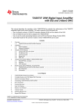
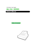
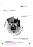
Individual Use Data Stations
Figure 1-1 shows configurations for an analog data station and a digital data
station, both intended for individual use.
1. Analog Voice and Analog Data includes a data station with an endpoint,
such as a data terminal or PC connected via a modem, and an analog
multiline telephone. A GPA supplies the tip/ring (T/R) interface for the
modem. To provide simultaneous voice and data calls, two adjacent station
jacks must be assigned on a 408, 408 GS/LS, or 008 module using a
BR-241-B1 bridging adapter.
2. On- or Off-Premises Analog Data-Only is an endpoint connected via a
modem, Connection to the control unit is through an off-premises telephone
(OPT) jack on a 008 OPT module.
3. Analog Data-Only is an endpoint connected via a modem to a basic station
jack on a 008 OPT or 012 (basic telephone) module in the control unit.
4. Digital Voice and Analog Data is an endpoint connected via a modem and
a Multi-Function Module (MFM) in an MLX telephone connected to the control
unit. The modem converts the digital signal to an analog signal that is sent
through the MFM in the MLX telephone connected to the control unit.
5. Digital Voice and Digital Data is an endpoint connected via an ISDN 7500B
Data Module attached to an MLX telephone. The ISDN 7500B Data Module
supplies the RS-232 interface to the endpoint. The MLX telephone connects
to a station jack on a 008 MLX module.
6. Digital Data-Only is an endpoint connected via an ISDN 7500B Data
Module. Since an MLX telephone is not attached, a 440A4 terminating
resistor must be installed. The data station is connected to a station jack on a
008 MLX module.
Data Communications Components
1-5
Data Communications with This System
RS-232
ADJUCENT ODD/EVEN JACKS
"OTHER" JACK
ANALOG
MULTILINE
TELEPHONE
1.
ANALOG VOICE
& ANALOG DATA
T/R
BR-241-B1
BRIDGING ADAPTER
2 .
TO ON OR OFF-PREMISES
ANALOG
DATA ONLY
3.
ANALOG DATA ONLY
RS-232
T/R
RS-232
T/R
OPT
JACKS
T/R
T/R
RS-232
4.
DIGITAL VOICE
& ANALOG DATA
MLX
TELEPHONE
WITH MFM
RS-232
T/R = TIP/RING
440A4 = TERMINATING RESISTOR
PSU = WP-90110-L1 POWER UNIT, 115 VAC
MLX
TELEPHONE
(can not be
used to dial
data calls)
PSU
Figure 1-1
Individual Use Data Station Configurations
1-6 Data Communications Components
RS-232
5.
DIGITAL VOICE
& DIGITAL DATA
6.
DIGITAL
DATA ONLY
Data Communications with This System
Modem Pools and Data Hunt Groups
See "Data Hunt Group Planning" in
Chapter 3 of this guide.
Figure 1-2 shows analog modems and digital data modules assigned to modem
pools and DHGs so that analog and digital stations can communicate with each
other.
1. Digital to Analog converts digital signals to analog signals so a digital
station can communicate with an inside or outside analog station. Each
modem is assigned to a basic station jack on a 012 or 008 OPT (basic
telephone) module, and each data module is assigned to a 008 MLX module.
2. Analog to Digital converts analog signals to digital signals so an analog
data station can communicate with an inside or outside digital data station.
Each modem is assigned to a basic station jack on a 012 or 008 OPT (basic
telephone) module, and each data module is assigned to a 008 MLX module.
3. Digital to Analog (Outgoing) converts digital signals to analog signals so a
digital data station can communicate with an outside analog station over
outside dedicated lines. These lines are used solely for data
communications. The data module is connected to the control unit using
station jacks on a 008 MLX module.
4. Analog to Digital (Incoming) converts digital signals to analog signals so a
digital data station can communicate with an outside analog station over
outside dedicated lines. These lines are used solely for data
communications. The data module is connected to the control unit using
station jacks on a 008 MLX module.
Note: Since an MLX telephone is not connected, a 440A4 terminating resistor
must be installed.
Data Communications Components
1-7
Data Communications with This System
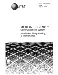
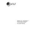
Local Host Computer and LAN Workstations
Figure 1-3 shows how data stations can be assigned to DHGs to provide access
to a local host computer and a workstation on a local area network (LAN).
1. Local Host Computer connects a local host computer via a modem or data
module to the control unit.
The modems and data modules connect to RS-232 ports on the host
computer. Each modem is assigned to a station jack on a 012 or 008 OPT
module and each data module connects to a 008 MLX module station jack.
2. LAN Workstation connects a data terminal or computer (workstation) on the
IAN via modems or data modules to the system. A LAN is a group of
terminals or PCs connected to each other or to a local host.
Figure 1-3 shows how a data station communicates with a local host computer
or another workstation by dialing one extension number. For example, extension
711 could be assigned to the data station DHG, and extension 773 could be
assigned to the modem DHG for communicating with the local host computer.
Extension 774 could be assigned to the data station DHG and extension 775
could be assigned to the modem DHG for communicating with other
workstations on the LAN.
Data Communications Components
1-9
Data Communications with This System
T/R
DHG
T/R
T/R
DHG
T/R
1.
LOCAL HOST
DHG
2.
WORKSTATION
ON LOCAL
AREA
NETWORK
DHG
T/R = TIP/RING
440A4 = TERMINATlNG RESISTOR
PSU = WP-90110-L1 POWER UNIT, 115 VAC
Figure 1-3
Data Stations Connected to Local Host Computer and LAN Workstation
1-10 Data Communications Components
Data Communications with This System
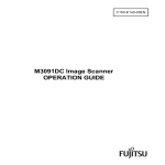
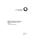
Outside Lines/Trunks
Figure 1-4 shows the types of outside lines/trunks that can be used to make and
receive data calls to outside data stations.
1. GS (ground-start) Iines/trunks are used to place and receive data calls
from an outside analog data station and also provide improved signaling and
a dependable disconnect (for secure toll restriction).
LS (loop-start) Iines/trunks are the standard for home and small
businesses. They are less expensive in some areas but
■
■
they do not protect against “glare." Glare occurs when an outside call is
made at the same time as another call is arriving.
they cannot provide dependable disconnect for toll restriction
The following outside GS/LS lines/trunks can be used for data:
basic lines/trunks
WATS (wide area telecommunications service)
800 service (in-WATS)
foreign exchange (FX)
GS/LS Iines/trunks connect to GS/LS jacks on the system.
See System Reference for detailed
information and programming
requirements for tie trunks.
2. Tie Trunks provide private communications between two systems. Tie trunks
“tie” the two systems together, providing access to all telephones or data
stations on each system.
Tie trunks are usually used for data communication with analog stations
connected to a system at a different location, such as different floors of a
building, different buildings, and different cities or states.
Tie trunks connect to the system on a 400EM module.
See System Reference for detailed
information and programming
requirements for DID trunks.
3. DID (Direct Inward Dial) Trunks allow incoming calls to reach specific
individuals or facilities in the system without the help of a system operator.
DID trunks are available only in the Hybrid/PBX mode.
DID trunks are used to receive calls from outside analog data stations.
Outgoing calls cannot be placed on DID trunks.
DID trunks connect to the system on an 800 DID module.
4. DS1 facility carries digital signals in the Digital Signal 1 (DS1) format.
The DS1 format passes digital data at 1.5444 Mbps by multiplexing twentyfour 64-kbps Digital Signal 0 (DS0) signals and an 8-kbps framing signal.
Even though there is only one physical jack, the 100D module supports up to
twenty-four logical endpoints or ports (one for each channel) for voice and
data calls.
Each DS0 channel in the DS1 signal corresponds to a line/trunk or logical ID.
Data Communications Components
1-11
Data Communications with This System
1. GS/LS
LINES/TRUNKS
DATA CALLS TO
OUTSIDE
ANALOG DATA
STATIONS
GS/LS
JACKS
2. TIE TRUNKS
TIE
TRUNK
JACKS
3. DID TRUNKS
DID
ACK
4. DS1 FACILITIES
DATA CALLS TO
OUTSIDE
DATA STATIONS
PRI FAClLITIES
DS1
JACK
T1 FAClLITIES
DS1
JACK
DATA CALLS TO
OUTSIDE
ANALOG
DATA STATION
Note: T1 Facilities
connected to
this system
cannot support
digital
transmissions.
T/R = TIP/RING
440A4 = TERMINATING RESISTOR
PSU = WP-90110-L1 POWER UNIT, 115 VAC
Figure 1-4
Outside Lines/Trunks
1-12 Data Communications Components
Data Communications with This System
The DS1 provides a digital signal so data calls from a digital station can be
placed to outside digital stations and transmitted at higher speeds (up to
56 kbps).
See System Reference for detailed
information and programming
requirements for DS1 facilities.
A DS1 facility provides either T1 or PRI access.
T1 is the factory setting. Each of the 24 channels can emulate any
combination of E&M tie, LS, or GS lines/trunks. A single 100D module can
replace 24 outside lines/trunks. T1 facilities are used to place and receive
data calls from outside analog data stations. Outside digital data
communications are not supported.
ISDN-PRI is the standard format for ISDN service. Any combination of the
following AT&T Switched Network (ASN) Services provided through an
ISDN-PRI line/trunk can be used:
■
■
■
■
Accunet® switched digital service for 56-kbps and 64-kbps restricted,
and 64-kbps clear circuit-switched data calls
Megacom® WATS service for domestic long-distance outward voice
calls
Megacom® 800 for domestic toll-free voice calls
Software Defined Network (SDN) for voice and circuit-switched data
calls (up to 56 kbps)
The benefits of ISDN-PRI include
Speed. Data calls to outside destinations can be made on the same
B channels used for voice calls if the service allows. Modems and
dedicated, conditioned lines/trunks are not needed.
AT&T’s INFO-2 automatic number identification (ANI) service.
Customers who subscribe to this service can identify the caller on an
incoming call on an ISDN-PRI line/trunk by either telephone number or
billing number.
Note: The availability of the caller identification information may be
limited by local-serving (caller’s) jurisdiction, availability, or central
office equipment.
Dynamic B-channel assignment. An individual B channel can be
removed from service without blocking calls to or from any other B
channels.
Improved toll restriction. Bypassing of toll restriction is limited on
ISDN-PRI lines/trunks.
Reliable indication of far-end disconnect. Blocking of incoming calls is
prevented because a line/trunk is not immediately released; instead
there is a delayed indication of disconnect.
Improved SMDR reports. Call timing for SMDR reports is improved
since calls recorded are closer to the actual billed duration.
Shared use of B channels for Megacom WATS and Megacom 800 on a
call-by-call basis for more efficient use of facilities.
Data Communications Components
1-13
2
Data Communications Hardware
ISDN 7500B Data Modules and modems connect data terminal equipment
(DTE) such as a PC, printer, optical scanner, local host computer, or LAN
workstation to the communications system.
This chapter explains how data modules and modems work, how they connect
to the system, how to configure them, and the features they offer.
ISDN 7500B Data Module
The Integrated Services Digital Network (ISDN) 7500B Data Module connects
digital data terminal equipment to the system via a 008 MLX module on the
system. Unlike a modem, which converts digital data signals to analog signals, a
data module transmits digital data to other digital stations.
The data module provides an RS-232 interface for asynchronous transmission
from DTE at speeds of up to 19.2 kbps. It can also provide a V.35 interface for
synchronous transmission at speeds of up to 64 kbps if you order a separate
board.
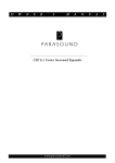
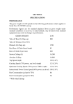
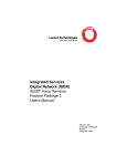
Figure 2-1 shows the following on the lSDN 7500B Data Module’s front panel:
POWER/TEST LED. Lights when power is supplied and flashes when tests
are made.
DATA LED. Flashes when a data call comes in and lights when a call is in
progress; flashes when tests are made.
Display. Shows status information and option settings.
NEXT, BACK, and ENTER buttons. Used to operate the data module and to
adjust the screen’s contrast.
Figure 2-1 also shows the following on the underside of the ISDN 7500B Data
Module’s top cover:
■
DCE/DTE Flip Board. Used to select whether the data module operates with
data terminal equipment connected directly or as part of a modem pool.
ISDN 7500B Data Module
2-1
Data Communications Hardware
DCE/DTE Flip Board
Figure 2-1
ISDN 7500B Data Module Front Panel
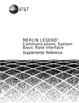
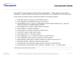
Figure 2-2 shows the following on the data module’s back panel:
PHONE jack. Connects an MLX telephone to the data module.
LINE jack. Connects the data module to the digital station jack on the 008
MLX module.
POWER connector. Connects the data module to the DC power supply,
which connects to an AC outlet.
PORT 1. Connects the data module to a data terminal (such as a PC) or,
when the data module is used in a modem pool, to a modem.
PORT 2. When an enhancement board is installed for synchronous
operation, connects a second data terminal, an automatic calling device
(with an RS-366 interface), or a data terminal with a V.35 interface
(depending on the type of enhancement board you have).
PORT 2
PHONE
LINE
PORT 1
POWER
Female 25-pin EIA
Figure 2-2
2-2
ISDN 7500B Data Module
ISDN 7500B Data Module Back Panel
Data Communications Hardware
Hardware
When you use the ISDN 7500B Data Module with an MLX telephone, one end of
a D8W cord connects to the PHONE jack on the data module and the other end
of the cord connects to the LINE jack on the MLX telephone.
When you use the ISDN 7500B Data Module without an MLX telephone, you
must install a 100-ohm 440A4 terminating resistor adapter (PEC 2709-A59) on
the line near the data module.
Note: You cannot locate the data module more than 80 feet from the telephone.
You can configure the data module as a stand-alone (order a WP-90110-L1
power unit [PEC 21625]) or in a multiple-mount arrangement (order a Z77A data
mounting [PEC 21626]). The multiple-mount arrangement provides a common
power supply for up to eight data modules. Both the power unit and the data
mounting need a 115-VAC power outlet. You must order the power unit and data
mounting separately.
For synchronous operation at speeds of up to 64 kbps, order one of the
following circuit boards:
Multipurpose Enhancement Board. Provides an RS-366 Automatic Calling
Unit (ACU) interface on PORT 2 and converts the RS-232 interface on
PORT 1 on the main circuit board from asynchronous to synchronous. You
must order a V.35 adapter cable separately to operate at data rates of 56
and 64 kbps. Without the adapter cable, data rates are limited to 1200, 2400,
4800, 9600, and 19,200 bps.
■
High-Speed Synchronous Interface Enhancement Board. Provides a V.35
interface at synchronous data rates of 48, 56, or 64 kbps on PORT 2. A V.35
adapter cable that converts the 25-pin male connector on PORT 2 to the
industry-standard 34-pin V.35 interface is included. PORT 1 is not used.
Features
See the Integrated Services Digital
Network (ISDN) 7500 Data Module
User’s Manual for detailed information
on the features available and how they
are used for data calls.
The data module offers both asynchronous and synchronous features:
Asynchronous
Features
■
RS-232 interface
■
asynchronous full-duplex operation
■
data rates of 300, 1200, 2400, 4800, 9600, or 19,200 bps
■
data options set by data terminal equipment
■
data options set without dropping a data call
■
autobaud (also called data metering or speed matching)—adjusts the
transmission speed to match the speed of the data terminal being called
■
auto-adjust—adjusts to the speed and parity of the data terminal equipment
used
ISDN 7500B Data Module 2-3
Data Communications Hardware
■
call setup (dialing) from the keyboard of an ASCII data terminal using the
local command (CMD) mode or AT mode
■
automatic or manual answering of incoming data calls
Synchronous Features with Multipurpose Enhancement Board
RS-232 interface
half- or full-duplex operation using the RS-232 interface at data rates of 1200,
2400, 4800, 9600, and 19,200 using data transport Mode 2
half- or full-duplex operation at 56 kbps with the V.35 interface adapter cable
full-duplex operation at 64 kbps with the V.35 interface adapter cable
automatic answering of incoming data calls
ability to place outgoing data calls manually and select user-programmable
telephone numbers from the data module display on the front panel
RS-366 interface to an automatic calling unit (ACU)
Synchronous Features with High-Speed Synchronous Enhancement
Board
V.35 interface (The adapter cable is provided when you order the board
using PEC 21624.)
full-duplex operation at 48, 56, and 64 kbps
half-duplex operation at 56 kbps only
automatic answering of incoming data calls
ability to place data calls manually and select user-programmable telephone
numbers from the data module display on the front panel
2-4 ISDN 7500B Data Module
Data Communications Hardware
Modems
A modem is used at an analog data station to place or answer data calls.
Modems convert outgoing digital signals from the data terminal into analog
signals for transmission, and convert incoming analog signals to digital signals
for the data terminal.
Hardware
Since you can connect different types of modems to the system, specific
modem hardware is not discussed in this’ book. Modems also provide a variety
of features in addition to the basic features listed below. Modems used in
modem pools, however, must have the following features:
full-duplex operation
support of 10-bit code (start, 8 data bits, stop)
RS-232 asynchronous interface
data rates of 300, 1200, 2400, 4800, and 9600 bps
dual-tone multi-frequency (DTMF) dialing through the RS-232 interface
ability to turn on or maintain the Clear-to-Send indicator when it is ready to
receive ASCII dialing sequences from the data module in response to a
Data-Terminal-Ready signal from the data module
ability to keep the Data-Set-Ready lead on (and not turn it off) during
transition from the interactive dialing mode to the data mode
ability to terminate a data call or dialing sequence when the data module
turns off its Data-Terminal-Ready lead
ability to turn off the Data-Set-Ready or Receive-Line-Signal-Detect lead for a
minimum of 50 ms when hanging up at the termination of a data call
ability to turn on the Ring indicator lead for at least 100 ms in the presence of
an incoming analog call
support of Electronic Industries Association (EIA) signals Cl and CI2 if the
modem is multispeed
AT&T model 2224G (PEC 2224-CEO for stand-alone, PEC 2224-GED for rackmounting arrangement) is recommended for modem pools.
See System Reference for information
on the MFM and GPA.
To use a modem with an MLX telephone, install a Multi-Function Module (MFM)
in the telephone to provide a tip/ring (T/R) interface for the modem. The modem
connects directly to the MFM. You use the data terminal keyboard to dial data
calls and use the telephone dialpad to dial voice calls. Each device operates
independently, and features are assigned to each device independently.
To use a modem with an analog multiline telephone, install a General Purpose
Adapter (GPA) to provide a T/R interface. You use the telephone dialpad to dial
data and voice calls. Features assigned to the telephone are also assigned to
the analog data station.
Modems
2-5
Data Communications Hardware
Features
Analog data stations (those not in a modem pool) in the system offer the
following features, depending on your modem:
dialing of asynchronous data calls from the keyboard when connected to a
basic telephone station jack on a 012 or 008 OPT module or when connected
to an MLX telephone using an MFM
autobaud (also called data metering or speed matching) for adjusting the
speed of transmission to match the speed of the data terminal being called
automatic or manual answering of incoming data calls
self-test and maintenance procedures
ability to set data options for the call on the keyboard and change-the
options without dropping the call
2-6 Modems
Data Communications Hardware
Modem Pools
A modem pool (also called a conversion resource) consists of one or more pairs
of data modules and modems. A modem pool converts data signals from digital
to analog or from analog to digital for communications between digital and
analog data stations.
Modem pools can be
■
Analog to Digital. Converts analog signals to digital signals so that analog
data stations can communicate with inside digital stations or outside digital
ISDN-PRI facilities.
■
Digital to Analog. Converts digital signals to analog signals so that digital
data stations can communicate with inside analog data stations or place data
calls using the regular telephone network.
Modem pools can operate in one direction only—analog-to-digital or digital-toanalog (incoming or outgoing). Dedicated outside analog lines can be
connected directly into analog modems in an analog-to-digital modem pool (and
through a data module to 008 MLX ports on the system).
Hardware
In a modem pool, the modem connects to the control unit via a basic station
jack on a 012 or 008 OPT module. An ISDN 7500B Data Module (PEC 2164BDM) connects to the control unit via a digital station jack on a 008 MLX
module.
In an analog-to-digital modem pool, data calls are placed to outside data
stations through the control unit using system lines (outside ISDN-PRI facilities
connected to the DS1 line/trunk jack on a 100D module in the control unit).
In a digital-to-analog modem pool, data calls are placed to outside data stations
through the control unit using system lines (outside lines/trunks connected to a
line/trunk jack on a 400, 400 GS/LS/TTR, 800, 800 GS/LS, 408, 408 GS/LS, 800
DID, or 400EM module in the control unit).
Since the data module in a modem pool operates without an MLX telephone,
you must install a 100-ohm 440A4 terminating resistor adapter (PEC 2709-A59)
on the line near the data module.
You can configure the ISDN 7500B Data Module as a stand-alone by ordering a
WP-90110-L1 power unit (PEC 21625) or in a multiple-mount arrangement by
ordering a Z77A data mounting (PEC 21626). The Z77A provides a common
power supply for up to eight data modules. Both the power unit and the data
mounting require a 115-VAC power outlet. Neither is provided with the data
module and both must be ordered separately.
Modem Pools
2-7
Data Communications Hardware
Option Settings
See the user manuals provided with the
modem and the lSDN 7500B Data
Module for setting hardware and
software options, and for explanations
of the options.
The options set for a modem and data module in a modem pool differ
depending on whether the modem pool is digital-to-analog or analog-to-digital.
Digital-to-Analog Settings
Data Module Setting
If the modem or Data Module is rack-mounted, you may have to supply or
remove power to a single modem or data module.
To prepare the data module for a digital-to-analog modem pool:
1. Set the DCE/DTE flip board to the DTE position.
2. Use the front panel controls on the data module to get the following option
display.
Table 2-1 Data Module Settings for Digital-to-Analog Modem Pool
Position:
1
2
3
4
5
6
7
8
9
10 11 12 13 14 15 16
L
1
:
3
3
3
0
0
0
b
0
0
1
0
1
1
L
2
:
0
1
1
1
0
0
0
3
1
0
0
0
0
b = blank
L = Line #
Modem Setting
The AT&T model 2224G modem is designed for modem pools. One way to
prepare this modem for operation in a digital-to-analog modem pool is shown
below and may be different depending on your type of modem.
1. Connect a data terminal such as a PC to the modem and plug both the
modem and data terminal into an AC outlet.
2. Use the instructions provided with the modem to set all bit switches to default
positions.
3. Save all bit-switch settings by unplugging the modem from the wall outlet
and plugging it back in.
4. Set the data terminal speed to match the modem’s default speed.
5. The modem is now operating in the AT&T command protocol. Use these
steps to set the default options:
■
Type o d .
■
Press Enter.
6. Set all bit switches according to Table 2-2.
2-8 Modem Pools
Data Communications Hardware
Table 2-2 Modem Option Settings for Digital-to-Analog Modem
Pool Operation
1
2
3
4
5
6
7
8
1
L
R
L
R
R
R
L
L
2
L
R
L
L
L
L
L
L
3
D
D
D
D
U
U
D
D
4
D
D
D
D
D
U
D
D
5
U
D
U
U
U
D
D
D
7
on
on
Bit Number:
Switch
L = left
R = right
U = up
D = down
7. Unplug the modem from the wall outlet; then plug it back in. Set switch 1,
bit 2 to the left to store the switch settings in the modem’s memory. The
modem is now operating in the AT&T command protocol.
8. Enter command mode, set the options, and save the options in protected
memory to prevent loss of settings in case of a power failure:
Analog-to-Digital Settings
■
Type AT and press Enter to enter the local mode.
■
Type AT&D2 and press Enter. Option set: drop call when DTR low.
■
Type AT&C1 and press Enter. Option set: data carrier detect follow call.
■
Type ATS0=1 and press Enter. Option set: Auto Answer.
■
Type ATQ0 and press Enter. Option set: enable result codes (factory
setting).
■
Type AT&W and press Enter to save the options in protected memory
and prevent loss of settings in case of a power failure.
ISDN 7500B Data Module Option Setting
Use the following procedure to prepare the ISDN 7500B Data Module for
operation in an analog-to-digital modem pool:
1. Set the DCE/DTE flip board to the DTE position.
2. Use the front panel controls on the data module to see the following.
Modem Pools
2-9
Data Communications Hardware
Table 2-3 Data Module Settings for Analog-to-Digital Modem Pool
Position:
1
2
3
4
5
6
7
8
9
L
1
:
3
3
3
0
1
0
b
0
0
1
0
1
0
L
2
:
0
1
1
1
0
0
0
3
1
0
0
0
0
10 11 12 13 14 15 16
b = blank
L = Line #
Modem Setting
The AT&T model 2224G modem is designed for modem pools. One way to
prepare this modem for operation in a digital-to-analog modem pool is shown
below and may be different depending on your type of modem:
1. Connect a data terminal such as a PC to the modem and plug both the
modem and data terminal into an AC outlet.
2. Use the instructions provided with the modem to set all bit switches to the
default positions.
3. Save all bit-switch settings by unplugging the modem from the wall outlet
and plugging it back in.
4. Set the data terminal speed to match the modem’s default speed.
5. The modem is now operating in the AT&T command protocol. Use these
steps to set the default software options:
■
Type o d .
■
Press Enter.
6. Set all bit switches according to Table 2-4.
Table 2-4
Bit
Modem Settings for Analog-to-Digital Modem Pool
Number:
1
2
3
4
5
6
7
8
1
L
L
L
R
R
R
L
L
2
L
R
L
L
L
L
L
L
3
D
D
D
D
U
U
D
D
4
D
D
D
D
D
U
D
D
5
U
D
U
U
U
D
D
D
7
on
on
Switch
L = left
R = right
2-10 Modem Pools
U = up
D = down
Data Communications Hardware
7. Unplug the modem from the wall outlet; then plug it back in. Set switch 1,
bit 2, to the left to store the switch settings in the modem’s memory. The
modem is now operating in the AT&T command protocol.
8. Set the options, and save the options into protected memory to prevent loss
of settings in case of a power failure:
■
Type AT and press Enter to enter the local mode.
■
Type AT&D2 and press Enter. Option set: drop call when DTR low.
■
Type AT&C1 and press Enter. Option set: data carrier detect follow call.
■
Type ATS0=1 and press Enter. Option set: Auto Answer.
■
Type ATQ1 and press Enter. Option set: disable result codes.
■
Type AT&W and press Enter to write options to protected memory
Modem Pools 2-11
Data Communications Hardware
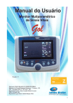
Hardware Decision Flowcharts
The following flowcharts show hardware required for specific data
communications uses. Figure 2-3 is for asynchronous transmission and
Figure 2-4 is for synchronous transmission.
2-12 Hardware Decision Flowcharts
Data Communications Hardware
NO
Is the
equipment used
in a modem
pool?
YES
Are the
modems and
data modules
stand-alone?
N O
DIGITAL
Is the
data station
digital or
analog?
ANALOG
ORDER:
- 7500B Data Module
PEC 2164-BDM
- Z77A data Mounting
PEC 21626
- 440A4 terminating
resistor adapter
PEC 2709-A59
- 2224G Modem
PEC 2224-GED
- Malti Moount for
2224G Modem
PEC 22248
Does the
analog data station
include a
telephone?
N O
ORDER:
- Modem
(ssee sales manual)
NO
Is the
data module
stand-alone?
ORDER:
. 7500B Data Module
PEC 2164-BDM
- Z77A data mounting
PEC 21626
- 440A4 terminating
resistor adapter
PEC 2709-A59
Figure 2-3
Does the
digital data
station include an
MLX telephone?
DIGITAL/ISDN
MULTILINE
ANALOG
MULTILINE
Type
of
telephone?
ORDER:
- GPA
PEC 2301-GPA
- Modem
(see sales manual)
YES
YES
ORDER:
- 7500B Data Module
PEC 2164-BDM
- WP-90110-L1
power unit
PEC 21625
- 440A4 terminating
resistor adapter
PEC 2709-A59
ORDER:
- 7500B Data Module
PEC 2164-BDM
- WP-90110 L1 Power Unit
PEC 21625
- 440A4 terminating
resistor adapter
PEC 2709-A59
- 2224G Modems
PEC 2224-CEO
YES
ORDER:
- MFM
PEC 3156-MPM
- Modem
(see sales manual)
NO
YES
N O
ORDER:
- 7500B Data Module
PEC 2164-BDM
- Z77A data mounting
PEC 21626
Is the
data module
stand-alone?
YES
ORDER:
- 7500B Data Module
PEC 2164-BDM
- WP-90110-L1
power unit
PEC 21625
Asynchronous Hardware Decision Flowchart
Hardware Decision Flowcharts
2-13
Data Communications
Hardware
Do data rate
requirements
include low speeds
(1200, 2400. 4800,
9600, 19, 200 bps)?
NO
Does data
station include an
MLX telephone?
NO
YES
Is
data module
stand-alone?
ORDER:
- 7500B Data Module
PEC 2164-BDM
- Z77A data mounting
PEC 21626
- High speed
synchronous
enhancement board
PEC 21624
Is
data module
stand-alone?
NO
YES
ORDER:
- 7500B Data Module
PEC 2164-BDM
- Z77A data mountiong
PEC 21626
- 440A4 terminating
resistor adapter
PEC 2709-A59
- Multipurpose
enhancement board
PEC 21623
Figure 2-4
NO
Is
data module
stand-alone?
YES
Does data
station include an
MLX telephone?
Is
data module
stand-alone?
NO
Does data
station include an
MLX tekephone?
NO
NO
NO
YES
ORDER:
- 7500B Data Module
PEC 2164-BDM
- WP-90110-L1
poewr unit
PEC 21626
- High speed
synchronous
enhancement board
PEC 21624
ORDER:
- 7500B Date Module
PEC 2164-BDM
- WP-90110-L1
power unit
PEC 21626
- 440A4 terminating
resistor adapter
PEC 2709-A59
- High speed
synchronous
enhancement board
PEC 21624
ORDER:
- 7500B Date Module
PEC 2164-BDM
- Z77A data mounting
PEC 21626
- 440A4 terminating
resistor adapter
PEC 2709-A59
- High speed
synchronous
enhancement board
PEC 21624
Do data rate
requirements
include high speeds
(up t0 64 Kbps)?
NO
NO
NO
YES
Is
data module
stand-alone?
YES
YES
ORDER:
- 7500B Data Module
PEC 2164-BDM
- WP-90110-L1
power unit
PEC 21626
- 440 A4 terminating
resistor adapter
PEC 2709-A59
- Multipurpose
enhancement board
PEC 21623
ORDER:
- 7500B Data Module
PEC 2164-BDM
- Z77A data mounting
PEC 21626
- Muttipurpose
enhancement board
PEC 21623
Synchronous Hardware Decision Flowchart
2-14 Hardware Decision Flowcharts
YES
Is
data module
stand-alone?
YES
YES
YES
ORDER:
- 7500B Data Module
PEC 2164-BDM
- Z77A data mounting
PEC 21626
- Multipurpose
enhancement board
PEC 21623
- V.35 adapter cable
(Order from general
trade supplier of data
products)
ORDER:
- 7500B Data Module
PEC 2164-BDM
- WP-90110-L1
power unit
PEC 21626
- 440A4 terminating
resistor adapter
PEC 2709-A59
- Multipurpose
enhancement board
PEC 21623
- V.35 adapter cable
(Order from generaI
trade supplier of data
products)
ORDER:
- 7500B Data Module
PEC 2164-BDM
- WP-90110-L1
power unit
PEC 21626
- Multipurpose
enhancement board
PEC 21623
ORDER:
- 7500B Data Module
PEC 2164-BDM
- WP-90110-L1
power unit
PEC 21626
- Multipurpose
enhancement board
PEC 21623
- V.35 adapter cable
(Order from general
trade supplier of date
products)
ORDER:
- 7400B Data Module
PEC 2164-BDM
- Z77A data mounting
PEC 21626
_ 440A4 terminating
resistor adapter
PEC 2709-A59
- Multipurpose
enhancement board
PEC 21623
- V.35 adapter cable
(Order from general
trade supplier of data
products)
3
Planning
Planning is the key to making the most of the data features offered by the
communications system. This chapter tells you how to plan analog and digital
data stations.
Planning Overview
By using System Planning (Key or PBX), you should have already reserved the
following:
■
line/trunk jacks for outside lines/trunks
■
station jacks for voice telephone users
■
station jacks for either:
■
■
analog multiline telephones with an analog data station connected to a
General Purpose Adapter (GPA)
digital/lSDN (MLX) telephones with either an analog data station
connected via an MFM or a digital data station connected via an ISDN
7500B Data Module.
Note: Features and lines for analog data stations connected to an analog
multiline telephone via a GPA cannot be assigned independently of the
telephone. This includes reserving two consecutive analog station jacks on the
control unit for the Simultaneous Voice and Data feature. Planning for these
types of analog data stations and the Simultaneous Voice and Data feature is
covered in System Planning (Key or PBX) and is not included in this book.
On a new system, you can either plan and program voice communications
equipment first and data communications equipment second, or plan and
program voice and data equipment concurrently.
Planning Overview
3-1
Planning
Forms
Whether you are planning data options for a new system or modifying an
existing system, record your decisions on the appropriate data forms shown in
Table 3-1. Duplicate the master forms in Appendix A and work on the copies.
Use the Key or PBX system forms listed in Table 3-2, as needed.
When you finish planning, see Chapter 4, “System Programming," to program
these data options.
Table 3-1 Data Planning Forms
To Plan New or Modify Existing
Use These Forms
Modem pools
1a, Modem Pool—Analog to Digital
1b, Modem Pool—Digital to Analog
Note: To plan or modify digital-to-analog modem pools
using dedicated outside lines, you may need telephone
circuits from your local telephone company.
Line assignments
2a, Analog Data Station
2b, Digital Data Station
Feature assignments
2a, Analog Data Station
2b, Digital Data Station
Data hunt groups
3, Data Hunt Groups
3-2 Forms
Planning
Table 3-2 Key or PBX System Forms
T O Use as
Reference
To Make
Entries
2a, System Numbering—Station Jacks
(for all configurations)
✓
✓
2a, System Numbering—Station Jacks
✓
✓
2a, System Numbering—Station Jacks
2b, System Numbering—Digital/lSDN Station
Adjuncts
2c, System Numbering—Trunk/tine Jacks
3b, Outside Trunks—Pools (Hybrid/PBX only)
✓
✓
To Plan
You Need Key or PBX System Form
■
Station jack connections
analog data stations
■ digital data stations
■ local host computer connections
■ LAN workstation access
connections
Modem pools
Note: Modem pool planning
includes station jack identification
and determining pool type—analogto-digital or digital-to-analog.
Line assignments (Key and
Hybrid/PBX)
Note: Behind Switch is not included
in these instructions.
Feature assignment
2a, System Numbering—Station Jacks
2b, System Numbering—Digital/lSDN Station
Adjuncts
4b, Digital/lSDN (MLX) Telephone
—reverse side, MFM Adjunct
5b, Direct-Line Console (DLC) Digital/lSDN
—reverse side, MFM Adjunct
✓
✓
✓
✓
✓
✓
These features also need
pool dial-out code (Hybrid/PBX
only)
3b, Outside Trunks—Pools
✓
ARS Facility Restriction
(Hybrid/PBX only)
9b, Automatic Route Selection Tables
9c, ARS Default and Special Numbers Table
✓
✓
data hunt groups
2c,
2d,
3b,
6e,
System Numbering—Trunk/Line Jacks
System Numbering—Special Renumbers
Outside Trunks—Pools
Group Calling
✓
✓
✓
✓
Forms 3-3
Planning
Station Jacks
To plan how data equipment connects to station jacks on the control unit:
1. Review System Form 2a, on which you entered codes (A for analog, D for
digital, and B for basic telephone) and find the telephone type and the user,
location, or function for each data station to be connected. Table 3-3 shows
station jack types, corresponding module types, and the equipment that can
be connected.
Note: Plan the connections for analog data, digital data, and local host
computer communications stations according to the following instructions
only if the system includes that station type.
2. Add the station jack assignments to System Form 2a using the “Planning
Form Instructions" in the shaded boxes.
Table 3-3 Station Jack Types
Station
Jack
Type
Analog Data Stations
Module
Type
Connects
Analog
008
408
408 GS/LS
Analog multiline telephones (including
telephones with an analog data station
connected through a GPA)
Digital
008 MLX
MLX telephones (including
telephones with an analog data station
connected through an MFM)
Digital data stations connected through
ISDN 7500B Data Modules
Basic
Telephone
012
T/R equipment:
Single-line telephones
Adjuncts, such as answering or fax
machines
Analog data stations (using modems)
008 OPT
Tip/ring equipment in another building or off
premises
An analog data station consists of a data terminal connected to the control unit
using an internal or external modem. This station does not include a telephone.
Assign a basic telephone station jack on a 012 or 008 OPT module; either an onor off-premises station can be connected to a 008 OPT module.
3-4 Station Jacks
Planning
See System Planning (Key or PBX) for
instructions for reassigning station
extension numbers. (The same
instructions are used for data as for
voice stations.)
Planning Form Instructions
Record the station jack assignments for analog data stations on System
Form 2a, System Numbering—Station Jacks:
1. In the "Jack Type" column, make sure there is a "B" next to the number for
each basic station jack.
2. In the "Person, Location, or Function" column, write "modem," then identify
each analog data station by person, location, or function.
Digital Data Stations
A digital data station consists of a PC or a data terminal connected to a data
module. This station does not include a telephone.
Although only one logical ID is assigned to each digital station jack, the system
automatically assigns two extension numbers: the extension number shown on
Form 2a is assigned to an MLX telephone connected to the digital station jack,
and a second extension number is assigned to each jack. The second extension
number is reserved for an adjunct such as an analog data station connected to
the MLX telephone through an MFM or a digital data station connected through
a data module and data terminal. Both extension numbers are automatically.
assigned whether or not the station includes an MFM or ISDN 7500B Data
Module. Calls can be placed to both extension numbers independently. Note
that an MLX station cannot have both a data module and an MFM. The digital
data station uses only the adjunct extension.
Each digital data station connects to a digital station jack on a 008 MLX module.
See System Planning (Key or PBX) for
instructions for reassigning station
extension numbers. (The same
instructions are used for data as for
voice stations.)
Planning Form Instructions
Record the station jack assignments for digital data stations on System
Form 2a, System Numbering—Station Jacks:
1. In the "Jack Type" column, make sure there is a "D" next to the number for
each digital station jack.
2. In the "Person, Location, or Function" column, write "ISDN 7500B Data
Module" and identify each digital data station by person, location, or
function.
3. Fill in System Form 2b with the logical ID and the extension number of the
ISDN 7500B Data Module.
Local Host Computer Data
Stations
See configuration 1 on Figure 1-3 in this
guide.
A local host computer data station consists of a local host computer (sometimes
called a "mainframe” computer), a data terminal, and a data module. Digital
signals from the data station are converted by the data module to RS-232 data
signals (and vice versa) so that the host computer can receive the signals.
Modems convert digital data signals to analog signals (and vice versa).
Station Jacks
3-5
Planning
Assign each data module used for access to a host computer to a digital station
jack on a 008 MLX module and each modem to a basic telephone station jack
on a 012 or a 008 OPT module. Users access the computer by placing a data
call to the extension number for either a data module or modem assigned for
communications with the local host computer.
See "Data Hunt Groups” in this chapter.
If you have a limited number of data modules or modems to share among many
users, assign some or all of the modems or data modules to a data hunt group.
In this way, users can access all the conversion resources in the data hunt
group by dialing one extension number.
For example, analog data station users could dial extension 771 to place a data
call to the local host computer using a modem assigned to the data hunt group
for modems. Similarly, digital station users could dial extension 772 to place a
call to the local host computer using a data module in the data hunt group for
data modules.
Planning Form Instructions
Record the station jack assignments for local host computer access stations
on System Form 2a, System Numbering—Station Jacks:
1. In the "Jack Type" column, make sure there is a "D" next to the number for
each digital station jack used to connect an ISDN 7599B Data Module.
2. In the "Person, Location, or Function" column, write "ISDN 7500B—host."
3. In the "Jack Type" column, make sure there is a "B" next to the number for
each basic telephone station jack you plan to use to connect a modem.
4.
In the "Person, Location, or Function" column, write "modem—host."
LAN Workstations
Local Area Network (IAN) workstations are PCs connected together to share
resources.
See configuration 2 in Figure 1-3 in this
guide for information on connections.
Assign each data module used for access to a LAN workstation to a digital jack
on a 008 MLX module. Each modem must be connected to a basic telephone
station jack on a 012 or 008 OPT module.
To access the workstation, users place a data call to the extension number
resewed for either an ISDN 7500B Data Module or modem.
See "Data Hunt Groups" in this chapter.
If you have a limited number of ISDN 7500B Data Modules or modems that must
be shared by many users, you can assign some or all of the modems or data
modules to a data hunt group. In this way, users can access all the conversion
resources in the data hunt group by dialing a single extension number.
For example, an analog data station user could dial extension 773 to place a
data call to the workstation on the LAN using a modem assigned to the data
hunt group for modems. Similarly, a digital station user could dial extension 774
to place a call to the workstation on the LAN using an ISDN 7500B in the data
hunt group for 7500Bs.
3-6 Station Jacks
Planning
Planning Form Instructions
Record the station jack asignments for access to a workstation on a LAN on
System Form 2a, System Numbering—Station Jacks:
1. In the "Jack Type" column, make sure there is a "D" next to the number for
each digital station jack you plan to use to connect an ISDN 7500B Data
Module.
2. In the "Person, Location, or Function" column, write "ISDN 7500B—LAN."
3. In the "Jack Type" column, make sure there is a "B" next to the number for
each basic telephone station jack used to connect a modem.
4. In the "Person, Location, or Function" column, write "modem—LAN."
See System Planning (Key or PBX),
Chapter 2, for details on system
renumbering.
Note: System Planning (Key or PBX) describes how to reassign station
extension numbers, The same considerations apply to data stations as those
that apply to voice stations.
Station Jacks
3-7
Planning
Modem Pools
See Chapter 1 for information about
connections.
A modem pool consists of one or more pairs of data modules and modems.
Modem pools convert digital data signals to analog data signals or convert
analog data signals to digital signals and are called “conversion resources.”
A modem pool allows data communications between digital data stations and
analog data stations.
An analog-to-digital modem pool is used to call digital data stations from analog
stations. A digital-to-analog modem pool is used to call analog data stations
from digital stations.
A modem pool can use either system lines (shown in Figure 3-1) or dedicated
outside lines (shown in Figure 3-2) and can be either analog to digital or digital
to analog.
Modem pools using dedicated outside lines are useful when
Modem Pools Using System
Lines
■
many data calls are made and you want to be sure data lines are kept
separate from outside system lines used for voice calls
■
your business uses specialized outside lines (such as private circuits for
high-speed transmission) for data communications
Figure 3-1 shows modem pools using system lines. Calls to and from outside
data stations are placed through outside lines connected to the system. These
lines can be reserved for members of a modem pool, or they can be the same
lines that are used for voice communications.
DHG {
012 BASIC
TELEPHONE
STATION
JACKS
DHG {
008 MLX
STATION
JACKS
Figure 3-1
3-8 Modem Pools
440A4 = TERMINATING RESISTOR
PSU = WP-90110-L1 POWER UNIT, 115 VAC
Modem Pools Using System Lines
Planning
For a modem pool using system lines, assign one digital station jack for each
data module and one basic station jack for each modem.
Planning Form Instructions
Record the station jack assignments for modem pool equipment on System
Form 2a, System Numbering—Station Jacks:
1. In the "Jack Type" column, make sure there is a "D" next to the number for
each digital station jack used to connect an ISDN 7500B Data Module.
2. In the "Person, Location, or Function" column, write "ISDN 7500B—
modem pool."
3. In the "Jack Type" column, make sure there is a "B" next to the number for
each basic telephone station jack you plan to use to connect a modem.
4. In the "Person, Location, or Function" column, write "modem—pool."
See System Planning (Key or PBX),
Chapter 2, for details on system
renumbering.
Note: System Planning (Key or PBX) describes how to reassign station
extension numbers. The same considerations apply to data stations as those
that apply to voice stations.
Modem Pools on Dedicated
Lines
To dedicate an outside line exclusively for data communications, you can
bypass the control unit and connect the outside line directly to a modem in a
modem pool. The line is then dedicated for use with that modem pool pair only.
DEDICATED
OUTSIDE
LINES
DHG {
008 MLX
STATION
JACKS
DIGITAL TO ANALOG
DEDICATED
OUTSIDE
LINES
ANALOG TO DIGITAL
44GA4 = TERMINATING RESISTOR
PSU = WP-90110-L1 POWER UNIT, 115 VAC
Figure 3-2
Modem Pools on Dedicated Outside Lines
Modem pools on dedicated lines require only one digital station jack for each
ISDN 7500B Data Module.
Note: Data calls placed using modem pools on dedicated outside lines bypass
the control unit and are not reported by Station Message Detail Recording
(SMDR).
Modem Pools
3-9
Planning
See System Planning (Key or PBX),
Chapter 2, for details on system
renumbering and planning form
instructions.
Planning Form Instructions
Record the station jack assignments for modem pools on dedicated outside
lines on System Form 2a, System Numbering—Station Jacks:
1. In the "Jack Type" column, make sure there is a "D" next to the number for
each digital station jack used to connect an ISDN 7500B Data Module.
2. In the "Person, Location, or Function" column, write "ISDN 7500B—
modem pool dedicated."
Analog-to-Digital
Pool
Modem
To create an analog-to-digital modem pool, choose a modem and a data
module to be paired and the number of pairs you want in the modem pool.
When modems and ISDN 7500B Data Modules are connected to station jacks,
an extension number is automatically assigned to each. To create an analog-todigital modem pool, if you have only one modem pair in the pool, publish the
extension number assigned to the modem. If you have more than one pair and
the modems are assigned to a data hunt group, publish the extension for the
data hunt group.
See “Data Hunt Groups" in this chapter.
If you have more than one modem and data module pair (member) in your
modem pool, use a data hunt group to distribute incoming calls uniformly
among members in the group. A data hunt group can include up to 20
members.
Do not assign system lines and dedicated outside lines in the same modem
pool.
Planning Form Instructions
The logical ID and extension numbers for the modems and data modules
assigned to each analog-to-digital modem pool are listed on System
Form 2a, System Numbering—Station Jacks.
Record the analog-to-digital modem pools on Data Form 1a, Modem Pool
—Analog to Digital.
Note: Data Form 1a provides planning space for 4 modem pools. If you are
planning more than 4 modem pools, make copies of Data Form 1a.
1.
Number the modem pools consecutively—starting with 1. Write the
number in the "Modem Pool Number" space at the top of each modem
pool block.
2. If you have more than one pair and members will be grouped in a data
hunt group, check the "Yes" box. You will enter the extension number
when you create the data hunt group.
3. In the "Modem" column, write the logical ID and extension number of each
modem in the modem pool. On the same line, in the "Data Module"
column, write the logical ID and extension number of the ISDN 7500B
Data Module you want paired with the modem in the first column.
3-10 Modem Pools
Planning
Digital-to-Analog
Pool
Modem
To create a digital-to-analog modem pool, choose a data module and modem to
be paired and choose the number of pairs you want in the modem pool.
When modems and ISDN 7500B Data Modules are connected to station jacks,
an extension number is automatically assigned to each. To create a digital-toanalog modem pool, if you have only one pair in the pool, publish the extension
number assigned to the ISDN 7500B. If you have more than one pair and the
7500Bs are assigned to a data hunt group, publish the extension for the data
hunt group.
Do not assign system lines and dedicated outside lines in the same modem
pool.
See "Data Hunt Groups" in this chapter.
If you have more than one modem and data module pair (member) in your
modem pool, use a data hunt group to distribute incoming calls uniformly
among members in the group. A data hunt group can include up to 20
members.
Planning Form Instructions
The logical ID and exteinsion numbers for the modems and data modules
addigned to each digital-to-analog modem pool are listed on System
Form 2a, System Numbering—Station Jacks.
Record digital-to-analog modem pools on Data Form 1b, Modem Pool—
Digital to Analog.
Note: Data Form 1b provides planning space for 4 modem pools. If you are
planning more than 4 modem pools, make copies of Data Form 1b.
If the modem pool uses dedicated outside lines, get the telephone number of
the outside lines from your local telephone company.
1. Number the modem pools consecutively—starting with 1. Write the
number in the "Modem Pool Number" space at the top of each modem
pool block.
2. If you have more than one pair and members will be grouped in a data
hunt group, check the "Yes" box. You will enter the extension number
when you create the data hunt group.
3. If the modem is connected to the control unit, write the logical ID and
extension number of each ISDN 7500B Data Module in the modem pool in
the "Data Module" column. On the same line, in the "Modem column, write
the logical ID and extension number of the modem you want paired with
the data module in the first column.
If the modem is connected to a dedicated outside line, leave the "Logical
ID" space blank and write the telephone number in the "Extension"
column. Be sure not to mix dedicated outside line connections with
control unit connections.
Modem Pools 3-11
Planning
Assigning Lines to Data Stations
Decide on the types of line buttons that are assigned to the data terminal portion
of each digital or analog data station and to each modem and ISDN 7500B Data
Module.
This includes
■
analog data stations connected through MFMs to MLX telephones
■
digital data stations that include a telephone
■
analog data stations
■
digital data stations
Note: Lines cannot be independently assigned to analog data stations
connected to analog multiline telephones using a General Purpose Adapter
(GPA). The line assignment for the telephone also includes the analog data
station; therefore, these instructions are not used for these types of data
stations.
Planning Form Instructions
For analog data stations that are connected to an MLX telephone using an
MFM, use the reverse side of Key or PBX System Form 4b—Digital/ISDN
(MLX) Telephone, and Key or PBX System Form 5b—Direct-Line
Console (DLS)—Digital/ISDN. You should have already filled out
preliminary information on these forms when you planned voice communications. The lines for the MLX telephone have already been assigned.
There are two different forms for data stations:
■
Data Form 2a is for analog data stations, for modems included in modem
pools, for modems used to communicate with the local host computer, or
for modems used to communicate with a workstation on a LAN.
■
Data Form 2b is for digital data stations and for ISDN 7500B Data
Modules included in modem pools. Data modules used to communicate
with the local host computer, or Data Modules used to communicate with
a workstation on a LAN.
Make enough copies of each form so that you can complete one form for
each piece of data equipment.
Locate System Form 2a, System Numbering—Station Jacks and use it to
fill in the identification information for each data station.
3-12 Assigning Lines to Data Stations
Planning
Planning Form Instructions Continued
Record the information on the appropriate Data Form (2a or 2b) for each
data station and for each modem and ISDN 7500B Data Module included in
a modem pool or used to communicate with a local host computer or with a
workstation on a LAN:
1. In the "Logical ID" space write the logical ID for each station.
2. In the "Extension No." space, write the extension number for each station.
3. In the "Person or Location" space, write the name of the person or the
location of the data equipment.
4. Under the "Data Station Use" heading, check the "Individual use," "local
host computer," or "LAN workstation" box to indicate the use for the data
station.
Each analog or digital data station (including an analog data station connected
to an MLX telephone via an MFM) and each modem or ISDN 7500B Data
Module pair is treated by the system as a multibutton telephone with 34 buttons.
When you choose the mode of operation (Key, Behind Switch, or Hybrid/PBX),
Intercom or System Access buttons are automatically assigned to every station
connected to the control unit. However, you can customize the system by
changing the factory-set assignments and reassigning line buttons. The number
and types of buttons assigned depends on the mode chosen and the type of
station jack you are using.
Assigning Lines in
Hybrid/PBX Mode
The line buttons you can assign to data stations are
System Access Ring— used to make and receive inside and outside data
calls. To make outside calls, the user selects an outside trunk by dialing
either the code for Automatic Route Selection (ARS) or the dial-out code for
the trunk pool. Users at digital data stations can also dial the trunk number
(801-880) to select an outside trunk.
System Access Originate Only— used only to make inside and outside
calls. Calls are not received on this button so that the data user always has a
line available to make data calls. To make outside calls, the user selects an
outside trunk by dialing either the code for ARS or the dial-out code for a
trunk pool. Users at digital data stations can also dial the trunk number
(801-880) to select an outside trunk.
■
Personal Line— used to make and receive outside data calls from a data
station on a specific outside trunk. A personal line is an outside trunk
assigned to a line button on one or more data or voice stations. The outside
trunk cannot be a member of a trunk pool. To dedicate an outside trunk for
data calls and have the calls automatically answered at a data station, do not
assign the same outside trunk to both data stations and telephones because
modems answer voice calls as data calls.
On analog data stations, the personal line can be used to receive incoming
calls. You can use the personal line for outgoing calls by selecting the line
button on the analog multiline telephone, dialing on the analog multiline
telephone, and then activating the modem connected through a GPA.
Assigning Lines to Data Stations 3-13
Planning
On digital stations, the personal line can be used to make and receive
outside data calls. For an outgoing call, dial the trunk number (801-880) to
select the trunk.
To allow the user at a digital station access to the digital network for making
and receiving calls to outside digital stations, assign ISDN-PRI trunks as
personal lines. If ISDN-PRI trunks are not available, the digital data station
user can make calls over the regular analog telephone network only by using
a digital-to-analog modem pool.
Notes:
■
■
■
You must use ISDN-PRI facilities with Accunet Switched Digital Data
service for digital stations.
ISDN-PRI trunks can also be used for analog data and voice calls and
can be assigned to telephones to allow the voice user to make and
receive voice calls using these types of facilities.
Pool— used when you want the data station to make and receive outside
data calls on a specific trunk pool (for example, a pool with ISDN-PRI
channels) without dialing a dial-out code. The Pool button is used to make
and receive only outside calls. To make an outside call, the data station user
selects the pool button and dials the telephone number.
Note: Do not assign System Access Voice buttons for data stations.
The following line button assignments are factory set for Hybrid/PBX mode and
are prerecorded on the "Button Diagram" on Data Forms 2a and 2b:
One System Access Originate Only button and two System Access Ring
buttons are assigned to all analog data equipment connected to a 012 or
008 OPT module.
One System Access Originate Only button and one System Access Ring
button is assigned to all data equipment connected to a digital station jack
on a 008 MLX module.
The factory settings can be changed; however, the settings should be adequate
to meet most user needs since System Access lines can be used to make both
inside and outside data calls. Each data station must have at least one System
Access button.
If you want a data station (digital only) to make and receive outside data calls on
a specific outside trunk, assign a Personal Line button. If you want the data
station to make and receive outside calls on a specific trunk pool, assign a Pool
button.
To allow users outside the system access to the modem pool, assign outside
trunks to the data hunt group that is assigned to the modem pool (you will
assign trunks to modem pools later). If a data hunt group is not assigned to the
modem pool, you must assign personal lines or pods to the modem for analogto-digital modem pools or to the ISDN 7500B Data Module for digital-to-analog
modem pools.
3-14 Assigning Lines to Data Stations
Planning
To dedicate a specific line or pool to receive outside data calls, assign a
personal line or pool to a data station, modem pool, or data hunt group that is
assigned to a modem pool.
To dedicate specific trunks for use in data communications only (such as
Primary Rate Interface channels or other special data lines), consider grouping
those trunks in a pool. Use the instructions on pools in Chapter 3 of PBX System
Planning.
If the system uses Automatic Route Selection, follow the instructions on ARS in
Chapter 4 of PBX System Planning to specify routes for outgoing data calls.
To restrict non-data users from dial access to data trunk pools, use the “Pool
Dial-Out Code" instructions in this chapter.
Planning Form Instructions
Locate System Form 2c, System Numbering—Trunk/Line Jacks and PBX
System Form 3b, Outside Trunks—Pools.
Record your decisions for each data station on the Hybrid/PBX Mode "Button
Diagram" or Data Form 2a or 2b.
1. If you want to assign personal lines to the data station, write "Personal
Line" and the telephone number (form System Form 2c) of the outside line
on the appropriate button. For digital stations, include the trunk number.
2. If you want to assign a pool to the data station, write "Pool" and the pool's
extension number (from system Form 3b) on the appropriate button.
Note: On
calls, you
automatic
office dial
Assigning Lines in Key
Mode
analog data stations where the user does not need to make internal
can assign only personal lines or pools; the user will get a CO line by
line selection when going off-hook. This will automatically get central
tone.
There are two kinds of line buttons you can assign to data stations used to make
and receive data calls:
■
Intercom Ring — used to make and receive inside data calls only.
■
Outside Line — used to make and receive outside data calls on a specific
outside trunk. An outside line can be assigned to a line button on one or
more data or voice stations. To dedicate an outside line for data calls and
have the calls automatically answered at a data station, do not assign the
same outside line to data stations and to telephones because modems
answer voice calls as data calls.
For digital stations, the outside line can be used to make and receive outside
data calls. For an outgoing call, dial the line number (801-880) to select the
Iine.
Assigning Lines to Data Stations 3-15
Planning
To allow the user at a digital station access to the digital network for making
and receiving calls to outside digital stations, assign ISDN-PRI lines to digital
stations. If ISDN-PRI lines (with Accunet Switched Digital Data Services) are
not available, the digital data station user can make calls over the regular
analog telephone network only by using a digital-to-analog modem pool.
Note: ISDN-PRI lines can also be used for analog data and voice calls and
can be assigned to telephones to allow the voice user to make and receive
voice calls using these types of facilities. You must use ISDN-PRI trunks with
Accunet Switched Digital Data Services for digital data stations.
The following line button assignments are factory set for Key mode and are
prerecorded on the “Button Diagram” on Data Forms 2a and 2b:
■
Two Intercom Ring buttons are assigned to all data equipment connected to
a 012 or 008 OPT module.
■
Two Intercom Ring buttons are assigned to all equipment connected to a
digital station jack on a 008 MLX module.
The factory settings can be changed; however, at least one Intercom button
must be assigned to each data station. To allow the user to make and receive
outside data calls, you must assign outside lines to the data station.
To allow users outside the system access to your modem pool, you can assign
outside lines to the data hunt group that is assigned to the modem pool (you will
assign lines to modem pools later). If a data hunt group is not assigned to the
modem pool, you must assign outside lines to the modem for analog-to-digital
modem pools or to the ISDN 7500B Data Module for digital-to-analog modem
pools.
To dedicate a specific line to receive outside data calls, assign an outside line to
a data station, modem pool, data hunt group, LAN, or local host.
See Chapter 2, “Features," of System
Reference for details on Idle Line
Preference.
On a digital or analog station the user selects an outside line by dialing the Idle
Line Preference code (usually 9) on an Intercom button. On a digital data station
the user can also select lines assigned to the station by dialing the line number
(801-880) assigned to that outside line.
It is extremely important that the factory-set Idle Line Preference (the line
to which the user is automatically connected when going off-hook) not be
changed. (The user must be connected to an intercom line to activate
features such as Privacy or to select an available outside line by dialing the
Idle Line Preference coda.)
Planning Form Instructions
Locate System Form 2c, System Numbering—Trunk/Line Jacks.
Record your decisions for each data station on the Key Mode "Button
Diagram" of Data Form 2a or 2b. If you want to assign outside lines to the
data station, write the telephone number (from System Form 2c) of the
outside line on the appropriate button. For digital stations, include the line
number.
3-16 Assigning Lines to Data Stations
Planning
Assigning Features to Data Stations
This section describes how to assign features to each digital or analog data
station and to each modem and ISDN 7500B Data Module pair. This includes
analog data stations connected to an MLX telephone using an MFM or digital
data stations that include a telephone and analog and digital data stations (data
stations that do not include a telephone).
Note: Features cannot be independently assigned to analog data stations
connected to analog multiline telephones using a General Purpose Adapter
(GPA). The feature assignment for the telephone also includes the analog data
station; therefore, the following planning instructions are not used for these
types of data stations.
Assign optional features to data stations. The features are
Voice Announce, Call Waiting, and Automatic Callback
Pool Dial-Out Code (Hybrid/PBX systems only)
Call Restrictions
Forced Account Code Entry
Ringing Options
ARS Facility Restriction Level
System Speed Dial
Record your optional features on Data Form 2a, Analog Data Station and
Data Form 2b, Digital Data Station, the reverse of Key or PBX System
Form 4b, Digital/ISDN (MLX) Telephones, and the reverse of Key or PBX
System Form 5b, Direct-Line Console (DLC)—Digital/ISDN.
Notes:
Voice Announce, Call
Waiting, and Automatic
Callback
■
The System Speed Dial feature is programmed system wide for both voice
and data stations, Follow the instructions in System Planning (Key or PBX) to
assign System Speed Dial codes to data station users.
■
All members of a modem pool should have the same feature assignment.
For each digital or analog data station and each modem and ISDN 7500B Data
Module pair, the following features must be disabled:
■
Voice
Announce
■
Call
■
Automatic
Waiting
Callback
Assigning Features to Data Stations
3-17
Planning
Pool Dial-Out Code
Use these instructions only if the system is operating in the Hybrid/PBX
mode.
When a data station is first connected, the user can access any trunk pool by
dialing the dial-out code assigned to the pool. However, you can restrict data
stations from using one or more trunk pools.
The pool dial-out code restriction places data calls only on specific trunk pools:
for example, to restrict users to trunk pools that are made up of special data
lines such as PRI channels used for data services or to reserve other trunk pools
for voice communications only.
Planning Form Instructions
Use the "Optional Features" section of Data Form 2a or 2b for each data
station to record your decisions. Under the "Pool Dial-OUt Code Restriction"
heading:
If you want the data station restricted from using one or more trunk pools,
check "Yes". Use PBX System Form 3b, Outside Trunks—Pools to locate
the dial-out codes for each pool that the data station is restricred from using.
Write the dial-out codes on the lines below the "Yes" box. If the data station is
a member of a modem pool, assign the same restriction to all members of
the pool.
Call Restrictions
When the system is first set up, all data stations are unrestricted. This means
that you can place local and long-distance calls from all data stations. However,
you can restrict selected data stations from making any outside calls and allow
only intercom (inside) calls. This is useful for data stations used only for
accessing a local host computer.
The calling privileges you assign to a modem or data module in a modem pool
determine what types of outside and toll calls are permitted and which line or
pool is used for the call. For example, a person with a data station restricted to
inside calls only can place an outside call using a modem pool if the modem or
data module used in the second stage of dialing is not restricted.
You can also restrict the types of data calls made through modem pools. For
example, to restrict a digital-to-analog modem pool to local calls to a host
computer in your city, you can restrict the modems from making long-distance
calls but still allow intercom and local calls. This type of restriction is useful to
prevent the abuse of long-distance calling privileges.
Note: Since modems in digital-to-analog modem pools on dedicated outside
lines are not connected to the control unit, they cannot be restricted by the
system.
If modem pools are to be used by outside callers, modems or data modules can
be restricted from making outside calls (to prevent abuse of services) by setting
up separate pools for incoming and outgoing calls.
3-18 Assigning Features to Data Stations
Planning
See System Planning (Key or PBX),
Chapter 4, for instructions on Allowed
List and Disallowed List.
Note: If you assign restrictions to a modem pool, assign the same restriction to
all members of the pool. If these restrictions are too limited, you can use the
Allowed List feature to setup numbers (such as local host computer numbers)
that can be dialed regardless of the restriction on the data station. Or, instead of
restricting the data stations, you can use the Disallowed List feature to set up
numbers that cannot be dialed by any user.
Planning Form Instructions
Use the "Optional Features" section of Data Form 2a or 2b for each data
station to record your decisions. Under the "Call Restriction" heading:
1. If you do not want Call Restrictions, check Unrestricted.
2. If you want the data station restricted from making any outside calls (only
intercom calls can be made), check "Outward Restrict,"
If the data station is a member of a modem pool, be sure to assign the
same restriction to all members of the pool.
3.
If you want the data station restricted from making long-distance calls
(intercom and local calls can be made), check "Toll Restrict."
If the data station is a member of a modem pool, be sure to assign the
same restriction to all members of the pool.
Forced Account Code
Entry
The Forced Account Code Entry feature can be used for billing or for tracking
data calls by requiring data station users to enter account codes (1 to 16 digits)
for outside calls. Assign this feature to data stations so that you can associate
outgoing data calls with specific client accounts.
Note: Account codes cannot be used to track incoming calls to data stations.
Planning Form Instructions
Use the "Optional Features" section of Data Form 2a or 2b for each data
station to record your decisions. Under the "Forced Account Code Entry"
heading:
1. If the user must enter an account code for outgoing calls, check "Yes".
2. If you do not want the feature assigned to the data station, check "No".
Assigning Features to Data Stations 3-19
Planning
Ringing Options
For modems assigned to a digital-to-analog modem pool, set the ringing option
for the line buttons to "no ring." This prevents the modem from answering calls
placed in error to the wrong side of the modem pool (the side away from the
data hunt group or extension assigned to the modem in an analog-to-digital
modem pool or to the ISDN 7500B Data Module in a digital-to-analog modem
pool).
Planning Form Instructions
On the "Button Diagram" section of Data Form 2a or 2b for each data
station:
For each outside line. write "No Ring" on the line provided on the left side of
the button.
ARS Facility Restriction
Level
Use these instructions only if the system is operating in the Hybrid/PBX
mode.
See "Automatic Route Selection” in
Chapter 4 of PBX System Planning for
additional information on ARS planning.
If your PBX system uses Automatic Route Selection (ARS) for data calls, you can
assign a Facility Restriction Level (FRL) to each data station. This value (from
0 to 6) corresponds to the FRL assigned to each route and is used to restrict
data users from access to specific routes. Before restricting a data station,
review the values assigned to each route.
To restrict a data station from specific routes, assign an FRL value lower than
the route’s lowest value. (Values equal to or greater than the route’s values allow
data station users to access those routes.) A value of 0 is the most restrictive,
and a value of 6 is the least restrictive. The factory setting is 3.
For example, to give an analog data station unlimited use of any ARS route,
assign a value of 6. If you have digital data stations, assign a value of 0 to
prevent users from inadvertently using ARS to select an analog line for outside
data calls.
Planning Form Instructions
Locate System Form 9b, Automatic Route Selection Table and System
Form 9c, ARS Default and Special Numbers Table.
1. Review the values assigned to the routs.
Use the "Optional Features" section of Data Form 2a or 2b for each data
station to record your decisions about Facility Restriction Level.
2. Next to the "ARS Facility Restriction Level" heading, write the value (0 to 6)
for the ARS Facility Restriction level you want to assign to each data
station.
■
Check "3" to keep the factory setting.
3-20 Assigning Features to Data Stations
Planning
System Speed Dial Codes
To avoid giving the telephone number of a remote computer to modem pool
users, assign a System Speed Dial code to the telephone number. Users can
dial this 3-digit code to place data calls to the remote computer.
For data calls, the telephone number programmed for a Speed Dial code must
include the access code (the pool dial-out code or the ARS dial-out code).
To specify that the remote computer’s telephone number does not appear on
call reports, use the “System Directory System Speed Dial” instructions in
Chapter 4 of System Planning (Key or PBX).
Assigning Features to Data Stations 3-21
Planning
Data Hunt Groups
The Data Hunt Group feature is used to designate a group of either modems or
ISDN 7500B Data Modules (not both) to receive calls in a modem pool or to
communicate with a local host computer or workstation on a LAN. All modems
or data modules in a data hunt group are assigned to a single extension number
that is used both by inside and outside callers to reach the group. Individual
lines/trunks can be assigned to ring directly into the data hunt group to allow
outside callers to use the modem pool.
Calls to the group are distributed among group members in a circular pattern.
The system hunts for the first available modem or data module, starting with the
one that received the last call, If all group members are unavailable, the caller
hears a busy tone.
A data hunt group is the same as a voice-station calling group assigned using
the Group Calling feature.
Consider grouping the following data stations in data hunt groups as shown in
Figure 3-3:
Data Hunt Groups A and B — Data hunt group A includes the modems and
data hunt group B includes the ISDN 7500B Data Modules that are used to
communicate with a local host computer with multiple ports.
Data Hunt Groups C and D — Data hunt group C includes the modems and
data hunt group D includes the ISDN 7500B Data Modules that are used to
communicate with a workstation on a local area network (LAN).
Data Hunt Group E — Modems in an analog-to-digital modem pool using
system lines are assigned to a data hunt group.
Data Hunt Group F — Data modules in a digital-to-analog modem pool using
system lines are assigned to a data hunt group.
Data Hunt Group G — Data modules in a digital-to-analog modem pool using
dedicated lines are assigned to a data hunt group.
3-22 Data Hunt Groups
Planning
E.
DHG {
T/R
c.
} DHG
T/R
T/R
012 BASIC
TELTPHONE
STATION
JACKS
A.
} DHG
T/R
LOCAL HOST
F . DHG {
G.
DHG {
B.
} DHG
WORKSTATION
ON LOCAL
AREA
NETWORK
DEDICATED
OUTSIDE
LINES FOR
OUTGOING
CALLS
008 MLX
STATION
JACKS
D.
DIGITAL TO ANALOG
T/R = TIP/RING
440A4 = TERMINATING RESISTOR
PSU = WP-90110-L1 POWER UNIT, 115 VAC
OR 277A Data Mounting
} DHG
Figure 3-3 Data Hunt Groups
Members of a data hunt group must be the same data station—digital or analog.
When you assign members of a modem pool to a data hunt group, be sure to
assign only those members that are reached during the first stage of dialing. In
an analog-to-digital modem pool, assign the modems to the data hunt group; in
a digital-to-analog modem pool, assign the ISDN 7500B Data Modules to the
data hunt group.
If you have a digital-to-analog modem pool on a dedicated outside line, you
cannot place members of this type of modem pool in the same data hunt group
as members of a modem pool that uses system lines.
You can assign up to 32 data hunt groups or calling groups, or a combination of
both types. Each data hunt group can have a maximum of 20 members and
each data station can be a member of only one data hunt group.
You can also designate particular lines/trunks or pools (Hybrid/PBX only) to ring
directly into a data hunt group. However, incoming calls on a given trunk can be
directed to only one data hunt group.
Data Hunt Groups
3-23
Planning
See System Planning (Key or PBX),
Chapter 4, for details on system
renumbering and planning form
instructions.
Extension numbers 770 through 791 and 7920 through 7929 are automatically
reserved for calling groups and data hunt groups. If you want to change the
extension numbers assigned to data hunt groups, see System Planning to
reassign station extension numbers. The same considerations apply to data
stations as those that apply to voice stations.
Planning Form Instructions
Locate System Form 2a, System Numbering—Station Jacks and System
Form 2c, System Numbering—Trunk/Line Jacks.
If you have trunk pools (PBX only), also locate System Form 3b, Outside
Trunks—Pools.
If your system includes voice calling groups, locate System Form 6e, Group
Calling.
If you plan to renumber the factory-set extensions, locate System Form 2d,
System Numbering—Special Renumbers.
Duplicate enough copies of Data Form 3, Data Hunt Groups, for the
number of data hunt groups you plan.
1. Write the group number in the "Group No." space (1-32).
2. Write the name of the group in the "Group ID" space.
3. Check the box to indicate the group use: local host computer access,
workstation on LAN access, Analog-to-Digital Modem Pool, Digital-toAnalog Modem Pool.
4. Write the factory-set extension number for the data hunt group in the
space provided.
Note: Check all pages of System Form 6E to be sure that you have not
assigned the extension to a voice calling group.
5. If you want to reassign the factory-set extension number for the data hunt
group, write the new number in the "Renumber to" space.
Also write the new extension number you want to reassign in the calling
group or data hunt group on System Form 2d, System Numbering—
Special Renumber.
6. In the "Stations" area, write the extension number of each member of the
group in the "Ext. No." column and the name of the person or liocation in
the "Person or Location" column.
7. In the "Lines/Trunks or Pools" area, for each line/trunk or pool that you
want to ring derectly into the data hunt gtoup, write the trunk number or
pool extension number next to the logical ID in the "Line/Trunk or Pool
No." column. Refer to System Form 2b for the line/trunk numbers and to
System Form 3b for the pool extension numbers.
3-24 Data Hunt Groups
4
System Programming
This chapter describes the system programming that you use to add lines and
features for analog and digital data stations.
Note that programming for an analog data station connected to an analog
multiline telephone using a General Purpose Adapter (GPA) cannot be done
independently of programming for the telephone and is not covered in this book.
Note, too, that features such as Automatic Route Selection (ARS) are used by
both voice and data stations and that instructions for this programming are in
System Programming.
Preparation and Forms
See Chapters 1, 2, and 3 in System
Programming for instructions.
Before you begin programming, you must
■
make sure the system programming console or personal computer with
System Programming and Maintenance (SPM) software is set up correctly for
programming and that you fully understand the programming sequence.
■
review the completed data planning forms using Table 4-1, Planning Forms,
to see which form you need for each programming procedure (data forms
are provided in Appendix A).
You will also need the following Key or PBX System Forms:
■
Key or PBX System Form 4b (reverse) Digital/lSDN (MLX) Telephone
■
Key or PBX System Form 5b, Direct-Line Console (DLC)—Digital/lSDN
Preparation and Forms
4-1
System Programming
Planning Forms
Table 4-1 Planning Forms
Programming
procedure
To assign lines/trunks or pools
■ analog
data-only stations
■ digital
data-only stations
■ analog
data stations connected
to an MLX telephone using an MFM
Assign features
analog data-only stations
■ digital data-only stations
■ analog data station connected
to an MLX telephone using an MFM
■
Create data hunt groups
Planning Form
Data Form 2a, Analog Data Station—Button Diagram
Data Form 2b, Digital Data Station—Button Diagram
System Form 4b, Digital/lSDN (MLX) Telephone (reverse)
MFM Adjunct
System Form 5b, Direct-Line Console (DLC)—
Digital/lSDN (reverse) MFM Adjunct
Data Form 2a, Analog Data Station
Data Form 2b, Digital Data Station
System Form 4b (reverse) Digital/lSDN (MLX) Telephone
System Form 5b (reverse) Direct-Line Console (DLC)—
Digital/lSDN
Data Form 3, Data Hunt Groups
The following features can be used for data:
Disable Voice Announce, Call Waiting, and Automatic Callback
■ Pool Dial-Out Code Restriction
■ Call
Restrictions
■ Forced
Account Code Entry
■ Ringing Options (Modem Pool)
■ System
Speed Dial
■ ARS Facility Restriction Level*
■
*
This feature is programmed system-wide for both voice and data stations. Follow the procedures given in Chapter 4 of
System Programming.
4-2 Preparation and Forms
System Programming
Programming Instructions
Assign Line/Trunks or Pools to Data Stations
Description
Assigns outside lines/trunks connected to the control unit to specific buttons on
each telephone. In the Hybrid/PBX mode, the trunks assigned to a button on a
telephone are called Personal Lines.
Factory Setting
Key Mode
■
Intercom Ring button, Intercom Voice button, and the first eight lines
connected to the control unit are assigned to all analog data stations and
MLX telephones (excluding operator positions) using a Multi-Function
Module (MFM), digital data stations, modems or data modules connected to
a local area network (LAN) or local host computer, and ISDN 7500B Data
Modules in modem pools.
■
Two Intercom Ring buttons are assigned to data stations and modems in
modem pools; no outside lines are assigned.
PBX Mode
System Access Ring, System Access Voice, and System Access Originate
Only buttons are assigned to all analog multiline and MLX telephones
(excluding operator positions); no Personal Line or Pool buttons are
assigned.
Considerations
■
Two System Access Ring buttons and one System Access Originate Only
button are assigned to single-line telephones; no Personal Line or Pool
buttons are assigned.
■
The data station being programmed must be idle while you program this
option.
■
This procedure is used only to change or add lines/trunks or Pool buttons
(Hybrid/PBX only) on data stations including tip/ring data stations, the data
portion of an MLX connected to an MFM and modem, an MLX connected to
an ISDN 7500B Data Module, and an ISDN 7500B Data Module alone.
If the system is Key or Behind Switch, you cannot change the factory settings
or add more Intercom Ring and Intercom Voice buttons.
If the system is Hybrid/PBX, see "Intercom or System Access Button
Assignment" in this chapter for procedures on adding buttons or changing
factory settings for these buttons.
The following lines/trunks cannot be assigned to a button on a telephone:
■
Lines/trunks used for Music-on-Hold feature
Programming Instructions
4-3
System Programming
Note: If you use equipment that rebroadcasts music or other copyrighted
materials, you may be required to obtain a copyright license from and pay
license fees to a third party such as the American Society of Composers,
Artists, and Producers (ASCAP) or Broadcast Music Incorporated (BMI).
Or, you can purchase a Magic on Hold® system, which does not require
you to obtain such a license, from AT&T or your authorized dealer.
■
Lines/trunks used for Maintenance Alarm
The factory setting for the analog data stations connected to an MLX
telephone using an MFM and for digital data stations should be changed to
one Intercom/System Access Ring button and one Intercom/System Access
Originate Only button plus lines/trunks and pools as required.
For MFMs, the idle line preference must be set to Intercom Voice (Key) or SA
Originate Only (PBX) (this is programmed using centralized programming).
An MFM endpoint (not the endpoint of the MLX telephone containing the
MFM) must have its automatic line selection set to SA (Intercom in Key
mode) to place a call (this is programmed using centralized programming).
The Copy procedure described in the next section can be used to copy
assignments from a data station previously programmed to an individual
data station or block of data stations with identical button assignment
requirements.
An alternate method for steps 5 and 6 (below) is to select Entry Mode (F6).
For each individual line/trunk to be programmed, identify the line/trunk (dial
or type the line/trunk number, logical ID, or slot and port number), and select
Enter (F10) or Next (F9) to assign the line/trunk to a button on the telephone
or Delete (F8) to remove the line/trunk from a button on the telephone.
Planning Form
Key or PBX System Forms 4b and 5b (reverse) MFM Adjunct
■
Entering Programming
Button diagram
Console: Select Menu, Sys Program
,
Exit
PC/SPM: Type SPM, press [any key], F1, F5
Exiting Without Changes
To exit from any screen without making changes, select Exit before saving
your entry or menu selection.
What You See
What You Do...
Console
1. Select Extensions
Extensions
System Programming:
Make a selection
System
Extensions
SysRemunber Options
Operator
LinesTrunks AuxEquip
Exit
NightSrvce>
4-4 Programming Instructions
PC
F6
System Programming
What You Do...
Console
PC
Extensions:
Make a selection
LinesTrunks RestrctCopy
Line Copy
Dial OutCd
BIS/HFAI
Restriction Call Pickup
VoiceSignl>
Exit
2. Select Assign Lines and Trunks
LinesTrunks
F1
Assign
Lines/Trunks:
Enter
extension
3. Identify data station you want to
program in any one of the following
ways:
Dial:
Type:
Extension no.
[nnnn]
[nnnn]
Slot and port no.
✱ [sspp]
✱ [sspp]
Logical lD no.
# [nnn]
# [nnn]
DSS
Press DSS
button for
extension no.
What You See
Backspace
Exit
Enter
Digits appear on screen as you dial or type. lf
you make an error, select Backspace or press
F4 and retype.
Assign
Lines/Trunks:
Enter
extension
xxxx
Backspace
Exit
Enter
4. Save your entry
Enter
F10
If you get the Station Busy message, wait for an
idle condition, or exit system programming and
try again later.
xxxx = extension number entered in step 3
Extension xxxx:
Assign
lines/trunks
Lines 01-20 Entry node
Lines
21-40
Lines
41-60
Lines
61-80
Exit
5. Select the specific lines or trunks
associated with the 20 line buttons on
the console or SPM screen
To select lines or trunks with logical
IDs 1-20
Lines 01-20
F1
Lines 21-40
F2
To select lines or trunks with logical
IDs 41-60
Lines 41-60
F3
To select lines or trunks with logical
IDs 61-80
Lines 61-80
F4
xxxx = extension number entered in step 3
To select lines or trunks with logical
IDs 21-40
Programming Instructions
4-5
System Programming
What You See
Extension X X X X :
Assign
lines/trunks
Lines 01-20 Entry Mode
Lines
21-40
Lines 41-60
Lines 61-80
Exit
Your choice is highlighted.
Console
PC
To assign line/trunk to a line button
Press line
buttons for
each line/trunk
to turn on green
LED
Press function
key for each
line/trunk to
make letter “G”
appear on
screen
To remove line/trunk from line button
Press line
button for each
line/trunk to turn
off green LED
Press function
key for each
line/trunk to
erase letter “G”
To assign Pool button
Press line
button for any
one of trunks in
pool to turn on
green LED (red
LED remains
on)
Press function
key for any one
of trunks in pool
to make both
letter “G”
appear on
screen (letter
“R” remains on
screen)
Press line
button for any
one of trunks in
pool to turn off
green LED (red
LED remains
on)
Press function
key for any one
of trunks in pool
to erase letter
“G” (letter “R”
remains on
screen)
What You Do...
6. Check red and green LEDs next to
each line button for feature status:
■ Green LED off or no Ietter on
SPM screen = Iine/trunk or
pool is not assigned to data
station
■ Green LED on or letter ”G”
on SPM screen = line/trunk
or pool is assigned to data
station
Hybrid/PBX only:
■ Red LED on or letter “R" on
SPM screen = trunk
assigned to a pool
To remove Pool button
4-6 Programming Instructions
System Programming
What You See
Extension xxxx:
Assign
lines/trunks
Lines 01-20 Entry Mode
Lines 21-40
Lines
41-60
Lines
61-80
Exit
Extensions:
flake a selection
LinesTrunks
RestrctCopy
Line Copy
Account
BIS/HFAI
Dial OutCd
Restriction Call Pickup
VoiceSignl>
Exit
PC
What You Do...
Console
7. When all entries are complete) return
to Assign Lines and Trunks menu
Exit
F5
8. To assign lines/trunks to another data
station
Repeat
steps 2–7 or
use Line Copy
procedure
Repeat
steps 2–7 or
use Line Copy
procedure
To continue programming extension
features
Select another
option
Select another
option
To return to System Programming
menu
Exit
F5
Copy Line/Trunk Assignments
Description
Copies outside line/trunk button assignments made on one data station to an
individual data station or block of data stations with identical line assignment
requirements.
Considerations
■
The data station(s) that line assignments are being copied to must be idle
while you program this option.
■
If you are copying assignments to a block of data stations, they must be
sequentially numbered, for example, 11, 12, 13.
■
Assignments are not copied to any station that is in use while this option is
being programmed.
Planning Forms
Data Form 2a, Analog Data Station
■
Button diagram
Data Form 2b, Digital Data Station
■
Button diagram
Key or PBX System Forms 4b and 5b (reverse) MFM Adjunct
■
Button diagram
Programming Instructions
4-7
System Programming
Entering Programming
Console: Select Menu,
Sys Program
,
Exit
PC/SPM: Type SPM, press [any key], F1, F5
Exiting Without Changes
To exit from any screen without making changes, select Exit before saving
your entry or menu selection.
What You See
What You Do...
Console
PC
System Programming:
flake a selection
System
Extensions
Options
SysRenumber
Tables
Operator
Lines Trunks
AuxEquip
NightSrvce>
Exit
1. Select Extensions
Extensions
F6
Extensions:
Make a selection
LinesTrunks
RestrctCopy
Account
Line Copy
BIS/HFAI
Dial OutCd
Restriction
Call Pickup
VoiceSignl>
Exit
2. Select Line Copy
Line Copy
F2
Copy Lines:
Make a selection
Single
Block
3. If you want to copy line assignments
to individual data station
Single
F1
If you want to copy Iine assignments
to sequentially numbered block of
data stations
Block
F2
Exit
Copy Lines:
Enter extension
Backspace
Exit
to
copy
Enter
4. Identify data station you want to copy
Iine assignments from in any one of
the following ways:
Dial:
Type:
Extension no.
[nnnn]
[nnnn]
Slot and port no.
✱ [sspp]
✱ [sspp]
Logical lD no.
# [nnn]
# [nnn]
DSS
Press DSS
button for
extension no.
If you plan to copy from more than
one data station, enter the lowest
extension number.
Digits appear on screen as you dial or type. If
you make an error, select Backspace or press
F4 and retype.
4-8 Programming Instructions
System Programming
What You See
Copy Lines:
Enter extension
from
xxxx
to
Backspace
Exit
What You Do...
Console
PC
5. Save our entry
Enter
F10
Enter the extension number in any
one of the following ways:
Dial:
Type:
Extension no.
[nnnn]
[nnnn]
Slot and port no.
✱ [sspp]
✱ [ssppJ
Logical ID no.
# [nnn]
# [nnn]
DSS
Press DSS
button for
extension no.
copy
Enter
It you get the Station Busy message, wait for an
idle condition, or exit system programming and
try again later.
xxxx = extension number entered in step 4
Copy Extension
####
Enter
xxxx
To:
Next
Enter
Backspace
Exit
xxxx = “extension” if Single selected in
step 3; “starting extension” if Block
selected in step 3
Next command is only shown if you
selected Single in step 3.
6. If you selected Single in step 3,
identify data station you want to copy
assignments to
or
If you selected Block in step 3, identify
first data station in block of data
stations you want to copy
assignments to
Digits appear on screen as you dial or type. If
you make an error, select Backspace or press
F4 and retype.
Copy Extension
Enter # # # #
xxxx
To:
7. If you selected Single in step 3
Go to step 10
Go to step 10
xxxx
Backspace
Exit
Next
Enter
#### = "extension" if Single selected in
step 3 "starting extension" if Block
selected in step 3
If you selected Block in step 3, save
your entry
Enter
F10
If you get the Station Busy message, wait for an
idle condition, or exit system programming and
try again later.
Programming Instructions
4-9
System Programming
What You See
Start
Enter
at Extension xxxx
ending extention
Backspace
Exit
Enter
xxxx = extension number entered in step 6
Start
Enter
at Extension xxxx
ending extension
xxxx
Backspace
Exit
Copy Extension xxxx
Enter
extension
Enter
To:
xxxx
Backspace
Exit
Next
Enter
What You Do...
Console
PC
8. If you selected Block in step 3, identify
last data station in the block with the
Logical ID no.
Dial # [nnn]
Type # [nnn]
Enter
F10
Go to step 12
Go to step 12
Enter
Exit
F10
F5
Repeat steps 6
and 7
Digits appear on screen as you dial or type. If
you make an error, select Backspace or press
F4 and retype.
9. Save your entry
If you get the Station Busy message, wait for an
idle condition, or exit system programming and
try again later.
10. If you selected Single in step 3:
To save your entry and copy line
assignments from same data station
shown on line 1 to another individual
data station
Repeat steps 6
and 7
To copy line assignments from
another extension to an individual data
station:
■
If next extension number is
sequential (difference between
extension numbers is 1)
Next
Repeat steps 6
and 7
F 9
Repeat steps 6
and 7
Your previous entry is saved and next
extension number displays on line 1.
Repeat
steps 3-6
F10
F5
Repeat
steps 3-6
11. When all entries are complete
Exit
F5
12. To copy line assignments to more
individual or blocks of data stations
Repeat
steps 3–11
Repeat
steps 3-11
Exit
F5
If next extension number is not
sequential (difference between
extension numbers is greater
than 1)
Copy Extension xxxx
Enter extension
Backspace
Exit
To:
Enter
Exit
Next
Enter
Copy Lines:
Make a selection
Single
Block
Exit
4-10 Programming Instructions
When copy process is complete,
return to Extensions menu
System Programming
What You See
Extensions:
Make a selection
LinesTrunks
RestrctCopy
Account
Line Copy
Dial OutCd
BIS/HFAI
Restriction
Call Pickup
Exit
VoiceSignl>
What You Do...
13. To program more extension options
To return to System Programming
menu
Console
PC
Select another
option
Select another
option
Exit
F 5
Intercom or System Access Button Assignment
Description
Key or Behind Switch Only
Assigns or changes assignments for intercom buttons used to make and
receive inside calls. This includes the Ring, Voice, or Originate Only (Ringer
Voice) intercom buttons.
Hybrid/PBX Only
Assigns or changes assignments for System Access buttons used to make
and/or receive inside and outside calls. This includes the Ring, Voice, Originate
Only (Ring or Voice), and Shared (Ring or Voice) System Access buttons.
Factory Setting
Key Only
Intercom Ring button, Intercom Voice button, and the first eight lines
connected to the control unit are assigned to all analog data stations and
MLX telephones (excluding operator positions) using a Multi-Function
Module (MFM), digital data stations, and ISDN 7500B Data Modules in
modem pools.
Two Intercom Ring buttons are assigned to analog data stations connected
to an MLX telephone using an MFM, digital data stations, and ISDN 7500B
data modules used in modem pools; no outside lines are assigned.
An Intercom Ring and an Intercom Originate Only (Ring) button are assigned
to tip/ring equipment connected on a Multi-Function Module (MFM); no
outside lines are assigned.
Behind Switch Only
■
An Intercom Ring, an Intercom Voice, and a Prime Line button are assigned
to all analog multiline and MLX telephones excluding operator positions; no
outside lines are assigned.
Programming Instructions
4-11
System Programming
■
Two Intercom Ring buttons and a Prime Line button are assigned to analog
data stations connected to an MLX telephone using an MFM, digital data
stations, and ISDN 7500B data modules used in modem pools; no outside
lines are assigned.
■
An Intercom Ring and an Intercom Originate Only (Ring) button are assigned
to tip/ring equipment connected on a Multi-Function Module (MFM); no
outside lines are assigned.
Hybrid/PBX Only
System Access Ring, System Access Voice, and System Access Originate
Only (Ring) buttons are assigned to all analog multiline telephones and MLX
telephones (excluding operator positions); no Personal Line or Pool buttons
are assigned.
Two System Access Ring and a System Access Originate Only button are
assigned to analog data stations connected to an MLX telephone using an
MFM, digital data stations, and ISDN 7500B data modules used in modem
pools; no Personal Line or Pool buttons are assigned.
Considerations
■
The data station being programmed must be idle while this option is being
programmed.
■
The system treats each data station as if it were a 34-button telephone.
■
This procedure is used only to change or add the following types of System
Access or Intercom buttons: Ring, Voice, Originate Only (Ring or Voice), and
Shared (System Access Only, Ring or Voice). See “Assign Lines/Trunks or
Pools to Data Stations" instructions for assigning outside lines/trunks,
Loudspeaker Page, or Pool buttons (Hybrid/PBX only) to data stations.
Hybrid/PBX only: You cannot change the factory setting for Call buttons
assigned to QCC operator positions. You cannot assign System Access,
Ring, Voice, Originate Only, or Shared buttons to QCC operator positions.
System Access or Intercom buttons can be assigned to only the first 10
buttons on a data station.
You can assign a combination of up to 10 System Access or Intercom Voice,
System Access or Intercom Ring, System Access or intercom Originate Only
(Ring or Voice), or Shared System Access (Ring or Voice) buttons to each
data station (excluding QCC operator positions).
You can remove System Access or Intercom buttons, but at least one System
Access or Intercom Ring or System Access or Intercom Voice button must
remain on the data station.
System Access and Intercom buttons are centrally programmed and cannot
be programmed by individual data station users.
To speed programming, dial codes are shown starting in step 8. If you
prefer, you can program by selecting items from the display instead of using
programming codes.
4-12 Programming instructions
System Programming
Data Form 2a, Analog Data Station
Planning Forms
■
Button diagram
Data Form 2b, Digital Data Station
■
Button diagram
Key or PBX System Form 4b and 5b (reverse) MFM Adjunct
■
Entering Programming
Button
diagram
Console: Select Menu,
Sys Program
,
Exit
PC/SPM: Type SPM, press [any key], F1, F5
Exiting Without Changes
To exit from any screen without making changes, select Exit before saving
your entry or menu selection.
What You See
What You Do...
Console
PC
1. Display next page of System
Programming menu
More
Pg up
System
Programming:
Make a selection
Labeling
Data
Print
Cntr-Prg
Exit
2. Select Centralized Telephone
Programming
Cntr-Prg
Centralized
Programming:
Enter
extension
3. Identify data station you want to
program in any one of the following
ways:
System
Programming:
Make a selection
Extensions
System
SysRenumber Options
Operator
Tables
LinesTrunks
AuxEquip
NightSrvce>
Exit
Backspace
Exit
Enter
F4
Dial:
Type:
Extension no.
[nnnn]
[nnnn]
Slot and port no.
✱ [sspp]
✱ [sspp]
Logical ID no.
# [nnn]
# [nnn]
DSS
Press DSS
button for
extension no.
Digits appear on screen as you dial or type. If
you make an error, select Backspace or press
F4 and retype.
Programming Instructions
4-13
System Programming
What You See
Centralized
Programming:
Enter
extension
xxxx
Backspace
Exit
Enter
What You Do...
Console
PC
4. Save your entry
Enter
F10
If you get the station busy message, wait for an
idle condition, or exit system programming and
try again later.
xxxx = extension number entered in step 3
Extension Program xxxx:
Press HOME to Exit
System
Press
Prog
Page
Page
Press
1
2
Prog
Page
Page
6. Select specific line buttons associated
with the 20 line buttons on the console
or PC with SPM
To select buttons 1-20
Page
1
F7
To select buttons 21-34
Page
2
F8
7. Indicate button you want to program
Line/Feat Btn:
<Program
Mode>
System
F10
Start
Start
Line/Feat Btn:
<Program
Mode>
System
5. Start centralized telephone
programming process
1
2
Press button
being
programmed
Press function
key for button
being
programmed
Prog
Your choice is highlighted.
✱✱✱✱✱
Press HOME
Delete
System
Prog
8. Continue programming process
to
List Feature
F10
Exit
List
Feature
***** = button contents
Select a Feature:
<Program
Mode>
FindFeature AutoAnsIcom
Account
AutoLineSel
Alarm
BargeIn
Auto Dial
CallWaiting
AutoAns All
Camp On
9. Note: To speed programming, dial
codes are shown in this step. If you
prefer, you can select items from the
display instead.
To assign System Access or lntercom
Ring button
Continued
4-14 Programming Instructions
Dial ✱ 16
Type ✱ 16
System Programming
What You See
Console
PC
Dial ✱ 16
Type ✱ 16
Press button
being
programmed
again
Press Shift +
function key for
button being
programmed
again
Dial ✱ 19
Type ✱ 19
To assign System Access or Intercom
Originate Only—Ring button
Dial ✱ 18
Type ✱ 18
To assign System Access or Intercom
Originate Only—Voice button
Dial ✱ 18
Type ✱ 18
Press button
being
programmed
again
Shift + function
key for button
being
programmed
again
Dial ✱ 19
Type ✱ 19
To assign System Access Shared
button
Dial ✱ 17 +
extension
number of
principal
telephone:
[nnnn] + button
number of
specific button
being shared:
[nn]
Type ✱ 17
+ extension
number of
principal
telephone:
[nnnn] + button
number of
specific button
being shared:
[nn]
To change current assignment for
System Access or Intercom Voice,
Originate Only or Shared System
Access button from Voice to Ring
Dial ✱✱ 19
Type ✱✱ 19
10. To program another button on same
data station identified in step 3
Repeat steps
6-9
Repeat steps
6-9
To program another data station
System Prog
F5
What You Do...
9. Continued
To assign System Access or Intercom
Voice button
Press
Line/Feat Btn:
<Ext Program Mode>
System
Prog
Programming Instructions
4-15
System Programming
What You Do...
What You See
Centralized
Programming:
Enter
extension
Backspace
Exit
11. To program another data station
Console
PC
Repeat
steps 2-9
Repeat
steps 2-9
To return to System Programming
menu
Enter
Exit
F5
Pool Dial-Out Code (Hybrid/PBX Only)
Description
Allows or restricts the dialing of a pool dial-out code and the placing of calls on
specific trunk pools.
Factory Setting
All data stations can dial any trunk pool dial-out code
Considerations
The data station being programmed must be idle while you program this option.
Planning Forms
Data Form 2a, Analog Data Station
■
Optional Features —Pool Dial-Out Code Restriction
Data Form 2b, Analog Data Station
■
Optional
Features—Pool Dial-Out Code Restriction
PBX or Key System Forms 4b and 5b (reverse) MFM Adjunct
■
Entering Programming
Pool Dial-Out Code Restriction
Console: Select Menu,
Sys
Program
,
Exit
PC/SPM: Type SPM, press [any key], F1, F5
Exiting Without Changes
4-16 Programming Instructions
To exit from any screen without making changes, select Exit before saving
your entry or menu selection.
System Programming
What You See
System
Programming:
Make a selection
System
Extensions
SysRenumber
Options
Operator
Tables
LinesTrunks
AuxEquip
NightSrvce>
Exit
Extensions:
Hake a selection
LinesTrunks
RestrctCopy
Account
Line Copy
Dial OutCd
BIS/HFAI
Restriction
Call Pickup
VoiceSignl>
Exit
Assign
Enter
Pool DialOut
extension
Backspace
Exit
Cd:
Enter
What You Do...
Console
PC
1. Select Extensions
Extensions
F6
2. Select Pool Dial-Out Code
Dial
3. Identify data station you want to
program in any one of the following
ways:
Dial:
Type:
Extension no.
[nnnn]
[nnnn]
Slot and port no.
✱ [sspp]
✱ [sspp]
Logical lD no.
# [nnn]
# [nnn]
DSS
Press DSS
button for
extension no.
OutCd
F3
If you preprogramming more than one
sequentially numbered data station,
enter lowest extension number.
Digits appear on screen as you dial or type. If
you make an error, select Backspace or press
F4 and retype.
Assign
Enter
Pool DialOut
extension
Cd:
xxxx
Backspace
Exit
Extension xxxx:
Enter pool dialout
Backspace
Exit
Enter
code
Delete
Next
Enter
4. Save your entry
Enter
F1O
If you get the Station Busy message, wait for an
idle condition, or exit system programming and
try again later.
5. Identify pool dial-out code you want to
allow or restrict data station from using
Dial pool dialout code: [nnn]
Type pool dialout code: [nnn]
Digits appear on screen as you dial or type. If
you make an error, select Backspace or press
F4 and retype.
Programming Instructions
4-17
System Programming
What You See
Extension xxxx:
Enter pool dialout
code
What You Do...
Console
PC
6. To restrict data station from using pool
dial-out code
Delete
F8
To allow data station to use pool dialout and allow data station shown on
Iinel to use another pool dial-out
code
Enter
F10
To allow data station to use pool dialout code and allow pool dial-out code
use for another data station
■ If next extension number is
sequential (difference between
extension numbers is 1)
Next
F9
xxx
Backspace
Exit
Delete
Next
Enter
xxxx = extension number currently being
programmed
xxx = pool dial-out code entered in step 5
Repeat step 5
Repeat step 5
Enter
F10
Enter
F10
Repeat steps 5
and 6
Repeat steps 5
and 6
Exit
F5
Repeat steps
2-6
Your previous entry is saved and next
extension number is displayed on line 1.
■
If next extension number is not
sequential (difference between
extension numbers is greater
than 1)
To allow data station to use pool dialout code when all entries are complete
Extension xxxx:
Enter pool dialout
Backspace
Exit
code
Delete
Next
Enter
7. To assignor remove pool dial-out
code use from extension shown on
line 1
To assignor remove pool dial-out
code use from another extension
When all entries are complete, to
return to Extensions menu *
Extensions:
Make a selection
LinesTrunks
RestrctCopy
Line Copy Account
Dial OutCd
BIS/HFAI
Restriction
Call Pickup
VoiceSignl>
Exit
8. To program more data station options
To return to System Programming menu
Repeat steps
2-6
Exit
Select another
option
Exit
* If a printer is available, print an Extension Information report.
4-18 Programming Instructions
F5
Select another
option
F5
System Programming
Call Restrictions
Description
Changes individual data station calling restrictions to unrestricted, restricted
from making all outgoing calls—both local and toll (Outward Restrict), or
restricted from making toll calls (Toll Restrict).
Factory Setting
Unrestricted
Considerations
■
The data station being programmed must be idle while you program this
option.
■
If you want to copy restrictions from a data station to an individual or group of
data stations, use-the instructions in the "Copy Restrictions" procedure that
follows.
Planning Forms
Data Form 2a, Analog Data Station
■
Optional
Features—Call
Restriction
Data Form 2b, Digital Data Station
■
Optional Features—Call Restriction
Key or PBX System Form 4b and 5a (reverse) MFM Adjunct
■
Entering Programming
Optional Features—Call Restriction
Console: Select Menu,
Sys Program
, Exit
PC/SPM: Type SPM, press [any key], F1, F5
Exiting Without Changes
To exit from any screen without making changes, select Exit before saving
your entry or menu selection.
What You See
What You Do...
Console
PC
1. Select Extensions
Extension
F6
2. Select Restriction
Restriction
F4
System
Programming:
Hake a selection
System
Extensions
SysRenumber
Options
Tables
Operator
AuxEquip
LinesTrunks
NightSrvce>
Exit
Extensions:
Make a selection
LinesTrunks
RestrctCopy
Account
Line Copy
BIS/HFAI
Dial OutCd
Restriction
Call Pickup
VoiceSignl>
Exit
Programming Instructions
4-19
System Programming
What You See
Call
Restriction:
Enter
extension
Backspace
Exit
Enter
What You Do...
Console
PC
3. Identify data station you want to
program in any one of the following
ways:
Dial:
Type:
Extension no,
[nnnn]
[nnnn]
Slot and port no.
✱ [sspp]
✱ [sspp]
Logical lD no.
# [nnn]
# [nnn]
DSS
Press DSS
button for
extension no.
If you preprogramming more than one
sequentially numbered extension,
enter lowest extension number.
Digits appear on screen as you dial or type. If
you make an error, select Backspace or press
F4 and retype.
4. Save your entry
Call
Restriction:
Enter
extension
xxxx
Backspace
Exit
Enter
Enter
F10
If you get the Station Busy message, wait for an
idle condition, or exit system programming and
try again later.
xxxx = extension number entered in step 3
5. To remove restrictions
Extension
xxxx:
Select one
Unrestricted
Outward
Restrict
Toll Restrict
Exit
Next
Enter
Currently programmed choice is
highlighted.
F1
To restrict data station from making
outside calls (local and toll)
Outward
Restrict
F2
To restrict data station from making
toll calls
Toll
Restrict
F3
6. To assign or remove restrictions from
another extension:
Extension xxxx:
Select one
Unrestricted
Outward
Restrict
Toll Restrict
Exit
Unrestricted
Next
Enter
If next extension number is
sequential (difference between
extension numbers is 1)
Your choice is highlighted.
Your previous entry is saved and next
extension number displays on line 1.
Continued
4-20 Programming Instructions
Next
F9
Repeat step 5
Repeat step 5
System Programming
What You See
What You Do...
Console
PC
Enter
F10
Repeat
steps 2–5
Repeat
steps 2–5
Enter
F10
Select another
option
Select another
option
Exit
F5
6. Continued
■
If extension number is not
sequential (difference between
extension numbers is greater
than 1)
To save your entry when all entries are
complete
Extensions:
Make a selection
LinesTrunks
RestrctCopy
Line
Copy
Account
Dial OutCd
BIS/HFAI
Restriction
Call Pickup
Exit
VoiceSignl>
7. To continue programming data station
options
To return to System Programming
menu
Copy Call Restrictions
Description
Copies the calling restrictions assigned to a data station to another individual or
block of data stations with identical calling restrictions requirements.
Considerations
The data station being programmed must be idle while you program this
option. The restrictions will not be copied to any station in use while this
option is being programmed.
If you are copying restrictions to a block of data stations, they must be
sequentially numbered—for example, 11, 12, 13.
This procedure also copies any Allowed List or Disallowed List assignments.
Planning Forms
Data Form 2a, Analog Data Station
■
Optional Features—Call Restriction
Data Form 2b, Digital Data Station
■
Optional Features—Call Restriction
Key or PBX System Forms 4b and 5b (reverse) MFM Adjunct
■
Optional Features—Call Restriction
Programming Instructions
4-21
System Programming
Entering Programming
Console: Select Menu, Sys Program
, Exit
PC/SPM: Type SPM, press [any key], F1, F5
Exiting Without Changes
To exit from any screen without making changes, select Exit before saving
your entry or menu selection.
What You See
What You Do...
Console
PC
System
Programming:
Make a selection
Extensions
System
SysRenumber
Options
Tables
Operator
AuxEquip
LinesTrunks
NightSrvce>
Exit
1. Select Extensions
Extensions
F6
Extensions:
Make a selection
LinesTrunks RestrctCopy
Line
Copy
Account
Dial OutCd
BIS/HFAI
Restriction
Call Pickup
VoiceSignl>
Exit
2. Select Restriction Copy
RestrctCopy
F6
Copy
Restrictions:
Make a selection
Single
Block
3. If you want to copy calling restrictions
to individual data station
Single
F1
Block
F2
If you want to copy calling restrictions
to sequentially numbered block of
data stations
Exit
Restriction
Copy:
Enter extension to
from
Backspace
Exit
copy
Enter
4. Identify data station you want to copy
calling restrictions from in any one of
the following ways:
Dial:
Type:
Extension no.
[nnnn]
[nnnn]
Slot and port no.
✱ [sspp]
✱ [sspp]
Logical lD no.
# [nnn]
# [nnn]
DSS
Press DSS
button for
extension no.
If you are copying from more than one
sequentially numbered extension,
enter lowest extension number.
Digits appear on screen as you dial or type. If
you make an error, select Backspace or press
F4 and retype.
4-22 Programming Instructions
System Programming
What You See
Restriction
Copy:
Enter extension to
from
xxxx
Backspace
Exit
What You Do...
Console
PC
5. Save your entry
Enter
F10
Note: Block only accepts Logical ID
numbers.
Dial:
Type:
Extension no.
[nnnn]
[nnnn]
Slot and port no.
✱ [sspp]
✱ [sspp]
Logical ID no.
# [nnn]
# [nnn]
DSS
Press DSS
button for
extension no.
copy
Enter
If you get the Station Busy message, wait for an
idle condition, or exit system programming and
try again later.
xxxx = extension number entered in step 4
Copy Extension
Enter # # # #
xxxx
To:
Next
Enter
Backspace
Exit
#### = "extension" if Single selected in
step 3; "starting extension" if Block selected
in step 3
6. If you selected Single in step 3,
identify data station you want to copy
call restrictions to
or
If you selected Block in step 3, identify
first data station in the block of data
stations you want to copy call
restrictions to
Enter data station you want to copy
call restrictions to in any one of the
following ways:
Digits appear on screen as you dial or type. If
you make an error, select Backspace or press
F4 and retype.
Copy Extension
Enter # # # #
xxxx
To:
xxxx
Backspace
Exit
Next
Enter
7. If you selected Single in step 3
If you selected Block in step 3, save
your entry
Go to step 10
Go to step 10
Enter
F10
#### = "extension" if Single selected in
step 3; "starting extension" if Block selected
in step 3
Programming Instructions
4-23
System Programming
What You See
Start
Enter
at Extension xxxx
ending extension
Backspace
Exit
Enter
xxxx = extension number entered in step 6
Start
Enter
at Extension xxxx
ending extension
What You Do...
Console
PC
8. lf you selected Block instep 3, identify
last data station in the block with the
Logical ID no.
Dial # [nnn]
Type # [nnn]
Enter
F10
Go to step 12
Digits appear on screen as you dial or type. If
you make an error, select Backspace or press
F4 and retype.
9. Save your entry
Go to step 12
xxxx
Backspace
Exit
Enter
Copy Extension xxxx
Enter
extension
To:
xxxx
Backspace
Exit
Next
Enter
#### = “extension” if Single selected in
step 3; “starting extension” if Block selected
in step 3
10. lf you selected Single in step 3
To save your entry and to copy line
assignments from another extension
to an individual data station:
■
If next extension number is
sequential (difference between
extension numbers is 1)
Next
Repeat steps 6
and 7
F9
Repeat steps 6
and 7
Your previous entry is saved and next
extension number displays on line 1.
Repeat
steps 3–7
F10
Repeat
steps 3-7
Enter
F10
11. When all entries are complete, return
to Copy Restriction menu
Exit
F5
12. To copy calling restrictions to more
individual or blocks of data stations
Repeat
steps 3-11
Repeat
steps 3-11
Exit
F5
■
If extension number is not
sequential (difference
between extension numbers
is greater than 1)
To save your entry when all entries are
complete
Copy Extension
Enter # # # #
xxxx
Backspace
Exit
To:
Enter
Next
Enter
Copy
Restrictions:
Make a selection
Single
Block
Exit
4-24 Programming Instructions
When copy process is complete, to
return to Extensions menu
System Programming
What You See
Extensions:
Make a selection
LinesTrunks
RestrctCopy
Account
Line Copy
BIS/HFAI
Dial OutCd
Restriction
Call Pickup
VoiceSignl>
Exit
What You Do...
13. To program more extension options
To return to System Programming
menu
Console
PC
Select another
option
Select another
option
Exit
F5
Forced Account Code Entry
Description
Assigns or removes Forced Account Code Entry. When this feature is
programmed on individual data stations, the user must enter a 1- to 16-digit
account code before making an outside call.
Planning Forms
Data Form 2a, Analog Data Station
■
Optional Features—Forced Account Code Entry
Data Form 2b, Digital Data Station
■
Optional Features—Forced Account Code Entry
Key or PBX System Forms 4b and 5b (reverse) MFM Adjunct
■
Entering Programming
Optional Features—Forced Account Code Entry
Console: Select Menu,
Sys Program
, Exit
PC/SPM: Type SPM, press [any key], F1, F5
Exiting Without Changes
To exit from any screen without making changes, select Exit before saving
your entry or menu selection.
What You See
What You Do...
Console
PC
1. Select Extensions
Extensions
F6
System
Programming:
Make a selection
Extensions
System
SysRenumber
Options
Operator
Tables
LinesTrunks AuxEquip
NightSrvce>
Exit
Programming Instructions
4-25
System Programming
What You See
Extensions:
Make a selection
LinesTrunks
RestrctCopy
Account
Line Copy
BIS/HFAI
Dial OutCd
Restriction
Call Pickup
VoiceSignl>
Exit
Forced
Enter
Account Code:
extensions
Delete
Backspace
Exit
Enter
What You Do...
Console
PC
2. Select Forced Account Code Entry
Account
F7
3. lf a DSS is not attached to your
system programming console or you
are programming with SPM
Go to step 4
Go to step 4
lf you have a DSS attached, check red
LEDs next to DSS buttons for feature
status:
■ Red LED on = Forced
Account Code Entry is
assigned to data station
Red LED off = Forced
Account Code Entry is not
assigned to data station
To assign Forced Account Code Entry
to data stations
Press DSS
button to turn
on red LED
Go to step 7
To remove Forced Account Code
Entry from data stations
Press DSS
button to turn
off red LED
Go to step 7
Forced
Enter
Account Code:
extensions
Delete
Backspace
Exit
Enter
4. lf you do not have a DSS or you are
programming with SPM:
Identify data station you want to
program in any one of the following
ways:
Dial:
Type:
Extension no.
[nnnn]
[nnnn]
Slot and port no.
✱ [sspp]
✱ [sspp]
Logical lD no.
# [nnn]
# [nnn]
Digits appear on screen as you dial or type. If
you make an error, salect Backspace or press
F4 and retype.
4-26 Programming Instructions
System Programming
What You See
Forced
Enter
Account Code:
extensions
What You Do...
Console
PC
5. To assign Forced Account Code Entry
to extension number entered in step 4
Enter
F10
Delete
F8
Repeat steps 4
and 5
Repeat steps 4
and 5
Inspct
PgDn
then
F5
Go to step 8
xxxx
Delete
Backspace
Exit
Enter
To remove Forced Account Code
Entry from extension number entered
in step 4
xxxx = extension number entered in step 4
Forced
Enter
Account Code:
extensions
Delete
Backspace
Exit
Enter
6. To program more data stations
To view all extensions with Forced
Account Code Entry feature
programmed
then
Exit
Go to step 8
Forced
Enter
Account Code:
extensions
7. To return to Extensions menu when all
entries are complete
Exit
F10
8. To program more Extension options
Select another
option
Select another
option
Exit
F5
Delete
Backspace
Exit
Enter
Extensions:
Make a selection
LinesTrunks
RestrctCopy
Account
Line Copy
Dial OutCd
BIS/HFAI
Restriction
Call Pickup
Exit
VoiceSignl>
To return to System Programming
menu
Programming Instructions
4-27
System Programming
Ringing Options
Description
To set lines on data stations so that incoming data calls ring immediately.
Factory Setting
Immediate Ring
Considerations
■
The data station being programmed must be idle while you program this
option.
■
Lines on digital data stations should be set to ring immediately since they do
not have audible ringing.
■
The immediate ring option is the only option recommended for digital data
stations, since they do not have audible ringing.
Planning Forms
Data Form 2a, Analog Data Station
■
Button
diagram
Data Form 2b, Digital Data Station
■
Entering Programming
Button
diagram
Console: Menu, Sysprog, Exit
PC/SPM: Type SPM, press [any key], F1, F5
Exiting Without Changes
To exit from any screen without making changes, select Exit before saving
your entry or menu selection.
What you see
System
Programing:
Make a selection
Extensions
System
SysRenumber
Options
Operator
Tables
LinesTrunks
AuxEquip
Exit
NightSrvce>
System
Programming:
Make a selection
Labeling
Data
Print
Cntr-Prg
Exit
4-28 Programming Instructions
What you do...
Console
PC
1. Display next page of System
Programming menu
More
PgUp
2. Select Centralized Programming
Cntr-Prg
F4
System Programming
What You See
Centralized
Programing:
Enter
extension
Backspace
Exit
Enter
What You Do...
Console
PC
3. Identify data station you want to
program in any one of the following
ways:
Dial:
Type:
Extension no.
[nnnn]
[nnnn]
Slot and port no.
✱ [sspp]
✱ [sspp]
Logical lD no.
# [nnn]
# [nnn]
DSS
Press DSS
button for
extension no.
Digits appear on screen as you dial or type. If
you make an error, select Backspace or press
F4 and retype.
Enter
F10
Start
F10
To select buttons 1-20
Page
1
F7
To select buttons 21-34
Page
2
F8
Centralized Programming:
Enter
extension
xxxx
Backspace
Exit
Enter
xxxx = extension entered in step 3
5. Start centralized programming
Extension Program xxxx:
Press HOME to Exit
System
Press
Prog
Start
Line/Feat Btn:
<Program
Mode>
Page
Page
System
Press
1
2
Prog
7. Indicate button you want to program
Line/Feat Btn:
<Program
Mode>
Page
Page
System
6. Select specific line buttons for the 20
Iine buttons on the console or PC with
SPM
1
2
Press button
being
programmed
Press function
key for button
being
programmed
Prog
Your choice is highlighted.
Programming Instructions
4-29
System Programming
What You See
xxxxx
Press HOME
Delete
System
Prog
to
What You Do...
Console
PC
8. Continue programming process
List
F10
Feature
Exit
List
Feature
xxxxx = feature currently programmed
Select a Feature:
<Program
Mode>
Account
AutoLineSel
Alarm
BargeIn
Auto Dial
CallWaiting
AutoAns All
Camp On
AutoAnsIcon
FindFeature
Press
Line/Feat Btn:
<Program
Mode>
Page 1
Page 2
System
9. Note: To speed programming, dial
codes are shown in this step. If you
prefer, you can select items from the
display instead.
To program immediate ring for all lines
Dial ✱ 347
Type ✱ 347
To program immediate ring for only
the line you selected
Dial ✱ 37
Type ✱ 37
To program no ring for all lines
Dial ✱ 345
Type ✱ 345
To program no ring for only the line
you selected
Dial ✱ 35
Type ✱ 35
Repeat
steps 6-9
Repeat
steps 6-9
10. To program another button on same
data station identified in step 3
To program another data station
Prog
To return to System Programming
menu
4-30 Programming Instructions
System
Prog
Repeat
steps 2–9
F5
Repeat
steps 2-9
Exit
F5
System Programming
Data Hunt Group Member Assignments
Description
Assigns or removes a data station from a data hunt group. A data hunt group is
used to direct calls to groups of analog or digital data stations (not both).
Through data hunt groups a single extension number is assigned to the group
and is used by both inside and outside callers to reach the group.
Considerations
■
A maximum of 32 data hunt groups with a maximum of 20 data stations per
group are allowed.
■
A data station can belong to only one group.
■
If you want to reassign a data station from one data hunt group to another,
you must remove the data station from the current data hunt group before
you assign it to the new group.
■
Extension Status feature must be set to Calling Group/CMS operation in
order for all groups to be available. See "Extension Status" instructions in
System Programming.
■
The recommended settings are
■
■
■
■
Planning Form
No Delay Announcement (factory setting) used for voice communication
only.
Login status set to Auto Login (factory setting is Auto Logout) so you do
not have to login again after power failures or system restarts.
Programming menus and data entry screens labeled "Group Calling" are
used to program data hunt groups and voice station calling groups.
Data Form 3, Data Hunt Groups
■
Entering Programming
Circular Hunt (factory setting) assures equal distribution among modems.
Stations
Console: Select Menu, Sys Program
,
Exit
PC/SPM: Type SPM, press [any key], F1, F5
Exiting Without Changes
To exit from any screen without making changes, select Exit before saving
your entry or menu selection.
Programming Instructions
4-31
System Programming
What You Do...
Console
PC
System
Programing:
Make a salection
System
Expansions
SysRenumber
Options
Operator
Tables
LinesTrunks
AuxEquip
Exit
NightSrvce>
1. Select Extensions
Extensions
F6
Extensions:
Make a selection
LinesTrunks
RestrctCopy
Account
Line Copy
BIS/HFAI
Dial OutCd
Restriction
Call Pickup
VoiceSignl>
Exit
2. Display second page of menu
More
PgUp
Extensions:
Make a selection
ARS
Restrct
Ext Status
Group Page
Mic Disable
Group Cover
Remote Frwd
Grp Calling
>
Exit
3. Select Group Calling
Grp
Group Calling:
flake a selection
Hunt Type
Queue Alarm
DelayAnnce
Xtnl Alert
Grp Coverage Overflow
Message
Members
Exit
Line/Pool>
4. Select Members
Members
F9
Group Calling:
Enter extension
of group
5. Identify data hunt group you want to
program
Dial data hunt
group
extension
number: [nnnn]
Type data hunt
group
extension
number: [nnnn]
Enter
F10
What You See
Backspace
Exit
number
Enter
Calling
F4
If you preprogramming more than one
sequentially numbered group, enter
lowest group extension number.
Digits appear on screen as you dial or type. If
you make an error, select Backspace or press
F4 and retype.
Group Calling:
Enter extension number
of group
xxxx
Backspace
Exit
Enter
xxxx = group number entered in step 5
4-32 Programming Instructions
6. Save your entry
System Programming
What You See
Group
Enter
Calling xxxx:
group members
Backspace
Exit
Delete
Next
Enter
xxxx = group number entered in step 5
What You Do...
Console
PC
7. lf a DSS is not attached to your
system programming console or you
are programming with SPM
Go to step 8
Go to step 8
If you have a DSS attached, check red
LEDs next to DSS buttons for feature
status:
■ Red LED on = data station is
member of data hunt group
■ Red LED off = data station is
not member of data hunt
group
To assign data station to data hunt
group
Press DSS
buttons to turn
on red LED
To remove data station from data hunt
group
Press DSS
buttons to turn
off red LED
When all entries are complete
Exit
Go to step 11
Group
Enter
Calling xxxx:
group members
Backspace
Exit
Delete
Next
Enter
8. If you do not have a DSS or you are
programming with SPM, identify data
station you want to program in any
one of following ways:
Dial:
Type:
Extension no.
[nnnn]
[nnnn]
Slot and port no.
✱ [sspp]
✱ [sspp]
Logical ID no.
# [nnn]
# [nnn]
Delete
F8
Enter
F10
xxxx = group number entered in step 5
Digits appear on screen as you dial or type. If
you make an error, select Backspace or press
F4 and retype.
Group
Enter
Calling xxxx:
group members
yyyy
Backspace
Exit
Delete
Next
Enter
9. To remove data station from data hunt
group
To assign data station to data hunt
group and assign another data station
to calling group shown on line 1
xxxx = group number entered in step 5
yyyy = extension number entered in step 8
Continued
Programming Instructions
4-33
System Programming
What You See
What You Do...
Console
PC
Next
Repeat step 8
F9
Repeat step 8
Enter
F10
Enter
F10
Repeat steps 8
and 9
Repeat steps 8
and 9
Exit
F5
Repeat steps
4–9
9. Continued
To assign data station to data hunt
group and assign data stations to
another data hunt group
■
If next group extension
number is sequential
(difference between
extension numbers is 1)
Your previous entry is saved and next group
extension number displays on line 1.
■
If next group extension
number is not sequential
(difference between
extension numbers is
greater than 1)
To assign data station to data hunt
group when all entries are complete
Group
Enter
Calling xxxx:
group members
Backspace
Exit
Delete
Next
Enter
10. To assignor remove another data
station from data hunt group shown on
line 1
To assignor remove data stations
from another data hunt group
xxxx = group number currently being
programmed
Repeat steps
4-9
When all entries are complete:
To view all members of data hunt
group
To return to Calling Group menu
without viewing all members of data
hunt group
Group Calling:
Make a selection
Hunt Tvpe
Queue Alarm
DelayAnnce
Xtnl Alert
Grp Coverage Overflow
Message
Members
Exit
Line/Pool>
4-34 Programming Instructions
11. To program more data hunt group
features
To return to Extensions menu
Exit
PgDn
then
F5
Exit
F5
Select another
option
Select another
option
Exit
F5
Inspect
then
System Programming
What You See
Extensions:
Make a selection
ARS Restrct
Ext S t a t u s
Mic
Disable
Group Page
Group Cover Remote Frwd
Grp Calling
>
Exit
What You Do...
12. To program more data station features
To return to System Programming
menu
Console
PC
Select another
option
Select another
option
Exit
F5
Data Hunt Group Line/Trunk or Pool Assignment
Description
Assigns or removes Iines/trunks or pools (Hybrid/PBX only) that ring directly into
a data hunt group.
Considerations
■
Incoming calls on each line/trunk, or pool can redirected to only one data
hunt group.
■
When you reassign a line/trunk or pool from one data hunt group to another,
you must remove it from the current data hunt group before you assign it to
the new group.
Planning Form
Data Form 3, Data Hunt Groups
■
Entering Programming
Lines/Trunk or Pools
Console: Select Menu,
Sys Program
, Exit
PC/SPM: Type SPM, press [any key], F1, F5
Exiting Without Changes
To exit from any screen without making changes, select Exit before saving
your entry or menu selection.
What You See
What You Do...
Console
PC
1. Select Extensions
Extensions
F6
System
Programming:
Make a selection
Extensions
System
SysRenumber
Options
Operator
Tables
LinesTrunks
AuxEquip
NightSrvce>
Exit
Programming Instructions
4-35
System Programming
What You Do...
Console
PC
Extensions:
Make a selection
LinesTrunks
RestrctCopy
Account
Line Copy
Dial OutCd
BIS/HFAI
Restriction
Call Pickup
VoiceSignl>
Exit
2. Display second page of menu
More
PgUp
Extensions:
Make a selection
ARS Restrct
Ext Status
Mic
Disable
Group Page
Remote
Frwd
Group Cover
6rp
Calling
>
Exit
3. Select Group Calling
Grp
F4
Group Calling:
Make a selection
Hunt Type
Queue Alarm
Xtnl Alert
DelayAnnce
Grp Coverage Overflow
Members
Message
Line/Pool>
Exit
4. Select Line/Pool Assignment
Line/Pool
F10
Group Calling:
Enter extension
of group
5. Identify data hunt group you want to
program
Dial data hunt
group
extension
number: [nnnn]
Type data hunt
group
extension
number: [nnnn]
Enter
F10
What You See
Backspace
Exit
number
Enter
Calling
If you preprogramming more than one
sequentially numbered group, enter
Iowest group extension number.
Digits appear on screen as you dial or type. If
you make an error, select Backspace or press
F4 and refype.
Group Calling:
Enter extension
of group
xxxx
Backspace
Exit
6. Save your entry
number
Enter
xxxx = group nurnber entered in step 5
4-36 Programming Instructions
System Programming
What You See
Group
Enter
Calling xxxx:
line/pool numbers
Backspace
Exit
Delete
Next
Enter
xxxx = group number entered in step 6
What You Do...
Console
PC
7. Identify line/trunk or pool you want to
assign to data hunt group in any one
of following ways:
Dial:
Type:
Line/trunk no. (801-880)
[nnn]
[nnn]
Slot and port no.
✱ [sspp]
✱ [sspp]
Logical ID no.
# [nnn]
# [nnn]
Digits appear on screen as you dial or type. If
you make an error, select Backspace or press
F4 and retype.
Group
Enter
Calling xxxx:
line/pool numbers
8. To remove line/trunk or pool from data
hunt group
Delete
F8
To assign line/trunk or pool to data
hunt group and assign another
line/trunk or pool to data hunt group
shown on line 1
Enter
F10
xxx
Backspace
Exit
Delete
Next
Enter
xxxx = group number entered in step 4
xxx = extension number entered in step 7
To assign line/trunk or pool to data
hunt group and assign lines/trunks or
pools to another data hunt group
If next group extension
number is sequential
(difference between
extension numbers is 1)
Next
Repeat step 7
F9
Repeat step 7
Enter
F10
Enter
F10
Your previous entry is saved and next group
extension number displays on line 1.
If next group extension
number is not sequential
(difference between
extension numbers is
greater than 1)
To assign line/trunk or pool to data
hunt group when all entries are
complete
Programming Instructions
4-37
System Programming
What You See
Group
Enter
Calling xxxx:
line/pool numbers
Backspace
Exit
Delete
Next
Enter
What You Do...
Console
PC
9. To assign or remove another line/trunk
or pool from data hunt group shown
on line 1
Repeat steps 7
and 8
Repeat steps 7
and 8
Exit
F5
Repeat steps
4-8
Repeat steps
4-8
Inspct
then
Exit
PgDn
then
F5
Exit
F5
Select another
option
Select another
option
Exit
F5
Select another
option
Select another
option
Exit
F5
To assignor remove lines/trunks or
pools from another data hunt group
xxxx = group number currently being
programmed
When all entries are complete:
To view all lines/trunks or pools
assigned to data hunt group
To return to Group Calling menu
without viewing all lines/trunks or
pools assigned to data hunt group
Group Calling:
Make a selection
Hunt Type
Queue Alarm
DelayAnnce
Xtnl Alert
Grp Coverage Overflow
Message
Members
Line/Pool>
Exit
10. To program more data hunt group
features
Extensions:
Make a selection
Ext Status
ARS
Restrct
Group Page
Mic
Disable
Group
Cover
Remote
Frwd
Grp Calling
>
Exit
11. To program more data station features
To return to Extensions menu
To return to System Programming
menu
Group Type
Description
The Group Type setting determines whether or not the system automatically logs
in members of a calling group following a power failure and also determines the
type of voice messaging interface (VMl) when the data hunt group is used to
connect voice messaging or automated attendant applications. The following
are the possible settings:
Automatic Logout—used when the calling group is made up of agents. The
system does not automatically log in the agents following a power failure and
agents can manually log themselves in. This setting does not work for digital
data stations.
4-38 Programming
Instructions
System Programming
■
Auto Login—used for data hunt groups. The system automatically logs in
data hunt group members following a power failure.
■
Integrated VMI—used when a voice messaging system such as AUDIX
Voice Power–lS II, MERLIN MAIL™ Voice Messaging System for the MERLIN
LEGEND™ Communications System, MERLIN Attendant for the MERLIN
LEGEND™ Communications System, or Integrated Voice Power Automated
Attendant–lS II, which requires special signaling for integrated operation, is
connected to one or more station jacks assigned to a calling group. The
system automatically logs in the group members following a power failure.
■
Generic VMI—used when a voice messaging system that does not require
special signaling is connected to one or more station jacks assigned to a
calling group. The system automatically logs in the group members following
a power failure.
Factory Setting
Automatic Log-Out
Consideration
Data hunt group member assignments must be made before programming
Group Type.
Planning Form
Data Form 3, Data Hunt Groups
■
Entering Programming
Group No.
Console: Select Menu,
Sys Program
,
Exit
PC/SPM: Type SPM, press [any key], F1, F5
Exiting Without Changes
To exit from any screen without making changes, select Exit before saving
your entry or menu selection.
Display
What to Do
Console
PC
System
Programming:
Make a selection
Extensions
System
SysRenumber Options
Operator
Tables
AuxEquip
LinesTrunks
NightSrvce>
Exit
1. Select Extensions
Extensions
F6
Extensions:
Make a selection
LinesTrunks
RestrctCopy
Line
Copy
Account
Dial OutCd
BIS/HFAI
Restriction
Call Pickup
VoiceSignl>
Exit
2. Display second page of menu
More
PgUp
Programming Instructions
4-39
I
System Programming
What You Do...
Console
PC
Extensions:
Make a selection
Ext Status
ARS Restrct
Group Page
Mic
Disable
Group
Cover
Remote Frwd
Grp
Calling
>
Exit
3. Select Group Calling
Grp
F4
Group Calling:
Make a selection
Hunt Type
Queue
Alarm
DelayAnnce
Xtnl Alert
Grp Coverage Overflow
Message
Members
Exit
Line/Pool>
4. Display next page of menu
More
Group Calling:
Make a selection
Group Type
5. Select Group Type
Group
6. Identify group you want to program
Dial data hunt
group
extension
number: [nnnn]
Type data hunt
group
extension
number: [nnnn]
7. Save your entry
Enter
F10
8. Specify automatic log-in after power
failure
Auto Login
What You See
Calling
PgUp
Type
F1
Exit
Group Calling:
Enter extension
of group
number
Backspace
Exit
Enter
If you preprogramming more than one
sequentially numbered group, enter
Iowest extension number.
Digits appear on screen as you dial or type. If
you make an error, select Backspace or press
F4 and retype.
Group Calling:
Enter extension
of group
xxxx
number
Backspace
Exit
Enter
xxxx = extension entered in step 16
G r o u p Calling x x x x :
Select One
Auto Login
Auto
Logout
Integ VMI
Generic
VMI
Next
Exit
Enter
Currently
programmed
choice
is
highlighted.
4-40 Programming Instructions
F1
System Programming
What You Do...
What You See
Group Calling:
Enter extension
of group
Backspace
Exit
9. To return to Group Calling menu
Console
PC
Exit
F5
Select another
option
Select another
option
Exit
F5
Select another
option
Select another
option
Exit
F5
number
Enter
Group
Calling:
Make a selection
Group
Type
10. To program more data hunt group
features
To return to Extensions menu
Exit
Extensions:
Make a selection
ARS Restrct
Ext Status
Mic
Disable
Group Page
Remote Frwd
Group Cover
Grp Calling
>
Exit
11. To program more data station features
To return to System Programming
menu
Programming Instructions
4-41
Making and Receiving Data Calls
5
This chapter tells you how to make and receive data calls and how to use the
communications system’s data features. If you have a modem, your station is
analog: see the instructions for “Calling with Analog Data Equipment.” If you
have an ISDN 7500B Data Module, your station is digital: see the instructions for
"Calling with Digital Data Equipment.”
Note: These instructions are general and maybe different from the detailed
instructions supplied with your modem or data module. You must follow the
instructions supplied with your modem or data module.
Making and Receiving Data Calls 5-1
Making and Receiving Data Calls
Calling with Analog Data Equipment
You can use analog data equipment to
■
call directly to another analog station
■
call through a modem pool
■
answer a data call
How you make data calls depends on the type of data station you are calling
and where it is located.
If your analog data station is connected to an analog multiline telephone via a
General Purpose Adapter (GPA), use your telephone dialpad to dial. If your
analog data station is connected to an MLX telephone via a Multi-Function
Module (MFM), or if you have an analog data-only station (connected directly to
a 012 or 008 OPT module), use your data terminal keyboard to dial (if your
modem supports a terminal).
The instructions supplied with your
equipment may list the call progress
messages your modem uses.
Your data terminal screen may report the status of your call. The wording of call
progress messages depends on your modem and data communication software.
Making Direct Data Calls
Use the following instructions
To Call Inside Analog
Stations
■
to call inside and outside analog data stations
■
to call the modem connected to a local host computer’s communication ports
■
to call the modem connected to workstations on a local area network (LAN)
■
to call outside analog data stations including calls made over the regular
analog telephone network and calls to ISDN facilities (T1 or PRI)
To Call an Analog Multiline Telephone from an Analog Data Station
Connected via GPA:
Enter modem commands and dial the number using the telephone dialpad:
1. If the red light next to the Ring (ICOM or SA) button is not on, press the
FIeature button.
Note: The GPA must be in Auto Mode.
2. Lift the handset or press Speaker.
3. Dial the extension for the analog data station or data hunt group you are
calling.
4. When you hear a steady tone, a data connection has been made. Put your
modem in the interactive mode using the instructions provided with it.
Note: The data call is automatically private.
5. Use the instructions supplied with your modem and data communications
software to send data, receive data, and disconnect the call.
5-2 Calling with Analog Data Equipment
Making and Receiving Data Calls
To Call an MU Telephone from an Analog Data-Only Station and Analog
Data Station Connected via MFM:
Use the following steps to enter modem commands and dial the number using
the data terminal keyboard:
1. Put your modem into the data state using the instructions provided with your
modem and communications software.
2. Type the appropriate modem command and the extension number for the
analog data station or data hunt group you are calling.
For example, when using a Hayes-type modem to make an inside call to
another analog data station at extension 22:
■
Type atdt22.
■
Press Enter.
3. Use the instructions supplied with your modem and data communications
software to send data, receive data, and disconnect the call.
To Call Outside Analog
Stations
See the user’s guide for your telephone
for details on types of Iine buttons.
To Call an Analog Multiline Telephone from an Analog Data Station
Connected via GPA:
There are two ways to dial outside lines: with a dial-out code and without one. If
your communications system is operating in the Hybrid/PBX mode and you
place outside calls using a System Access (SA) button, you must dial a dial-out
code before the telephone number. If your communications system is operating
in the Key or Behind Switch mode, you must select a button labeled with a
telephone number or a special-purpose button such as WATS to make an
outside call (dial-out codes are not needed).
Enter modem commands and dial the number using the telephone dialpad:
1. If the red light next to the Ring (ICOM or SA) button is not on, press the
Feature button.
2. Lift the handset or press Speaker.
3. Dial the outside telephone number for the outside analog data station you
are calling, including the dial-out code if you used an SA button. You can use
a Speed Dial code instead of dialing the telephone number.
See "System Data Features," "Account
Code Entry," and "System Speed Dial" in
this chapter.
Note: To enter an account code, dial #82, the account code, and # before
you dial the dial-out code and telephone number.
4. When you hear a steady tone, a data connection has been made. Put your
modem into the data mode.
5. Use the instructions supplied with your modem and communications
software to send data, receive data, and disconnect the call.
Calling with Analog Data Equipment
5-3
Making and Receiving Data Calls
To Call an MLX Telephone from Analog Data-Only Stations and Analog
Data Stations Connected via MFM:
In Hybrid/PBX mode, a System Access (SA) button is automatically selected
when you type the modem command to get dial tone (for example, atdt ). You
must dial a dial-out code before the telephone number. In Key or Behind Switch
mode, an Intercom button is automatically selected when you type the modem
command to get dial tone. You can select an outside line assigned to your data
station by dialing the line selection dial-out code (9).
Note: Activate the Privacy feature on each outside call to ensure that the data
call is not interrupted by another user.
Enter modem commands and dial the number using the data terminal keyboard:
1. Put your modem into the data state using the instructions provided with your
modem and communications software.
2. Type the appropriate modem command, activate Privacy (#31), and dial the
outside telephone number including the dial-out code. You can also use a
Speed Dial code to dial the number.
Note: To enter an account code, dial #82, the account code, and # before
you dial the dial-out code and telephone number.
For example, when using a Hayes-type modem to make an outside call to
another analog data station at telephone number 555-1234 with an account
code of 12345 and a dial-out code of 9:
■
Type atdt#31#8212345#9,5551234# (comma represents a pause
symbol).
■
Press Enter.
3. Use the instructions supplied with your modem or data communications
software to send data, receive data, and disconnect the call.
Making Data Calls Through a Modem Pool
You can make the following types of data calls through an analog-to-digital
modem pool:
■
■
inside calls to digital data stations including
■
calls to a local host computer
■
calls to a workstation on a local area network (LAN)
outside calls to digital data stations using a Primary Rate Interface (PRI)
digital line/trunk or pool (Hybrid/PBX only)
Calls through a modem pool are placed using two-stage dialing. In the first
stage you dial the extension for the data hunt group for the analog-to-digital
modem pool, and in the second stage you dial the extension or telephone
number of the digital data station you are calling. The second stage of the call
is automatically private.
5-4 Calling with Analog Data Equipment
Making and Receiving Data Calls
Note: You must enter account codes (if required) during the first stage of
dialing. If you enter the codes during the second stage of dialing, the extension
for the modem in the modem pool appears on the call reports instead of your
extension.
To Call Digital Stations
Through a Modem Pool
To Call-man Analog Multiline Telephone to an Analog Data Station
Connected via GPA:
1. If the red light next to the Ring (ICOM or SA) button is not on, press the
button.
Note: The GPA must be in Auto Mode.
2. Lift the handset or press Speaker.
3. Dial the extension for the data hunt group for the analog-to-digital modem
pool you are using. This is the first stage of two-stage dialing.
4. When you hear a steady tone, a data connection has been made. Put your
modem into the data mode using the instructions provided with the modem.
A message similar to the following appears on your terminal screen.
Connected
Call Status: Idle
Type H for help:
5 Using the data terminal keyboard, dial the number for the digital data
station you are calling. This is the second stage of dialing.
If you are calling an inside digital data station, type a "d," a space, and the
extension number of the digital data station you are calling and press
Enter. For example, to call a digital data station at extension 725:
■
Type d 722.
■
Press Enter.
If you are calling an outside digital data station, dial the outside telephone
number for the outside analog data station you are calling, including the
dial-out code required to select the outside line/trunk. In addition, you can
use a Speed Dial code instead of dialing the telephone number.
See "System Data Features," "Account
Code Entry," and "System Speed Dial" in
this chapter.
Note: Calls to outside digital data stations must be made using ISDN-PRI
lines/trunks. To enter an account code, dial #82, the account code, and #
before you dial the dial-out code and telephone number.
See ISDN 7500B user’s manual for
instructions on the second stage of
dialing.
For example, when using an account code of 12345 and a dial-out code of
815 (where 815 is the dial-out code for Accunet switched digital data
services lines) to make a call to a digital station at telephone number
555-1234:
■
■
Type d
#8212345#8155551234#.
Press Enter.
6. Use the instructions supplied with your modem and/or data communications
software to send data, receive data, and disconnect the call.
Calling with Analog Data Equipment
5-5
Making and Receiving Data Calls
To Call an MLX Telephone from Analog Data-Only Stations and Analog
Data Stations Connected via MFM:
1. Use the instructions provided with your modem and the communications
software to put the modem in the data mode.
2. Type the appropriate modem command and the extension number for the
data hunt group for the analog-to-digital modem you are using. For example,
when using a Hayes-type modem to make a data call to a digital data station
using the analog-to-digital modem pool at extension 775
■
Type atdt775.
■
Press Enter.
When you are connected to the ISDN 7500B Data Module in the pool, a
message similar to the following appears:
Connected
Call Status: Idle
Type H for help:
3. Using the data terminal keyboard, dial the number for the digital data
station you are calling. (This is the second stage of dialing.)
When calling an inside digital data station, type a "d" followed by a space
and the extension number of the digital data station you are calling and
press Enter.
Use the data terminal keyboard to enter modem commands and dial the
number.
For example, to call a digital data station at extension 725:
■
Type d 725.
■
Press Enter.
To call an outside digital data station, dial the outside telephone number
including the dial-out code (if required) to select the outside line/trunk. You
can use a Speed Dial code instead of dialing the telephone number.
See "System Data Features," "Account
Code Entry," and "System Speed Dial" in
this chapter.
Note: Calls to outside digital data stations must be made using ISDN-PRI
lines/trunks. To enter an account code, you must dial #82, the account code,
and # before you dial the dial-out code and telephone number.
4. Use the instructions supplied with your modem or data communications
software to send data, receive data, and disconnect the call.
Answering Data Calls
See the instructions supplied with your
modem.
Your modem can automatically answer incoming data calls, such as electronic
mail messages, if your computer or data terminal is on and you have set your
modem for automatic answer.
If you have an analog multiline telephone, see the "Auto Answer All" instructions
in this chapter.
5-6 Calling with Analog Data Equipment
Making and Receiving Data Calls
Calling with Digital Data Equipment
Check the ISDN 7500B user’s manual
for operating instructions.
This section contains examples of asynchronous data calls. Synchronous data
calls are controlled from the front panel of the ISDN 7500B Data Module.
The following tells you how to
■
make data calls, including calling directly to another digital station and
calling through a modem pool. The method you use to make a data call
depends on the type of data station you are calling and where it is located.
Instructions for answering calls are general. You must also use the
instructions packed with your ISDN 7500B Data Module.
answer data calls. Instructions for answering calls are general. You must
also use the instructions packed with your ISDN 7500B Data Module.
use data features. You must have a digital/ISDN multiline (MLX) telephone
connected to your data station to use this feature
Dialing Data Calls
Place data calls by typing the digits of the extension or telephone number you
want to reach on the keyboard of your computer and then pressing the Enter
key.
Note: The key you use to signal the end of data entry may be labeled Return,
Enter, CR, or ↵. The instruction for this key in this chapter is Enter. If you make
an error while typing the number, you can use the Backspace key to correct the
digits before pressing the Enter key.
Call Progress Messages
Your computer screen shows messages about the progress of your call—for
example, when it’s ringing or when the number is busy.
The following table shows examples of messages you may see on your
computer screen when you place and receive data calls.
Calling with Digital Data Equipment
5-7
Making and Receiving Data Calls
Table 5-1 Call Progress Messages
When you see
It means
CALLING 723 or
CALLING 9555-1234
You are placing a call, and the digits being dialed
(including the dial-out code for outside calls) appear.
RINGING
RINGING
Your call is ringing at the data station you called. This
message appears only when you call another digital data
station.
INCOMING
CALL
You are receiving an incoming data call.
CONNECTED-NODE 2
FAR END SPEED 1200
The call you placed or received is answered, and you
can begin data transmission. The mode of data transport and transmission speed selected are shown.
CLEARING
ENDED
You disconnected a data call. If the data user at the
other end disconnects the call, FAR END REQUESTED
appears after this message.
WRONG
ADDRESS
You typed an invalid character in your dialing sequence
or dialed incorrectly (space and "-" are invalid
characters).
ACCESS
DENIED
The call you are making is not permitted.
BUSY
BUSY
The data station you are calling is busy,
BUSY
The line/trunk you want to use is not available.
NETWORK
CALL
OPTION
WRONG
FAR
BUSY
CALL
END
No B channel is available.
ERROR
TYPE
REQUESTED
The feature is not applicable for the data call.
The data station you are calling is an analog data station,
and you have not dialed using a modem pool.
The station you are calling is an MLX telephone or an
analog station connected to an MLX telephone using an
MFM.
Making Direct Data Calls
Use the following instructions to make data calls directly to other digital
stations. These include
■
internal calls to other digital data stations
■
internal calls to ISDN 7500B Data Modules connected to the ports of a local
host computer
■
internal calls to ISDN 7500B Data Modules connected to the ports of a
workstation on a local area network (LAN)
■
outside calls to other digital data stations using digital lines or trunks
supplied in Primary Rate Interface (PRI) service
5-8 Calling with Digital Data Equipment
Making and Receiving Data Calls
To Call Inside or Outside
Digital Stations
If the communications system is operating in the Hybrid/PBX mode, a System
Access (SA) button is automatically selected when you type a modem
command to get dial tone (for example, “d” to dial an outside line). You must dial
a dial-out code before the telephone number.
If the communications system is operating in the Key or Behind Switch mode, an
Intercom button is automatically selected when you type the command to get
dial tone. You can select an outside line or dial-out code for a personal line
assigned to your data station by dialing the line selection dial-out code (9). The
Privacy feature is automatically activated for all your data calls. Use the data
terminal keyboard to enter commands and dial the number:
Note: Calls to outside digital data stations must be made using ISDN-PRI
lines/trunks.
1. From the CMD: prompt, type d (for dial) and the dial-out code and
telephone number for the outside digital data station you are calling.
See "System Data Features," "Account
Code Entry," and "System Speed Dial" in
this chapter.
Note: If you are required to enter an account code, you must type #82, the
account code, and # before you type the dial-out code and telephone
number. In addition, you can use a Speed Dial code instead of typing the
telephone number.
2. Press Enter. The call progress messages appear.
3. To disconnect the call, after entering the data mode, type +++ to get to the
CMD: prompt, then type e for end. The CLEARING ENDED message
appears on your computer screen.
Making Data Calls Through a Modem Pool
Use the following instructions to make calls through a digital-to-analog
modem pool to reach analog stations. These include
internal calls to analog data stations
internal calls to a local host computer using modems connected to the ports
internal calls to a workstation on a local area network (LAN) using the
modems connected to the workstation
outside calls to analog data stations, including calls made over the regular
analog telephone network or calls made using ISDN facilities (T1 or PRI)
When you make data calls using a modem pool, the call is placed using twostage dialing. In the first stage you dial the extension for the data hunt group
for the digital-to-analog modem pool, and in the second stage you dial the
extension or telephone number of the analog data station you are calling.
Note: Synchronous data calls cannot be made through a modem pool.
Calling with Digital Data Equipment
5-9
Making and Receiving Data Calls
The following are general instructions for placing and receiving calls; details are
in the instructions supplied with your ISDN 7500B Data Module.
1. From the CMD: prompt, type d (for dial) and the extension for the data hunt
group for the digital-to-analog modem pool you are using and press Enter.
For example, to make a data call to an analog data station using the analogto-digital modem pool at extension 776:
■
Type d 776.
■
Press Enter.
When you are connected to the ISDN 7500B Data Module in the pool, a
message similar to the following appears on your screen:
CONNECTED
-
MODE
2
END SPEED - 2400
2. Using the data terminal keyboard, dial the number for the analog data station
you are calling. (This is the second stage of dialing.)
If you are calling an inside analog data station, type atdt and dial the
extension number of the analog data station you are calling and press
Enter. For example, to call an analog data station at extension 25:
■
Type atdt25.
n Press Enter.
If you are calling an outside analog data station, type atdt, activate the
Privacy feature, then dial the outside telephone number for the outside
analog data station you are calling, including the dial-out code required to
select the outside line/trunk. In addition, you can use a Speed Dial code
instead of dialing the telephone number.
See "System Data Features," "Account
Code Entry," and "System Speed Dial" in
this chapter.
If you are required to enter an account code, you must dial #82, the account
code, and # before you dial the dial-out code and telephone number.
3. Use the instructions supplied with your modem and/or data communications
software to send data, receive data, and disconnect the call.
4. To disconnect the call, after entering the data mode, type +++ to get to the
CMD: prompt, then type e for end. The CLEARING ENDED message
appears on your computer screen.
Answering Data Calls
See the instructions supplied with your
data module.
The ISDN 7500B Data Module automatically answers incoming data calls, such
as electronic mail messages, when your computer or data terminal is on and
you have it set for automatic answer.
5-10 Calling with Digital Data Equipment
Making and Receiving Data Calls
System Data Features
The system can use the following features for data. However, not all of the data
station types can use all of the features. Table 5-2 shows the features for each
station type.
Account Code Entry for tracking outgoing data calls for reports used for billing,
forecasting, or budgets
Auto Answer All to let your modem automatically answer calls while you’re
away from your desk (your station must include an analog multiline telephone to
use this feature)
Data Status button to monitor when your data equipment is in use (your station
must include either an analog or digital multiline telephone to use this feature)
Privacy to prevent loss of data by ensuring that your data transmission is not
accidentally interrupted
Personal Speed Dial to quickly dial frequently called numbers
System Speed Dial to quickly dial frequently called system-wide numbers
Table 5-2 Data Station Features
Data
Terminal
Modem
Account Code Entry
✓
✓
Auto Answer All
✓
Feature Name
✓
Data Status
Privacy
✓
Personal Speed Dial
✓
✓
System Speed Dial
✓
✓
Account Code Entry
The Account Code Entry feature lets your company track incoming and outgoing
data and voice calls and identify the employee, project, or client associated with
the call. Use this feature to bill clients, forecast and budget telephone usage
costs, and control personal telephone use.
System Data Features 5-11
Making and Receiving Data Calls
The account codes and instructions on
when to use them are supplied by your
company.
There are two ways of using account codes:
■
Required. You must enter an account code before making a data call.
■
Optional You can choose to enter an account code before a data call or not
at all.
Analog Data Stations Connected to an MLX Telephone via an MFM:
1. Follow your modem user’s guide instructions to get dial tone.
2. Type #82.
3. Type account code and #.
4. Type dial-out code and telephone number.
Analog Data Stations Connected to an Analog Multiline Telephone Using a
GPA:
1. Lift receiver or press Speakerphone.
2. Press Feature.
3. Dial 82.
4. Dial account code and #.
5. Dial dial-out code (if required) and telephone number.
Digital Data Stations:
1. At CMD: prompt, type # 82 to activate the account code feature.
2. Enter account code.
■
■
Type account code.
Type # .
3. Type dial-out code and the telephone number or use System Speed Dial
code.
Auto Answer All
Use these instructions only if your data station includes an analog multiline
telephone.
If your data station is connected to an analog multiline telephone, check to see
that your modem and your computer or data terminal are both set to on to
ensure that you receive data calls.
Your modem automatically answers incoming data calls if your GPA is in Auto
mode (automatic answer) and you press a programmed Auto Answer All
button to send all calls to the modem to be answered. For example, you can
receive electronic mail messages at your computer or data terminal while you
are away from your desk.
5-12 System Data Features
Making and Receiving Data Calls
Programming an Auto Answer All Button:
1. Label button to be programmed as Auto Answer All.
2. Slide T/P switch to P.
3. Press labeled Auto Answer All button.
4. Dial ✱ 754.
5. Slide T/P switch to center to end programming.
Data Status Button
Use these instructions only if your data station does not include an MLX
telephone. A Data Status button allows you to monitor the activities of your
computer or data terminal. The light next to your Data Status button will goon
when a data call is being made or received from the digital data station
connected to the telephone.
Programming a Data Status Button:
1. Label the button you want to program as Data Status with the extension of
the equipment you want to monitor.
2. Begin programming.
■
Press Feature.
■
Dial 00.
■
Press labeled Data Status button.
■
Dial ✱ 83.
3. Identify the equipment you want to monitor.
■
Dial extension
number.
4. Slide the T/P switch to center.
■
Press Feature.
■
Dial ✱ 00.
Privacy
Use these instructions only if your analog data station does not have an analog
multiline telephone connected.
See System Reference for more on
Barge-In.
For analog data-only stations and analog data stations connected to an MLX
telephone using an MFM, use the Privacy feature before you make a data call to
prevent unwanted interruptions during transmission. Privacy prevents coworkers from accidentally connecting to your data call and causing a loss of
data by using the same line or trying to use the Barge-In feature. Co-workers
picking up the line you are using hear a busy signal instead of being connected.
System Data Features 5-13
Making and Receiving Data Calls
Privacy is automatically activated on data calls from digital data stations or
from analog data stations connected to an analog multiline telephone using a
GPA. For analog data-only stations or analog data stations connected to MLX
telephones using an MFM, you activate Privacy by dialing a feature code. Once
activated, the feature remains active until turned off.
It is a good idea to activate Privacy on every data call you make or every time
you are expecting a call so your calls are not interrupted. Privacy cannot be
activated from analog data stations while a data call is in progress.
Activating Privacy on an Analog Data-Only Station:
1. Activate Privacy.
■
Type #31.
2. Place the call.
■
Type dial-out code (if required) and telephone number.
Personal Speed Dial
The Personal Speed Dial feature lets you type a 2-digit code for frequently used
numbers instead of typing an entire sequence. Personal Speed Dial is useful
when account codes, long-distance access codes, area codes, and computer
access codes make the calling process long.
See Chapter 5 in System Programming
for more on the centralized
programming of Personal Speed Dial
numbers.
For analog data-only and analog data stations connected to an MLX telephone
using an MFM, Personal Speed-Dial codes must be programmed centrally for
you to activate them. Up to 24 two-digit Personal Speed Dial codes can be
programmed for your data station.
The number programmed for each Personal Speed Dial code includes a dial-out
code, if one is required, and a pause to allow the system to provide dial tone to
your data station. Your system manager can give you a list of Personal Speed
Dial codes and the numbers they represent.
Activating Personal Speed Dial:
1. Type #.
2. Type code (01-24).
System Speed Dial
System Speed Dial lets you dial a 3-digit code for frequently used numbers that
are important to you and other data station users. (These codes are often used
to ensure security of telephone numbers for outside host computers.)
Your company can provide you with a list of System Speed Dial codes and the
numbers they represent.
5-14 System Data Features
Making and Receiving Data Calls
Digital data Stations, analog data-only, and analog data stations connected
to an MLX talephone using an MFM:
1. Type #.
2. Type code (600-729).
Analog data station connected to an analog multiline telephone using a
GPA:
1. Lift handset or press Speakerphone.
2. Press Feature button.
3. Dial code (600-729).
System Data Features 5-15
A
Data Forms
This appendix provides a master copy of each data form you need to plan and
program data features on the system.
The data forms are
■
Form 1a, "Modem Pool-Analog to Digital"
■
Form 1b, "Modem Pool—Digital to Analog"
■
Form 2a, "Analog Data Station"
■
Form 2b, "Digital Data Station"
■
Form 3, "Data Hunt Groups"
Duplicate these masters and work on the copies.
A-i
Page
of
Data Form la
Modem Pool — Analog to Digital
Modem Pool Number
Pool Member in data hunt group?
Yes, DHG Extension No.
❑
Pair
Modem
Data Module
Logical ID Extension
Logical ID Extension
Pair
Modem
Data Module
Logical ID Extension Logical ID Extension
1
11
2
12
3
13
4
14
5
15
6
16
7
17
8
18
9
19
10
20
Modem Pool Number
Pool Member in data hunt group?
❑
Yes, DHG Extension No.
Pair
Modem
Data Module
Pair
Modem
Data Module
Logical ID Extension Logical ID Extension
Logical ID Extension Logical ID Extension
1
11
2
12
3
13
4
14
5
15
6
16
7
17
8
18
9
19
10
20
1
Data Form 1a, Continued
Modem Pool Number
Pool Member in data hunt group?
❑
Yes, DHG Extension No.
Pair
Modem
Data Module
Logical ID Extension
Logical ID Extension
Pair
Modem
Data Module
Logical ID Extension Logical ID Extension
1
11
2
12
3
13
4
14
5
15
6
16
7
17
8
18
9
19
10
20
Modem Pool Number
Pool Member in data hunt group?
Yes, DHG Extension No.
❑
Pair
2
Modem
Data Module
Logical ID Extension
Logical ID Extension
Pair
Modem
Data Module
Logical ID Extension Logical ID Extension
1
11
2
12
3
13
4
14
5
15
6
16
7
17
8
18
9
19
10
20
Page
of
Data Form 1 b
Modem Pool — Digital to Analog
Pool Number
Pool Member in data hunt group?
Yes, DHG Extension No.
❑
Pair
Data Module
Modem
Logical ID Extension
Logical ID Extension
Pair
Data Module
Modem
Logical ID Extension Logical ID Extension
1
11
2
12
3
13
4
14
5
15
6
16
7
17
8
18
9
19
10
20
Pool Number
Pool Member in data hunt group?
❑
Yes, DHG Extension No.
Pair
Data Module
Modem
Logical ID Extension
Logical ID Extension
Pair
1
11
2
12
3
13
4
14
5
15
6
16
7
17
8
18
9
19
10
20
Data Module
Modem
Logical ID Extension
Logical ID Extension
1
I
Page
of
Data Form 1 b, Continued
Pool Number
Pool Member in data hunt group?
Yes, DHG Extension No.
❑
Pair
Data Module
Modem
Logical ID Extension
Logical ID Extension
Pair
Data Module
Modem
Logical ID Extension Logical ID Extension
1
11
2
12
3
13
4
14
5
15
6
16
7
17
8
18
9
19
10
20
Pool Number
Pool Member in data hunt group?
❑
Yes, DHG Extension No,
Pair
2
Data Module
Modem
Logical ID Extension
Logical ID Extension
Pair
Data Module
Modem
Logical ID Extension Logical ID Extension
1
11
2
12
3
13
4
14
5
15
6
16
7
17
8
18
9
19
10
20
Page
of
Data Form 2a
Analog Data Station
Logical ID
Person or Location
Extension No.
Optional Features
Data Station Use
Individual use
Local host computer
LAN workstation
❑
❑
❑
Pool Dial-Out Code Restriction
Yes, dial out codes
❑
Modem Pool Member
Yes, Pool Number
No
❑
❑
Call Restriction
Unrestricted ✦
Outward Restrict
Toll Restrict
❑
❑
❑
Assigned to Data Hunt Group
❑ Yes, DHG Extension
❑ No
Forced Account Code Entry
Yes
No ✦
❑
❑
Facility Restriction Level
3✦
(0-6)
❑
❑
Key Mode
Hybrid/PBX Mode
SAO-O
SA R
Icom R
SA R
Button Diagram
Ringing Options
✦ Factory Setting
Icom R
Idle Line
Preference
Idle Line
Preference
1
Page
of
Data Form 2b
Digital Data Station
Logical ID
Person or Location
Extension No.
Optional Features
Data Station Use
Individual use
Local host computer
LAN workstation
❑
❑
❑
Pool Dial-Out Code Restriction
Yes, dial out codes
❑
Modem Pool Member
Yes, Pool Number
No
❑
❑
Call Restriction
Unrestricted ✦
Outward Restrict
Toll Restrict
❑
❑
❑
Assigned to Data Hunt Group
Yes, DHG Extension
No
❑
❑
Forced Account Code Entry
Yes
No ✦
❑
❑
Facility Restriction Level
3✦
(0-6)
❑
❑
Key Mode
Icom R
SA O-O
Icom R
SA R
Button Diagram
Ringing Options
✦ Factory Setting
Hybrid/PBX Mode
Idle Line
Preference
Idle Line
Preference
1
Page
of
Data Form 3
Data Hunt Groups
Make a copy for each group.
Group Use
Group No. (1-32)
Factory-Set Ext. No.
Group ID
Renumber To
❑
❑
❑
❑
Local Host Computer Acess
Workstation on IAN Access
Analog-to-Digital Pool
Digital-to-Analog Pool
Stations
Ext.
No.
Person or
Location
Ext.
No.
Person or
Location
Ext.
No.
Person or
Location
Ext.
No.
1
6
11
16
2
7
12
17
3
8
13
18
4
9
14
19
5
10
15
20
Person or
Location
Lines/ Trunks or Pools
Logical ID
Line/Trunk
or Pool
Logical ID
Line/Trunk
or Pool
Logical ID
Line/Trunk
or Pool
Logical ID
1
21
41
61
2
22
42
62
3
23
43
63
4
24
44
64
5
25
45
65
6
26
46
66
7
27
47
67
8
28
48
68
9
29
49
69
10
30
50
70
11
31
51
71
12
32
52
72
13
33
53
73
14
34
54
74
15
35
55
75
16
36
56
76
17
37
57
77
18
38
58
78
19
39
59
79
20
40
60
80
Line/Trunk
or Pool
1
Abbreviations Glossary
A
AC
ACD
ACW
AMI
amps
ANI
ARS
ASCAP
ampere
alternating current
automatic call distribution
After Call Work (CMS)
alternate mark inversion
amperes
automatic number identification
Automatic Route Selection
American Society of Composers, Artists, and
Producers
alternate space inversion
ASI
AT&T Switched Network services
ASN
Audio Information Exchange
AUDIX
AUDIX Voice Power
AVP
B8ZS
bipolar 8 zero substitution
Built-in Speakerphone
BIS
Broadcast Music Incorporated
BMI
bits per second
bps
Basic Rate Interface
BRI
basic telephone modem interface
BTMI
British thermal unit
BTU
Call Accounting System for the MERLIN
CAS
LEGEND™ Communications System
Call Accounting System — Business
CAS-B
Call Accounting System — Hospitality
CAS-H
Call Accounting Terminal
CAT
CAT-B
Call Accounting Terminal/Business
Call Accounting Terminal/Hospitality
CAT-H
Comitee Consultatif International Telephonique
CCITT
et Telegraphique
common-channel signaling
CCS
customer information bulletin
CIB
Call Management System
CMS
ComCode component code
cyclic redundancy check
CRC
Customer Service Center
CSC
channel service unit
CSU
decibel
dB
direct current
DC
data communications equipment
DCE
Digital Communications Protocol
DCP
direct facility termination
DFT
data hunt group
DHG
direct inward dialing
DID
dual in-line package
DIP
Direct Inward System Access
DISA
direct-line console
DLC
Dialed Number Identification Service
DNIS
Disk Operating System
DOS
Digital Signal 0
DS0
Digital Signal 1
DS1
digital switch element
DSE
direct station selector
DSS
DTE
DTMF
DXS
E&M
EIA
EMI
EPROM
ES
ESD
ESF
ESS
ETN
ETU
F
FACE
FCC
FRL
FX
GPA
GS
HFAI
HFU
Hz
ICOM
I/O
IROB
IS II
ISDN
IVP
kbps
KF
LAN
LDN
LED
LS
Mbps
MET
MFM
MIS
MOH
ms
NSAC
OPT
OPX
PAM
PBX
PC
PCM
PEC
PFT
PRI
PSTN
QCC
RAM
RBS
ROM
SA
SAA
SDN
SMDR
data terminal equipment
dual-tone multifrequency
direct extension selector
ear and mouth (receive and transmit)
Electronic Industries Association
electromagnetic interference
erasable and programmable read-only memory
Extension Status
electrostatic discharge
extended superframe format
electronic switching system
electronic tandem network
emergency transfer unit
Farenheight
Forced Account Code Entry
Federal Communications Commission
Facility Restriction Level
foreign exchange
General Purpose Adapter
ground-start
Hands Free Answer on Intercom
hands-free unit
hertz
Intercom
input/output
in-range out-of-building
Integrated Solution II
Integrated Services Digital Network
Integrated Voice Power
kilobits per second
FCC Classification
local area network
listed directory number
light-emitting diode
loop-start
megabits per second
multibutton electronic telephone
Multi-Function Module
management information system
Music-on-Hold
millisecond
National Service Assistance Center
off-premises telephone
off-premises extension
pulse amplititude modulation
private branch exchange
personal computer
pulse code modulation
price element code
power failure transfer telephone
Primary Rate Interface
public switched telephone network
queued call console
random access memory
robbed-bit signaling
read-only memory
System Access
Supplemental Alert Adapter
Software Defined Network
Station Message Detail Recording
ABB-1
Abbreviations Glossary
SPM
SSN
TEI
TDM
T/R
TSI
TTR
UDM
UPAM
UPS
VA
VAC
VAN
VAU
VMI
V.T.
W
WATS
ZCS
ABB-2
System Programming and Maintenance
Switched Services Network
terminal equipment identifier
time-division multiplexing
tip and ring
time-slot interchanger
touch-tone receiver
universal data module
Universal Paging Access Module
uninterruptible power supply
volt-ampere
volts AC
value-added network
voice announcement unit
voice messaging interface
voice terminal
watts
wide area telecommunications service
zero code suppression
Glossary
A
access line
A connection from the customer to the local telephone company that provides access to the public network. Also called local
loop.
account code
A code used to associate incoming and outgoing calls with corresponding accounts, employees, projects, and clients.
Accunet
AT&T’s switched digital service for 56-kbps, 64-kbps restricted, and 64-kbps clear circuit-switched data calls.
address
A coded representation of the destination of data or of the data’s originating terminal, such as the dialed extension number
assigned to the data terminal. Multiple terminals on one communications line, for example, must each have a unique
address.
adjunct
Optional equipment used with the communications system such as an alerting device that connects to a multiline telephone
or to a station jack.
administration port reassignment
Reassignment of the system programming position to any of the first five station jacks on the first 008 MLX module in the
communications system control unit.
alternate mark inversion (AMI)
A line coding format in which a binary 1 is represented by a positive or negative pulse, a binary 0 is represented by no line
signal, and subsequent binary 1‘s must alternate in polarity or there will be a bipolar violation. AMI is used in the DS1
interface.
analog transmission
A mode of transmission in which information is represented in continuously variable physical quantities such as amplitude,
frequency, phase, or resistance. See also digital transmission.
application
Software and/or hardware that allows users to perform specific tasks. For example, the Call Management System (CMS) is a
DOS-based application that simulates the actions of a system operator by answering calls and distributing them to individual
telephones.
asynchronous data transmission
A method of transmitting a short bit stream of data, such as printable characters represented by a 7- or 8-bit ASCII code.
Each string of data bits is preceded by a start bit and followed by a stop bit, thus permitting data to be transmitted at
irregular intervals. See also synchronous transmission.
AT&T Switched Network (ASN)
AT&T telecommunications services provided through an Integrated Digital Services Network Primary Rate Interface (lSDNPRI) line or trunk: Accunet® switched digital service, Megacom® WATS, Megacom 800, Software Defined Network (SDN),
MultiQUEST®, and Shared Access for Switch Services (SASS).
AUDIX Voice Power (AVP)
A voice-processing application, part of Integrated Solution II, that provides automated attendant, call answering, voice-mail,
message drop, and information services for use with the communications system.
automatic number identification (ANI)
The process of automatically identifying a caller’s billing number and transmitting that number from the caller’s local central
office (CO) to another point on or off the public network. INFO-2 (INformation FOrwarding-2) is AT&T’s ANI service.
automatic-ringdown tie trunk
See automatic-start tie trunk.
GL-1
Glossary
automatic-start tie trnk
A tie trunk on which incoming calls are routed to an operator or other designated destination without a start signal. Also
called automatic-ringdown tie trunk or auto-in tie trunk.
auxiliary power unit
A device that provides additional power to the communications system.
B
B channel
For an Integrated Services Digital Network (lSDN), a 64-kbps channel that carries a variety of digital information streams,
such as voice at 64-kbps, data at up to 64 kpbs, wideband voice encoded at 64 kpbs, and voice at less than 64 kbps, alone
or combined with other digital information streams. Also called bearer channel.
bandwidth
The difference, expressed in hertz, between the highest and lowest frequencies in a range of frequencies that determine
channel capacity.
barrier code
A password used to limit access to the Remote Access feature of the communications system.
basic carrier
A piece of hardware that holds and connects the processor module; power supply module; and up to five line, trunk, or
station modules in the communications system. See also expansion carrier.
Basic Rate Interface (BRI)
A standard Integrated Services Digital Network (ISDN) frame format that specifies the protocol used between the
communications system and a terminal. BRI runs at 192 kbps and provides two 64-kbps voice or B channels and one
16-kbps signaling or D channel per port. The remaining 48 kbps are used for framing and D-channel contention.
baud
In telecommunications applications, a unit of transmission speed equal to the number of signal events per second. See also
bit rate and bits per second
Behind Switch
A mode of operation in which the communications system control unit is connected to (is “behind”) another communications
system.
binary code
An electrical representation of quantities or symbols expressed in the base-2 number system.
bipolar 8 zero substitution (B8ZS)
A line-coding format that encodes a string of 8 zeros in a unique binary sequence using bipolar violation. See also bipolar
signal and bipolar violation.
bipolar signal
A digital signal in which pulses (1 ‘s) alternate between positive and negative. See also alternate mark inversion, alternate
space inversion, bipolar 8 zero substitution, and bipolar violation.
bipolar violation
A condition that occurs when two positive or two negative pulses are received in succession. See also alternate mark
inversion, alternate space inversion, B8 zero substitution, and bipolar signal.
bit (binary digit)
One unit of information in binary notation, having two possible values: zero or one.
GL-2
Glossary
bit rate
The speed at which bits are transmitted, usually expressed in bits per second. Also called data rate. See also baud and bits
per second.
bits per second (bps)
The number of binary units of information that are transmitted or received per second. See also baud and bit rate.
blocking
A condition in which end-to-end connections cannot be made on calls because of a full load on all possible services and
facilities.
broadband
A transmission path having a bandwidth greater than a voice-grade channel.
bus
A multiconductor electrical path used to transfer information over a common connection from any of several sources to any of
several destinations.
button
A key on the face of a telephone or console that is used to access a line, activate a feature, or enter a code on a
communications system.
byte
A sequence of bits (usually eight) processed together. "Octet" is used instead of "byte" in CCITT (International Telegraph and
Telephone Consultative Committee) documentation.
C
Call Accounting System (CAS)
A vendor-supplied DOS or UNIX-based application that monitors and manages telecommunications costs.
Call Accounting Terminal (CAT)
A vendor-supplied stand-alone unit with a built-in microprocessor and data buffer that provides simple call accounting at a
low cost.
Callback queue
The queue used to hold Callback callers who have requested a busy pool or extension.
calling group
A team of agents who answer the same types of calls.
Call Management System (CMS)
A DOS-based application that simulates the actions of a system operator by answering and distributing calls. CMS also
produces management reports for call analysis.
campus cable
Cable that runs between buildings connected to the same communications system.
central office (CO)
The location of telephone switching equipment that provides local telephone service and access to toll facilities for longdistance calling.
central processor
The part of a computer that interprets and executes instructions. Also called central processing unit.
Centrex
A set of communications system features a user can subscribe to on telephone lines from the local telephone company.
GL-3
Glossary
channel
A telecommunications transmission path for voice and/or data.
channel service unit (CSU)
Equipment used at a customer’s premises to provide DS1 facility terminations and signaling compatibility.
checksum
The sum of ones in a sequence of ones and zeros to detect or correct errors in data transmission.
circuit-switched data call
A data call made via a connection exclusively established and maintained between data stations for the duration of the data
call.
clock synchronization
The operation of digital facilities from a common clock.
coaxial cable
A cable consisting of one conductor, usually a small copper tube or wire, within and insulated from another conductor of
large diameter, usually copper tubing or copper braid.
codec (coder-decoder)
A device used to convert analog signals such as speech, music, or television to digital form for transmission over a digital
medium and back to the original analog form.
CO line/trunk jack
A jack that connects an outside line/trunk to the communications system control unit.
common-channel signaling (CCS)
Signaling in which one channel of a group of channels carries signaling information for each of the remaining channels,
permitting each of the remaining channels to be used to nearly full capacity. In the system’s DS1 module, channel 24 can be
designated as the signaling channel for channels 1-23 by selecting “common channel” for emulated service when
programming the system. CCS must be used for ISDN-PRI service.
communications system
The software-controlled processor complex that interprets dialing pulses, tones, and/or keyboard characters and makes the
proper interconnections both inside and outside the system. The communications system itself consists of a digital computer,
software, a storage device, and carriers with special hardware to perform the actual connections. A communications system
provides voice and/or data communications services, including access to public and private networks, for telephones and
data terminals on a customer’s premises.
commanding
The compression or expansion of the quantizing scale to reduce distortion. See also quantizing.
control unit
The housing, carriers, power supply module, processor module, and line/trunk and station modules of a communications
system.
conversion resource
See modem pool.
cyclic redundancy check (CRC)
An error-detection code used on DS1 facilities with the extended superframe framing (ESF) format.
D
D channel
The 16-kbps or 64-kbps channel carrying signaling or data on an Integrated Services Digital Network Basic Rate Interface
(ISDN-BRI) or 64-kbps channel carrying signaling or data on an ISDN Primary Rate Interface (ISDN-PRI).
GL-4
Glossary
D4 framing format
A framing format consisting of a sequence of individual frames of 24 eight-bit slots and 1 signal bit (193 bits) in a 12-frame
superframe. See also extended superframe format.
data communications equipment (DCE)
Equipment such as modems or data modules used to establish, maintain, and terminate a connection between the
communications system and data terminal equipment (DTE), such as printers, host computers, or workstations.
data hunt group (DHG)
A group of analog or digital data stations that share a common access code. Calls are connected in a round-robin fashion to
the first available data station in the group.
data rate
See bit rate.
data terminal
An input/output (I/O) device that can be connected to the communications system control unit via an interface.
data terminal equipment (DTE)
The equipment that makes up the endpoints in a connection over a data circuit — forexample, a data terminal, host
computer, or printer.
dedicated feature buttons
The imprinted feature buttons on a telephone: Conf or Conference, Drop, HFAI (Hands Free Answer on Intercom), Hold, Mute
or Microphone, Speaker or Speakerphone, Transfer, Message, and Recall.
delay-dial-start tie trunk
A type of tie trunk on which the originating end of the tie trunk transmits an off-hook signal to the receiving end and waits for
the receiving end to send an off-hook signal followed by an on-hook signal. Also called a dial-repeating tie trunk.
dial access
See feature code.
Dialed Number Identification Service (DNIS)
A service provided by the AT&T Switched Network that routes incoming 800 or 900 calls according to customer-selected
parameters, such as area code, state, or time of call.
dial-out code
A code (usually a 9) dialed by single-line telephone users and multiline telephone users with System Access (SA) buttons to
get an outside line.
DID (direct inward dialing) trunk
An incoming trunk that receives dialed digits from the local exchange, allowing the communications system to connect
directly to a station without assistance from the system operator.
digital
The representation of information in discrete elements such as off and on or 0 and 1. See also analog transmission.
Digital Communications Protocol (DCP)
An AT&T proprietary protocol to transmit both digitized voice and data over the same communications link. A DCP link is
made up of two 64-kbps information (I) channels and one signaling (S) channel similar to the B and D channels used in an
Integrated Services Digital Network (lSDN).
digital switch element (DSE)
A device in each jack on each module in the communications system control unit that interfaces with the TDM (time-division
multiplex) bus.
digital transmission
A mode of transmission in which the information to be transmitted is first converted to digital form and then transmitted as a
serial stream of pulses. See also analog transmission.
GL-5
Glossary
DIP (dual in-line package) switch
A switch on a 400EM module used to select the signaling format for tie-line transmission. DIP switches are also used on other
equipment for setting hardware options.
direct facility termination (DFT)
A central office (CO) line/trunk that terminates directly on one or more telephones; in PBX mode a DFT cannot be part of a
trunk pool.
direct inward dialing (DID)
A service that transmits the called station number to the communications system from the central office (CO) and routes
incoming calls directly to the called station, calling group, or outgoing trunk pool, bypassing the system operator.
Direct Station Selector (DSS)
A 60-button adjunct that enhances the call-handling capabilities of an MLX-20L telephone or MLX-28D telephone when used
as an operator console.
display buttons
The buttons on an MLX display telephone used to access the telephone’s display.
door answering unit
A device that is connected to a basic telephone jack and used at an unattended station or front desk.
DS0 (Digital Signal 0)
A single 64-kbps voice or data channel.
DS1 (Digital Signal 1)
A bit-oriented signaling (BOS) interface that multiplexes 24 64-kbps channels into a single 1.544-Mbps stream.
dual-tone multifrequency (DTMF) signaling
Touch-tone signaling from telephones using the voice transmission path. The code for DTMF signaling provides 12 distinct
signals, each composed of two voice-band frequencies.
E
E and M signaling
Trunk supervisory signaling, used between two communications systems, in which signaling information is transferred
through two-state voltage conditions (on the E and M leads) for analog applications and through two bits for digital
applications. Used in tie trunks.
EIA (Electronic Industries Association)
A trade association of the electronics industry that establishes electrical and functional standards.
electronic switching system (ESS)
A class of modern switching central office (CO) systems developed by AT&T in which the control functions are performed
principally by electronic data processors operating under the direction of a stored program.
endpoint
The final destination in the path of an electrical or telecommunications signal.
expansion carrier
A carrier added to the control unit when the basic carrier cannot house all the modules needed. An expansion carrier houses
a power supply module and up to six additional line/trunk and station modules.
extended superframe (ESF) format
A framing format consisting of individual frames of 24 eight-bit slots and 1 signal bit (193 bits) in a 24-frame extended
superframe. See also D4 framing format.
GL-6
Glossary
F
facility
The equipment constituting a telecommunications path between the communications system and the central office (CO).
factory setting
The default state of a device or feature if the user does not choose an optional setting.
fax (facsimile)
A processor the result of a process in which graphic material is scanned and the information converted into electrical signal
waves to produce an exact likeness.
feature
A function or service provided by a hardware or software product.
feature code
A code entered on a dialpad to activate a feature. For example, a user might press the feature button or might dial #33.
Feature screen
A display screen on digitaI/lSDN display telephones that provides quick access to commonly used features.
foil shield
A copper foil sheet for power units on expansion carriers that is used to prevent excessive noise on the module immediately
to the right of the power supply module in each expansion carrier.
frame
One of several segments of an analog or digital signal that has a repetitive characteristic. For example, a DS1 frame consists
of a framing bit and 24 octets, which equals 193 bits.
frequency generator
A circuit pack added to the power unit module that generates a high-voltage, 20-30-Hz signal to ring a telephone. Also
called a ring generator.
FX (foreign exchange)
A central office (CO) other than the one providing local access to the public network.
G
General Purpose Adapter (GPA)
A device that connects an analog multiline telephone to optional equipment such as an answering machine or a fax machine.
glare
The loud dual-tone multi-frequency (DTMF) signal an incoming caller hears when another caller tries to call out on a line/trunk
at the same time the call is coming in on that line/trunk.
ground-start (GS) line/trunk
A line/trunk on which, after verifying that the line/trunk is idle (no ground on tip), the communications system transmits a
request for service (puts ground on ring) to a distant central office (CO).
GL-7
Glossary
H
headset
An ultralight earpiece and microphone for hands-free telephone operation.
Home screen
The “home base” of the display screen on digital/lSDN telephones, which shows time, date, and call information, and when a
feature is in use.
house cable
Cable that runs from the equipment room to a small, walk-in closet (called a satellite closet) elsewhere in the building,
Hybrid/PBX
A mode of operation in which the communications system uses trunk pools and Automatic Route Selection (ARS) in addition
to personal lines—that is, direct facility terminations (DFTs) on line buttons. The Hybrid/PBX mode also provides a single
interface to users for both internal and external calling.
I
immediate-start tie trunk
A tie trunk on which no start signal is necessary and dialing can begin immediately after the tie trunk is seized.
in-band signaling
See robbed-bit signaling.
inside dial tone
A tone the user hears when they are connected to an intercom line.
Inspect screen
A display screen on digital/lSDN telephones that allows users to preview incoming calls and see a list of the features
programmed on line buttons.
integrated access
The use by customers of voice, data, images, and fax simultaneously on an Integrated Services Digital Network (lSDN).
Integrated Services Digital Network (ISDN)
A public or private network that provides end-to-end digital connectivity for all services to which users have access by a
limited set of standard multipurpose user-network interfaces defined by the CClTT (International Telegraph and Telephone
Consultative Committee). Through internationally accepted standard interfaces, ISDN provides digital circuit-switched or
packet-switched connectivity within the network and links to other ISDNs to provide national and international digital
connectivity.
Integrated Solution II (IS II)
One or more UNIX-based applications for improving voice and data communications and automating office operations.
Integrated Voice Power Automated Attendant
An IS II application that automatically answers incoming calls with a recorded announcement and directs callers to a
department, an extension, or the system operator.
interface
Hardware, software, or both that links systems, programs, or devices.
I/O (input/output) device
Equipment that can be attached to a computer internally or externally for managing a computer system’s input and output of
information.
GL-8
Glossary
IROB (in-range out-of-building) protector
A surge protection device for off-premises telephones at a location within 1000 feet of cable distance from the
communications system control unit.
ISDN 7500B Data Module
A data communications device that allows connection between RS-232 data terminal equipment (DTE) and the
communications system control unit via MLX station jacks on the 008 MLX module, The ISDN 7500B Data Module is used
together with a modem in a modem pool to change digital data signals to analog signals, and vice versa, which allows
transmission between digital and analog data stations.
J
jack
A device, accessed by inserting a plug, that is used to terminate the permanent wiring of a circuit.
K
Key
A mode of operation in which the communications system uses direct facility terminations (DFTs) on line buttons with a
separate path for internal calling.
L
LED (light-emitting diode)
A semiconductor device that produces light when voltage is applied, LEDs show the operational status of hardware
components, the results of maintenance tests, the alarm status of circuit packs, and the activation of telephone features.
line coding
The pattern data assumes as it is transmitted over a communications channel.
line compensation
An adjustment for the amount of cable loss in decibels (dBs), based on the length of cable between a 0S1 module and a
channel service unit (CSU) or other far-end connection point.
line/trunk and station module
A module on which the jacks for connecting central office (CO) lines/trunks and/or the jacks for connecting the stations are
located.
line and trunk assignment
The assignment of lines and trunks connected to the communications system control unit to specific buttons on each
telephone.
local area network (LAN)
A networking arrangement designed for a limited geographical area.
local host computer access
A method for connecting a station jack to an on-site computer for data-only calls through a modem or data module.
logical ID
A numbering sequence used to identify station and line/trunk locations on the communications system control unit.
GL-9
Glossary
loop-start (LS) line/trunk
A line/trunk on which a closure between the tip and ring leads is used to originate or answer a call. High-voltage 20-Hz AC
ringing from the central office (CO) signals an incoming call.
M
Magic on Hold®
A customized Music-on-Hold (MOH) system enhancement that promotes the customer’s products and services.
Megacom
AT&T’s tariffed digital WATS (wide area telecommunications service) offering for outward calling.
Megacom 800
AT&T’s tariffed digital 800 service for inward calling.
MERLIN LEGEND™ Attendant
An application with equipment that connects to one or more tip/ring station ports and automatically answers incoming calls
with a recorded announcement, In response to touch-tone digits dialed by the caller, MERLIN LEGEND™ Attendant directs
the caller to a department, an extension, or the system operator.
MERLIN MAIL® Voice Messaging System
An application that provides automated attendant, call answering, and voice-mail services on the communications system.
MLX-10/MLX-10D telephone
A 10-button telephone offered with or without a 2-line by 24-character, menu-driven display.
MLX-20L telephone
A telephone with 20 programmable line or feature buttons and a 7-line by 24-character, menu-driven display.
MLX-28D telephone
A telephone with 28 programmable line or feature buttons and a 2-line by 24-character, menu-driven display.
modem
A device that converts digital data signals to analog signals for transmission over telephone lines. The analog signals are
converted back to the original digital data signals by another modem at the other end of the line.
modem pool
A pair, or group of pairs, of modems and data modules with interconnected RS-232 interfaces that converts digital signals to
analog, or analog signals to digital, thereby allowing users with Integrated Digital Services Network (ISDN) digital data
stations to communicate with users who have analog stations.
Multi-Function Module (MFM)
An adapter that provides a tip/ring interface for the connection of optional equipment such as answering machines, external
alerts, and fax machines to a digital/lSDN (MLX) telephone. The optional equipment and the MLX telephone operate
simultaneously and independently. The MFM is installed inside the MLX telephone.
multiplexing
A process in which a transmission channel is divided into two or more channels, either by splitting the frequency band into a
number of narrower bands or by dividing the channel into successive time slots.
Music-on-Hold (MOH)
Magic on Hold or a customer-provided music source connected to the communications system via a loop-start (LS) jack.
Most MOH equipment is designed for LS operation.
Note: If you use equipment that rebroadcasts music or other copyrighted materials, you maybe required to obtain a
copyright license from and pay fees to a third party such as the American Society of Composers, Artists, and Producers
(ASCAP) or Broadcast Music Incorporated (BMI). Or you can purchase a Magic on Hold system, which does not require
such a license, from AT&T or your authorized AT&T dealer.
GL-10
Glossary
N
network
A configuration of communications devices and software connected for information interchange.
network interface
Hardware, software, or both that links two systems in an interconnected group of systems, for example, between the local
telephone company and a PBX.
O
off-premises telephone
A telephone located in a building other than where the control unit is located.
ones density
The requirement for channelized DSI service to the public network that eight consecutive zeros cannot be in a digital data
stream.
Outcalling
A feature of the MERLIN MAIL Voice Messaging System application. When outcalling is activated, the user is automatically
called by the system at a programmed number when a new message is received in his or her mailbox.
out-of-band signaling
Signaling that uses the same path as voice-frequency transmission and in which the signaling is outside the band used for
voice frequencies.
P
parity
The addition of a bit to a bit string so that the total number of 1‘s is odd or even. Parity can be used to detect and correct
transmission errors.
pass through
A connection from an internal modem to a programming port on the communications system.
personal line
A central office (CO) line that rings only at the user’s telephone
pool
On a Hybrid/PBX system, a grouping of outside trunks that users can choose with multiple pool buttons or by dialing access
codes on an SA (System Access) button on the telephone. Pools are also used by the Automatic Route Selection (ARS)
feature to choose the cheapest method to route a call.
port
A point of access into a communications system, computer, network, or other electronic device.
power supply module
A device that directs electricity to modules and telephones on the communications system. One power supply module is
needed for each carrier, and an auxiliary power unit is added if the module exceeds capacity.
GL-11
Glossary
Primary Rate Interface (PRI)
A standard Integrated Services Digital Network (ISDN) access interface that specifies the protocol used between two or more
communications systems. PRI runs at 1.544 Mbps and, as used in North America, provides twenty-three 64-kbps B channels
(voice or data) and one 64-kbps D channel (signaling). The D channel is the 24th channel of the interface and contains
multiplexed signaling information for the other 23 channels.
prime line
An individual extension number assigned to a telephone in a Behind Switch system. Each telephone user has his or her own
prime line and is automatically connected to that line when he or she lifts the handset.
processor module
The module in the second slot of the basic carrier that contains the software that runs the communications system.
protocol
A set of conventions governing the format and timing of message exchanges between devices, such as a multiline analog
telephone and the communications system control unit.
public network
A network that is commonly accessible for local or long-distance calling. Also called public switched telephone network
(PSTN).
pulse amplitude modulation (PAM)
A modulation technique in which an analog signal, such as speech, modulates a carrier signal consisting of a series of
precisely timed pulses of equal amplitude, See also pulse code modulation.
pulse code modulation (PCM)
An extension of pulse amplitude modulation (PAM) in which each PAM pulse is quantized and encoded into a 8-bit code to
represent the amplitude of each PAM pulse. See also pulse amplitude modulation.
Q
quantizing
The process of converting a pulse amplitude modulation (PAM) sample into a discrete number of amplitude values.
R
RAM (random access memory)
Computer memory in which an individual byte or range of bytes can be addressed and read or changed without affecting
other parts of the memory.
riser cable
Cable that runs between floors in a multistory building and connects wire closets.
robbed-bit signaling (RBS)
Signaling in which the least significant bit (LSB) of every sixth frame per channel is used for signaling in that channel.
ROM (read-only memory)
Computer memory that can be read but cannot be changed.
RS-232
A physical interface, specified by the EIA (Electronics Industries Association), that transmits and receives asynchronous data
at speeds of up to 19.2 kbps over cable distances of 50 feet.
GL-12
Glossary
S
signaling
The sending of control and status information between devices to set up, maintain, or take down a connection.
simplex signaling
The transmission of signals in one direction only across a telecommunications channel.
single-line telephone
An industry-standard, touch-tone or rotary telephone that only handles one line/trunk and is connected to the
communications system via a jack on a basic telephone module.
SMDR printer
A printer used for Station Message Detail Recording (SMDR) that is connected to the communications system via an RS-232
jack on the processor module.
Software Defined Network (SDN)
An AT&T private networking service created by specialized software within the public network.
special charactcr
A pause, stop, or end-of-dialing signal in a programmed dialing sequence such as an Auto Dial or personal Speed Dial
number.
Square Key
A way of configuring the communication system in Key mode so that all lines appear on all telephones.
station
The endpoint on the station side of the communications system. A station can be a telephone with or without an adjunct or
can be a data terminal with a modem (analog) or an ISDN 7500B Data Module (digital) attached.
station jack
An analog, digital, or tip/ring (T/R) interface on the control unit module for connecting telephones and other equipment.
Supplemental Alert Adapter (SAA)
A device that permits alerting equipment to be connected to an analog multiline telephone jack so that people working in
noisy or remote areas of a building can be alerted to incoming calls.
switched service network (SSN)
A network consisting of terminals, transmission lines, and at least one exchange on which a user can communicate with any
other user at any time.
switchhook flash
Operation of the telephone switchhook in which the on-hook period is in the range of 250-500 ms.
synchronous
A method for transmitting a continuous digital data stream in which the transmission of each binary bit is synchronized with a
master clock.
system acceptance test
A test of all trunks, telephones, data terminals, and features after installation to ensure they are working correctly.
system date
The date that appears on display telephones and Station Message Detail Recording (SMDR) reports.
System Programming & Maintenance (SPM)
A DOS-or UNIX-based application for programming and maintaining the communications system.
GL-13
Glossary
system renumbering
A process used to change the extension numbers assigned to stations, adjuncts, calling groups, paging groups, Call Park
zones, and Remote Access.
system time
The time that appears on display telephones and is printed on Station Message Detail Recording (SMDR) reports.
T
T1
A digital transmission carrier path that in North America transmits at the DS1 rate of 1.544 Mbps.
telephone power supply unit
Equipment that provides power to an individual telephone.
tie trunk
A private line directly connecting two communications systems together.
time-division multiplexing (TDM)
A process where the transmission channel is divided.
timer
A built-in timing device in a display telephone.
time-slot interchanger
An element of a time-division switching network that separates and switches time-division multiplexed (TDM) signals.
tip/ring (T/R)
The contacts and associated conductors of a single-line telephone plug or jack.
touch-tone gate
An operation used to determine if a call is from a touch-tone or rotary telephone.
touch-tone receiver (TTR)
A device used to decode touch-tones dialed from single-line telephones or Remote Access telephones.
translation
The information used to identify a particular user with a particular telephone.
U
uninterruptible power supply (UPS)
A device that connects to the communications system to provide 117 VAC to the equipment when the commercial power
source fails.
unit load
A measure of the power load drain of a module, telephone, or adjunct.
V
voice-band channel
A transmission channel, generally the 300-3400-Hz frequency band.
GL-14
Glossary
voice-only
A station that is set up for making and receiving voice calls but not data calls.
voice signal pair
A pair of leads on an analog multiline telephone station used for the Voice Announce to Busy feature.
W
WATS (wide area telecommunications service)
A service that allows calls to certain areas for a flat-rate charge based on expected usage.
wink-start tie trunk
A tie trunk on which the originating end transmits an off-hook signal and waits for the remote end to send back a signal (a
wink) that it is ready for transmission.
Z
zero code suppression (ZCS)
A binary coding scheme that ensures a data stream contains at least a minimum number of information bits (1‘s) for receiver
synchronization.
GL-15
Index
A
Account Code Entry
instructions for, 5-12
purpose of, 1-4, 5-11
See also Forced Account Code Entry
Analog data station
configurations of, 1-5, 1-6
definition of, 1-3,
feature assignment to, 3-17
line assignment, 3-12
making and answering data calls with, 5-2 – 5-6
station jack needed for, 3-4
Analog-to-digital modem pool(s)
configurations of, 1-8
option settings, 2-8 – 2-11
planning, 3-10
See also Modem pool
Answering calls
with analog data station, 5-6
with digital data station, 5-10
ARS Facility Restriction Level, 3-20
Auto Answer All
instructions for, 5-12
programming, 5-13
purpose of, 1-4, 5-12
Automatic answering, 5-6, 5-10
Automatic callback, 3-17
Automatic Group Login
considerations for, 4-39
programming, 4-39
B
Button
Data Status, 5-13
Intercom (lCOM), 3-15, 4-11
Personal line, 3-13
Pool, 3-14
Outside line, 3-15
System Access (SA), 3-13
C
with analog data equipment, 5-2 – 5-6
with digital data equipment, 5-7 – 5-10
Calling Restrictions
copy programming of, 4-21
planning for, 3-18
programming, 4-19
Call Waiting, 3-17
Communications interface station, 1-9.
See also LAN workstation and Local host computer access
Configurations
modem pool, 1-8
user data station, 1-6,
Copy programming
Call Restrictions, 4-21
line assignment, 4-7
D
Data communications equipment (DCE), 1-1
Data Forms, A-1
Data hunt group
definition of, 1-4
members of, 3-23, 4-31
planning, 3-22
programming, 4-31, 4-35
Data module. See ISDN 7500B Data Module
Data station
configurations of, 1-6
definitions of, 1-3
Data Status
button, 5-13
instructions for, 5-13
modem instructions for, 5-13
purpose of, 1-4, 5-13
when to use, 5-13
DCE. See Data Communications Equipment
Dedicated lines, modem pool on,
planning, 3-10
DHG. See Data hunt group
with analog equipment, 3-22
with digital equipment, 3-22
programming, 4-31, 4-35
Digital data station
configurations of, 1-6
feature assignment to, 3-17
line assignment to, 3-12
making and answering calls with, 5-7 – 5-9
station jack needed for, 3-4, 3-5
Digital-to-analog modem pool(s)
configuration of, 1-8
option settings, 2-8 – 2-11
planning, 3-11
See also Modem pool
Callback, Automatic, 3-17
Call Processing, 1-2
Call Progress Messages, 5-7, 5-8
Calling
IN-1
Index
F
J
Facility Restriction Level (ARS), 3-20
Fax machine, 1-3
Features
DCE data, 1-1
ISDN 7500B Data Module, 2-3
modems, 2-5
planning for, 3-18
system, 1-4, 5-11
Forced Account Code Entry
planning for, 3-19
programming, 4-25
Foreign exchange, 1-11
Jack types
line, 2-2
phone, 2-2
station, 3-4
K
Key mode
factory settings for lines in, 4-3
line button types in, 3-15
programming line assignments in, 4-3
G
General Purpose Adapter (GPA), 1-5, 1-6
with Auto Answer All, 5-12
Group, data hunt group type, programming, 4-38
H
Hardware
ISDN 7500B Data Module, 2-3
modems, 2-5
modem pools, 2-7
Host computer access, local
definition of, 1-9
Hybrid/PBX mode
programming line assignments in, 4-3
I
Intercom Ring button, 3-15, 4-11
ISDN 75006 Data Module
features of, 2-3
hardware, 2-3
in modem pools, 2-7
purpose of, 2-1
station jack needed for, 3-4
ISDN-PRI. See Primary Rate Interface
IN-2
L
LAN workstation access
definition, 1-9
planning, 3-6
Last Number Dial,
Line assignment
data hunt group, 4-35
Hybrid/PBX mode, 3-13, 4-3
Key mode, 3-15, 4-3
modem pool, 3-8, 3-9
programming, 4-4
Line button types
Hybrid/PBX mode, 3-13
Key mode, 3-15
Line(s), outside, 1-11, 3-15
Local area network (LAN) workstation access
definition of, 1-9
planning, 3-6
Local host computer access
definition of, 1-9
planning, 3-5
M
Making calls
with analog data station, 5-2 – 5-6
with digital data station, 5-7 – 5-10
Members, data hunt group
considerations for assigning, 3-23
programming assignments of, 4-35
Messages, Call Progress, 5-7, 5-8
MFM (Multi-Function Module), 1-5, 1-6
Index
Mode. See Hybrid/PBX mode and Key mode
Modem
features of 2-5
hardware, 2-5
in modem pool, 2-7
purpose of, 2-5
planning, 3-9
Modem pool
analog to digital, 3-10
configurations of, 1-8
definition of, 1-4, 2-7
digital to analog, 3-11
hardware, 2-7
how to call, 5-4 — 5-5, 5-9 — 5-10
option settings, 2-8 – 2-11
planning, 3-8
types of, 2-7
using dedicated lines, 3-9
using system lines, 3-8
instructions for, 5-13
purpose of, 1-4, 5-13
when to use, 5-14
Processing, call, 1-2
Programming, system
Automatic Group Log-In, 4-39
Call Restrictions, 4-19
copy Call Restrictions, 4-21
copy line/trunk assignments, 4-7
data hunt group line/pool assignment, 4-35
data hunt group member assignments, 4-31
Forced Account Code Entry, 4-25
line/trunk or pool assignment, 4-3
Pool Dial-Out Code Restriction, 4-15
Ringing Options, 4-28
Progress Messages, Call, 5-7, 5-8
R
O
Option settings, modem, 2-8 – 2-11
Optional Account Code Entry, 5-11
Options, Ringing, 3-20, 4-28
Outside line(s), 1-11, 3-15
Outside line button, 2-7
Outside users of modem pool, 2-7
P
Pair, modem pool, 1-4
PBX
factory settings for lines in, 4-3
line button types in, 3-15
programming line assignments in, 4-3
Personal line button, 3-13
Personal Speed Dial
instructions for, 5-14
purpose of, 1-4
when to use, 5-14
Pool button, 3-14
Pool dial-out code
planning restrictions for, 3-18
programming, 4-16
Pool/line assignment to data hunt groups, 4-31
Pool, modem. See Modem pool
Port
RS-232, 2-3, 2-4, 2-5
See also Station jack types
Primary Rate Interface (PRI), 1-2, 1-3, 1-13
call restriction, considerations for, 3-19
Privacy
Required Account Code Entry, 5-11
Resource sharing, 1-1
Restriction level, ARS Facility, 3-20
Restrictions, Call
copy programming of, 4-21
planning, 3-18
programming, 4-19
Ring button
intercom, 3-15, 4-11
System Access, 3-13, 4-11
Ringing Options
planning, 3-20
programming, 4-28
RS-232 port, 2-3, 2-4, 2-5
S
7500B Data Module. See ISDN 7500B Data Module
Sharing, resource, 1-1
Software Defined Network (SDN), 1-13
Speed Dial. See Personal Speed Dial and System Speed
Dial
Station. See Data station and Communications interface
station
Station jack types, 3-4
Status, Data
analog user instructions for, 5-13
button, 5-13
digital user instructions for, 5-13
purpose of, 1-4, 5-13
when to use, 5-13
System Access
Originate Only button, 3-14
programming, 4-11
IN-3
Index
Ring button, 3-14
System data features
analog, 5-11 – 5-15
digital, 5-11 – 5-15
list of, 1-4, 5-11
System Forms needed for data planning, 3-3
System lines, modem pool on, 3-8
System programming. See Programming, System
System Speed Dial
analog user instructions for, 5-15
digital user instructions for, 5-15
planning, 3-21
purpose of, 1-4, 5-14
when to use, 5-14
T
Telemanagement, 1-2
Trunk. See Line assignment
Two-stage dialing, 5-4, 5-5, 5-9
Types
line button, 3-13, 3-15
modem pool, 2-7
user data station, 1-3, 4-2
V
Voice Announce, 3-17
W
WATS, 1-11
Workstation access local area network (LAN)
definition of, 1-9
planning, 3-6
IN-4