1
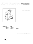
EXTRACTOR
Operation & Maintenance Manual
US & Foreign Patents Pending
The design features herein are protected under the laws of the
United States Patent and Trademark Office
Super Cooling Ducting System
6 Gallon Carpet Extractor
Models
2-100
3-100
2-200
3-200
2-100-H
3-100-H
2-200-H
3-200-H
Always obtain instruction form an authorized dealer. Unauthorized repair will void the warranty
6 GALLON EXTRACTOR MANUAL
1
SAFETY
WARNING: To reduce risk of fire, electrical shock or injury:
•READ ALL INSTRUCTIONS BEFORE USING THIS EXTRACTOR.
•Use only as described in this manual.
•Test all outlets with an outlet tester before plugging machine into any outlet.
•Use only the attachments recommended by the manufacturer.
•Plug cord into the nearest grounded outlet.
•Do not unplug by pulling on the cord, grasp the plug. Do not pull unit by the cord.
•Keep cord away from heated surfaces.
•Never attempt adjustments or repairs while the machine is plugged in.
•Do not use if cord or plug are damaged.
•Do not use outdoors, in standing water, or on wet surfaces.
•Pay close attention when using machine near children.
•Do not pick up flammable or combustible materials, or use machine where they may be present.
•Do not leave machine outdoors, in extreme heat or cold. Harsh weather elements will damage components
and void warranty.
•Lift using only the appropriate handles.
•Always wear the appropriate clothing and safety equipment when operating the machine.
•Keep all body parts, hair and loose clothing away form openings and moving parts
•Use extra care when cleaning stairs. Never move the machine up or down stairs with fluid in the machine.
•Use common sense to protect yourself and others from injury when using the machine.
SET UP AND OPERATION
ELECTRICAL
Plug cord(s) in to 20 AMP grounded wall outlets. 20AMP circuits are normally found in kitchens and bathrooms. Never
remove ground prong from from plug. If a circuit breaker trips during operation, turn machine off, reset the breaker and
move the electrical cord to a different outlet and resume operation.
PUMP SYSTEM
Fill the solution tank and prime the pump (200 psi model only)
-Turn the Auto Prime lever on (Vertical). Auto Prime lever is located on the backside of the machine near the left
power cord.
-Turn on a vacuum motor and cover vacuum inlet for 5-10 seconds.
-Remove hand from inlet and turn the Auto Prime lever off (Horizantal)
-Turn solution pump on and pump should be primed. If pressure does not rise repeat process.
VACUUM SYSTEM
The extractor uses a two vacuum motor system that provides outstanding water lift and air flow. The extractor can be used
with one motor for cleaning delicate fabrics or both motors for carpet cleaning and water extraction.
Automatic Vacuum Shut Off: The float assembly shut off, located in the recovery tank on the vacuum stand pipe, prevents the waste tank from overflowing into the stand pipe and damaging the vacuum motors. The float assembly will cut
off vacuum to the waste tank. When this happens immediately turn off the vacuum motors and empty the waste tank.
The float assembly will also prevent lint and debris from entering the vacuum motors. It is necessary to clean the screen
frequently to maintain maximum vacuum.
It is also necessary to use low foaming chemicals or a defoamer to eliminate foam build up in the recovery tank and damage to the vacuum motors. If moisture does enter the vacuum motors it is necessary to WD-40 the motors. Remove the
float assembly from the stand pipe and turn on both vacuum motors. Spray a five second burst of WD-40 into the stand
pipe and continue to let the vacuum motors run for three minutes.
US & Foreign Patents Pending
The design features herein are protected under the laws of the
United States Patent and Trademark Office
Super Cooling Ducting System
6 GALLON EXTRACTOR MANUAL
2
STORAGE AND FREEZE PROTECTION
You must Winterize your extractor to protect the pump system from freezing. Damage due to freezing is not covered under
the Limited Warranty. Store your extractor in temperatures over 40ºF. If you plan on storing your extractor in freezing conditions you must prime your sniper with antifreeze.
200 and 500 models: Fill the solution tank with 1/2 gallon of 50/50 mix of antifreeze and water and follow the priming
instructions in the set up and operation section of this manual. Vacuum excess mixture out of the solution tank into the
recovery tank and dispose of antifreeze properly.
100 psi models: Fill the solution tank with a 50/50 mix of antifreeze and water and use the wand to spray mixture into a
bucket. Vacuum excess mixture out of the solution tank into the recovery tank and dispose of antifreeze properly.
Be sure to flush out pump and vacuum system thoroughly with fresh water before use.
MAINTENANCE
Regular maintenance is required to keep your extractor in proper working condition.
Thoroughly clean all equipment and accessories after each use.
-Rinse the solution and recovery tanks with clean water.
-Flush the pump system with clean water, including all hoses and wand(s).
-Do not allow water to remain in the tanks after use
Lubricate all quick disconnects with WD-40 or similar lubricant.
200psi Pump Maintenance
-Every week rinse pump out with one gallon of water mixed with 4 ounces of vinegar
-Every 500 hours replace Plunger and Seal kit, and Valve kit.
-Every 1000 hours replace the Cam and Bearing kit.
LIMITED WARRANTY
All equipment is inspected and tested before shipping from the manufacturer. All parts are warranted to be new and free
from defects in workmanship and material to the original retail purchaser as following:
-5 years on plastic body parts
-2 years on electrical and motors
-1 year on pump
This warranty limits manufacturer’s liability for defects in workmanship or materials to replacement of defective parts only.
Manufacturer accepts no liability for incidental or consequential damages arisen from the use of any equipment, defective
or not. This warranty is in lieu of all expressed or implied warranties and is extended only to the original retail purchaser.
Manufacturer sales and service representatives are not authorized to waive or alter the terms of this warranty, or to increase the obligations of the manufacturer under the warranty.
WARRANTY PROCEDURE
It is the responsibility of the distributor to repair the customer’s equipment as soon as possible. If the distributor does
not have the facilities to repair the equipment it may be shipped back to an authorized service center for warranty repair,
freight prepaid.
Procedure:
1. When a repair falls within the warranty time period, the distributor must call for an RMA number.
2. All parts and equipment must be returned with an RMA number for evaluation at customers expense. All claims are
subject to an evaluation to determine if warranty will be approved.
3. When warranty is approved, the distributor’s account will be credited for the parts. If the warranty is denied, the distributor’s account will not be credited for any parts. Customer is responsible for any repair, shipping and handling costs.
US & Foreign Patents Pending
The design features herein are protected under the laws of the
United States Patent and Trademark Office
Super Cooling Ducting System
3
6 GALLON EXTRACTOR MANUAL
TROUBLE SHOOTING GUIDE
System
Vacuum System
Electrical
System
Problem
No Vacuum /
Weak Vacuum
Unit will not turn on
Burning smell
Pump System
Pump is not running
properly
Possible Cause
Remedy
1. Vac tank full
2. Float shut off tank screen dirty
3. Float ball stuck
4. Damaged or loose vac hose
5. Dump valve open
6. Access lid not sealed
7. Vac hose clogged
8. Air intake grid clogged
9. Leak in recovery tank
10. Water coming out of vacuum exhaust
1. Empty tank
2. Clean the screen with water
3. Tap float to unstick and then clean
4. Attach or replace
5. Close valve
6. Replace gasket
7. Clear debris
8. Clean
9. Clean and dry area, patch with silicone
10. Use a low foaming detergent
1. Extension cord not plugged in
2. Switch not in the “ON” position
3. Building circuit overloaded
4. Wiring connections loose
1. Check if machine and cord are plugged in
2. Check switches, replace if necessary
3. Reset circuit
4. Unplug machine and check for loose wires
1. Vacuum motor hung up
2. Pump motor hung up
1. Replace Vacuum motor
2. Replace pump
1. No power to the pump
2. Jets on wand are clogged
3. In-line water filter is clogged
4. Debris in solution tank covering inlet
5. Kinked or loose hose
6. Pump failed
7. Quick disconnects are not
completely locked together
8. Heater is clogged with deposits
1. Check electrical system
2. Clean jet filters
3. Clean in-line filter
4. Clear debris
5. Check and replace hoses if necessary
6. Replace pump
7. Snap quick disconnects together
9. Pump is pulsating
10. Auto Prime valve is open
8. Flush heater with system maintainer or
replace if necessary
9. Check for clogged jets and clean
10. Close valve
3-Stage Motor
10-0810
100psi FloJet Pump
2-Stage Motor
10-0811
100psi Shurflo
Motor Gasket
10-1030 2-Stage
10-1030-S 3-Stage
200psi Pump Tec
10-0812
10-0812-S
10-0869
Cooling Duct-
Shut Off Assem-
300psi Gauge
80-0012
80-0059
T-A001
Dump Valve
10-0805
Female Quick Disconnect
10-0868
Intake/Exhaust
10-0822
Lighted Switch for Heat-
10-0803-H
Hatch Cover
10-0804
Male Quick Discon-
10-0870
Rebuild Kit for 500psi BPR
80-0061
Switch for Vacuum/
10-0803
Hatch Cover Gas-
10-0804-A
1/4” Strainer
10-0845
Model 2-100
1
5
3
2
4
7
6
M1
BLACK
BLUE
RED
YELLOW
Wiring Diagram
M2
WHITE
GREEN
PUMP
110VAC
POWER
SUPPLY
1- Solution Intake
2- Vacuum Hose
3- Vacuum Motor 1
4- Vacuum Motor 2
5- Vacuum Motor Manifold
6- 100psi Solution Pump
7- Motor Cooling Ducting
BLACK / WHITE
BLUE
RED
YELLOW
BLACK
110VAC
POWER
SUPPLY
M1
M2
WHITE
WHITE
Models 3-100
GREEN
110VAC
POWER
SUPPLY
Models 2-100-H 3-100-H
ORANGE
RED
BLACK / WHITE
BLACK
PURPLE
YELLOW
BLUE
M1
M2
WHITE
110VAC
POWER
SUPPLY
HEATER 1
HEATER 2
110VAC
POWER
SUPPLY
BLACK
BLUE
YELLOW
RED
M1
M2
WHITE
GREEN
PUMP
Models 2-200
110VAC
POWER
SUPPLY
BLACK / WHITE
BLUE
RED
YELLOW
BLACK
110VAC
POWER
SUPPLY
M1
M2
WHITE
WHITE
Models 3-200
GREEN
110VAC
POWER
SUPPLY
ORANGE
RED
BLACK / WHITE
BLACK
PURPLE
YELLOW
BLUE
M1
M2
WHITE
110VAC
POWER
SUPPLY
HEATER 1
HEATER 2
Models 2-200-H, 3-200-H
110VAC
POWER
SUPPLY
BLACK / WHITE
BLUE
RED
YELLOW
BLACK
110VAC
POWER
SUPPLY
M1
M2
WHITE
GREEN
WHITE
GREEN
PUMP
Models 2-500, 3-500
110VAC
POWER
SUPPLY
ORANGE
RED
BLUE
M1
M2
110VAC
POWER
SUPPLY
HEATER 1
HEATER 2
Models 2-500-H, 3-500-H
BLACK / WHITE
BLACK
PURPLE
YELLOW