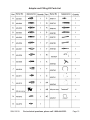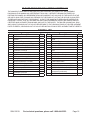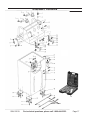
1
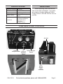
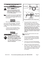
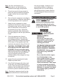
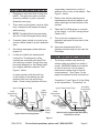
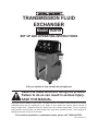
TRANSMISSION FLUID
EXCHANGER
Model 93019
SET UP AND OPERATING INSTRUCTIONS
Visit our website at: http://www.harborfreight.com
Read this material before using this product.
Failure to do so can result in serious injury.
SAVE THIS MANUAL.
Copyright© 2010 by Harbor Freight Tools®. All rights reserved. No portion of this manual or any artwork
contained herein may be reproduced in any shape or form without the express written consent of
Harbor Freight Tools. Diagrams within this manual may not be drawn proportionally. Due to continuing
improvements, actual product may differ slightly from the product described herein. Tools required for
assembly and service may not be included.
For technical questions or replacement parts, please call 1-800-444-3353.
Manual Revised 10f
NOTICE is used to
address practices not
related to personal injury.
SAVE THIS MANUAL
Keep this manual for the safety warnings
and precautions, assembly, operating,
inspection, maintenance and cleaning
procedures. Write the product’s serial number
in the back of the manual near the assembly
diagram (or month and year of purchase if
product has no number). Keep this manual
and the receipt in a safe and dry place for
future reference.
a.
IMPORTANT SAFETY
INFORMATION
Keep the work area clean and well
lighted. Cluttered benches and dark
areas increase the risks of electric
shock, fire, and injury to persons.
b.
Do not operate the tool in explosive
atmospheres, such as in the presence
of flammable liquids, gases, or dust.
The tool is able to create sparks resulting
in the ignition of the dust or fumes.
c.
Keep bystanders, children, and
visitors away while operating the tool.
Distractions are able to result in the loss
of control of the tool.
In this manual, on the labeling, and
all other information provided with
this product:
This is the safety alert
symbol. It is used to alert
you to potential personal
injury hazards. Obey all
safety messages that follow
this symbol to avoid possible
injury or death.
DANGER indicates a
hazardous situation
which, if not avoided, will result
in death or serious injury.
WARNING indicates a
hazardous situation
which, if not avoided, could
result in death or serious injury.
CAUTION, without the
safety alert symbol, is
used to address practices not
related to personal injury.
Work area
Personal safety
a.
Stay alert. Watch what you are
doing and use common sense when
operating the tool. Do not use the
tool while tired or under the influence
of drugs, alcohol, or medication. A
moment of inattention while operating
the tool increases the risk of injury to
persons.
b.
Dress properly. Do not wear loose
clothing or jewelry. Contain long hair.
Keep hair, clothing, and gloves away
from moving parts. Loose clothes,
jewelry, or long hair increases the risk
of injury to persons as a result of being
caught in moving parts.
c.
Do not overreach. Keep proper
footing and balance at all times.
Proper footing and balance enables
CAUTION, used with
the safety alert
symbol, indicates a hazardous
situation which, if not avoided,
could result in minor or moderate
injury.
SKU 93019
For technical questions, please call 1-800-444-3353.
Page 2
better control of the tool in unexpected
situations.
d.
Use safety equipment. A
dust mask, non-skid safety
shoes and a hard hat must be
used for the applicable
conditions. Wear heavy-duty work
gloves during use.
Maintain the tool with care. Keep a
cutting tool sharp and clean. A properly
maintained tool, with sharp cutting edges
reduces the risk of binding and is easier
to control.
f.
Check for misalignment or binding
of moving parts, breakage of parts,
and any other condition that affects
the tool’s operation. If damaged,
have the tool serviced before using.
Many accidents are caused by poorly
maintained tools. There is a risk of
bursting if the tool is damaged.
g.
Use only accessories that are
identified by the manufacturer for
the specific tool model. Use of an
accessory not intended for use with the
specific tool model, increases the risk of
injury to persons.
Always wear eye protection.
Wear ANSI-approved safety
goggles.
e.
f.
e.
Always wear hearing
protection when using the
tool. Prolonged exposure to
high intensity noise is able to
cause hearing loss.
Tool use and care
a.
b.
c.
d.
Do not force the tool. Use the correct
tool for the application. The correct tool
will do the job better and safer at the rate
for which the tool is designed.
Do not use the tool if the switch does
not turn the tool on or off. Any tool that
cannot be controlled with the switch is
dangerous and must be repaired.
Disconnect the tool from the
air source before making any
adjustments, changing accessories,
or storing the tool. Such preventive
safety measures reduce the risk of
starting the tool unintentionally. Turn
off and detach the air supply, safely
discharge any residual air pressure, and
release the throttle and/or turn the switch
to its off position before leaving the work
area.
Store the tool when it is idle out of
reach of children and other untrained
persons. A tool is dangerous in the
hands of untrained users.
SKU 93019
Service
a.
Tool service must be performed only
by qualified repair personnel.
b.
When servicing a tool, use only
identical replacement parts. Use only
authorized parts.
c.
Use only the lubricants supplied
with the tool or specified by the
manufacturer.
Air source
a.
Never connect to an air
source that is capable of
exceeding 90 psi. Over
pressurizing the tool may
cause bursting, abnormal operation,
breakage of the tool or serious injury to
persons. Use only clean, dry, regulated
compressed air at the rated pressure or
within the rated pressure range as
marked on the tool. Always verify prior to
using the tool that the air source has
For technical questions, please call 1-800-444-3353.
Page 3
been adjusted to the rated air pressure
or within the rated air-pressure range.
b.
Never use oxygen, carbon dioxide,
combustible gases or any bottled gas
as an air source for the tool. Such
gases are capable of explosion and
serious injury to persons.
Symbol
WARNING marking concerning Risk of
Explosion.
Specific Safety Instructions
1.
The warnings and precautions discussed
in this manual cannot cover all possible
conditions and situations that may occur.
It must be understood by the operator
that common sense and caution are
factors which cannot be built into this
product, but must be supplied by the
operator.
2.
WARNING: The brass components of
this product contain lead, a chemical
known to the State of California to cause
birth defects (or other reproductive
harm). (California Health & Safety code
§ 25249.5, et seq.)
3.
Only use with accessories rated to
handle the forces exerted by this tool
during operation. Other accessories not
designed for the forces generated may
break and forcefully launch pieces.
4.
Attach all accessories properly to the tool
before connecting the air supply. A loose
accessory may detach or break during
operation.
5.
Wear ANSI-approved splash resistant
safety goggles during use and
maintenance. Always protect your
skin and eyes from contact with oil and
solvents.
6.
Do not smoke near this unit. Keep a
type ABC fire extinguisher nearby in
case of fire.
7.
Use in a well ventilated area.
8.
When leaks are found in the equipment
or hoses, immediately turn the air
pressure off and repair the leaks. Keep
SAVE THESE
INSTRUCTIONS.
SYMBOLS AND SPECIFIC
SAFETY INSTRUCTIONS
Symbol Definitions
Symbol
no
Property or statement
No-load speed
.../min
Revolutions or reciprocation per minute
PSI
Pounds per square inch of pressure
ft-lb
Foot-pounds of torque
BPM
Blows per minute
CFM
Cubic Feet per Minute flow
SCFM
Cubic Feet per Minute flow at standard
conditions
NPT
National pipe thread, tapered
NPS
National pipe thread, straight
WARNING marking concerning Risk of
Eye Injury. Wear ANSI-approved eye
protection.
WARNING marking concerning Risk of
Hearing Loss. Wear hearing protection.
WARNING marking concerning Risk
of Respiratory Injury. Wear NIOSHapproved dust mask/respirator.
Chart continued in next column.
SKU 93019
Property or statement
For technical questions, please call 1-800-444-3353.
Page 4
an empty plastic bucket nearby in case
of leaks.
9.
Immediately clean up any fluid spills or
leaks.
10. Do not exceed the recommended
90 PSI operating air pressure. This
could damage equipment or create a
hazardous situation.
that common sense and caution are
factors which cannot be built into this
product, but must be supplied by the
operator.
SAVE THESE
INSTRUCTIONS.
11. When cleaning, only use cleaning
compounds made for use with
transmissions.
12. Empty all new and used fluid from the
system, disconnect the air supply, and
ensure that the system is not pressurized
before changing the fluid filter or
performing any other maintenance or
repair procedures to the Transmission
Oil Exchanger.
13. Industrial applications must follow OSHA
guidelines.
14. Obey the manual for the air compressor
used to power this tool.
15. Install an in-line shutoff valve to allow
immediate control over the air supply
in an emergency, even if a hose is
ruptured.
16. Maintain labels and nameplates on the
compressor. These carry important
safety information. If unreadable or
missing, contact Harbor Freight Tools for
a replacement.
17. This product is not a toy. Keep it out of
reach of children.
18. Operate unit on level surface only.
19. The warnings, precautions, and
instructions discussed in this instruction
manual cannot cover all possible
conditions and situations that may occur.
It must be understood by the operator
SKU 93019
For technical questions, please call 1-800-444-3353.
Page 5
SPECIFICATIONS
Working Air Pressure
70-90 PSI
Air Inlet
1/4” - 18 NPT
Air Consumption
5.3 CFM @ 90 PSI
Storage Capacity
Accessories
UNPACKING
Two 8-Gallon Storage
Tanks
2 Fluid Collecting Bottles
24 Fitting and Adapters
8 Assorted Hoses
1 Tool Box
1 Spare Oil Filter
When unpacking, make sure that the
item is intact and undamaged. If any parts
are missing or broken, please call Harbor
Freight Tools at 1-800-444-3353 as soon as
possible.
COMPONENTS AND CONTROLS
Used Oil
View Flow
New Oil
View Flow
Oil
Fill
Cap
Air Pressure
Gauge
Pump Pressure Gauge
Air Input
Pressure /
Recycle Control
Used
Oil
Tank
Air
Pressure
Regulator
Control
Filling / Recycle
Control
New Oil
Input Hose
Connector
Pressure
Adapter
Quick
Connector
New
Oil
Tank
Fill
Gauge
Fill
Gauge
SKU 93019
Return
Adapter
Quick
Connector
For technical questions, please call 1-800-444-3353.
Page 6
INITIAL TOOL SET UP/
ASSEMBLY
Coupler
Plug
Exchanger
Read the ENTIRE IMPORTANT
SAFETY INFORMATION
section at the beginning of this
manual including all text under
subheadings therein before set up
or use of this product.
Quick
Coupler
Valve
Quick
Coupler
1.
• This air tool may be shipped with a
protective plug covering the air inlet.
Remove this plug before set up.
Air Supply
TO PREVENT
EXPLOSION:
Use only clean, dry, regulated,
compressed air to power this
tool. Do not use oxygen, carbon
dioxide, combustible gases, or
any other bottled gas as a power
source for this tool.
SKU 93019
Filter
Regulator with
Pressure Gauge
Recommended Air Line Components
Unpacking
Dryer
Air Hose
on Reel
Air
Compressor
Note: For additional information regarding the
parts listed in the following pages, refer
to the Assembly Diagram near the end of
this manual.
When unpacking, make sure that the
item is intact and undamaged. If any parts
are missing or broken, please call Harbor
Freight Tools at 1-800-444-3353 as soon as
possible.
Coupler
Plug
Incorporate a filter, regulator with
pressure gauge, dryer, in-line shutoff
valve, and quick coupler for best service,
as shown in the diagram above. An inline shutoff ball valve is an important
safety device because it controls
the air supply even if the air hose is
ruptured. The shutoff valve should be
a ball valve because it can be closed
quickly.
Note: An oiler system should not be used
with this tool.
2.
Turn the Fluid Exchanger air regulator
counterclockwise to shut off air supply
to pump; refer to Operation section for
description of controls.
3.
Close the in-line shutoff valve between
the compressor and the Fluid Exchanger.
4.
Attach an air hose to the compressor’s
air outlet. Connect the air hose to the air
inlet of the tool. Other components, such
as a coupler plug and quick coupler, will
make operation more efficient, but are
not required.
For technical questions, please call 1-800-444-3353.
Page 7
Note: Air flow, and therefore tool
performance, can be hindered by
undersized air supply components.
5.
The air hose must be long enough to
reach the work area with enough extra
length to allow free movement while
working.
6.
Turn on the air compressor according to
the manufacturer’s directions and allow it
to build up pressure until it cycles off.
7.
Adjust the air compressor’s output
regulator so that the air output is enough
to properly power the tool, but the output
will not exceed the tool’s maximum
air pressure at any time. Adjust the
pressure gradually, while checking the
air output gauge to set the right pressure
range.
8.
If the tool requires more force to
accomplish the task, verify that the
tool receives sufficient, unobstructed
airflow (CFM) and increase the pressure
(PSI) output of the regulator up to the
maximum air pressure rating of this tool.
9.
CAUTION! TO PREVENT TOOL AND
ACCESSORY FAILURE, RESULTING
IN INJURY: Do not exceed the tool’s
maximum air pressure rating (90 PSI).
If the tool still does not have sufficient
force at maximum pressure and
sufficient airflow, then a larger tool may
be required.
10. Inspect the air connections for leaks.
Repair any leaks found.
11. If the Fluid Exchanger will not be used
at this time, turn off and detach the air
supply, safely discharge any residual air
pressure, and turn the switch to its off
position to prevent accidental operation.
Note: Residual air pressure should not be
present after the tool is disconnected
SKU 93019
from the air supply. However, it is a
good safety measure to attempt to
discharge the tool in a safe fashion
after disconnecting to ensure that the
Fluid Exchanger is disconnected and
unpowered
OPERATING INSTRUCTIONS
Read the ENTIRE IMPORTANT
SAFETY INFORMATION
section at the beginning of this
manual including all text under
subheadings therein before set up
or use of this product.
Tool Set Up
TO PREVENT
SERIOUS INJURY
FROM ACCIDENTAL
OPERATION:
Disconnect and remove air
supply before performing any
inspection, maintenance, or
cleaning procedures.
TO PREVENT SERIOUS INJURY:
DO NOT OPERATE WITH ANY
GUARD DISABLED, DAMAGED,
OR REMOVED. Moving guards
must move freely and close
instantly.
Do not start the vehicle engine
in a closed garage or any
other sealed structure. Carbon
monoxide is produced during
operation and is deadly in a
closed environment. Early signs
of carbon monoxide poisoning
resemble the flu, with headaches,
dizziness, or nausea. If you have
any of these signs get fresh air
immediately.
For technical questions, please call 1-800-444-3353.
Page 8
a secondary transmission cooler in
addition to the cooler in the radiator. See
Figure 1, below.
Work Piece and Work Area Set Up
1.
2.
Designate a work area that is clean and
well-lit. The work area must not allow
access by children or pets to prevent
distraction and injury.
There must not be objects, such as utility
lines, nearby that will present a hazard
while working
3.
NOTE: Circulate (bleed) any remaining
test oil in Fluid Exchanger before using.
4.
If needed, place vehicle on a hoist or on
secure vehicle stands in a well ventilated
area.
5.
Set vehicle emergency brake and turn
engine off.
6.
Locate and identify the transmission
cooling line. Transmission cooling
systems are essentially the same from
one vehicle to another, though they may
be routed differently or the fittings might
be in slightly different locations. See
Figure 1, below.
7.
Refer to the vehicle manufacturer’s
maintenance manual and adhere to all
safety warnings and instructions in this
manual.
8.
Place the Fluid Exchanger to one side
of the vehicle. Lock the Locking Swivel
Casters (30).
9.
Turn on the air compressor (not
supplied) and place its hose next to the
Exchanger.
10. Have new transmission fluid or
cleaning solvent ready for use near the
Exchanger.
Making Vehicle Service Connections
1.
In some systems, both lines will run
to the bottom of the radiator, as with
radiators that have top and bottom
tanks. Some cooling systems will have
Connection 1 (see Figure 2) is the fitting
at the transmission. Connection 2 is
Upper Transmission Fitting
Upper Transmission Fitting
Upper
Radiator
Fitting
Lower
Transmission
Fitting
Lower
Transmission
Fitting
Secondary
Transmission
Cooler
Cooling
Lines
Cooling
Lines
Typical Vehicle Cooling System
The fittings required vary based on
vehicle make and often from model to
model. WARNING! Make sure vehicle
is shut off and cool. Do not open a
transmission system that is hot and
under pressure. See Figure 2 (next
page) for standard hookup connections.
Lower
Radiator
Fitting
Vehicle Cooling System With Secondary
Transmission Cooler
Figure 1
SKU 93019
For technical questions, please call 1-800-444-3353.
Page 9
Connection 1:
Transmission Fitting
Connection 2:
Upper/Lower
Radiator
Fitting
Upper Transmission
Fitting
Upper
Radiator
Fitting
Cooling
Lines
Lower Transmission
Fitting
Connection 3:
Upper/Lower Cooling Line
Lower Radiator
Fitting
Hookup Top Radiator Line
Typical Cooling Connection Locations
Figure 2
the fitting at the radiator. Connection 3
shows a spot (typical to foreign vehicles)
where a rubber hose changes to a steel
tubing line.
8.
Radiator
Please note: There must be a
removable hose clamp at this location in
order to make a connection. Only a few
vehicles will be serviced at this location.
2.
For the connection steps, we will use
a guide for a 1992 Chevrolet 4-Door
Blazer, as shown in Figure 2, above.
3.
First, verify the transmission fluid level is
normal before you begin.
4.
Look for the easiest spot to break into
the transmission system (any existing
connection along the entire system can
be used, as shown in Figure 2, above.)
5.
If available, use a transmission cooling
line wrench (such as an open end
wrench, flare nut wrench, or adjustable
wrench) to remove the transmission
cooling line from the radiator.
6.
7.
Examine the vehicle fittings and compare
them to the one shown on the Fitting
Chart on page 16 of this manual.
Connect required fitting into radiator and
then connect required female fitting onto
the vehicle transmission cooling line.
SKU 93019
The red delivery line is attached to the
fitting just installed on the radiator. See
Figure 3, below.
Fitting
Red Line
Figure 3
9.
NOTE: The connections only need
to be snug fit. Torquing down hard
is not required, they should be tight
enough to keep the connections from
leaking. If they begin to leak, see the
Troubleshooting section on page 14.
10. Connect the black return hose to the
fitting just installed on the transmission
cooling line. This is the same line that
was removed from the radiator (as
mentioned in Step 5). See Figure 4.
Cooling
Line
Return Hose
Fitting
Figure 4
For technical questions, please call 1-800-444-3353.
Page 10
11. Make certain the hose clamp is tightened
on the inside of the hose clamp flare on
each fitting. This will keep the hose form
coming off.
12. WARNING! Do not overtighten the
adapter hose clamps. Doing so will
damage the hose ends over a period of
time. Clamp the hoses down with a snug
fit only. See Troubleshooting section if
there are still leaks.
13. Connect red (pressure) and black
(return) lines to corresponding quick
couplers on the Fluid Exchanger. See
Figure 5. You are not required to
account for fluid flow when making
connection. The Exchanger will sense
the vehicle’s fluid direction and send
used fluid from vehicle so that it flows
into the used oil tank and send new
oil from new oil tank and to vehicle’s
transmission. Once red and black
service hoses have been connected, the
system should look as shown in Fig. 5.
Filling Cleaning Fluids
1.
Make Service Connections as previously
described.
2.
Using one of the Adapter Kit clear hoses
or the second Red Hose, connect it to
the New Oil Input Hose Connector. Insert
the other end into the solvent container
(to the bottom). Refer to the vehicle
manufacturer’s maintenance manual for
approved cleaning solvents.
3.
Turn the Pressure Recycle Control knob
to the Pressure position.
4.
Turn the Recycle-Filling Control knob to
the Filling position.
5.
Connect the air compressor line hose
to the Air Input Quick Connector on the
Fluid Exchanger.
6.
While viewing the Air Pressure Gauge,
pull up on the Air Pressure Regulator
Control knob and adjust the air pressure
to between 40 and 90 PSI. (Check
the required pressure in the vehicle
manufacturer’s maintenance manual.)
The cleaning solvent in now injected into
the transmission.
NOTE: With some make and models of
the vehicle being serviced, the use of
other included fittings and/or hoses may
be needed to make service connections.
Transfer Hoses
Figure 5
SKU 93019
For technical questions, please call 1-800-444-3353.
Page 11
7.
Turn the (left) Pressure Recycle Control
knob to the Recycle position.
8.
Turn the (right) Filling-Recycle Control
knob to the Recycle position.
9.
Start the engine to begin the cleaning
process. This should take five minutes.
During this process, view the fluid flow
through the View Flow tubes.
10. Turn the engine off after five minutes.
Control knob and adjust the air pressure
to between 40 and 90 PSI. The air
pressure will force the new oil into the
transmission, and the old oil will be
forced into the Used Oil Tank. (During
this process, view the new and used oil
flow. They should flow in and out at
equal rates. Adjust the air pressure, if
necessary, to accommodate this.)
9.
11. Remove the air compressor line and
remove hose from the side “Filling”
coupler.
12. Begin steps for the Oil Exchange Cycle.
During the oil transfer process, with your
foot securely holding down the brake,
switch gears in sequential order, starting
with first gear. Keep in each gear for 10
seconds.
Oil Exchange Cycle
1.
Leave the Black Hose (return) and the
Red Hose (pressure) connected as
described in the previous steps, but
disconnect the hose to the New Oil Input
Hose Connector. See Figure 3, below.
2.
Review the vehicle manufacturer’s
maintenance manual for the correct type
and amount of transmission fluid oil.
3.
NOTE: Verify Fluid Exchanger system
has been purged.
4.
Remove the Oil Fill Cap on the top of the
Fluid Exchanger and pour in the correct
amount of new transmission fluid oil.
View the amount of fluid filling the New
Oil Tank Gauge.
5.
Turn the Pressure Recycle Control knob
to the Pressure position.
6.
Turn the Recycle-Filling Control knob to
the Recycle position.
7.
Connect the air compressor line hose to
the Air Input Quick Connector.
8.
While viewing the Air Pressure Gauge,
pull up on the Air Pressure Regulator
SKU 93019
Start the engine and view the oil flow
through the New and Used Oil View Flow
tubes. When the color of the oil is has
shifted from light brown (old oil) to red
(newer oil) in both tubes, the process is
complete.
10. Turn the engine off and remove air line.
11. Reconnect the vehicle oil output (return)
line from the transmission to the input
of the automatic transmission cooler.
Securely tighten clamps. Make certain
that the transmission is properly filled
and not overfilled before using the
vehicle.
Emptying Old Oil
1.
Using an Adapter Hose from the kit,
connect one end to the New Oil Input
Hose Quick Connector, and the other
end to the Return Adapter Quick
Connector.
2.
Connect a Black Hose to Pressure
Adapter Quick Connector. Place other
end of the Black Hose in an appropriate
disposal tank of adequate size.
3.
Turn the Pressure-Recycle Control knob
to the Pressure position.
For technical questions, please call 1-800-444-3353.
Page 12
4.
Turn the Recycle-Filling Control knob to
the Filling position.
5.
Connect the air compressor line hose to
the Air Input Quick Connector.
6.
While viewing the Air Pressure Gauge,
pull up on the Air Pressure Regulator
Control knob and adjust the air pressure
to between 40 and 90 PSI. View the
used oil movement from the Used Oil
View Flow tube.
7.
When all used oil is removed from the
Used Oil Tank, remove the air line from
the. Remove the other hoses as well.
8.
Dispose of used oil and solvents in
a proper manner as dictated by local
environmental codes.
USER-MAINTENANCE
INSTRUCTIONS
Cleaning, Maintenance, and
Lubrication
Note: These procedures are in addition to
the regular checks and maintenance
explained as part of the regular operation
of the air-operated tool.
1.
Daily - Air Supply Maintenance:
Every day, perform maintenance on the
air supply according to the component
manufacturers’ instructions. If needed,
the lubricator’s oil level needs to be
maintained. And the moisture filter must
be regularly drained. Performing routine
maintenance on the air supply will allow
the tool to operate more safely and will
also reduce wear on the tool.
2.
Drain all hoses that were used in an
appropriate oil disposal tank.
3.
When finished using the Fluid
Exchanger, coil the Red and Black
Hoses and place in the side holder.
Place the Adapter Fittings and Hoses
back in their case. Store the case in the
top-back of the Fluid Exchanger.
4.
Before each use, discharge any water
accumulation from the air compressor
tank. A water filter on the air compressor
is recommended.
5.
When oil flow through the Fluid
Exchanger very slowly, even with
higher air pressure, replace the Fluid
Exchanger’s oil filter
6.
Quarterly (every 3 months):
Have the pump cleaned and inspected,
by a qualified technician.
Procedures not specifically
explained in this manual must
be performed only by a qualified
technician.
TO PREVENT
SERIOUS INJURY
FROM ACCIDENTAL
OPERATION: Turn off the tool,
detach the air supply, safely
discharge any residual air
pressure in the tool, and turn the
switch to its off position before
performing any inspection,
maintenance, or cleaning
procedures.
TO PREVENT SERIOUS INJURY
FROM TOOL FAILURE: Do not
use damaged equipment. If
abnormal noise, vibration, or
leaking air occurs, have problem
corrected before further use.
SKU 93019
For technical questions, please call 1-800-444-3353.
Page 13
Troubleshooting
Problem
Possible Causes
Decreased output. 1. Not enough air pressure and/
or air flow.
Likely Solutions
1. Check for loose connections and make sure that air
supply is providing enough air flow (CFM) at required
pressure (PSI) to the tool’s air inlet. Do not exceed
maximum air pressure of 90 PSI.
2. Clean air inlet screen of buildup.
2. Blocked air inlet screen (if
equipped).
3. Air leaking from pump housing 3. Make sure the pump is properly assembled and tight.
or fittings.
4. Pump contaminated.
4. Inspect and clean pump. Install in-line filter in air
supply as stated in Initial Set Up: Air Supply.
5. Fluid lines kinked or bent.
5. Straighten fluid lines.
1. Incorrect settings of control
1. Adjust control knobs to correct settings.
knobs.
2. Incorrect (reversed) hose
2. Verify direction of oil inlet and oil return hoses correct;
installation.
adjust if necessary.
1. Incorrect components and/or
1. Verify correct fittings are being sued with correct
fittings installed.
vehicle transmission system.
Hoses are
connected, but oil
flow is not seen
from view tubes.
Severe air
leakage.
(Slight air leakage
is normal,
2. Damaged hoses and/or
2. Replace damaged hoses and/or fittings.
especially on older
fittings.
tools.)
3. Air leaking from pump housing. 3. Make sure the pump is properly assembled and tight
Follow all safety precautions whenever diagnosing or servicing the tool.
Disconnect air supply before service.
Record Product’s Serial Number Here:
Note: If product has no serial number, record month and year of purchase instead.
Note: Some parts are listed and shown for illustration purposes only, and are not available
individually as replacement parts.
SKU 93019
For technical questions, please call 1-800-444-3353.
Page 14
Adapter and Fitting Kit Parts List
SKU 93019
For technical questions, please call 1-800-444-3353.
Page 15
PLEASE READ THE FOLLOWING CAREFULLY
THE MANUFACTURER AND/OR DISTRIBUTOR HAS PROVIDED THE PARTS LIST AND ASSEMBLY
DIAGRAM IN THIS MANUAL AS A REFERENCE TOOL ONLY. NEITHER THE MANUFACTURER OR
DISTRIBUTOR MAKES ANY REPRESENTATION OR WARRANTY OF ANY KIND TO THE BUYER THAT HE
OR SHE IS QUALIFIED TO MAKE ANY REPAIRS TO THE PRODUCT, OR THAT HE OR SHE IS QUALIFIED
TO REPLACE ANY PARTS OF THE PRODUCT. IN FACT, THE MANUFACTURER AND/OR DISTRIBUTOR
EXPRESSLY STATES THAT ALL REPAIRS AND PARTS REPLACEMENTS SHOULD BE UNDERTAKEN BY
CERTIFIED AND LICENSED TECHNICIANS, AND NOT BY THE BUYER. THE BUYER ASSUMES ALL RISK
AND LIABILITY ARISING OUT OF HIS OR HER REPAIRS TO THE ORIGINAL PRODUCT OR REPLACEMENT
PARTS THERETO, OR ARISING OUT OF HIS OR HER INSTALLATION OF REPLACEMENT PARTS THERETO.
PARTS LIST
Part
1
2
3
4
5
6
7
8
9
10
11
12
13
14
15
16
17A
18A
Description
Oil Fill Cap
O-Seal
Gauge, Oil Pressure, 16 kgs
Gauge, Pump Pressure, 16 kgs
Gauge Stand
Quick Connector, PCF10-02
Connector, PCF8-02
Elbow Connector, PL12-02
1/4” Elbow Connector (Cu)
PU Hose, Ø12
3-Way Connector, PD10-02
Air Inlet Connector, 1/4” Male
1/4” Mail Quick Couplet, SM20
1/4” Connector, PC8-02
1/4” Connector, PC10-02
Connector, PL8-02
Connector, PL10-04
Three-Way Ball Valve (Cu)
SKU 93019
Qty.
1
1
1
1
2
3
1
4
2
2
4
1
3
1
5
2
6
2
Part
19A
20A
21
22
23
24
25
26
27
28
29
30
31
32
33
34
35
Description
Knob Connector
Knob
Pressure Regulator
Three-Way Connector, PD8-02
Connector, PL10-02
Filter Cover
Filter
Silencer
Complete Set of Pump
Main Body
Wheels
Casters With Brake
Screws (M8)
1/4” Female Quick Couple, SF20
1/4” Male Quick Connector, PM20
Oil delivery hose with 2 red, 1 black
connectors (not shown)
Tool Box
For technical questions, please call 1-800-444-3353.
Qty.
2
2
1
1
2
1
2
1
1
1
2
2
16
3
3
3
1
Page 16
ASSEMBLY DIAGRAM
35
34
SKU 93019
For technical questions, please call 1-800-444-3353.
Page 17
Hose Connection Diagram
SKU 93019
For technical questions, please call 1-800-444-3353.
Page 18
90 Day Warranty
Harbor Freight Tools Co. makes every effort to assure that its products meet high quality
and durability standards, and warrants to the original purchaser that this product is free from
defects in materials and workmanship for the period of 90 days from the date of purchase. This
warranty does not apply to damage due directly or indirectly, to misuse, abuse, negligence or
accidents, repairs or alterations outside our facilities, criminal activity, improper installation,
normal wear and tear, or to lack of maintenance. We shall in no event be liable for death,
injuries to persons or property, or for incidental, contingent, special or consequential damages
arising from the use of our product. Some states do not allow the exclusion or limitation of
incidental or consequential damages, so the above limitation of exclusion may not apply to
you. THIS WARRANTY IS EXPRESSLY IN LIEU OF ALL OTHER WARRANTIES, EXPRESS
OR IMPLIED, INCLUDING THE WARRANTIES OF MERCHANTABILITY AND FITNESS.
To take advantage of this warranty, the product or part must be returned to us with
transportation charges prepaid. Proof of purchase date and an explanation of the complaint
must accompany the merchandise. If our inspection verifies the defect, we will either repair or
replace the product at our election or we may elect to refund the purchase price if we cannot
readily and quickly provide you with a replacement. We will return repaired products at our
expense, but if we determine there is no defect, or that the defect resulted from causes not
within the scope of our warranty, then you must bear the cost of returning the product.
This warranty gives you specific legal rights and you may also have other rights which vary
from state to state.
3491 Mission Oaks Blvd. • PO Box 6009 • Camarillo, CA 93011 • (800) 444-3353
SKU 93019
For technical questions, please call 1-800-444-3353.
Page 19