1
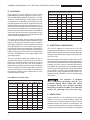
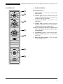
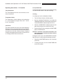
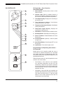
Installation and Operation Manual 613 & E SERIES GAS-FIRED CONVECTION OVEN POWER OVEN OFF COOL DOWN COOK LIGHT OFF OVEN READY TEMPERATURE TIME GAS SHUTOFF ON OFF Qualified Energy Star Models: 613-G1V 613-G2V 613-G1XX 613-G2XX 613Q-G1V 613Q-G2V 613Q-G1XX 613Q-G2XX E101-G E102-G Please read this manual completely before attempting to install, operate or service this equipment This manual is Copyright © 2011 Duke Manufacturing Co. All rights reserved. Reproduction without written permission is prohibited. Duke is a registered trademark of the Duke Manufacturing Co. Duke Manufacturing Co. 2305 N. Broadway St. Louis, MO 63102 Phone: 314-231-1130 Toll Free: 1-800-735-3853 Fax: 314-231-5074 www.dukemfg.com P/N: 153810X Installation and Operation of 613 & E Series Gas Fired Convection Oven TABLE OF CONTENTS IMPORTANT WARNING AND SAFETY INFORMATION...................................................3 SPECIFICATIONS..............................................................................................................4 OVEN INPUT – STANDARD DEPTH..........................................................................4 OVEN INPUT – DEEP DEPTH....................................................................................4 BURNER ORIFICE SIZE.............................................................................................4 INSTALLATION INSTRUCTIONS......................................................................................5 A. Qualified Personnel................................................................................................5 B. Delivery and Inspection..........................................................................................5 C. Location of the Oven..............................................................................................5 D. Gas Piping.............................................................................................................6 E. Electrical Connections...........................................................................................6 F. Ventilation...............................................................................................................6 Venting to a Canopy Exhaust Hood.....................................................................7 Direct Flue Venting...............................................................................................7 Lighting Instructions.............................................................................................7 Shut Down Instructions........................................................................................7 G. Oven Assembly......................................................................................................7 Leg Attachment....................................................................................................7 Caster Installation.................................................................................................7 Installation of the Vent..........................................................................................8 H. Adjustments Associated with Installation...............................................................8 I. Double Sections......................................................................................................8 Mounting Flue Extension to Top Oven.................................................................9 Securing Double-Stacked Ovens.........................................................................9 OPERATING INSTRUCTIONS.........................................................................................10 The “E” and 6/13 Series of Convection Ovens..........................................10 V-Controller...................................................................................................... 11 A. Oven Controls.............................................................................................. 11 Electro-Mechanical............................................................................................. 11 Operating Instructions - “V” Controller................................................12 Timer Resolution................................................................................................12 Temperature Scale.............................................................................................12 Cool Down..........................................................................................................12 Fan Speed Switch..............................................................................................12 Cooking..............................................................................................................12 XX CONTROLLER....................................................................................................13 XX Controller – Oven Controls – Solid State Digital...........................................13 Programming and Operating Instructions – XX Controller.................................13 B. General Guidelines for Operation.........................................................................14 C. Suggested Cook Times & Temperatures.............................................................16 D. Cleaning of the Ovens..........................................................................................17 2 Installation and Operation of 613 & E Series Gas Fired Convection Oven MAINTENANCE INSTRUCTIONS...................................................................................18 A. Adjustments.........................................................................................................18 B. Door Adjustment..................................................................................................18 C. Door Switch Adjustment.......................................................................................18 D. Thermostat Calibration........................................................................................19 To Check Calibration................................................................................................... 19 To Calibrate the Ovens.......................................................................................19 E. Gas Pressure Regulation and Adjustment...........................................................19 F. Ventilation System................................................................................................20 Repair Parts List................................................................................................21 613 Door Assembly (Typical)..........................................................................22 E Series & 613 “V” Controller Assembly....................................................23 XX Gas Control Assembly...............................................................................24 ELECTRICAL SCHEMATIC......................................................................................25 Customer Assistance..............................................................................................26 IMPORTANT WARNING AND SAFETY INFORMATION POST IN A PROMINENT LOCATION instructions to be followed in the event the user smells gas. This information shall be obtained by consulting the local gas supplier. FOR YOUR SAFETY: Do not store or use gasoline or other flammable vapors or liquids in the vicinity of this or any other appliance. : Improper installation, adjustment, alteration, service or maintenance can cause property damage, injury or death. Read the installation, operating and maintenance instructions thoroughly before installing or servicing this equipment. THIS MANUAL MUST BE RETAINED FOR FUTURE REFERENCE. 3 Installation and Operation of 613 & E Series Gas Fired Convection Oven SPECIFICATIONS NATURAL GAS PROPANE GAS HEATING VALUE SPECIFIC GRAVITY GAS PRESSURE AT MANIFOLD 1000 BTU 0.63 3.5" W.C. 37.3 MJ/m3 0.63 0.87 kPa 2550 BTU 1.53 10" W.C. 90.0 MJ/m3 1.53 2.49 kPa OVEN INPUT – STANDARD DEPTH PER BURNER 20,000 BTU/HR 5.9 kW 20.000 BTU/HR 5.9 kW PER OVEN 40,000 BTU/HR 11.8 kW 40,000 BTU/HR 11.8 kW PER BURNER 23,000 BTU/HR 6.8 kW 23.000 BTU/HR 6.8 kW PER OVEN 46,000 BTU/HR 13.5 kW 46,000 BTU/HR 13.5 kW STANDARD DEPTH #44 2.18mm #55 1.32mm DEEP DEPTH #43 2.26mm #54 1.40mm OVEN INPUT – DEEP DEPTH BURNER ORIFICE SIZE 4 Installation and Operation of 613 & E Series Gas Fired Convection Oven INSTALLATION INSTRUCTIONS A. Qualified Personnel B. Delivery and Inspection These installation instructions are for the use of qualified installation and service personnel only. Installation or service by other than qualified personnel may result in damage to the oven and/or injury to the operator. Duke Manufacturing Co. does everything within its power to insure you received your oven in good condition. They are strapped down on heavy wooden skids and surrounded by heavy “tri-wall” cartons to prevent shipping damage. They have all been carefully inspected before they were packaged and consigned to the carrier. Qualified installation personnel are those individuals, firms, companies or corporations which either in person or through an agent is engaged in and responsible for: • • The installation or replacement of gas piping or the connection, installation, repair or servicing of equipment, who are experienced in such work, familiar with all precautions required, and have complied with all requirements of state and local authorities having jurisdiction. See: National Fuel Gas Code NFPA 54 (ANSI Z223.1). The installation of electrical wiring from the electric meter, main control box or service outlet to the electrical appliance. Qualified installation personnel must be familiar with all precautions required and have complied with all requirements of state and local authorities having jurisdiction. See: National Electrical Code, ANSI/NFPA70. The installation must conform with local codes, or in the absence of local codes, with the National Fuel Gas Code, ANSI Z223.1/NFPA 54, or the Natural Gas and Propane Installation Code, CSA B149.1 as applicable, including: • • The appliance and its individual shutoff valve must be disconnected from the gas supply piping system during any pressure testing of that system at test pressures in excess of 1/2 psi (3.5 kPa). The appliance must be isolated from the gas supply piping system by closing its individual manual shutoff valve during any pressure testing of the gas supply piping system at test pressures equal to or less than 1/2 psi (3.5 kPa). For an oven equipped with casters, the installation shall be made with a connector that complies with the Standard for Connectors for Movable Gas Appliances, ANSI Z21.69/CSA 6.16 and a quick-disconnect device that complies with the Standard for Quick-Disconnect Devices for Use with Gas Fuel, ANSI Z21.4/CSA 6.9. When installing the oven with casters and quickdisconnect hose, adequate means must be provided to limit the movement of the oven without depending on the connector and the quick disconnect device or its associated piping to limit the oven movement. Restraining means may be attached to the vertical portion of the base frame in the rear of the oven. Upon delivery of your Duke oven: • Look over the shipping container, carefully noting any exterior damage on the delivery receipt, which must also be signed by the driver/ delivery person. • Uncrate and check for any damage, which was not evident on the outside of the shipping container. This is called concealed damage. The carrier must be notified within fifteen (15) days of the delivery of the oven and the carton, skid and all packaging materials must be retained for inspection. Duke Manufacturing Co. cannot assume liability for loss or damage suffered in transit. The carrier assumes full responsibility for delivery in good order when the shipment was accepted. However, we are prepared to assist you in filing your claim. C. Location of the Oven Proper planning and placement of the oven will give you the best results in terms of long-term user convenience and satisfactory performance. We urge you to give adequate thought in the placement of your oven prior to its arrival. • The oven should be placed in an area that is free from drafts and accessible for proper operation and servicing. • The area around the oven must be kept clear of combustible materials. A minimum clearance must be maintained between the oven and any combustible or non-combustible surface. MINIMUM CLEARANCES Combustible Non-Combustible RIGHT SIDE 1" 0" LEFT SIDE 1" 0" REAR 3" 3" FLOOR 8" 8" 5 Installation and Operation of 613 & E Series Gas Fired Convection Oven D. Gas Piping Each section of the “E” Series or 6/13-G Ovens (standard depth) is rated at 40,000 BTU’s per hour (11.7 kW) or (deep depth) 46,000 BTU’s per hour (13.5 kW). Therefore, 38-40 (standard), 44-46 (deep) cubic feet of natural gas or 16 (standard), 18.4 (deep) cubic feet of propane gas per hour must be supplied to each unit (stacked units count as two) when the oven is full on. In order to achieve the degree of performance for which the unit has been designed, the overall piping plan of the kitchen, properly sized, is essential. The installation of this oven must conform with all local codes, or in the absence of any local codes, to the National Fuel Gas Code, NFPA 54 and ANSI Z 223.1. Your local gas supplier should consult the National Fuel Gas Code for proper sizing and installation of gas piping. Generally, piping should be sized to provide a gas supply sufficient to meet the maximum demand of all gas appliances on a line without undue loss of pressure at the outlet to the equipment. The total BTU requirements of the equipment being served and the length of the piping from the meter to the appliances are major considerations in the proper design of the gas supply system. This oven has been tested and certified for use on gas systems that do not exceed 1/2 psi (3.45 kPa) of pressure. If the piping system is tested at a pressure higher than 1/2 psi (3.45 kPa), this oven should be isolated from the supply by disconnecting it. If the piping system is tested at a pressure lower than or equal to 1/2 psi (3.45 kPa), this oven should be isolated from the supply by shutting off the manual shut off valve located on the front panel. From National Fuel Gas Code: MAXIMUM CAPACITY OF IRON PIPE IN CUBIC FEET PER HOUR (PRESSURE DROP OF 0.5” W.C.) NATURAL GAS 6 Length in Feet 1/2" 3/4" 1" 1-1/2" 2" 10 175 360 680 2100 3950 20 120 250 465 1460 2750 30 97 200 375 1180 2200 40 82 170 320 990 900 50 73 151 285 900 1680 60 66 138 260 810 1520 70 61 125 240 750 1400 80 57 118 220 690 1300 90 53 110 205 650 1220 100 50 103 195 620 1150 MAXIMUM CAPACITY OF PIPE IN THOUSANDS OF BTU’S PER HOUR OF UNDILUTED PROPANE GAS AT 11” W.C. Length in Feet 1/2" 3/4" 1" 10 275 567 1071 20 189 393 732 30 152 315 590 40 129 267 504 50 114 237 448 60 103 217 409 70 96 196 378 80 86 185 346 90 83 173 322 100 78 162 307 E. Electrical Connections Your oven is supplied for connection to a 115 volt, single phase grounded circuit. The electric motor, oven lights, indicator lights and control circuits are connected through a seven-foot electric supply cord found at the rear of the oven. Before making any connections to these units, check the rating plate to assure that the voltage and phase of the oven is compatible with the electrical supply. When installing, all ovens must be electrically grounded in accordance with local codes, or in the absence of local codes, with the National Electrical Code, ANSI/NFPA 70 (in Canada - CSA Std. C22.2). Wiring diagrams are located in the control compartment area of the oven. Standard wiring schematics are also provided with this manual. : This appliance is equipped with a three-prong (grounding) plug for your protection against shock hazard and should be plugged directly into a properly grounded three-prong receptacle. DO NOT cut or otherwise remove the grounding prong from this plug. F. Ventilation Proper ventilation is very important for the proper function of your oven. A good ventilation system will allow the oven to function properly as well as remove unwanted vapors and products of combustion. Not venting the ovens properly can result in unsatisfactory baking results as well as the possibility of damaging Installation and Operation of 613 & E Series Gas Fired Convection Oven your oven. To keep your warranty in force, a proper ventilation system must be employed, either direct vented or under a canopy. Shut Down Instructions: • Turn Power Switch to OFF Position • Wait 5 Minutes Before Relighting Oven Venting to a Canopy Exhaust Hood The best way to vent your oven is by placing it under a properly designed mechanically driven exhaust hood. The hood should be sized so the equipment that it is designed to ventilate fits underneath with a minimum six (6) inch (152 mm) overhang on all sides not adjacent to a wall. The distance from the floor to the lower edge of the canopy should not exceed seven (7) feet (2.2 m). The hood should have adequate capacity and provide a sufficient supply of make- up air. Ventilation hoods come in many sizes and capacities. Hood capacity is expressed in cubic feet per minute (CFM). The total make-up and exhaust air required for the canopy hood should be about 22 CFM per oven section. Information for the proper construction and installation of ventilating hoods may be obtained from the “Standard for the Installation of Equipment for the Removal of Smoke and Grease-Laden Vapors from Commercial Cooking Equipment, NFPA-96”. Direct Flue Venting Occasionally it is not possible or practical to install a powered canopy hood. In those cases the oven can be vented directly by means of a direct flue method. Correctly venting your oven is very important to insure proper cooking results and preclude any premature failures in the burner or burner compartment. The direct flue method incorporates a drafthood that is mounted to the top of the oven (or the upper oven section in a stacked unit). The flue then rises from the drafthood vertically to a point 6-8 feet above the roof or any close structure. The flue is then capped with an approved vent cap to isolate the flue from the external environmental conditions. The direct flue method does not incorporate the ability to replace air consumed by and vented from the oven. An adequate supply of room make-up air must be provided if your oven is to be vented by this method. The total makeup air requirement for one oven section is approximately 30 CFM. Lighting Instructions: • Turn Gas Shut Off to ON Position • Turn Power Switch to COOK Position • Set Thermostat to Desired Temperature : Keep the oven area free and clear from combustibles. Note: This manual must be retained for future reference. G. Oven Assembly Before assembling and installing the oven, please check to make sure that all necessary parts are present. In addition to the oven itself, there will also be legs, feet or casters, the flue/vent guard or drafthood and drafthood collar assembly, (for double sections, retaining clips, flue riser and/or common manifold) and miscellaneous hardware. Please check the interior of all oven sections for the parts needed to assemble and install your oven(s). Leg Attachment • Once the oven has been removed from the carton, lay it on its left side (the side without the controls), hold the leg and align with the threaded holes in the front comer of the bottom of the oven. Carefully start the threads of the comer leg bolt (5/16"-18 X 1/2"), avoid cross threading. • Align the leg plate holes in each leg with those in the corners of the oven bottom and secure using two 5/ 16"-18 x 1/2" bolts. Tighten all bolts firmly. Repeat this procedure for all legs. • Raise the oven up on its legs. Level the oven by turning the adjustable feet in or out as needed. Caster Installation • Casters are available as an option for both the single and double oven sections. • The installation of casters requires the removal of the adjustable feet from the legs. This is done by placing the bit of a large screwdriver against the lip of the foot and rapping the screwdriver to drive the foot out of the leg. The caster is then inserted fully into the opening where the foot came out and the locking nut tightened to expand the compression sleeve of the caster. 7 Installation and Operation of 613 & E Series Gas Fired Convection Oven NOTE: The casters with locking brakes are best mounted on the front side of the oven for easier access. No installation should be considered complete without proper inspection and, if necessary, any adjustments by qualified service or installation personnel. NOTE: If you plan to use casters and flexible fuel gas connectors, a fixed restraint of the proper length must be incorporated to secure the oven to a non-movable surface to eliminate strain on the connector. If the oven is removed from its normal position, the restraint must then be reattached when returned. It is also important not to obstruct the natural flow of combustion and ventilation air if the oven is to operate properly. This oven should not be installed on a curb base or sealed to the wall. Either condition can restrict the flow of air to the combustion compartment or prevent proper ventilation of the blower motor. The blower motor has a thermal protection device that will trip because of excessive ambient temperature at the back of the oven. This condition should be corrected immediately to avoid damaging the oven permanently. Installation of the Vent • • Ovens ordered for installation under a powered canopy exhaust hood should have the flue guard in place. This item can be installed by placing it over the flue opening, making sure that it does not obstruct the flue, and attaching it with the screws provided. Ovens ordered for installation in a location other than under a powered canopy exhaust hood are supplied with a drafthood & drafthood collar. This device mounts to the top of the upper oven section by attaching the drafthood adapter to the flue opening with the screws provided, the drafthood is then mounted on top of the adapter. The flue pipe is attached vertically to the drafthood. H. Adjustments Associated with Installation Each oven section and all its component parts have been tested thoroughly and inspected before your oven was shipped from the factory. However, it is sometimes necessary to further test or adjust the oven once it has been installed. Such adjustments are the responsibility of the Dealer or Installer. These types of adjustments are not considered defects, rather a normal and routine part of the proper installation of the equipment. These adjustments include but are not limited to: • Adjustments and recalibration of the thermostat • Adjustment to the doors • Burner or pilot adjustment. • Adjustments to the gas pressure regulator. • Leveling, and tightening of fasteners. 8 Before making any connections to the oven, check the ratings plate to be sure the oven specifications concur with the type of gas and voltage to be supplied to the oven. The rating plate is located behind the lowered lower front panel. To access, loosen the four screws below the doors, and pull panel outward. The plate bearing the oven's serial number is attached to the underside of the upper ledge above the control panel. I. Double Sections • Secure the short legs to the bottom of the lower section as described in previous section. • Casters are installed by the method described for single section ovens. Previous section. • Place upper section on top of lower section and align all edges of the ovens. • Locate securing clips and align with holes on rear frames of oven section, install three screws each as provided and tighten. • At the rear of the oven, install the flue connector by sliding it up through the flue vent opening in the top of the oven and over the upper flue vent. Push it flush with the back of the oven then slide it down over the lower flue vent. Attach with screws provided. • Install flue guard or drafthood adapter, drafthood and drafthood collar to upper section. Installation and Operation of 613 & E Series Gas Fired Convection Oven Mounting Flue Extension to Top Oven 1. Remove existing flue trim from the top of oven. 2. Insert flue extension thru top opening first and then align holes on flue extension with holes on rear panel of oven. Screws (4) Flue Trim 3. Use 6 of the 8 screws (10-24x1/2") hex washer head that are provided to attach the flue extension to the rear panel of the oven as shown in figure. The other 2 screws are extras and are not used. 4. Re-install the existing flue trim. Flue Extension (153074) 10Ð24 X 1/2" Hex Washer Head Screws (6) Screws (3) Stacking Bracket (153233) Securing Double-Stacked Ovens 1. On rear of top oven remove two existing screws that attach the side panel to the base. 2. On rear of bottom oven remove one existing screw that attaches the top to the side panel. 3. Install stacking bracket using the existing screws as shown in figure. 4. Repeat steps to install second stacking bracket on other side. 9 Installation and Operation of 613 & E Series Gas Fired Convection Oven OPERATING INSTRUCTIONS The information in this section is intended for the use of qualified operating personnel. Qualified Operating Personnel are those individuals who have carefully read the information contained in this manual, are familiar with the function of the oven and/or have had experience with operating the equipment described. We recommend following these instructions to insure optimum performance, long life and trouble-free service from your oven. The “E” and 6/13 Series of Convection Ovens Convection cooking has been around from the 1960s. Its advantages are well known. It differs from conventional cooking by the movement of heated air within the cooking cavity by means of a fan. This moving, heated air helps to strip the cool air from around the product being cooked, allowing the heat to penetrate more rapidly. The results are that your product is cooked quicker and at a lower temperature with the comparable product quality found in conventional ovens. 10 The “E” and 6/13 Series of ovens represent the very latest in energy efficiency technology with an appreciable reduction in NOx emissions over other gas fired ovens, both convection and conventional. The introduction of heat directly to the cooking cavity precludes any undue thermal loss due to the venting away of heated air before it has utilized its energy to cook product. This results in lower flue temperatures and hence, less heat loss to your kitchen so your exhaust and air conditioning systems do not work as hard. Also, the “over-sized” cooking cavity allows you to cook more products in each load. All of this in addition to superior cooking results means the “E” and 6/13 Series of gas fired convection ovens are outstanding values. In addition, lower NOx emissions means it’s environmentally friendly. Please take the time to carefully read the operating instructions. They are important in the successful use of your oven. : The “E” and 6/13 Series Convection Ovens rely on electricity for powering the ignition system and the fan. Do not attempt to operate during a power failure. Installation and Operation of 613 & E Series Gas Fired Convection Oven A. Oven Controls V-Controller 1 Electro-Mechanical 2 1. Power Switch - Controls power to ON or Cool Down Function. 2. Indicator Light - When lit indicates burners are operating. When the light goes out, the oven has reached its cooking temperature. 3 3. Cooking Thermostat - Controls the oven temperature. 4. Cooking Timer - Sounds an electric buzzer on expiration of operator set time as a reminder to remove product at end of cooking cycle. 4 NOTE: To set times of less than 25 minutes, turn timer knob past 25 minutes and then back to the desired time. 5. Light Switch (Optional) - Controls interior lights. 6 6. Fan Speed Switch (Optional) - Sets fan speed to high or low. 7. Manual Gas Shut Off Valve - Turns gas supply to oven controls on or off. 7 5 11 Installation and Operation of 613 & E Series Gas Fired Convection Oven Operating Instructions – V Controller Fan Speed Switch Timer Resolution The fan speed can be set to high or low speed by placing the FAN HI/LOW button to the desired setting. The Timer displays time from 0 to 60 minutes, in oneminute increments. Cooking Temperature Scale The Temperature Control displays the temperature in °F. The temperature range is from 150°F - 500°F, in 25°F increments. Cool Down This feature enables the oven to be cooled rapidly by allowing the fan to operate with the burners turned off. To activate, turn the Power Switch to the COOL position and open the oven door. When the door is opened enough to disengage the door switch, the fan will turn on. Closing the door will turn the fan off. A cooking cycle can be initiated as follows: • Turn the Power Switch to COOK position. • Set the Cooking Temperature by turning the TEMPERATURE dial to the desired temperature. The OVEN READY indicator light will turn on. • When the OVEN READY indicator light turns off, place the product to be cooked in the oven. • Set the cooking Time by turning the COOK TIMER dial to the desired time. NOTE: To set times of less than 25 minutes, turn timer knob past 25 minutes and then back to the desired time. During the Cook Cycle, The OVEN READY Indicator light will cycle on and off with the heating elements. 12 • When the COOK TIMER reaches “zero”, the alarm will sound. • To cancel the alarm, turn the COOK TIMER dial to the OFF position. Installation and Operation of 613 & E Series Gas Fired Convection Oven XX Controller – Oven Controls – Solid State Digital XX CONTROLLER POWER 1 1. Power Switch: Controls power to Cook or Cool Down functions. 2 2. Indicator Light: When lit indicates burners or elements are operating. When the light goes out, the oven has reached the desired temperature. OVEN OFF COOL DOWN COOK LIGHT OFF OVEN READY HR/MIN MIN/SEC HOLD START STOP 3 3. Time Digital display: Displays time remaining in the chosen cycle. 4 4. Time Adjustment buttons: Sets/Adjusts countdown timer for cook cycle. 5 5. Temperature Adjustment Buttons: Sets/Adjusts cooking temperature. 6. Temperature Digital Display: Displays the temperature inside the oven FAN 7. Hold Button: Enable/Disables the Hold function. 6 9 8 8. Start/Stop Button: Starts/Stops the cooking cycle. 9. Pulse Fan Button: Enables/Disables the Pulse Fan function. 7 10. Fan Speed Switch: (Optional) – Sets fan speed to high or low. 10 11. Gas OFF/ON Button: Shuts the gas OFF or turns the gas ON. 12. Light Switch: Turns interior lights on/off. HI FAN LOW Programming and Operating Instructions – XX Controller 11 ON When the power switch is in the ON position the oven will be in one of two modes: OFF GAS SHUTOFF Models with the XX controller enable the oven to cook food at a specified temperature for a specified time period, than enter an optional hold mode. The hold mode holds food at a specified temperature for a specified period of time. 12 • Cook Mode: In this mode the oven operates at a specified temperature and the fan runs continuously, unless the cycle option is selected. In cycle mode the fan runs for 30 seconds and is off for 30 seconds. This cycle continues during the specified cook time. • Hold Mode: In this mode the oven operates at a specified hold temperature; however the fan only runs when the burners are on. If the fan mode switch is in the COOL position the fan will run continuously in the Hold mode. LIGHTS 13 Installation and Operation of 613 & E Series Gas Fired Convection Oven To Program Cook Mode do the following: 1. Turn the power switch ON. The power switch is located at the top of the Control Panel. 2. Set the desired cook temperature (150° to 500°F). Use the arrow keys located next to the temperature display. Up raises the temperature, down lowers the temperature. 3. Set the Fan Mode Switch to the Cook position. In the Cook position the fan will not run when the doors are open. If the Fan Mode Switch is set in the COOL position the fan WILL run when the doors are open. 10. If the HOLD mode is NOT enabled the oven begins beeping and the display will flash “00” indicating the cook cycle is complete. Press the START/STOP button to silence the alarm and immediately remove the product from the oven. If the oven doors are shut the oven will maintain the set cook temperature even though the timer has run out. To cool down the product, open the doors, with the Fan Mode to COOL and change the FAN SPEED to HI. If the HOLD mode IS enabled the oven will beep three times when the cool time has completed. The timer will begin an upward count, indicating how long the product has been holding. The temperature display now displays the holding temperature. The oven will remain in HOLD mode until the START/STOP button is pressed. Pressing the START/STOP button returns the oven to the COOK mode. 4. If fan cycling is desired press the FAN button. In this mode the fan runs for 30 seconds and is off for 30 seconds. The fan indicator light will blink when the fan is in cycle mode. It stays on steady when the fan is in continuous run mode. 5. Select the correct fan speed for the item being cooked. The Fan Speed switch has two speeds, HI or LOW. 11. When cooking is completed press the Power ON/ OFF button to turn the oven off. 6. Set the desired cook time by using the up and down arrows next to the cook time display. Up increases time, down decreases time. B. General Guidelines for Operation 7. If the Hold Mode is going to be used for the product being cooked, press the HOLD button. The temperature display now displays the Hold temperature. Use the up and down arrows to set the desired holding temperature. • Always pre-heat your oven before cooking by placing the temperature setting at the desired temperature. The oven is pre-heated when the Indicator Light goes out. • Always use a lower temperature setting than that recommended for a standard conventional oven or range oven. The general rule of thumb is to subtract 50 - 100°F from the standard oven recipe. Some experimentation on your part may be necessary to achieve the optimum results with your food products. 8. Wait until the temperature display stops flashing, when it stops flashing the oven has reached the set temperature. The oven also beeps once to alert the user that it is ready. 9. Place the product to be cooked into the oven and press the START/STOP button. The time display begins counting down the remaining cook time. If the oven doors are opened during the cook cycle, the timer will pause, the fan will shut off and the burners will shut off. The cook cycle will resume when the doors are closed. For ovens equipped with an interior light, the light may be turned on by pressing and holding the LIGHTS button at the bottom of the Control Panel. The cook time, oven temperature and fan cycle mode can be changed during the cook cycle as needed. To cancel a cook cycle press, the START/STOP button. 14 These guidelines are to assist you in obtaining the best performance from your oven: Cooking at higher temperatures will not reduce your cooking time! It will produce unsatisfactory baking and roasting results. • You should begin checking the doneness of your food product in about half the time recommended for the same recipe cooked in a standard oven. There is a Suggested Time and Temperature Chart on the next page, which can serve as a guide. Keep in mind that your times may vary depending on the amount of product being cooked in your oven. The best results are always achieved when a systematic record of times and temperatures is kept for reference. Installation and Operation of 613 & E Series Gas Fired Convection Oven • The oven will hold up to thirteen 18" x 26" (457mm x 660mm) sheet pans. Your product and pan height will determine how many racks can be loaded. • You may wish to experiment with leaving the oven OFF after pre-heating the oven and loading when baking light products such as light cake batter or custard so the product will have time to set. Normally, 7-10 minutes with the oven OFF, then finishing with the oven ON, will keep the product from rippling or being pushed by the fan. Do not place an empty sheet pan or aluminum foil on the bottom of the oven. This will disrupt the airflow and cause uneven cooking results. • To minimize the shrinkage of roasted meats, place the meat directly on the racks and place a sheet pan one half full of water in the bottom rack position. The water will keep the oven compartment more humid and the meat juices will evaporate less. • When starting off with frozen product, you may wish to pre-heat your oven up to 100° F above the temperature you are going to cook. Load the product and reset the temperature for the normal time. • Maintain equal loads when cooking more than one pan of product at a time. You may wish to weigh the product to assure that the pan loads are equal. Smaller loads in one pan will cook at a different rate than larger ones in another. • For longer bulb life, do not leave the oven lights on when not viewing the product. IMPORTANT NOTE: When an oven is supplied on casters and is connected to the supply piping by means of a connector for movable appliances, the oven must be equipped with a restraint and, if disconnection of the restraint is necessary, reconnect this restraint after the oven has been returned to its originally installed position. 15 Installation and Operation of 613 & E Series Gas Fired Convection Oven C. Suggested Cook Times & Temperatures BEEF PORK VEAL LAMB POULTRY FISH SEAFOOD CHEESE POTATOES PIES BREADS CAKES COOKIES PRODUCT HAMBURGER PATTIES (3.3 OZ.) MEAT LOAF STEAMSHIP ROUND (80 LBS. QUART.) ROLLED BEEF ROAST (12-15 LBS.) STANDING RIB ROAST (20 LBS. RARE) SHELL STEAKS (100Z.) POT PIES STUFFED PEPPERS LASAGNA HOT DOGS BAKED, STUFFED PORK CHOPS BACON BONED VEAL ROAST (15 LBS.) LAMB CHOPS CHICKEN BREASTS & THIGHS CHICKEN BACKS & WINGS CHICKEN, QUARTERED TURKEY ROLL (18 LB.) POT PIES FISH STICKS COD, HALIBUT (FROZEN) SHRIMP, BAKED STUFFED LOBSTER, BAKED STUFFED LOBSTER TAILS (FROZEN) MACARONI & CHEESE CASSEROLE CHEESE SANDWICHES, GRILLED POTATOES, BAKED (120 COUNT) POTATOES, SLICED OR DICED FRENCH FRIES (FROZEN) FROZEN BERRY PIES (36 - 22 OZ. EA.) FROZEN FRUIT PIES (24 - 46 OZ. EA.) FRESH APPLE PIE (36 - 20 OZ. EA.) PUMPKIN PIE FRUIT CRISP FRUIT COBBLER APPLE TURNOVERS BREAD (32 -1 LB. LOAVES) CORN BREAD (NORTHERN) CORN BREAD (SOUTHERN) HAMBURGER ROLLS YEAST ROLLS BISCUITS ROLLS, BROWN & SERVE SHEET CAKES (5 LBS. BATTER PER PAN) CHOCOLATE CAKE BROWNIES DANISH PASTRY CINNAMON BUNS SUGAR COOKIES CREAM PUFFS CHOCOLATE CHIP COOKIES PEANUT BUTTER COOKIES °F 400 325 275 275 235 450 400 350 260 325 375 400 300 400 350 350 350 310 400 335 350 400 400 425 350 400 400 325 325 325 350 300 300 300 350 325 325 375 275 300 400 350 325 325 325 325 325 275 325 325 300 °C COOK TIME RACKS TEMP 205 8-10 MIN. 13 165 40-45 MIN. 4 135 2-3/4 HRS. F 2 135 2-1/2 HRS. 4 115 2-3/4 HRS. 2 230 7-8 MIN. 6 205 30-35 MIN. 6 175 15-20 MIN. 4 125 90 MIN. 4 165 10-15 MIN. 6 190 25-30 MIN. 6 205 5-7 MIN. 13 150 3 HRS. 10 MIN. 3 205 7-8 MIN. 6 175 40 MIN. 6 175 35 MIN. 6 175 30 MIN. 6 155 3-3/4 HRS. 4 205 30-35 MIN. 6 170 16-18 MIN. 13 175 20 MIN. 6 205 6-7 MIN. 6 205 10 MIN. 4 220 9 MIN. 6 175 30 MIN. 6 205 8 MIN. 13 205 50 MIN. 6 165 10 MIN. 6 TIMES & TEMPS WILL VARY AS TO CUT 165 35 MIN. 6 165 45-50 MIN. 6 175 25-30 MIN. 6 150 30-50 MIN. 6 150 25 MIN. 6 150 30 MIN. 6 175 15 MIN. 6 165 30 MIN. 4 165 25 MIN. 6 190 15-20 MIN. 6 125 15 MIN. 6 140 25 MIN. 6 205 6 MIN. 6 175 15 MIN. 6 165 16-18 MIN. 6 165 20 MIN. 6 165 15 MIN. 6 165 12 MIN. 6 165 20 MIN. 6 125 15 MIN. 13 165 20-25 MIN. 6 165 10 MIN. 13 150 10 MIN. 13 TIME NOTE: Your times and temperatures may vary from those shown on this chart. Your results depend on weight per pan, temperature of the product before loading, the recipe, type of pan, and calibration of the thermostat. If your recipes vary from these, write in your proven times and temperatures for your future use. 16 Installation and Operation of 613 & E Series Gas Fired Convection Oven D. Cleaning of the Ovens The stainless steel on your oven can be kept clean with a good stainless steel cleaner, many of which are on the market. The painted surfaces should be wiped clean regularly with a MILD detergent. Moisten a cloth and wipe down the oven while it is COLD. Wiping down an oven while it is hot will cause streaking and otherwise unsatisfactory results. Once the oven is clean it can be wiped down with light oil. : Disconnect the power supply to the appliance before removing blower wheel. Make certain that all parts are thoroughly rinsed before returning to use. Porcelain oven interiors should be cleaned regularly using a degreasing agent. For heavier deposits a commercial oven cleaner such as Dow Oven Cleaner, Easy-Off, or Mr. Muscle can be used. Care must be taken to prevent these alkaline-type cleaners from coming in contact with any aluminized steel surfaces in the oven, including the blower wheel. The blower wheel, racks and rack supports can be removed and soaked in a solution of ammonia and water. 17 Installation and Operation of 613 & E Series Gas Fired Convection Oven MAINTENANCE INSTRUCTIONS • Loosen the jam nut on both turnbuckles. • Make adjustments simultaneously to both turnbuckles. • Loosening or tightening the assembly will not allow the doors to work properly. Ideally, you should loosen one turnbuckle and tighten the other. Some experimentation will indicate which direction you will want to make your adjustments. • Once the doors are operating properly, retighten the jam nuts so the unit will stay in adjustment. Test the door to make certain it is in adjustment. These maintenance instructions are for the use of qualified service personnel only. Service by other than qualified personnel may result in damage to the oven and/or injury to the operator. • Replace cover. Qualified service personnel are those individuals, firms, companies or corporations which either in person or through an agent are engaged in and responsible for repair or servicing of commercial food preparation equipment, who are experienced in such work, familiar with all precautions required, and have complied with all requirements of state and local authorities having jurisdiction. You may also wish to adjust the door switch. The door switch is located behind the combustion compartment cover, on the right side. The door switch is activated by a cam, which is mounted to the door’s hinge pin with a setscrew. : Disconnect the power supply to the appliance before servicing. : Units provided with casters have a restraint to limit the movement of the oven. If this restraint is disconnected during servicing it must be reconnected after the appliance has been returned to its original installed position. Note: Proper clearances must be maintained during servicing. If you require assistance in the selection of a qualified service agency, please contact Duke Manufacturing Co.’s Service Department at 800-735-3853. C. Door Switch Adjustment • Open the doors fully. • Remove the lower cover by loosening the four screws located inside the door opening. • Position the doors so they are nearly closed but not latched. • To adjust the cam loosen the setscrew and rotate the cam until you hear the switch click. • Tighten the setscrew in the cam. Test the door to make certain the switch will make contact with the doors closed. • Replace the combustion cover. A. Adjustments Quite often malfunctions, which are attributed to defects, may be repaired by adjusting certain parts rather than replacing them. B. Door Adjustment 6/13 Series Convection Ovens (except model option Q) have doors that are inter-connected so they operate simultaneously by means of a chain and turnbuckle assembly. The doors are properly adjusted and inspected before the oven leaves the factory. However, from time to time it may become necessary to readjust the doors after usage. If you find it necessary to adjust the doors for proper operation, the chain and turnbuckle assembly is located behind the panel that is over the doors. It is best to adjust turnbuckles while the door is in an unlatched position. 18 : The door turnbuckles and door switch are located in a heated zone. Care should be taken to avoid burns. Installation and Operation of 613 & E Series Gas Fired Convection Oven To Calibrate the Ovens Door Set Screw Cam Door Switch • Remove the thermostat knob by loosening the setscrew and pull the knob forward. Take care not to rotate the thermostat stem, which will change the setting. • With a very small screwdriver, turn the screw located in the bottom of the hollow of the stem clockwise to lower the temperature or counterclockwise to raise the temperature. DO NOT allow the stem of the thermostat to rotate as you turn the screw. • Open the door and turn the POWER SWITCH to the COOL DOWN position. This will allow the oven fan to come on without the burners and cool off the oven. Allow the oven to cool to about 250°F (120°C). • Return the POWER SWITCH to the ON position and repeat the previous steps until the oven thermostat and the pyrometer (thermometer) reading agree. • Replace the knob and tighten the setscrews. D. Thermostat Calibration Electro-Mechanical Controls Only (“V”). Not applicable to Ovens with Solid State Controls. In many convection ovens thermostats have been the cause of more operating problems than any other component part. Thermostats, being mechanical devices, do sometimes fail, in which case only replacing the part will correct the problem. However, the great majority of thermostat related problems could be attributed to their being out of adjustment (calibration). A thermostat that is out of calibration may cause unsatisfactory cooking results such as uneven baking, prolonged cooking times, etc. If you are experiencing uneven cooking, it may be a result of excessive cooking temperatures. Refer to the cooking chart provided in Operating Instructions Section C. To Check Calibration: • • Turn the oven on by turning the Power Switch to the ON position. Open the doors and place a thermocouple in the center of the middle oven rack. A reliable mercurytype thermometer can be substituted if a pyrometer is not available. • Turn the thermostat dial to 350°F (177°C). Allow the oven to preheat 1/2 hour. • When the indicator light goes out, the thermostat has been satisfied. Check the pyrometer or thermometer to determine the internal oven temperature. • If the reading on the pyrometer (or thermometer) is less than 10°F different from the setting of the thermostat, no adjustment is needed. If this reading is more than 10°F, proceed with calibration procedure. Rotation Screw "A" Increase Dial Shaft "B" 1/4 turn Decrease : Maximum turn of screw “A” is 1-1/2 turns – clockwise or counter-clockwise. This thermostat is a direct-acting (opens on temperature rise) device. E. Gas Pressure Regulation and Adjustment The gas pressure has been preset at the factory for the type of gas specified on the rating plate; however, it is sometimes necessary to adjust the gas pressure after the unit has been installed. • Turn the Gas Shut Off Valve to the OFF position. • Remove the Control Panel by removing the screw at the top overhang above the panel. • Pull the Control Panel forward and lay aside. Do not remove any wiring. 19 Installation and Operation of 613 & E Series Gas Fired Convection Oven • Remove the Combustion Compartment Cover by removing the screws located in the bottom of the door opening. • Find the pressure tap located at the lower right hand corner of the unit on the Right hand side of a plumbing "Tee". The pressure tap is a 1/8" pipe plug with a hex head. • Remove the pressure tap plug and replace with the fitting for a gas pressure meter, slack tube or manometer. • Attach your meter. • The pressure regulator is an integral part of the dual solenoid gas valve. Locate the adjustment screw on the left hand side. (It has a slotted aluminum cover cap.) • Remove the cover cap. • Open the Gas Shut Off Valve. • Turn the Main power switch to the COOK position. • With the burner on, check your meter. The manifold pressure should be 3.5" W.C. for natural gas and 10" W.C. for propane. • Check the rating plate to verify gas types and pressures. NOTE: It is important to check the gas pressure of any unit while ALL the equipment on that gas line is ON. This will tell you if you have a properly sized gas delivery system or if there is a problem with gas volume. If you experience a pressure drop that does not recover when the other equipment is turned on, you should look for problems in the size of the pipes or some other type of restriction. Refer to the chart on Maximum Capacity of Pipes located in Section II.D. • With a solution of soapy water, check for gas leaks. Repair any leaks. • Replace cover cap on gas valve. • Replace Combustion Cover. • Replace Control Panel. Gas Shutoff Valve Gas Valve 2 3 4 0 6 1 Gas Solenoid Pilot Connection 5 Gas Pressure Meter F. Ventilation System It is important that the ventilation system be inspected and/or maintained by Qualified Personnel at least once each year. This inspection/maintenance should consist of, but not be limited to: • Inspection for blockages or build up which might interfere with the venting of the oven. • Repair of such blockages. • Proper installation of the drafthood or flue guard. • Rotate screw inside, Clockwise to increase pressure, Counter-clockwise to decrease pressure. • Inspection of the venting canopy, its drive motors and belts, etc. • When the proper pressure is attained, turn the power switch to the OFF position and close Manual Shut Off Valve. Proper preventive maintenance can reduce your chances of costly repairs. • Remove your meter and Fitting. Replace pressure tap plug. (You may need to add some pipe dope to the plug to prevent a leak.) • Turn the power switch to the ON position and open the Manual Shut Off Valve. 20 Installation and Operation of 613 & E Series Gas Fired Convection Oven Repair Parts List Part # Description 153164 153738 Part # Description Baffle, 6/13, porcelain 153566 Mylar panel, “XX” model Baffle, 6/13, stainless steel 153139 Mylar panel, lower, 6/13 Model 153451 Baffle ASM, burner 155362 Mylar panel, lower gas panel, E-Series Model 153056 Bearing, door hinge 153154 Orifice, burner #44, natural – Standard depth 153093 Blower wheel, 9-3/8" x 2" 153155 Orifice, burner #55, propane – Standard Depth 153233 Bracket, stacking (for double sections) 153359 Orifice, burner #43, natural – Deep depth 156029 Bulb, Light, 40W, 130V 153360 Orifice, burner #54, propane – Deep depth 153027 Burner, oven, left 153641 Pilot burner/igniter assembly, natural 153388 Burner, oven, right, assembly 153642 Pilot burner/igniter assembly, propane 553925 Buzzer, 120V 153177 Probe, “XX” model 153416 Catch, door 153230 Rack, oven (standard depth) 153237 Chain and turnbuckle assembly, door 153231 Rack, oven (deep depth) 153234 Chain, door 153229 Rack, support 145274 Chain, master link 153108 Rod, connecting – short 153743 Cord, power 115V w/terminals 153107 Rod, connecting – long 153285 Door, assembly, right 65/35 153235 Rod, door-stop 153440 Door, assembly, left 50/50, solid 153114 Switch, micro, door 153461 Door, assembly, left, 65/35, solid 153071 Switch, actuator, door 153441 Door, assembly, right, 50/50, solid 153146 Switch, interior lights (opt.) 153434 Door, assembly, left, 50/50, w/glass 153144 Switch, 2-speed fan (opt.) 153462 Door, assembly, left, 65/35, w/glass 153460 Switch, rotary 153442 Door, assembly, right, 50/50, w/glass 149403 Thermostat, (V models) 600271 Duct, burner, assembly, deep 156255 Timer, 60-minute, 115V, 60Hz 600270 Duct, burner, assembly, standard 153358 Transformer, 240/480V, 1KVA 153083 Gasket, door – side (2 required) 147753 Turnbuckle 153084 Gasket, door – top 153122 Valve, gas shutoff 153085 Gasket, door – bottom 153088 Window, oven door 153115 Grommet, silicone, temp. bulb/probe 153481 “ZX” controller *See Note* 153432 Handle, door, assembly, 50/50 doors 153499 “X” controller *See Note* 153433 Handle, door, assembly, 65/35 doors 153564 “XX” controller 153276 Kit, conversion – NAT to LP 153150 “Z” controller *See Note* 153771 Kit, conversion – LP to NAT 153074 Flue Extension 600107 Kit, Valve, dual solenoid, combo, 120V 153233 Stacking Bracket 153142 Knob, Control 147963 Lamp, socket 153801 Latch, roller assembly *Note: “ZX”, “X” & “Z” controller are no longer available. One of the following replacement control kits must be ordered. 153203 Light, oven ready, 120V 153617 Module, Ignition 153034 Motor, 1/2 HP, 100/240V, 1-speed 153565 Motor, 1/2 HP, 115V, 2-speed 155361 Mylar Panel, E-Series model 153134 Mylar panel, “V” model, 2-button 600135 Kit, Repl. 613GXX, C.P. W/L/2SP 600136 Kit, Repl. 613GXX, C.P. W/L/1SP 600137 Kit, Repl. 613GXX, C.P. W/O/L/2SP 600138 Kit, Repl. 613GXX, C.P. W/O/L/1SP 21 Installation and Operation of 613 & E Series Gas Fired Convection Oven 613 Door Assembly (Typical) 153237 Assy, Turnbuckle 153403 Finish Piece, Top 153416 Catch, Door 153801 Latch, Roller 153088 Assy, Glass 153084 Gasket, Top 153462 Door, Left 153083 Gasket, Side (2) 153285 Door,Right 153085 Gasket, Bottom 153071 Actuator 153114 Micro Switch, Door 153056 Bearing, Door 153045 Finish Piece, Bottom 22 153433 Handle, Door Installation and Operation of 613 & E Series Gas Fired Convection Oven E Series & 613 V Controller Assembly 153460 Switch, Rotary 149403 Thermostat 153134 Mylar Panel, V Model 156015 Timer 1-Hr, 120V, 60Hz 153142 Knob 553925 Buzzer, 120V 153203 Light, Oven Ready, 120V 153142 Knob 153144 Switch, 2-Speed, Fan 153142 Knob 153146 Switch, Interior Lights 155362 Mylar, Gas 153178 Panel, Control Cook/Timer 23 Installation and Operation of 613 & E Series Gas Fired Convection Oven XX Gas Control Assembly 153460 Switch, Rotary 153564 XX Controller 153177 Probe, Temperature 153566 Mylar Panel, XX Model 159107 Keps Nut 4-40 153142 Knob 153203 Light, Oven Ready, 120V 153144 Switch, 2-Speed, Fan 153142 Knob 153146 Switch, Interior Lights 24 155362 Mylar, Gas 153569 Panel, Control XX Control Installation and Operation of 613 & E Series Gas Fired Convection Oven ELECTRICAL SCHEMATIC 25 Installation and Operation of 613 & E Series Gas Fired Convection Oven CUSTOMER ASSISTANCE To aid in reporting this unit in case of loss or theft, please record below the model number and serial number located on the unit. We also suggest you record all the information listed and retain for future reference. MODEL NUMBER: SERIAL NUMBER: DATE OF PURCHASE: DEALER: TELEPHONE: SERVICER: TELEPHONE: FOR WARRANTY, PARTS & SERVICE: DUKE CORPORATE, CANADA, LATIN AMERICA DUKE ASIA PACIFIC 2305 N. Broadway St. Louis, MO 63102 Phone: 314-231-1130 Toll Free: 800-735-3853 Fax: 314-231-2460 [email protected] Duke Manufacturing No.3 Building Lane 28, Yu Lv Road Malu Town, Jiading District Shanghai 201801, China Phone: +86 21 59153525 / 59153526 Fax: +86 21 33600628 DUKE EMEA - EUROPE, MIDDLE EAST, AFRICA, RUSSIA DUKE EMEA – UK, IRELAND, NORDIC COUNTRIES Duke Manufacturing CR, s.r.o. Zdebradska 92 Jazlovice, Ricany Building number DC 4 on the ProLogis Park Prague D1 West Prague 251 01 Czech Republic Phone: +420 257 741 033 Fax: +420 257 741 039 [email protected] Duke Manufacturing UK Ltd. Unit 10, Greendale Business Park Woodbury Salterton Exeter, EX5 1EW Phone: +44 (0) 1395 234140 Fax: +44 (0) 1395 234154 [email protected] TO ACCESS INTERNET: www.dukemfg.com Please provide the following information when you write or call: model number, serial number, date of purchase, your complete mailing address (including zip code), and description of the problem. 26 Installation and Operation of 613 & E Series Gas Fired Convection Oven NOTES 27 Duke Manufacturing Co. Duke Corporate, Canada, Latin America 2305 N. Broadway St. Louis, MO 63102 Phone: 314-231-1130 Toll Free: 800-735-3853 Fax: 314-231-5074 www.dukemfg.com Duke EMEA - Europe, Middle East, Africa, Russia Duke Manufacturing CR, s.r.o. Zdebradska 92 Jazlovice, Ricany Building number DC 4 on the ProLogis Park Prague D1 West Prague 251 01 Czech Republic Phone: +420 257 741 033 Fax: +420 257 741 039 Duke EMEA – UK, Ireland, Nordic Countries Duke Manufacturing UK Ltd. Unit 10, Greendale Business Park Woodbury Salterton Exeter, EX5 1EW Phone: +44 (0) 1395 234140 Fax: +44 (0) 1395 234154 Duke Asia Pacific Duke Manufacturing No.3 Building Lane 28, Yu Lv Road Malu Town, Jiading District Shanghai 201801, China Phone: +86 21 59153525 / 59153526 Fax: +86 21 33600628