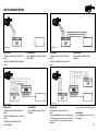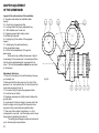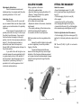
1
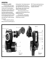
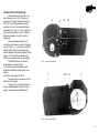
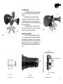
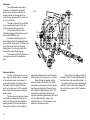
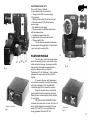
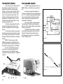
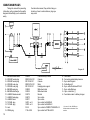
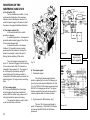
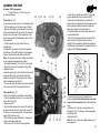
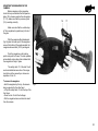
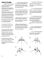
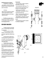
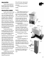
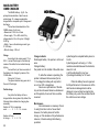
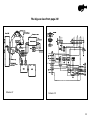
SOREMEC - CEHESS
Department “ECLAIR INTERNATIONAL”
41-45, rue Galilee - 75116 Paris
Tel: 723.78.56 +
Telex: 610 663 F ECLAIRE
Cable: ECLAIRCAM PARIS
2
Technical Characteristics
Weight:
4.3 kg without lens
Overall dimensions:
275 x 180 x 160 mm, without lens (11" x 7" x
6" 1/2)
Capacity:
pre-loaded 60 meter (200ft) or 120 m (400ft)
snap-on magazine
16mm film:
• double or single perforation
• A winding (emulsion out)
• B winding (emulsion in)
• on 50 mm (2 in) core-120 meter rolls
• on 30 or 60 m (100 or 200 ft) daylight loading spools
Climatic conditions:
Temperature - 20° C (4° F) to + 60° C (140°
F)
Humidity: up to 95% RH
Film Transport:
claw movement controlled by an excentric
and a fixed cam.
Reflex veiwing:
by a half-speed oscillating mirror.
Shutter:
plane type with a 175° opening.
Viewfinder:
for left and/or right eye, rotatabhle through
360° with image re-erected, dioptry adjustment
and eyepiece shutter.
Gelatine holder:
built-in and positioned between the C mount
and the reflex mirror.
Lens Mounts:
in C mount, screwed directly on the camera,
in Cameflex, Arriflex or Nikon mounts,
adapted to the camera by means of intermediate
mount.
Exposure indicator:
by 7 LED (light emmitting diodes) in vertical
display seen in the viewfinder.
Motor:
12 volts multiduty type, brushless, Hall effect,
6 crystal controlled speeds 8, 12, 24, 25
50, 75 frames per second. Automatic stop
in viewing position.
Power consumption:
from 0.8 to 1.2 Amps at 12 volts (20 C to 68° F)
Batteries:
12 volts MIBAC type: weight 0.640 gr (1.5 lbs)
(capacity 1.2 ah); rechargeable in less than
30 minutes equivalent to eight to ten 60 m
magazines or 12 volts BAKEL type:
weight 1.650 kg, capacity 4 ah equivalent
to ten to fifteen magazines
Noise level:
Quiet functioning that permits sync, filming
without any blimp.
Flat base:
standard 3/8"x16 threads per inch taping
for using a tripod or a polo stick.
Hand-grip:
adjustable lateral type with "ON/OFF"
micro-switch.
Standard screw:
on top of the camera for attachment
of accessories such as handle, boost lighting
mike support, etc.
3
DESCRIPTION
THE CAMERA HEAD (Code MIPEX)
The camera head (Fig A) in special
aluminum alloy supports the lens mounts (1)
in stainless steel, the interchangeable gelatine-holder (2), the reflex viewfinder (3), the
motor (6) with its control for electronics (7),
the electronic base (8) incorporating the
sliding on/off switch (32), the lateral support
(75) of the hand-grip (36) with its micro-switch
(76), the magazine lock release lever (16)
with its safery catch (17) and the removable
hand-grip (36).
On the rear (Fig B): the mechanism
plate (9) on which are mounted film gate (10),
2
the fixed guide bar (11) and its side pressure bar
(12), the magazine drive shaft (18), the 4 pin
power supply socket (19) for connection with the
battery, the clapper switch (20) and the potentiometer (34) of the exposure indicator.
Inside: the claw mechanism (13), the
oscillating mirror (14), the plane shutter (15) and
the exposure indicator unit.
The snap-on 60m, or 120m magazine
are attached onto the camera head as well as
the fixed focal or zoom lenses.
NOTA. The above camera head can be supplied without Exposure indicator unit; its
commercial code is MITAN.
29 30
3
17
16
9
10
1
14
75
76
32
11
12
13
6
18
7
34
19
20
8
Fig. A
Camera head front view.
Viewfinder positioned
for the left eye.
4
Fig. B
Camera head rear view.
Viewfinder positioned
for the right eye.
THE MULTIDUTY MOTOR (MIVAR)
This brushiess motor (6) has a very
high efficiency (from 0.8 to 1.2 amp. consumption at 12 volts to drive the camera at
20°C (68° F) and has permitted a weight
reduction not only in the camera but also in
the battery (37) - page 12 - which weighs only
640 grammes enabling one hour of filming
between recharges, i.e. eight to ten 60 m
magazines.
The incorporated electronics (7)
control the sync. speed by crystal ; changing
from 24 to 25 f.p.s. or vice-versa is made by
shifting switch (38) so that the white spot
mark is adjacent to the desired speed. Others
speeds : 8.12.50 and 75 are obtained by
setting the engraved button 35 accordingly.
The MIVAR will stop the camera
automatically in viewing position,
i.e. the mirror being in the aperture axis
allows the cameraman to frame and focus
without
loss of time. See pages 24 and 30.
The motor will only operate when it is
attached to the camera.
The lamp (47) on the motor lights up
until the marked speed is attained. In the
event of speed reduction (flat battery for
6
47
38
35
7
Fig. D. - Front part of the MIVAR.
7
38 35 47
6
Fig. E. - Rear part of the MIVAR.
5
THE 60 m MAGAZI N E
The two chambers of this snap-on coaxial magazine are separated by a median
partition and are connected by a light tight
ramp for the passage of the film from the feed
side to the take-up side (Fig F).
THE 120 m MAGAZINE
Bearing in mind the versatility and light
weight of the 60 m magazine which can be
changed almost instantaneously, there are
occasions where a « long take » in excess of
60 m is required and for this purpose a 120 m
capacity magazine is available.
This co-axial magazine retains all the
characteristics of simple threading and snapon action for which the Eclair equipment is
famous.
Fig. G
Fig. F
Fig. H
Fig. I
6
36
THE HAND-GRIP
The portability of the ACL is increased by
the use of the hand-grip (36) supplied with the
camera.
Adjustable in the horizontal and the
vertical plane, it permits the choice of the most
confortable position. It can be screwed either
under the camera base or on the right hand side
of the camera (fig K).
To carry the camera, the hand-grip (36)
with its knurled knob (79) - fig. QR - can also be
screwed on top of the camera head.
75
Fig. K
MOUNTS AND LENSES
The ACL has been designed to accept
« C » mount lenses (fig Q, the mechanical back
focal distance of which are 17.52 mm, and also
other professional mounts such as Eclair CA (fig
M) Arriflex, Nikon, etc... the mechanical back
focal distances of which are greater than 17.52
mm.
Fig. J
48 mm
Ca mechanical back focal distance
C mechanical back focal distance
17.52 mm
26
24
Film plane
25
Fig. L
Fig. M
Lens in C mount
Lens in CA Eclair mount
Fig. N
Intermediate mount
7
The mechanical back focal distances
(fig N) being different according to the professional equipment manufacturers 48 mm for
ECLAIR (Eclair CA), 52 mm for
Arriflex, 46 mm for Nikon, corresponding
intermediate Eclair TS mounts (Fig P-P’-P”-)
can be supplied for these different makes of
lenses for use with the ACL camera. For Arrif
lex, specify « normal mount » or « new steel
bayonet mount ».
Hence, the ACL lens support (1)
comprises an internal threading (21) the
diameter and the thread pitch or which correspond to the C lenses standards and an
external threading (22) for the Eclair TS
mounts (Fig P-P’-P”); the orientation of the
lens is ensured by the slot (23) at tfie top of
the flange.
Fig. P
Fig. P’
Fig. P’’
Intermediate mount
for lenses in CA mount
Intermediate mount
for lenses in Arriflex mount
Intermediate mount
for lenses in Nikon mount
ACCESSORIES
The principal additional accessories of an
“ACL” equipment are :
• The 12 volts battery type VR 1,2 Code MIBAC
• The connection
cable camera/battery VR 1,2 ............. MIBLE
• The rapid charger ............................... MIRAP
or
• 12 volts battery type VR 4 .................. BAKEL
• The connection
cable Camera battery VR 4 ............... BABAC
• The compact charger ......................... CIBRE
• The connection
cable Charger/battery ........................ COURE
• The pilotone module ........................... MODUL
• The connection
cable Module/recorder
(according to the make of the recorder)
• The transport case .............................. MALAC
8
23
21
1
22
Fig. O
GENERAL INFORMATION
REFLEX SIGHT
The reflex image is obtained with an
oscillating mirror (14) moving at half camera
speed, which transmits the image formed by
the lens onto the ground glass during the
descent of the film.
The viewf inder (focussing tube) is a
new mechanical /optical realization which
gives an exceptionally bright image.
As on the Eclair 16, the ground glass
gives a field of view greater than the recorded
image, which eliminates the possible intrusion
of microphones, etc... into the recorded
picture. (Fig Q).
This viewfinder - 10 x enlargement can be used for left eye or right eye viewing it
can pivot through 360' parallel to the camera
thus allowing the cameraman to frame and to
focus in the most comfortable conditions
whatever the position of the camera; for
example, he can shoot with his back facing
the subject. The eyepiece is adjustable of ±
5dioptres.
The standard ground glass is engraved with the 16 mm frame (10,2
x 7,4 mm), the TV frame and a cross in the
centre (UER standard).
Gelatine filter holder
Each ACL is equipped with a gelatine
holder 2 (Fig A and R) which is located between
the C mount and the reflex mirror close to the
rear element of the taking lens. Its advantages
are :
• It is not necessary to change filter at each lens
change.
• It is possible to check the presence and type of
gelatine through the viewf inder.
• It eliminates the requirement for front glass
filters for each lens diameter, the price of which
is very high compared to that of gelatine filters
which are readily obtainable.
27 2
Fig. R
• Its position, away from the fi I m plane ensures any small dust or finger marks on the
gelatine that may occur are out of focus on the
final result and rarely visible.
Shutter
Contrary to reflex cameras in which the
mirror mounted at 45' acts as a shutter, the
ACL has a plane shutter of large diameter
completely independant of the mirror (14). It is
placed very close to the film plane with an
opening of 175'. Cutting the image in the
direction of the smallest dimension gives a
perfect exposure, maximum definition and
reduction of jerky effect on some panning
shots. The exposure time is 1 /51 of a second
at 25 frames per second and 1 / 49 of a second at 24 frames per second (page 33).
+
0
Fig. Q
9
Mechanism
The complete silent mechanism is
mounted on the mechanism plate which
greatly reduces the time required for the
normal overhaul and cleaning which we
would strongly recommend to be carried out
by one of our agents.
The claw movement (13) is controlled
by an excentric and a fixed cam (39), the
security is ensured by a counter-cam.
The four drive shafts run in selflubrificated bearings and the camera mechanism should NEVER be oiled.
As already indicated page (4), the
aperture plate of hard chromium-plated steel
has, on the left, a fixed guide (11) which is the
edge reference for the film and a spring
loaded guide (12) on the right, which maintains the film against the fixed guide.
The two guides (29-30) fig B position
the magazine nose onto the mechanism
plate.
Exposure indicator
The ACL camera had to have a very
safe « Exposure Indicator device » because
of the professional work it must ensure. It
could not be question of an ordinary photocell system due to the fragility of moving
parts; on the other hand, a 100% automatic
device leaves the cameraman no change of
artistic creation.
The basic idea is to leave the cameraman freedom to determine the exposure of
the film and thus give him the possiblility of
working according to his own technique; in
other words he must have the possibility of
10
Fig. S
13
14
39
adjusting the diaphragm if he needs a special
effect by under or over exposure, e.g. contrast.
Before filming, the operator sets the
exposure indicator with the aid of his professional photo- cell exposure meter indicating the
diaphragm opening (stop) of the lens; it gives
him a reference lighting intensity « EO ». The
camera being connected to the battery, he
adjusts the sensitivity potentiometer (34) so that
only the middle diode EO, visible in the
viewfinder, lights up. Thus the camera is now
matched to the exposure meter.
During filming, if the lighting intensity of
the subject varies, the control diodes visible in
the viewf inder will be seen light up either + or . The operator wiII then correct the diaphragm
of his lens so as to maintain the lighting intensity on the film to a value of EO, if he deems it
necessary.
ELECTRONIC BASE 150 E
This unit (8) forms a flat base
for the camera body and consists of:
• 1 Jaeger socket (19) for power supply
to the camera.
• 1 Sliding on/off switch (32) at the front part.
• 1 Cannon socket (33) for the accessory
power supply.
• The stabilized 5 volt supply.
• 1 Souriau socket for electrical connections
with the camera head.
• 1 sensitivity potentiometer (34)
for adjustment of the exposure indicator.
• 1 Clapper switch (20).
This flat base is provided with the standard congress 3/8 tapped hole for tripod mounting or hand- grip mounting (36).
PILOTONE MODULE
34 19 20 8 33
Fig. X
Magnetic recorder side
Fig. Y
The ACL servo-control led crystal motor
allows the shooting of sync. sound without any
cable connection between the camera and the
tape recorder if the latter is equipped with a
crystal controlled motor (e.g. Nagra 4,
Perfectone E P 6 A2, Stellavox). Such a system
(diagram KL) does not permit the use of the
clapper.
If, however, the two units Camera and
recorder are connected by a cable, the clapper
will function (diagram L M). See additional
information page 29 for connection and use.
When the recorder has no crystal, the
synchronization can be ensured by using the
Eclair pilotone- module (option) which contains
its own signal.
THE ECLAIR PILOTONE MODULE is
contained in a metal cover. Its size: 92 x 66 x 23
mm is slightly larger than a packet of 20 cigarettes (fig. Y and Z). it is a crystal pilot f req
uency generator 50-60 and 100 H Z.
8
32
Fig. X’
Camera side
Fig. Z
11
THE BATTERY (MIBAC)
THE CHARGER (MIRAP)
The low torque ot the camera and the
high efficiency output of the motor have
allowed the construction of a low power
battery (1,2 amp-hour) which at 20°C (68°F)
provides power for ten 60 m (200 ft) magazines i.e. for about 600 meter of film. This
battery (37) weighs less than 1-4 lbs (640
grammes). It is a Saft type VIR 1.2 ten cell
cadmium-nickel which is enclosed in a polyurethane case (48) fig. AB.
The battery is equipped with a textile
shoulder strap although its small size will
allow it to be slipped into a coat or trousers
pocket.
The connections with the camera and
the pilotone-module can be made from either
of the Jaeger 4 pin-sockets (49). The central
Socapex socket (50) is provided for the rapid
charger.
CABLE. The same type of cable
(MIBLE) is required for connecting the camera, the battery and the pilotone-module. It is
fitted with two Jaeger plugs ref : No 530800.
Our V.R. mini-cell battery has been
conceived for a recharge in less than 30
minutes by means of our MIRAP charger
connected to the mains between 115 and 220
volts A.C.
The MK2 charger specially made for our
MIBAC battery is automatic and very simple to
use.
It ensures a charge feed regulation of
± 20 % for a variation of the main supply tension
of ± 10 %. It stops the high speed automatically
as soon as the battery has attained a tension
which is related to the charge rate and the
temperature of the battery.
The cut-off precision is approximately 1
Immediately after the high speed charge has
been cut-off, the charger switches automatically
to the low charge rate.
The thermostatic protection is ensured
by a thermal limiting device which cuts off the
charge if the battery temperature becomes
abnormaly high e.g. because of irregularity in
the cut off safety circuit
Diagram CD
48
Diagram DE
Fig. AB
12
49
50
49
37
Fig. BC
BATTERY (BAKEL)
CHARGER (CIBRE)
If a battery having a larger capacity
than the MIBAC battery is desired, especially
if the camera is often used at higher speed
than the standard, we can supply the BAKEL
battery (of the Eclair NPR 16) type VR 4 (4
amp-hour). It is a 12 volts cadmium-nickel
battery - Fig EF - with a discharge controller
(Schoeller galvanometer) and is supplied in a
plastic box made of unbreakable black polyethylene with a carrying textile belt.
It is composed of 10 insulated cells
SAFT type and weighs 1,650 kg; its dimensions are 230 x 150 x--40-mm and its capacity is equivalent to ten to fifteen 120 m (400 ft)
reels. Its use necessitates a connection cable
« Camera/ Battery » (BABAC), a 220/110 v 12 V charger (CIBRE) and a connection cable
« Charger-battery » (COURT).
The BAKEL battery can be also suppl
ied in a leather belt with built-in charger, its
code is BACHA. Its weight 2.750 Kg; only the
connection cable « Camera/ Battery »
(BABAC) is necessary.
The new compact charger CIBRE type
76 is very smal I : 125 x 64 x 40 mrn and
weighs only 420 grammes.
An internal tension selector permits its
utilization on 220 or 110 volts; safety is ensured by a 500 mA fuse. A 2 metre connection cable « Main/Charger » is supplied.
The CIBRE charger bears, at one end,
a 3 pin socket (mains side) and at the other
end a 4 pin Amphenol socket for connection
to the battery; two control lamps : one red and
one green light up as soon as the charger is
connected to the main. The green light cuts
off when the load is over.
The select the voltage in the charger
(110 or 220 volts) or to replace the safety fuse,
unscrew the 4 screws of the lid ; take- off the lid
without dropping the screws, select the tension
or replace the fuse, put the lid back and tighten
the screws.
Fig. EF
Fig. GH
Fig. FG
CARRYING CASE
Made in shape of a rigid suit-case(fig
GH) and not like an ordinary transport case, the
framework is anodized aluminium supporting
two shells in ABS which is a very high impact
resistance material. The inside is entirely padded with expanded polyethylene cut out to the
form of a complete ACL equipment : Camera
with motor, viewfinder and 60 m or 120 m
magazine mounted, extra 60 or 120 m. magazine, battery, charger, cables, pilotone module
and miscellaneous (fig. HI).
Fig. HI
13
CABLES AND PLUGS
Taking into account the preceding
information, will you please find hereafter
diagrams that will help you to understand
easily
the instruction manual; they will also help you
should you have to order cables or plugs you
may need.
Diagram JK
1 - JAEGER female socket
2 - CANNON female plug
3 - CANNON female plug
4 - CANNON male plug
7 - CANNON male plug
8 - JAEGER male plug
9 - JAEGER cable flange
10 - JAEGER female socket
11 - JAEGER male plug
12 - JAEGER cleat
13 - TUCHEL plug
14 - TUCHEL plug
15 - Jack
16 - PREH plug
14
533800
MDB 19 SH 031
MD 19 SH 031
MDB 19 PH 031
MD 19 PH 031
530800
530332
533272
530273
530371
3401/1 ou /2
3300/1 ou /2
PL 55
7140-4-250
Camera-battery-module
Camera
Camera
Motor
Handgrip side support
Mible feed cable
Mible feed cable
Module
Sync. cable
Sync. cable
Sync. cable for NAGRA III
Sync. cable for NAGRA IV
Sync. cable for PERFECTONE EP6 A II
Sync. cable for STELLAVOX
A - Feed cable
B - Connecting cable battery/camera
C - Sync cable Nagra iii
D - Cable Nagra IV
E - Sync. cable Perfectone EP6 A II
F - Sync. cable Stellavox
G - Sync. cable Uher (*)
H - Feed cable mains to battery charger
(*) In case of « Uher 1000 Report »
recorders state serial number of the
machine.
UNITS CONNECTIONS
Schema KL
Equipment
• Camera with crystal controlled
motor
• Recorder with crystal controlled
motor
Schema LM
Possibilities
Sync. without connection cable
No clapper
Possibilities
Sync. with connection cable
Clapper
Schema NO
Schema MN
Equipment
• Camera with crystal controlled
motor
• Recorder with crystal controlled
motor
• Pilotone module fed by the
camea battery
Equipment
• Camera with crystal controlled
motor
• Recorder with crystal controlled
motor
Possibilities
Sync. with connection cable
Clapper
Equipment
• Camera with crystal controlled
motor
• Recorder without crystal controlled motor
• Pilotone module fed by an external power
supply: MIBAC 12 volts battery whenever
possible
(shunt 3 and 4 by the Jaeger plug)
Possibilities
Sync. without connection cable
No clapper
15
16
INSTRUCTION MANUAL
When you receive your equipment for
the first time we recommend you examine
every unit individually in accordance with the
information given in this brochure.
After that, you will be able to follow the
instructions for use more easily.
MOUNTING A “C” LENS
• Remove from the camera the protective cap
of the lens mount.
• Remove from the lens the cap protecting the
thread.
• Remove any dust from the flange with your
finger.
• Screw in the lens in 21. Fig. 0.
If the distances and stops engraved
on the lens barrel cannot be read by the
cameraman in the normal operating position :
take the lens off the camera.
The threaded ring at the bottom of the
lens is mounted in contact with a special
spring washer. Without touching the rear lens
element, press down firmly on that threaded
ring and turn it to modify the orientation of the
distances and stop marks with respect to the
thread start.
2nd PART -
MOUNTING AN ECLAIR “CA”
MOUNT LENS
• Remove the protective cap and the guard ring.
• Remove any dust from the flange with your
finger.
• Locate the intermediate TS-CA mount (fig. P)
on the lens support plate ensuring that the
locating pin (24) enters the slot (23) of the
flange.
• Screw up the retaining ring (25).
• Position the lens so that the slot (26) in the CA
mount is vertical. 9 Push the lens into the TS
intermediate mount and lock by turning the lens
clockwise.
As you will notice the Eclair intermediate
TS mount is exceptionally robust with a large
locating diameter and thrust face. The use of
lens supports with the mount is not necessary.
It is strongly recommended that each
zoom lens is fitted with an intermediate TS
mount to prevent the deterioration of the limit
stops on the lens after repeated locking in place
on the camera.
17
DIOPTRY ADJUSTMENT
OF THE VIEWFINDER
Legend of the external parts of the viewfinder:
Ll - Eyepiece with shutter and rotatable rubber
eyecup.
L2 - Control ring of eyepiece shutter.
L3 - Locking knob of the dioptry adjustment ring.
L4 - 360' rotatable viewf 1 nder unit.
L5 - Eyepiece support with rocking motion
for left and right eye sight.
L6 - Locking ring of the rotation of the eyepiece
support.
L7 - Adjusting ring for partial positioning
of the ground glass image.
L8 - Clutch for final adjustment of the ground
glass image.
Everyone having a different keenness of sight, it
is necessary for the camera user to set exactly and then
lock the dioptry adjustment which corresponds to his
vision. This can be done with or without lens mounted
on the camera.
Adjustment with a lens:
1. Place L5 to the right or to the left according to the eye
you normally use.
2. Make sure that the reflex mirror is in the front of the
aperture, if not, turn knurled button 31 which controls the
motor axle (see page 24, par. 5)
3. Turn control ring L2 to open the eyepiece shutter.
4. Focus the lens on infinity.
5. Diaphragm wide open or slightly closed to darken the
ground glass.
6. Loosen knob L3 and turn slowly in one way and in the
other the dioptry control ring until the frame and cross
engraved on the ground glass are perfectly sharp.
7. Take note of the number of dioptries in + or - that
corresponds to your sight. Lock the dioptry control ring in
that position by tightening the button L3.
This setting should always be kept as it will permit
you to focus sharply at any distance.
18
Fig. PQ
Adjustment without lens :
Direct the camera towards a well
lighted part (sky, for example) and follow the
preceding instruction 1-2-3-6- and 7.
Instruction for use
Position L5 for your left or your right
eye, as needed. Make sure the dioptry adjustment is correct and the button L3 is perfectly
tightened.
If the image on the ground glass is not
optically horizontal, turn ring L7 in one way or
the other to level the image. If you.come to
the thrust before the image is in the right
position, turn L8 in the reverse way and move
again L7. Once the image has been so
erected the viewf inder can be pivoted
through 3600, a Wollaston prism will keep it in
the correct position.
If you shift L5 from left to right or viceversa the image will reverse gradually until it
is up side down; just turn L8 to declutch L7
and turn same to reset the image to its normal position. A positioning "clic-stop" is
provided in L6 to set the eyepiece Ll in horizontal and vertical positions.
GELATINE HOLDER
FITTING THE HANDGRIP
Fitting a gelatine to the holder
• Pull out the gelatine holder
• Open the holder by pressing the button (27)
• Place a 2" margin (5Ox5O mm) gelatine
in the holder and close it.
• Cut the gelatine closely to the shape
of the holder with a razor blade.
• Replace the holder in the camera, chamfered
side forward.
• The correct positioning of the holder can be
verified by checking that the aperture
is concentric with the C mount aperture.
Under the camera :
• Screw the handgrip support - Fig. QR into the electronic base using the knurled
ring (27)
• Fix the handgrip (36) in the hole (80)
of the support.
• Loosen the ring (79), set the position
of the handgrip and tighten the ring (79).
• Loosen the half-moon (81), set the handgrip
at the desired angle and retighten lock (81).
Onto the right hand side of the camera:
• Fix the handgrip (36) to the side support (75)
and lock it in the best position by means of lock
(81).
NB. Never place more the one gelatine in the
holder.
Always film with the holder in place (with
or without a gelatine) to avoid the possible
fogging of the film.
The fact of filtering behind the rear
element of the taking lens may cause a slight
alteration of the focussing distances engraved
on the lens which will be automatically compensated if focussing is done through the reflex
viewfinder.
NB. The unit (79-80) - Fig. QR - is not used in
this case.
Fig. RS
Fig. QR
81
36
Fig. ST
79
77
75
76
80
82
77
78
19
FUNCTIONS OF THE
ELECTRONIC BASE 150 E
a) On/off switch (32)
This is a double action switch : it puts
under tension the diodes of the exposure
indicator, without starting the camera. Or it
sends the power supply to the motor to start
the camera. tee page 24 detailed instruction.
b) The clapper switch (20)
In the central position this switch
provides no clapper.
In outside right position : the clapper is
automatic and provides fogging of the film for
0,3 secondes at each start.
In inside left position : the clapper
functions (0,3 seconds) at every manual
pressure when the camera is running; this
allows, for example, to clap at the end of
filming, before switching off the motor.
Schema UV
32
Thus, the clapper ensures two functions 1 0 - Automatic fogging of the film during
0,3 seconds at each start of the camera or
manually at any moment. 20 - The supply of
an 8 volt signal to the battery during 0,3
seconds (bloop) if the pilotone module is
connected to the battery and the recorder, the
signal triggers a 1 Kc signal on the recording
tape.
c) The running signal:
A 12 volt signal available from the Jeager
socket supplies the pilotone module and
ensures that the module only produces a 12
volt signal when the camera is running.
This signal can also be used to start a
sound recorder from a distance.
20
Fig. TU
d) The output signal :
1 - Tachometric signal
This 3,8 volts square signal (peak to
peak) is supplied by the motor. Its frequency is
given by the motor speed multiplied by 40, that
is to say 1000 Hz for 25 images per second and
960 Hz for 24 images per second. This signal
directly supplied by the motor can be used for
various purposes after it has been divided.
2 - Crystal signal (for MIALA motor only) :
This is a 100 mV sine signal (peak to
peak). Its frequency is 1024 KHz for 25 frames
per second and 983.04 KHz for 24 frames
persecond.
Schema VX
To see the
big-ass view
go to page 35!
LOADING THE FILM
60 meter (200 ft) magazine:
To load a film on a 2" (50 mm) core,
proceed as follows:
Feed side (fig. XY)
(to be done in a dark room or in a changing bag)
• Put the magazine on its side, nose to the left.
• Depress the safety lock button and turn the lid
catch anti-clockwise; lift the part of the latch that
projects over the edge of the magazine. At the
same time pull the lid backwards to clear it from
the magazine.
• Lift the counter arm (53) which locks up
utornatically.
• Holding the film reel in the left hand position,
feed the end of the film (about 30 cm) between
the two rollers at the entry of the guide (54).
Note: the emulsion must be towards the exterior
of the magazine between these rollers.
• Push approximately 15 cm (6") into the guide.
• Place the core onto the support f lange (55).
• Replace the Iid:
insert the spring strip, at the left of the lid, into the
magazine body (56), push the lid down and
forward to locate it in the body and turn the lid
catch clockwise to lock the lid.
• The counter arm (53) drops into place automatically as its catch (57) is released by the Iid.
Take-up side (fig. YZ)
(this can be loaded in, preferably in the shade)
• Turn the magazine and lay it on its side with the
nose (58) to the right.
• Remove the lid.
• Pass the film between the rollers (59) and (60)
and place the end into the upper film guide (61)
of the nose; if necessary press on the pressure
guide (62) to aid the entry.
• Pull the film through sufficiently to introduce it
into the lower film guide (63).
• Pull 50 cm (20") of film into the magazine.
58
73 72
57 53
56
• Open the two guide shoes (64-67) by pressing simultaneously the two catches (65).
• Place the film behind the two rollers and
between the sprocket (66) and the upper guide
shoe; make sure that the sprocket teeth are
perfectly engaged in the perforations.
• Close the upper shoe toward the sprocket; it
locks automatically.
• Place the film between the sprocket and the
lower shoes (67); adjust the loop size by
pulling the film upwards outside the magazine
until the loop is level with the magazine locking
tongues (68). This is important.
54
74
59
60
65
55
61
68
62
64
69
66
67
65
S
63 58
• Close the lower shoe (67) against the s
procket and divide the film equally over and
under the film separator (69) in the magazine
nose.
• Wind the film onto the core and place it on
the flange (70). This flange is interchangeable
with flange (55).
• Replace the Iid.
Note: the « S » part is an audible warning unit
(see page 25).
21
Loading a daylight loading spool
to the magazine
• Choose a shaded area if possible.
• Pull and lift vertically the flange catches (71)
on the supply and take-up sides.
• Remove the flanges (70).
• Load the film as for a core load.
• Lock the spools in place with the catches
(71) ensuring that they are pushed firmly
home.
NB. In order to ensure the lowest noise level
check that the spools are not warped and that
they are firmly locked onto the axle as indicated above.
If it is not intented to use the magazine
at once, place the protector on the nose.
The counter (72)
As already noted, the counter arm
comes into operation automatically. The
pointer (73) indicates the amount of unexposed film remaining; a red portion of the
counter dial indicates the imminence of the
end of film.
Take-up side (fig. AC)
• Put the magazine, flat on a table, nose (58) to
the right.
• Take-off the lid as per the supply side.
• Load the film as per a6O rn magazine.
Note - The same recommandat ions for the fiIm
loop must be applied.
Footage counter :
As in the 60 m magazine, the counter
arm comes into operation automatically. Outside, on the feed side, two dials engraved in
meters and in feet move in front of a guide
mark and respectively indicate the amount of
unexposed film used : either a 120 m reel on a
50 mm core or a 60 m daylight spool.
Fig. ZZ
70 (55) 71
83
58
120 m (400 feet) magazine:
Loading the 120 rn magazine in dark
room on a 2" (50 mm) core:
Supply side
• Place the magazine, flat on a table, nose
(58) to the left.
• To remove the I id, press on button (83) and
turn downwards the white lock (84) for about
20 mm.
• Lift slightly the rear part of the lid and pull it
to the right to disengage the spring which
maintains the front part of the I id to the nose.
• Load the film according to the information
given for the 60 rn magazine.
22
Fig. AC
84
MOUNTING THE MAGAZINE ON THE
CAMERA:
Before snapping on the magazine,
check the loop and ensure that the aperture
plate (10) is clean as well as the side guides
(11-12), make sure that the pressure guide
(12) is working correctly.
16
17
Make sure also that the outside loop
of film is equalized (up and down) in front of
the gate.
With the magazine tilted backwards
(fig. G) place the lower part of the magazine
nose at the bottom of the aperture plate, the
magazine drives shafts (18-74) are aligned.
Pivot the magazine on its locating
points and push it at home. The lock operates
automatically and a sharp click indicates that
the magazine is firmly in place.
The safety catch 17 of the lock 16 will
avert accidental disconnection of the magazine that could be caused by a chance manipulation of lock 16.
To remove the magazine:
• Hold the magazine by the top, the camera
being supported by the other hand.
• Lift up the safety catch 17 with the top of the
fore finger.
• Press on lock 16 with the forefinger.
• Pull the magazine down and back to clear it
from the camera.
Fig. G
23
STARTING THE CAMERA
Having fitted a lens and the magazine
on the camera and checked the dioptry
adjustment of the viewfinder:
• Attach the battery to the camera with the
cable MIBLE (or with the cable BABAC if you
are using a BAKEL battery).
• Make sure that the motor has been set at
the right speed : for 24 frames per second,
move the switch (38) to the right so that the
white spot will be in front of 24. Turn the knob
35 so the letter N faces the datum mark. For
25 f.p.s., move the switch (38) to the left to
have the white spot in front of 25; the knob 35
should be placed as indicated above, i.e.
« N » in front of the datum mark.
• For other speeds : 8-12-50 and 75 f.p.s.
place the desired speed engraved on the
knob 35 in front of the datum mark.
• Frame and focus through the viewfinder. If,
by chance the reflex m 1 rror is not in the
viewing position, adjust-it by turning the
knurled knob (31) anti-clockwise. Normally,
the MIVAR motor always stops the camera in
viewing position (page 5 par. 3).
• Set the clapper switch to the required
position : central : no clapper right : automatic
clapper at each start. manuel clapper is
operated when the switch is moved to the left
(see page 27).
Start the camera by pushing the button
(32) in and sliding it to the left-position-3- (towards the motor) or by moving the side microswitch 76 upward after the button 32 has been
pushed to the right- position 2-.
• The stop in viewing position (shutter in front of
aperture) is automatically obtained if the microswitch 76 has been used. It is also obtained if
the switch 32 is brought back from position 3
« run » to position 4 « stop ».
• When the camera has been stopped by the
switch 32, from position 3 to position 1, the
reflex may not completely cover the aperture;
turn knob 31 anti-clokwise.
• When the camera has been stopped, the
warning light 47 on the motor body remains lit a
few seconds and then goes out. It this lamp
lights up during f liming, it indicates the battery
is flat or motor is out of phase.
Pos. 1. The switch (32) being in central
position is « off » position. When depressing
the button (test position), the exposure indicator is put under tension and the LED diodes
light up.
Pos. 2. When sliding the switch (32) to
the right, (looking though viewfinder) the test
position is retained (camera stopped) for
determination of the diaphragm stop.
The starting and the automatic stop in
viewing position can be obtained by the switch
76.
Pos. 3. The switch 32 being slid to the
left starts the camera and the LED remain
illuminated.
Pos. 4. The switch 32 being slid back to
the right, the LED remain illuminated the
shutter wi ll stop in viewing position.
1°
2°
3°
4°
Fig. CE
24
It is important to resume the 4 functions
of the switch 32 on an ACL equipped with
electronic base 150 E incorporating the Exposure indicator.
Audible warning device in magazine:
This system S (fig. YZ) also called
« ghost indicator » functions if the film loop is
resorbed; it produces a clicking sound which
warns the cameraman.
In that case :
• Stop the camera and remove the magazine.
• Check the loop and divide it normally.
• Re-mount the magazine on to the camera.
• Restart the camera.
Should this occur again, check in a
changing bag the threading of the magazine;
you will probably find a film jamming due to
some damaged perforations.
Characteristics
• Type of photometer: to adjust by comparison
manual setting of aperture ring.
• Type of measurement: behind the lens (T.T.L.)
semi-spot 4 mm dia, angle 100 with F. 25 mm
semi- spot 7 mm dia, balanced at 50%.
• Sensitivity range: 25 to 400 ASA.
• Sensing element : rapid response C D S cell.
compensated sensitivity range.
• Display: 7 Light emissive diodes (LED) resolution interval, 0,5 dia/1 dia/1.5 diaphragm.
• Light computation : resolving prism (= 25 % on
the CIDS cell) neutrallsing the semi-reflective
deposits.
• Compensation Stop-go: electronic compensation; automatic compensation.
Diodes LED
EXPOSURE INDICATOR
This being temperature compensated
(-25° to + 60°C) the setting remains constant
for several weeks.
The measuring system and display
assembly is situated immediatly next to the
ground glass, supporting the viewfinder frame
(fig. T).
A resolving prism (01) which is semiref lecting is stuck to the prism block (02) and
ref racts part of the I ig ht rays emerg 1 ng
from the ground glass towards the photo
resistive element (03).
The light intensity received by the
photo resistive element is compared with the
reference determined by the gauge, and
intensity already memorised by the computer
(fig. U).
The seven diodes are mounted on a ceramic
base situated next to the ground glass,
outside the field of view (fig. T); they indicate
the zero or the difference in aperture (either +
or The maximum recordable difference is ±
1.5 stops, each diode representing about one
half stop (fig. U).
Fig. U
03 01 02
Fig. V
04
reflex
viseur
Fig. T
25
Advantages of the system
• Compactness of the measuring assembly
and display situated next to the ground glass
This lay out requires the minimum of optical
components, no reflection, no intermediate
optics, (no risk of misalignment).
• System of setting up by comparison
No setting imposed by the manufacturer, the operator is the judge of the optimum
fighting for the film.
No variable density disc, no compensation for non-linearity of the CDS cell
respose.
No corrections to be made on the
sensitivity adjustment in spite of ageing and
the history of the CDS cell.
• Application of LED:
Unlimited life for the whole unit (even
when subjected to heftier shocks that is likely
to occur to the system during transportation)
No Iight reflecting device to be indicated by a lively balanced pointer. Constant
light emission from the L.E.D.'s.
• Seven diodes : one central zero and six
indicating + 0,5 stop, 1 stop, 1 .5 stop
- 0,5 stop, 1 stop, 1.5 stop
• Progressive lighting up of the diodes (one,
two, three) ensures a positive indication of
difference in exposure.
26
INSTRUCTIONS FOR USE:
1° Setting up:
• Connect the battery to the camera.
• Look in the viewfinder to make sure the camera is in viewing position (mirror in front of
aperture).
• Move the switch (32) to the right. The diodes
will light up (camera stopped).
Determine with your. light meter, the
setting of your diaphragm taking into account
the speed of the emulsion and the filming
speed.
• Adjust your lens according to the setting
indicated by your light meter (f. 5.6 for example).
• Looking through the viewfinder, turn with one
finger of the right hand the sensitivity potentiometer 34 one way or the other so that only the
central diode lights up. This being done, your
camera is now set up.
2° Filming
Obviously, for keeping a normal exposure, the central diode only must be lighted. If
the lighting intensity of the object varies, the
control diodes will be seen lit up either + or -,
visible in the viewfinder; this will indicate that
you overexpose or underexpose. The operator
will then adjust his diaphragm by closing or
opening it accordingly to come back to the
normal exposure which will be shown by the
illumination of the central diode only. In effect
the operator has a continuous indication of light
variations to within plus or minus 1 1/2 stops
from the normal exposure and which he can
vary at will (eg. for contrast effects).
MIBAC BATTERY
To plug in a Jaeger plug simply turn
and push the plug onto the socket until the
locking ring clicks into place. To remove the
plug, pull on the ridged ring.
MIRAP BATTERY CHARGER
It might be useful here to give a simple
outline of the operation of the rapid charge
system : when recharging a battery with a
current in the order of C 5 Amps a clear and
reproducible increase in voltage becomes
apparent towards the end of the charge,
whatever the initial level of charge of the
battery. It is thus possible to cut off the high
charge rate and pass automatically to the low
charge rate (the voltage increases as the
charge rate increases) and also the temperature of the battery (the voltage increases as
the temperature descends).
It should be noted that the most
favorable charge rate for the ACL battery is 2
C 5 A and that a recharge can be accomplished with a battery temperature between 20° C and + 40° C. The batteries are
equipped with a group of silicon diodes in low
series resistance and this system compensates for variations in temperature which
might otherwise affect the charge cut-off
voltage. The graph DE page 12 represents
the law governing the variation in charge cutoff voltage with respect to temperature. The
capacity obtained after a high speed charge
is very satisfactory (500 cycles 800 mAh) but
does not give the maximum possible capacity
which can be obtained by proceeding the
charge at a lower rate.
The MIRAP charger is provided with a
switch permitting the choice between the
rapid charge FAST (red diode) and the slow
charge SLOW (yellow diode).
At the end of the charge, it passes automatically on the maintenance charge TRICKLE
(green diode).
The slow charge increases the life of
the battery.
Operation
Plug the cable into the socket (51) - fig
DF - at the rear of the charger taking care to
position it correctly for the corresponding
voltage : 117 volts or 220 volts A.C. 50 cycles
or 115 volts AC 60 cycles. Plug the other end
into the power supply using a plug corresponding to the mains supply socket. This
connecting cable is provided with an earth
wire which is yellow/green in compliance with
the international standard.
Insert the battery into the charger, the
red point on top facing the red point which is
on the charger. If the battery is correctly
pushed in place, its plug (50 - fig AB -) enters
the socket of the charger and the control lamp
lights up. The charge will not take place if the
two red marks do not coincide. - fig EG -.
The consumption is 11,3 Amp at 220
volts.
When the battery is fully charged the
signal lamp will go out.
The ensemble -charger/battery- may
be left indefinitely connected to the main,
without any danger. On the other hand, never
leave a battery in the charger if the latter is not
connected to the main because the battery will
discharge.
A safety fuse 52 of 800 milli-amp.
protects the charger; it blows in case of excessive voltage increase. Two spare fuses are
stored in the two rear feet of the charger
-fig FH -
Fig. DF
51
52
Spare
fuses
Signal lamp
Red points
Fig. EG
Removable feet
Fixed foot
Fig. FH
27
BAKEL BATTERY
CIBRE CHARGER
The BAKEL battery - fig GI - the
principal characteristics of which are described page 13, is always supplied discharged after a complete cycle of charge and
discharge.
The technical characteristics of the
CIBRE charger -fig HJ -are:
• Dimensions: 125 x 64 x 40 mm
• Power supply :115 or 220 volts AC by
voltage selector, 50 or 60 cycles. 9 Weight:
0,420 kg.
• Safety : fuse on the alterning current, type
01 0,25 amp.
• Rate of charge : 320 mA.
Charge
According to the mains supply 115 or
220 V., connect the charger to the mains by
means of the cable; the two indicator lamps
light up.
Connect the 4 pin Cannon sockets of
the battery to the charger by means of the
CICAB cable.
Charge for 14 hours.
The green indicator lamp goes out at
the end of the charge.
Partial charge
Very often the battery will be recharged before having been fully utilized; the
following table indicates the charging time
necessary :
Number of 120 m magazines
used ............ 2 3 6 12 or more
Number of hours
of charge ..... 3 6
28
8
16
CIBRE
BAKEL
Fig. GI
Charge indicator
Discharged battery : the pointer is in the red
area.
Charged battery:
the pointer is in the middle of the white area.
If, while the camera is operating, the
pointer is between the two areas (for an
11.5 voltage) the battery will only last for
one or two 120 m magazines.
Never use a part section of the battery as the cells would become unbalanced
and the polarity of some of them could be
reversed.
Maintenance
No maintenance is necessary. Check
to wiring from time to time. Never alter it.
However, if a battery does not hold its
charge, or if the duration of its performances
reduces, it should undergo the following
operation:
Fig. HJ
a) discharge the complete battery down to
9 volts.
b) discharge each cell using a 1 -Ohm
resistance inserted between the terminals,
down to 0 volt.
c) let the cells stand for one hour.
d) recharge the battery for 18 hours.
If then the battery has not regained
its full performance it is because one of the
cells has been damaged and must be
changed. A new cell can be inserted into
the battery only under the condition that all
the cells have a zero voltage.
ACCESSORIES
PILOTONE MODULE
As already said, this accessory is a
5
crystal pilot frequency generator
50-60 and
100 hz. Its precision is ± 510 within a temperature limit of - 20° C to + 60° C (- 4° F to
+ 140° F). The output tension is 1 v. effective.
A three position switch 50-60-100
selects the pilot frequency recorded on the
magnetic tape corresponding to the standard
used when transfering the sound to 16 or
35 mm perforated film.
Our pilotone-module provides two
possibilities :
1. If the clapper is required connection
by cable (diagram IVIN) of the image units
(camera/ battery) to the sound units (recorder/ pilotone module), the MIBAC camera
battery supplies the pilotone module. The
cable allows the operation of the pilotone
module when the camera is running and the
recording of the « bloop » information on the
magnetic tape. This associates the crystal
generator regularity with the automatic clapper advantages.
2. If no clapper is needed: working
without a connection cable between the
image units and the sound units (diagram
N.O.). In this case, supply of the pilotone
module must be ensured by a second MIBAC
battery, the first one feeding the camera.
GELATINE HOLDER WALLET
Designed for five gelatine holders (in
supplement to that in the camera and the two
included in the standard handgrip) the wallet
gives the possibility of having a set of f i Iters
to cover conditions that.might be encountered
during filming.
MAINTENANCE
RECOMMANDATIONS
If there are deposits in the gate (10)
(channel) particulary along the side pressure
bars, remove them carefully with a tooth pick or
preferably a manicure orange stick. Never use
any metal object.
It is important that the spring load pressure guide (12) and the pressure plate of the
magazine (62) operate smoothly and freely. If
they do not work satisfactorily the equipment
should be returned to the supplier for adjusting.
Avoid the use of brushes since they are
generally dirty and have loose hairs. If a hair is
caught in the claw slot it may damage the
movement; if it is caught in the aperture it will
very likely appear on the projection of the film.
Using a clean chamois leather occasionally moistened a small amount of alcohol
clean the plate, rubbing up and down. Care
should be taken not to catch the claw (13) with
the chamois.
CLEANING THE MAGAZINE
AFTER SALES SERVICE
As all cinematographic equipment for
professional users, a general overhaul carried
out from time to time by the maintenance
service of your supplier will avoid troubles and
waste ot time and money.
The spare parts catalogue N * 7011
shows the ACL in the form of exploded diagrams that illustrate the location of all the
components that go to make up the camera,
motor and magazines.
INSPECTION AND REPAIR
TOOL KIT
A full set of tools is available for the
work necessary to keep the ACL in tip-top
condition.
The catalogue NO 7011 and a maintenance booklet are available, on request, to all
users who have at their disposal a repair
workshop for the cameras.
The sprocket drum and the pressure
plate roller-guides may be cleaned with a fluff le
cloth slightly moistened with alcohol. For the
interior it is preferable to use an air syringe.
For the optical parts use an air syringe.
Any other cleaning, even with optical or above
all tissue paper, could slightly scratch the surfaces.
29
CHANGING THE MOTOR
If you must replace your motor, please
proceed as follows
Removal:
• Disconnect the battery from the camera before
this operation is carried out.
• Take the lens off the camera.
• Turn the knurled knob 31 to bring the reflex
mirror in the aperture centre. In this position the
screw 46 of the knurled knob 31 of the motor is
adjacent to the guide mark engraved on the
motor casing - fig IK -; this position vertically the
two driving spigots 42 of the motor - fig JIL - and
the two corresponding holes of the camera rubber
driver (41) - fig KM -.
• Undo the three captive screws (40) with a screwdriver or a coin and pull the motor out along its
drive axis.
NOTE. For checking purpose, the bottom
screw (40) is sealed. Take the seal off with a small
screwdriver or a small pointed tool to allow access
to the screw.
46 31
Fig. IK
47 38 35
46
38 47
41
Replacement
• Make sure that the screw 46 of the knurled knob
31 is perfectly in line with the guide Q mar and
that the ref lex mirror is in the centre of the aperture.
Align the camera plug (44) on the motor
with its socket (45) on the camera and push the
motor into place along its drive axis - fig JL and
KM-. The two drive spigots (42) on the motor
must be perfectly in place in the two holes of
the camera rubber driver 41.
• Tighten the three screws 40.
• Check that the drive is correctly engaged by
turning the knurled knob (31) anti-clockwise. It
should run ireely.
• Re-connect the battery.
30
Fig. KM
Fig. JL
44
42
43
45
RECOMMENDATIONS
FOR USING OUR CAMERAS
UNDER EXTREME CLIMATIC
CONDITIONS
FILM AND TEMPERATURE
Storage
The package in metal cans conserves
the sensitometric and mechanical characteristics of the f ilm (raw stock material). On the
following table, we indicate the maximum
temperatures for storage not exceeding a
period of 6 months.
Black & white negative film 12° C = 53° F.
Black & white positive film
18° C = 64° F.
Color film
10° C = 50° F.
Lower temperatures would not entail
any inconvenience. The desired temperature
will be reached faster under cold climatic
conditions.
Bringing the film to shooting temperature
Before opening the cans bring the
film to « location temperature ». The following
table indicates in hours the time necessary to
compensate the temperature differences.
Temperature
15° Centig
difference
59° F
Relative
humidity rates
70°
90°
Insulated 16mm can 1/2
1h
Insulated 35mm can 1 1/2h
3h
Cardboard 16mm & 18h
36h
35mm
30° Centig
86° F
70°
1h
3h
36h
Cold. If a film has a too high temperature
under cold climatic conditions, it dries up
rapidly and becomes brittle. Cracks can
occur near the loops and the sprocketlwheels.
90°
2h
6h
72h
Heat. If a film has a too low temperature, in hot
climates, it is susceptible of condensation on the
surface; as a result the emulsion becomes soft
and sticky that leaves in the camera gate emulsion deposits which result in scratches and film
jammings.
Exposure
The sensitivity of cinematographic films
is conserved to - 20° C (4° F) and one would
have to reach a temperature of - 55° C (- 67* F)
for obtaining a loss of the diaphragms sensitivity.
In summary:
• Keep the film at indicated temperature.
• Avoid unnecessary temperature variations.
• Make sure that film-cans have shooting temperature.
• Do not leave the film in the camera more than
necessary.
• Develop the film as soon as possible.
HOT CLIMATES
Tropical and equatorial climates
The characteristics of these climates are
high relative humidity passing 70 % associated
with temperature of 30 a C (86 OF). We
(ecommend to transport cameras and films in
carrying-cases containing dessiccating agents
(moisture-absorbing product). If the carryingcases are not suff iciently water-vapor proof use
air-tight plastic-bags.
ECLAIR put these desiccatives in the carryingcases; keep them as they can be reused indefinitely. Just expose them at a temperature of
120° C (248° F). The humidity which saturates
the atmosphere is condensed when the temperature falls slightly; before sun-down put the
material into the transport case and never leave
the film in the camera over night.
Desert climates
The characteristics are very high
temperatures during the day and chilly nights.
As a result it is essential to use isothermic
containers to protect the film from these temperature variations. These chilly nights will
allow to store the film at an acceptable temperature. The air-tight plastic bags are protecting the camera from dust, sand and laterite.
Utilisation
Keep the material in the shade of an
airy place, avoid direct sun-light and storage in
cars ETC...
• Bring the film to ambient temperature.
• Camera should not be loaded until immediately before use.
• After the end of shooting, place the exposed
film and the short-ends in the original containers. Use dry black paper only.
• If the relative humidity rate is lower than 70 %
seal the film cans by sticking adhesive tape on
the periphery.
• If the relative humidity rate is higher than
70%, stick the tape diagonally around the can
and put the exposed f ilm in an hermetically
sealed container provided with a desiccative
agent (avoid refrigerators).
• Develop the films as soon as possible.The above mentioned precautions are
valid for a period of approximately one month.
Would you kindly consult us for longer periods
which will of course necessitate other precautions.
31
COLD CLIMATES
Preparation
Check whether the camera has al ways
been maintained and repaired by one of our
agents; the use of appropriate lubricants, the
respect of mounting tolerances for all moving
parts etc... all this will give you the best guarantee for satisfactory service under frigid conditions.
For temperature lower than - 15° C
(+ 5° F) would you please consult one of our
agents. He will carry out a « Winterizing treatment » which has been elaborated by our
research department.
Also check the lubrif ication of the
adjusting rings of your lenses.
Temperature variations
Although the camera bears easily
considerable and brutal slumps of temperature,
a fast rise of temperature would be on the other
hand, hazardous for the mechanism owing to
the associated condensation.
The warming-up should take place
slowly and not'in warm air. Therefore, put the
material in sealed transport cases or better in
air-tight plastic bags.
Utilisation
Brings the film at outside temperature
before opening the cans (see table « Film and
Temperature »). Don't load the magazine until
immediately before use.
After the end of shooting, unload the film
and the short ends at the ambient temperature,
then put them back in the original containers.
Films cans should be sealed by sticking adhesive tape on the periphery.
32
Send the film as soon as possible to a
laboratory. Make sure that the film was warmedup before opening and before immerging it into
the developing bath. If not, bring film and shortends to the desired storage temperature.
Pack the material always at outside
temperature in the transport case or in air-tight
plastic bags.
It is now possible to bring the film to a
heated location. But wait about two hours for
compensating a temperature difference of 20° C
(68° F) before opening the carrying cases or
bags.
Batteries
The driving torque of the camera increases in
the cold, the consumption can double so that
the batteries must be fully charged. Keep the
maintenance charge until the last moment
(position E).
The contact between skin and cold metal
is painful and could even be dangerous (loss of
skin).
We recommend to cover with cloth tape
all parts of the camera which could be in contact
with skin and to wear silk gloves for all essential
operations.
Snow
When shooting during snowfall, all
corners and nooks will be filled with snow.
Before entering with the camera in a heated
location, brush off very carefully the snow; then
put it in an air-tight bag, in order to avoid unnecessary humidity in the transport case. Once
warmed up, lay out separately all parts of the
camera, clean them with care, dry them (i.e.
with a hair dryer) and make a running test.
These above-mentioned precautions
concern a short storage period only (approximately one month). Would you kindly consult
us for longer periods.
USEFUL INFORMATION
Weights and sizes:
Camera front head . 1,175kg 160x85x1 15 mm
Mivar motor ......... 0,845 kg
176x72x45 mm
with intermediate plates and screws
Angenieux
viewfinder ...... 0,610 kg 1 00x87x1 25 mm
Lens protector ....... 0,030 kg
068 mm
Handgrip ............... 0,270 kg
158x47x35 mm
60 m (200 ft)
magazine ........ 1,735 kg 242xl 65x67 mm
120 m (400 ft)
magazine ........ 2,900 kg 289x2O2x78 mm
Mible feed cable ... 0,235 kg
1-2 metres
Pilotone module .... 0,245 kg
102x67x33 mm
Zoom 6x9,5
(9,5/57 mm) ...
Zoom 10x12
(12/120 mm) ..
Zoom 6x12,5
(12,5/75mm) ..
Mibac battery .......
Mirap charger ......
Bakel battery .......
Cibre charger ......
Bakel belt battery
Carrying case ......
0,890 kg
165x67 mm
0,945 kg
180xl 20 mm
0,530 kg
140x59 mm
0,640 kg
150x95x29 mm
2,190 kg 200xl 00x95 mm
1,650 kg 230xl 60x4O mm
0,420 kg
125x64x4O mm
2,750 kg
6,300 kg0,70x0,50x0,19 mm
ACL TIME EXPOSURE
CxS
O
360 x 24
1
=
175
49th
Formula: T =
Example:
T = time exposure
C = circonference
S = speed of filming (images per second)
O = opening of the shutter
i.e.
8
12
24
25
50
75
frames per second
»
»
»
»
»
= 1/16th
= 1/24
= 1/49
= 1/51
= 1/102
= 1/154
33
Ref. NUMBERS AND FIGURES
Ners
1
2
3
6
7
8
9
10
11
12
13
14
15
16
17
18
19
20
21
22
23
24
25
26
27
28
29
30
31
32
33
34
35
36
37
38
39
40
41
34
DESIGNATION
Lens mount support .............................................
Gelatine holder ....................................................
Reflex viewfinder .................................................
Multiduty mivar motor ..........................................
Motor electronics .................................................
Electronic base 150 E ........................................
Mechanism plate .................................................
Film gate .............................................................
Fixed guide bar.....................................................
Spring loaded side pressure bar .........................
Claw ....................................................................
Oscillating mirror .................................................
Shutter .................................................................
Magazine lock release lever ................................
Safety catch ........................................................
Magazine drive shaft ...........................................
4 pin power supply socket ...................................
Clapper switch .....................................................
Internal thread for C lenses ................................
External thread for intermediate lens mount .......
Intermediate mount location slot .........................
Intermediate mount location tongue ....................
Intermediate mount grooved ring ........................
CA mount slot ......................................................
Gelatine holder button .........................................
Hole for eventual film marking system ................
Magazine guide ...................................................
Magazine guide ...................................................
Motor knurled knob .............................................
On/off switch of the electronic base ....................
Accessory power supply cannon socket .............
Sensitivity potentiometer (exposure indicator) ....
Speed control button on MIVAR motor ................
Handgrip ..............................................................
MIBAC battery .....................................................
24/25 frames per second switch .........................
Claw control cam .................................................
Motor retaining screws ........................................
Rubber driver ......................................................
PAGES
Ners
4-8
4-9-19
4-9-18
4-5
4-5
4-11-24
4
4-10-23
4-10-23
4-10-23-29
4-10
4-9-10
4-23
4-23
4-23
4-23
4-11
4-11-20-24
8-17
8
8-17
7-17
7-17
17
9-19
10
4-10
4-10
5-24-30
4-11-20-24
11
4-11-10
5-24-30
7-19-11
5-12
5-24-30
10
30
30
42
43
44
45
46
47
48
49
50
51
52
53
54
55
56
57
58
59
60
61
62
63
64
65
66
67
68
69
70
71
72
73
74
75
76
77
78
79
80
DESIGNATION
Motor drive spigots ..............................................
Motor driver .........................................................
Cannon plug (motor power supply) .....................
Cannon socket (motor power supply) ..................
Screw of the hand control knob of the motor ......
Battery condition warning lamp ...........................
Battery polyurethane case ..................................
4 pin socket on MIBAC battery ............................
Socapex central socket on battery .....................
Charger main supply socket ................................
Charger safety fuse .............................................
Magazine counter arm ........................................
Magazine light tight ramp ....................................
Magazine flange ..................................................
Magazine body ....................................................
Counter arm lock .................................................
Magazine nose ....................................................
Magazine upper roller .........................................
Magazine upper roller .........................................
Magazine upper film guide ..................................
Pressure pad .......................................................
Magazine lower film guide ...................................
Magazine upper roller shoe .................................
Upper and lower shoes catch ..............................
Feed sprocket .....................................................
Magazine lower roller shoe .................................
Magazine location tongues .................................
Loop separator ....................................................
Magazine flange (interchangeable with 55) ........
Spool lock ............................................................
Footage counter dial (60 rn magazine) ...............
Footage counter pointer ......................................
Magazine drive shaft ...........................................
Handgrip side support .........................................
On/off switch of the handgrip side support ..........
Handgrip side support fixing screws ...................
Spare gelatine holder ..........................................
Knurled ring of the handgrip support ...................
Hole of the handgrip support ...............................
PAGES
30
30
30
.30
30
5-24-30
12
12
12-27
27
27
21
21
21
21
21
21-22
21
21
21
21-29
21
21
21
21
21
21
21
22
22
21-22
21-22
21-23
4-7-19
4-19-24
19
19
19
19
The big-ass view from page 20!
Schema UV
Schema VX
35
About this .PDF document
This document probably originated from this website:
The online Eclair ACL 16mm camera manual:
http://www.biksco.com/acl/
The site has all sorts of links and info about the Eclair ACL, including the original Eclair ACL I manual in .PDF format.
Here’s the whole sorrid tale of the creation of this document:
This document started as a series of 300 d.p.i. full-page scans of an original Eclair ACL 1.5 manual.
The person who did this original scanning was Luis Enrique Osorio, who lives in Bogotá, Colombia.
Luis eventually sent Perry Paolantonio a copy of the scans to him in Boston. Perry has a fine website dedicated to
the Eclair ACL.
Check out Perrys Eclair ACL website:
http://www2.shore.net/~perryp/acl/
Perry eventually caught wind that Eric Bickernicks of Marlborough, Massachusetts had created a .PDF document of
an Eclair ACL I manual. He bang-out a CD-R of these scans and sent them to him.
The text was OCR’ed with Omnipage Pro 8.0. The images were down-sampled to 150 d.p.i TIFFs with Photoshop
5.0.2. (All line art were converted to 300 d.p.i. bitmaps) The original layout of the manual was recreated in Adobe
PageMaker 6.5. (I’ve even left in the few words that didn’t make the translation from French to English.) Adobe
Acrobat 4.0 was used to compress the images and imbed the index links with the final .PDF document. This was all
done on a crappy Radius 8100/110 Macintosh clone.
I don’t claim to own the copyright of the information within this document. I just hope that on one attempts to print out
copies of THIS document and try to sell them on ebay or something. (or at least cut me in on th edeal!) :-) There
doesn’t seem to be alot of information out there about his camera, so if anyone HAS any info please feel free to
contact me. I understand there may be a different manual for the Eclair ACL II camera. If anyone is willing to send
me some scans of that, I’d love to recreate it in .PDF format. I’m also looking for an Eclair NPR manual to digitize.
Eric Bickernicks can be contacted (as of September 1999) at these e-mail addresses:
[email protected]
[email protected]
36