1
ENGLISH
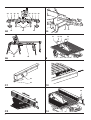
Adjusting the saw blade (fig. E1)
If the saw blade is wobbling during start up and run down, then adjust as
follows.
• Loosen the screw for the arbor collar (40) and rotate the blade (43) a
quarter turn.
• Retighten the screw and check to see if the blade has any wobble.
• Repeat these steps until the blade wobble has been eliminated.
Checking and adjusting the blade to the fence (fig. F1 - F4)
• Slacken the mitre latch (8).
• Place your thumb on the mitre lever (7) and squeeze the mitre latch (8)
to release the mitre arm (9) (fig. F1).
• Swing the mitre arm until the latch locates it at the 0° mitre position.
• Pull down the head and lock it in this position using the lock down
button (3) (fig. A1).
• Check that the two 0° markings (47) on the scale (10) are just visible
(fig. F2).
• Place a square (48) against the left side of the fence (11) and blade (43)
(fig. F3).
Do not touch the tips of the blade teeth with the square.
• If adjustment is required, proceed as follows:
• Loosen the screws (49) and move the scale/mitre arm assembly left or
right until the blade is at 90° to the fence as measured with the square
(fig. F4).
• Retighten the screws (49).
Checking and adjusting the blade to the table (fig. G1 - G4)
• Loosen the bevel clamp handle (12) (fig. G1).
• Press the saw head to the right to ensure it is fully vertical and tighten
the bevel clamp handle.
• Place a set square (48) on the table and up against the blade (43) (fig. G2).
• Remove the M10 hex nut (56) and fit the guard as shown (fig. I2).
• Replace the nut and tighten so that the guard is fixed in position.
• To remove the guard, proceed in reverse order.
Adjusting the riving knife (fig. A1, J1 & J2)
The correct position is for the top of the riving knife (31) to be no more
than 2 mm below the highest tooth of the blade and the body of the radius
to be a maximum of 5 mm from the tips of the saw blade teeth (fig. J1).
• Remove the saw bench table.
• Loosen the Allen screw (57) which allows both the bracket to rotate
and the riving knife to move up and down (fig. J2).
• Rotate the bracket and slide the knife either up or down until the
correct position is attained.
• Retighten the screw (57) firmly.
• Replace the table.
Lubrication
This machine requires no additional lubrication. The bearings of the motor
are pre-lubricated and watertight.
• Avoid using oil or grease as this can cause clogging with sawdust and
chips and create problems.
• Clean the parts subject to accumulation of sawdust and chips
periodically with a dry brush.
Instructions for use
Always observe the safety instructions and applicable
regulations.
The attention of UK users is drawn to the „woodworking machines
regulations 1974“ and any subsequent amendments.
• Ensure the material to be sawn is firmly secured in place.
• Apply only a gentle pressure to the tool and do not exert side
pressure on the saw blade.
• Avoid overloading.
• Always remove the dust from the machine after using to
ensure the lower guard operates properly.
Do not touch the tips of the blade teeth with the square.
• If adjustment is required, proceed as follows:
• Loosen the bevel clamp handle (12) (fig. G1) and turn the vertical
position adjustment stop screw (50) in or out (fig. G3) until the blade is
at 90° to the table as measured with the square (fig. G2).
• If the bevel pointer (51) does not indicate zero on the bevel scale (52),
loosen the screws (53) that secure the scale and move the scale as
necessary (fig. G4).
Checking and adjusting the bevel angle (fig. H1 & H2)
The bevel override knob (54) allows the max. bevel angle to be set at 45°
or 48° as required (fig. H1).
- Left = 45°
- Right = 48°
• Make sure the override knob (54) is located in the left position.
• Loosen the bevel clamp handle (12) and move the saw head to the left.
This is the 45° bevel position.
• If adjustment is required, proceed as follows:
• Turn the stopscrew (55) in or out as necessary until the pointer (51)
indicates 45° (fig. H2).
While performing this adjustment, it is advisable to take the
weight of the saw head by holding it. This will make it easier to
turn the adjustment screw.
Mounting and removing the guard (fig. I1 & I2)
When the unit is being used as a saw bench, the fixed lower guard (18)
should always be used (fig. I1).
Prior to operation:
• Install the appropriate saw blade. Do not use excessively worn blades.
The maximum rotation speed of the tool must not exceed that of the
saw blade.
• Do not attempt to cut excessively small pieces.
• Allow the blade to cut freely. Do not force.
• Allow the motor to reach full speed before cutting.
• Make sure all locking knobs and clamp handles are tight.
Switching on and off (fig. A1)
• To switch the machine on, press the on/off switch (1).
• To switch the machine off, press the on/off switch again.
Basic saw cuts
Sawing in mitre saw mode
It is dangerous to operate without guarding. Guards must be in position
when sawing.
Ensure that aluminum workpieces are clamped securely.
Vertical straight cross cut (fig. A1 & K)
• Slacken the mitre latch (8) and subsequently squeeze it.
• Engage the mitre latch (8) at the 0° position and fasten the mitre latch.
• Place the wood to be cut against the fence (11).
• Take hold of machine handle and press the head lock-up release lever
(2) to release the head.
B&D_19a
27