1
NOVEMBER 2000
16-40089-l 01
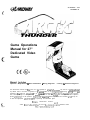
Game Operations
Manual for 27”
Dedicated Video
Game
Manual Includes
Operation &Adjustments * Parts Information ’ Wiring Diagrams
l
Testing & Problem Diagnosis
The manufacturer intends that this game is to be operated for amusement
purposes
only and not in contravention
0’
any federal. state or local law or regulation of !he Untted States or any foreign #country governing gaming devices. A:,
operators of this game are responsible
for its oxratIon I ! ? accordance WI:P such laws and regulations.
The manufacturer’s factory settings for this game may reoui:e adjustment in order to ccmpiy with laws applicable in an operator’s
specific jurisdlctlon.
It is the operator’s responsiQty to determlne
whether adjustments are necessary ald, if they are
to make the appropriate aujustments
prior to operating the amusement game.
M13wu4~
AMUSEMENT
GAMES.
3 4 0 1 NORT-! CALIFORV:& A V E N U E C+ICP.GO.
ht!~:Uwww.midway.com
LLC
ILLI~~O~S
60618 USA
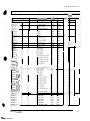
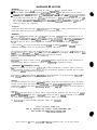
DECLARATIOr\J OF CONFORMITY
I
MIDWAY AMUSEMENT GAMES, I.,LC
3401 N. CALIFORNIA AVE.
CHICAGO, n, 60618
U.S.A.
WE, HEREBY DECLARE UNDER SOLE RESPONSIBILITY THAT
m MODEL:
"~ARCTlC~L~~DER"(27")40289,40389,4U489,4~89,40789,40989,41089.
41189,412i39,41389,4l489,41789,41889.
4.1989,42089.42I69,42289.42389,47189,47289,4B289
TO WHICH THIS DECLA!GTIOh
FOLLOWING EUROPEAN
(89/336/EEC
RELATES IS IN CONFORMITY WITH THE
PRODUCT SAFETY DIRECTIVES:
CTROMAGNETIC
COMPATIBILITY
DIRECTIVE
AND AMENDMENTS 91/C162/08, 92/31/EEC.93/68/EEC)
ELECTRICAL EOUIPMENT DESIGNED FOR USE J+‘ITIiIIN
CERTAIN VOLTAGE LIMITS DIREXX’iVE
(73/336/EEC AND AMENDMENTS
88/C168/02, 92/C210/01. 93/68/EEC, 94/C199/03, 95/C214/02)
AS IS VERIFIED BY COMPLIANCE WITH THE FOLLOWiN@
STANDARDS:
EN61000-4-2: 1995 EN61000-4-3: 1995
EN61000-4-4: 1995 EN61000-4-5: 1995 EN61000-4-6: 1995
Date issued:
Cktober 30,ZOOO
~.s#--cs
I
DAN GALARDE
CORPORATE V.P. OF QUALITY
---
4
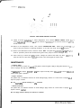
R&r to t.he manLfac;urer’ s ~iis?ruct~ons
over! actlv,ti
5
Fasren
the !?ub to ?ie bottom of the most central cabinet fusmg a hook-and-loop type material. Orlen:
the nub so that the indicaror lights are vlslble
and cable jacks are accessible
6
M&e sure excess cable !s tied in:@ a co11 and ihar all cables are routed through the notch II !he rear
ooor. Connect rhe AC. adap:ei for :he hub ald all line cords to AC power
,i,
-‘k7
7.
-
-
to s e! the hub switches for iNk’ (IInk)
ar,d X (cross-
CAUTION
0, no: conr~ect or disconnect any cable to the game electronics or hub wlth the powtr turned
1on Circuit dlsrtipnons may damage the game and void the warranty.
-rd
L
in c.rder
-
i
-
-
&itch 03 power aqd closely observe the screen for each cabinet during start up. Each automatically
enters ATTRACT MODE if nc errors are found Refer to Tro&leshooring
in the operation manual If
errors are detecxed.
8. Verify softtiare version compatibility for each game machine. Newer versions may contain %tructions
previous versions do not causing games to halt or reset at random.
Un!ock the coin door for each cabinet to access the operator contra! buttons inside coin vauit Press
and hold the TEST button :? enter the menu system. Select SYSTEIV INFORMATION MEN\lil at ?ne
Main Menu screen. Scroll to SOFTWARE VERSION and press the TEST button. Observe scrsan for
desired inform&o?
9.
Assign game machme
a link number. Select ADJUSTMENTS from the Main Menu xreen. Ssrsl’ or, an3
select GAME LINK NUMBER by pressing the Test button. Assign a linking number rangmg from 1 to 3
to each game cabcnet.
NOTE: Each c&net must have its own individual and unique number. The first cabinet on the leh
aiways
caD!net
7, the second is cabinet 2. etc.
IS
10. Repeat these steps for each .emaining game cabinet you wish to link
11. Close and lock the coin ooor, and reinstall and !ock the rear door for each cabinet Lower the leg levelers for each cabinet until the casters do not touch the floor and the cabinets are level. Lock the leveiers
in poslt,on
by tightening tne Puts provided.
OP E R A T I O N S
hex: T+NDEQ
C-APTEF
1 OFRATION
SAFETY
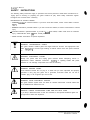
INSTRUCTIONS
The following safety instructions apply to operators and seduce
personnel. Read these instructrons before
servicing or prepar’ng the Vloeo Game Machine !‘VGM) fo- play. Other saiety instructions appea- throughout th1.s manual.
DEFINITIONS OF SAFETY TERMS
DANGER Indica:es an imminent hazard. If you fall to avoId This hazard, !t WILL cause death or serious
injury
. WARNING Indicates a poten% hazard. If you fall to avoid tf?s hazarc!. it COULD cause death or serious
injury.
l
CAUTION lndlcates a potential hazard If you fall to avold tl?is hazard. It MAY cause minor or moderate
injury. CAUTION also aierts “01 about unsafe practices
* NOTE indicates informatlsn cf special importance.
l
Y
_
7
:
_
_
___-
WARNING: TRANSPORTING GAMES.
: The VGM contaics glass and fragile electronic deuces. Use applropriate care wrier1
transponing, A;o d rough handling when moving the cabinet. Do not move with the
: power switcheo cn.
WARNING: DISC-ONNECT POWER.
Always turn tne power OFF and unplug the VGM before attempl.ing
service or aojustmerits unless othxwise Instructed. Installing or reparring boards with power switched 0’1
can damage components and votd the warranty
WARNING: GROUND GAMES.
Avoid electrical sxxksl Do not plug in a VGM until you have Inspected and properly
grounded It Only plug this game into a grounded, three-wrre outlet. Do not use a
“cheater” plug or cut off the groind pin on the line cord.
t
___~
~~
!
A
WARNING: AVOID ELECTRICAL SHOCKS.
The VGM system, does not utilize an isolation transformer. Internal cabinet AC is not isalated from the ex:emal AC line.
!
A
WARNING: HANDLE FLUORESCENT TUBE AND CRT WITH CARE.
If you drop a fluorescent tube or CRT and ii breaks, it will Implode! Shattered glass, can
fly eight fee! or more from the implosion.
I
4
1
/
I CAUTION: CHECK POWER SELECTOR, LAMP.
Set the 115:23%‘AC selector on the power supply for the COrreCt line ‘voltage.
Check the
seiector se%ng before switching on the VGM. Verify that the fluorescent lamp assembly
is correct for tne iocai line voltage.
t
CAUTION: USE PROPER FUSE.
Avoid elecincai shock! Replacement fuses must be identlcaffy
current ratings r-rust be identically rated to the origrnaf fuse.
2
rated. Fuse voltage and
/
j
~
I
1
.
CHARTER
1 OPERATION
CAUTION: AlTACH
CONNECTORS PROPERLY.
Be sure board connectors mate properly. if connectors do not slip cn easily. do not force
them. A reversed connector may damage the VGM and void the warranty. Connector
keys only allow a connector to frt one set of prns on 2 board
t
CAUTION: USE CARE WHEN SHIPFING HARD DISKS.
The hard drsk drive must be packed rr an anti-static bag. When shrpprng
the drive for
repair or replacement. pack it in an approved container r,PIN 08-8068). Do not stack or
drop hard disk drives.
WARNING: HAZARD TO EPILEPTICS.
A very small portion of the population Tas a condition whrch may cause them to experrence epileptrc seizures or have momentary loss of consciousness when viewing certain
kinds of flashing lights or patterns that are present in our daily envrronment. These persons may experrence serzures while watching some kinds of ?elevisron
prctures or playing certarn video games. People who have not had any previous seizures may
nonetheless have an undetected epileptic condition.
If you or anyone in your family has experienced symp!oms
linked to an epileptic condition (e.g., seizures or loss of awareness). rmmedrately
corsult your physician before
using any video games.
We recommend that parents observe :heir children while they pllay video games. If you
or your child experience the following symptoms: dizziness. altered lvrsron, eye or muscle
tvvrtching.
involuntary movements. loss of awareness disorientabon, or conwlsions,
DISCONTINUE USE IMMEDIATELY and consult your physlcrar
Ax-IC
THUNDER
‘i
C+wTER
1 OPEPrZTICFd
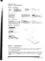
PRODUCT
Operating
SPECIFICATIONS
Requirements
iocar,or
~lectncai
Domestic
Foreign
Japan
12OVAC. Q 60Hz 4.‘? Amps
230VAC & 50Hz 2.1 Amps
1110VAc Q 50Hz 4 I Amps
Cabinet
Shymna
32’F te 100-F
;occ to :38x)
statistics
Dmem@
lVidih 30” (715 2 cm)
Depth 62” (157.d cm 1
Height 78” f19a cm
Game
i-%7 er3m
Power
S,hioDrnq
350Lbs
125Lbs
we’&
tappox )
[158kgl Main Cabinet
j57kgi Seal Assy
&siqn Tvoi
Sit-On Dedlca:ed
Video Gan:?
MachIne Mlth Steering Feej5 1:~.
Characteristics
P/aver Variabie>
ooeraior
i to 4 players pe: VGM iwith i!nk.n: t
HI@ Score Recognit!on
SuItable for All Aces (AAM. CertifleJ!
Coirage. Play Mooe. D tiicultjr.
Volume Aud:ts, Statistics
Equipment
\‘anabies
Characteristics
audio svstem
DigIta! Stereo
5” (12.7 cm) Coaxial Full Range
Speakers
9mxcv Accsmx
2 Coin Mechac%ms
Dollar Bill Vailaa!or
Read)
Eiectron~c Corn Acceptor Readr
PRODUCT
l
l
3
CONFIGURATION
Stand Alone Video Game Machine
Each VGM is ready to play right out of the box. Operators, may use the menu screens in the garw menu
system to dete:mine some pIaye r variables in advance or ieave the choices up to the players
Linked Video Game Machines
Linkmg
allows players to compete against each other on a shgle course. Operator menus are used tne
same way as in stand-alone gane machines. Crossover couplers and linking cables to connect t%,3
VGMs are factory installed. Use an optional 10 base-T ethernet hub to interconnect up to four VGlds
M
IDWAY
AMLSEMENT
GAI%‘E:
i1.C
I
CI+A”TER
1 OPEW-ION
SET-UP
1. Remove all Items from shrpprng contarners and set them aside. Remove all
Inspect exterior of the marn cabinet and sea? pedestal for any damage.
packagrng material.
WARNING
Cabinet IS top heavy. Do not push agarnst plastic parts durrng movement
2.
Remove keys from controller assembly. Unlock and open rear door. coin box and cash box. Electrical
cords, mechanrcal components, and assorted spare parts are packed inside cash box. Casters and leg
ieveiers for the cabinet and pedestai are packed inside of a box with the seat pedesiai.
3.
Locate casters, leg levelers and related mounting hardware
3.
Install one nut onto each leg leveler Tilt main cabinet as needed to locate threaded holes rn undersrde
of cabinet. Install a leveler and nut into each hole. Do not trgnten nuts at this time. Repeat these steps
for seat pedestal as wel!.
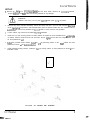
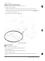
5.
InstaIl the provided swivel casters. Insta!i the six (6) swiveling casters on the main cabinet and seat
pedestai as shown rn the illus?ratron
be!ow
6
Install provided locking casters. Install the twc (2) locking casters on seat pedestal as shown iri the
illustration below.
LOCATION
ARCTIC
m-W.---
TWNDER
OF
CASTERS
AND
LEVELERS
5
C,i?pTEF!
1
OPERATlOh:
7.
Roil cabinet to its intended iocation maintainrng clearance between the cabrnet and walls, drapes
other games or obstructrons.
8.
Locate the pedestal assembly mo~trng
wrth the hardware. inside a cash box.
9
Install rubber bumpers Rubber bumpers are used too maintain a X16” space between the pedestal ar’cl
cabinet assembly. and are essentral rn absorbing vibratron
insert one bumper using a twisting motion
into each of the pre-drilled holes !oca:ed
along the bottom edge oi main cabrnet assembly
rails and rilbber bumoer spacers. which are shopped
along
10 Install pedestal mounting rails Orlen: !he mounting rail so that the pre-attached rubber bumpers face
outward, then insert rai!. Fasten raei w piace with the hardware provrded. If necessary refer to illustratron for proper placement.
11 Roll pedestal section near main caotnet,
alrgn opening rn the pedestal with the ends of the ra s
mounted rn main cabinet. Skae tre pedestal forward onto extended mount,ng rails leaving enougn
space to attach the ,winng harness F,la!e each cable connector and press firmly to seat the contacts
Ensure no wires are pinched during pedestal attachment
Attach pedestal assembly using -“L-20 tamoer resistant screws and large flat washers provided. AT27
wrench is included to tighten these screws firmly.
LOCATION
OF
PEDESTAL
ASSEMBLY
MOUNTING
HOLES
1 2 Lower and adjust each leg leveler urtrl the pedestal section IS stable and level. Adjust the levelers until
the bottoms of al! pieces are fiush snd parallel with each other. Inspect for bindlng or p:nched wires.
then firmly tighten the fasteners to a’tach the two pieces together as a single unit.
13. An extra padlock may be insta!led to secure rear door Locate hasp. Remove the two lock bracket nuts
from inside the cabinet, above the rear door opening. Slide the hasp bracket onto the bolts so tha: It
protrudes from the hole rn back of the cabinet. then rernstall
nu!s
6
MIDWAY AMUSEMENT GAMES.
LLC
C-A~TE~ 1 OPE~l4TION
P
TYPICAL REAR DOOR HASP INSTALLATfON
14. Modify the lock plate at the top of ihe rear door. Remove the bolts and nuts from ttle lock plate. then
rotate !he plate so that the slot WII be above the door. Reinstall the bolts and nuts arrd tighten firmly.
15.
Reinstall the rear door onto the cabinet and close it. Lock the rear door and remove the key. If
required, rnstall the extra padlock through the hasp at this time. install the screws at the top and srdes
of the rear door and tighten snugly. Leave the remainrng doors open at this time.
LINE COf?D I N S T A L L A T I O N
16. The power cord is packed in with the spare parts. insert a portron cf the lrne cord in the cord clamp
leavrng
enough slack for the cord. Match the holes on the IEC plug ,tirth the prongs in the receptacle
and push firmly to seat the line cord.
17. Plug the game into a grounded (3-terminail X wall outlet. Switch on power to the game using the ON/
OFFswrtch located on the upper ieft top of -he cabinet (when viewed from the player’s positron). The
game will power up and begin its self test. Ii no errors are found. the game will automatically enter the
attract mode of operatron (scenes and sounc!s from typicai
races. player’s scores, messages, etc.).
18 Open the corn door. Press and hold the Begjo Test button on the operator control switch panel to enter
the menu system. Wait untrl the Main Menu screen appears on the monrtor.
ASCTIC TH~NDEP
7
CHAPTER 1
OPERATION.
.I
XI
‘9
*,
, /,’
0
TYPICAL COIN DOOR SWITCH LOCATION
19 Follow on-screen ?nstructions to select Diagnostics. then choose SWITCH TESTS. Follow t-i P
screen lnstructlons to verity that ea,h of the controls is operaTIonal. If no errors are found, the ccni-z’s
should function well.
20 Return to the Diagnostics screen, then choose CONTROLLER TEST. Follow the on-screen i?c”.~:tions to veriiy the presence of steering resistance. If no errors are iound, the aim will be good.
21. Return to the Main Menu screen, and then choose EXIT. The game will automaticaily ecter its ‘a7 .::
mode of operation (scenes and sounds from typical races, player’s scores. messages. etc.).
22. Insert currency or tokens and pla) a game. Change the volume and make any other adjustxc’
Close and lock al! open doors. Tighlen the leveler nuts and engage the caster locks
!i
MAINTENANCE
Viewing Glass
It is not necessary to switch off poiver tc the game to clean the glass. Apply a mild glass cleaner to a : Z-Y
cloth or sponge and wrpe the viewing glass.
l
Do nor apply the cleaner direct/y on the g/ass! Liquid could drip down Into switch or control clrcuxs :: :
cause erratic game operation.
Player Controls
Use plastic-safe, non-abrasive cleaners to avoid damage Apply cleaner to a clean cloth or sponge ar ;
wipe the player controls.
l
Do not apply
the cleaner directly on rbe controls!
Cabinet and Seat
Use plastic-safe, non-abrasive cleaners to avoid damage. Apply cleaner to a clean cloth or sponge ar .:
wipe the seat or cabinet.
l
Do not apply cleaner directly on artwork or cabinet’
C HAPTER 1 OPERATIO~J
CONTROL BlJlTONS
TEST BUTTON activates game Meru System. Press the Test button 10 access the Maln Menu and
select individual diagnostjcs, audits utllitles.
etc.
l
VOLUME-UP BUTTON is used to m3ve
Increase volume level in game play.
l
VOL WE-DOWN BUTTON IS used to mo\‘e down tqrough menu selections or adjustment items. as AE?!~
as to decrease volume
lcvci in ga-ae pla).
l
l
up through menu selectlons or adlustment items as well as I:)
SEEVEE CREDITBU7CN
is JSX to allot credits without affecting a game’s bookkeeping total. This
button is also used to exit a menu s4ection or rett.rn to the rnaln menu
10
Micw~v
AMUSEMENT GAMES. LLC
A D J U S T M E N T , DI A G N O S T I C &
AUDIT
AXTNC
MENUS
T HUNDER
-
C-APTFF
))Menu,
2 DlAGYOSTiCS
contin-ued
IjS1IS’em
-~
lnfoynation Menu
_ _ _
I/
..--- /
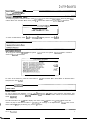
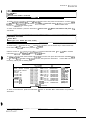
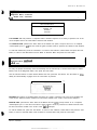
SYSTEM INFORMATION MENU
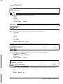
To verify the game’s software version. reset in’crmation. or to clear reset Inlormatlon. select System Intormatron Menu from the Main Menu. then press !he Test button Select and petiorm destred function.
SYSTEW IhFXMATlON
MEt<L
SOFTi’dL,RE
VERSION
BACK TO PREVIOUS MENU
To return to Main Menu, select Back to Pre’vious
FSenu
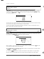
To verify game software version, select System ‘.!ers:on
screen for desired Information.
and press the Test buttcn
from the System InformatIon
Menu. Observe
1 .o.o.o
1 .o.o.o
1 .o.o.o
1 .o.o.o
1 .o.o.o
l.Q.Q.Q
1.0.0.0
To return to the submenu, press the Test button to retilrn to the Main Menu select Back To Previous Menu
and press the Test bugon
jj Main Menu, &hued
/’ Audits Menu
I=====
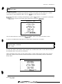
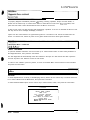
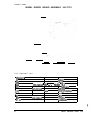
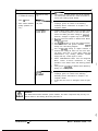
AUDITS MENU
To view a game’s play statistics, select Addits 4fler,u from the Main Menu. tnen press the Test button. Use
the Volume buttons to scroll to desired audit item, t?en press the Tes! button. Follow on-screen instructions
where necessary
The left-hand side of an audit table displays the name of the audlt Item: the rqht-hand side shows the
amount of play for that item as either a percentage an average. or as elapsed time. Piease note, record
these statistics prior to performing any service cr repairs.
A RCTIC THLJWIE?
3
rhlain Menu,
continued
A,JIDIT’
F.“Ehi:
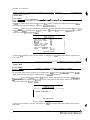
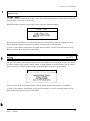
G E N E R A L G A M E A U D -Z
WAS!+NGTON.
D.C
SWISS ALPS
CHERNOBYL
HIMALAYAN
ALASKAN
PIPELINE
HAUNTED
FOREST
COIN AUDITS
CREDIT AUDITS
SYSTEM AUDITS
WATCHDOG
AUDITS
CLEAR ALL
BACK TO PREVIOUS MENU
To rettim to submenu Ivh!le >,iewlng
a~. audit table, press the Test outron; to return to the Main Menu select
Back To Previous Meru and press the Test button.
rue”
i~General Game Audits
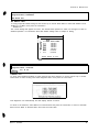
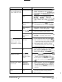
LGENERAL GAME AUDITS
To view game audits. press the Vo!um~, iip or Volum-= Down button to select General Game Audits from
the Audits Menu, then press tne Test DJttoc Observe screen for desired information.
GENERAL
TOTAL UPTIME
TOTAL PLAYTIME
PERCENTAGE
PLAYTIME
GAMES STARTED
AVERAGE GAME TIME
PERCENTAGE FREE GAMES
TOTALTIME-OUT PERCENTAGE
GAME
CONTINUES
PERCENTAGE
INITIALS ENTERED
1 PLAYER GAME
2 PLAYER GAME
3 PLAYER GAME
4 PLAYER GAME
5 FLAYER GAME
6 PLAYER GAME
7 PLAYER GAME
6 PLAYER GAME
PERCENTAGE ATTACK USED
PERCENTAGE NO DRONES
PERCENTAGE NO CATCH-Up
D!RTY M C K U R D Y S E L E C T E D
MAI ZHOU LIN SELECTED
AGENT 5 SELECTED
GAME
ZDAYS 09:09:11
ZDAYS 02:X3:10
(9,‘32) 25%
%AYS Ol:l2:15
AUDITS
WILLIE QUINN SELECTED
PONZO SELECTED
CANDY ICE SELECTED
SLED 1 SELECTED
SLED 2 SELECTED
SLED 3 SELECTED
SLED 4 SELECTED
SLED 5 SELECTED
SLED 6 SELECTED
WASHINGTON,
DC
SELECTED
SWISS
ALPS SELECTED
CHERNOBYL SELECTED
HIMALAYAN
SELECTED
ALASKAN
PIPELINE
SELECTED
HAUNTED FOREST SELECTED
PLAYER WIPE-OUTS AVERAGE
PUP BOOST AVERAGE
PUP MlSStLE
AVERAGE
P U P SHiELD
AVERAGE
PUP SUPER ATTACK AVERAGE
PUP HEALTH AVERAGE
PUP TRICK AVERAGE
/
RETURN
CLEAR
./(
I(
a‘
!
C H A P T E R 2 DIAGNCISTICS
j
~?a” Menu. continued
I! Audk
Menu
(1 General Game Audits. continued
..~
I’
To reset auS tah:e seieci Clear located at :he acrtom of screen. then press the Tes! button. To leave !ab/e
as it is. select Re!;rn
locaied at the bottom 31 screen.
ther. press the Test button P/ease
,zote. be sure to
record any va!ucs znor to clearing table
To return to the submenu. press the Test button: .o return to the Maii-i Menu select Return and press tCle
Test button
~/ Audits Menu
I Washington, D.C. Audits (All track audits)
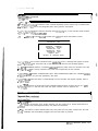
WASHINGTON, D.C. AUDITS
To observe the aLd,ts screen for any lone of the !eatursd tracks, use the Volume Up or Volume Down button to select the sewed audit. then press the Te5.t button.
Observe screen fcr desired informa:ion. f’leese rmote. each sled track listed in the Audit Menu contains
information iden:;cai
to informatIon
shown in tne iabie below.
#
To reset ax!: I& e select Clear located at :he bcttom of screen. then press the Test button. To leave rabie
as it is. select Reium located at the bN>ttom of screen, then press the Test button
f/ease note. be sure to
record any values prior to clearing table.
ARCTIC TALk:ER.
WASHINGTON DC
TIMED
TIMED
TIMED
TIMED
TIMED
TIMED
TIMED
TIMED
TIMED
TIMED
TIMED
TiMED
TRACK SELECTED
TRACK SINGLE PLAYER
FREE GAME AWARD
TIME-OUT
PLACED 1 ST
PLACED 2ND
PLACED 3RD
PLACED
4TH
PLACED 5TH
P L A C E D 6TH
P L A C E D 7TH
P L A C E D 8TH
RETl!RN
-____
AT 90
PERCENTAGE
AT 95
PERCENTAGE
AT 100
PERCENTAGE
AT 105
PERCENTAGE
AT 110
PERCENTAGE
AT 115
PERCENTAGE
AT 120
PERCENTAGE
AT 125
PERCENTAGE
AT 130
PERCENTAGE
AT 135
PERCENTAGE
AT 1 4 0 P E R C E N T A G E
AT 145
PERCENTAGE
pm)
(x/X)
(x/x)
(xx)
(wx)
(XIX)
(x/X)
0.036
0.0%
0.096
0.0%
0.0%
0.0%
0.0%
;gj
(XIX)
(XIX)
(X*X)
;:;;
0.0%
0.0%
0.0%
CLEAR
To return to the submenu. press the Test button io return to the Main Menu select Return and press the
Test button
C HAPTE R 2 D
/I
AGNOSTICS
Audits Menu
(, Coin Audits
~~
-~~ ~~
L~a_ _ ~___
_ _ _
-____
COIN AUDITS
To vrew corn audits use the Volume Up o. Volume DOW button to select Coin Audits from the Audits Menu
then press the Test button Observe screen for desired informatIon.
70 reset audrf fable. select Clear located at the bottom 0: screen. then press the lest button 70 leave fade
as !f k. select Hetum located a! the b&om of screen, ther press th& Test button Piease ncfcn, be sure to
record any values prior to clearing table
LEFT SLOT COINS
RIGHT SLOT COINS
B!LLS
CENTER SLOT COINS
EXTRA SLOT COINS
SERVICE CREDIT
TOTAL PAID CREOIT
TOTAL
;
::
X
X
:X.Xx
RETURN CLEAR
To return to the submenu. press the Test button, to return to the Main Menu select Return and press the
Test button
/ Main Menu, continued
/ Audits Menu
i/ Credit Audits
,CREDIT AUDITS
To view credit audits use the Volume Up or Volume Down buttor to select Credrt
Menu. then press the Test button Observe screen for dewed information.
Audtts from the Audi?s
T o resefaodif fable. select C.lear located at the bottom of screen. then press the Test button. TO leave faDk
as if is. select Return located at the botom of screen, then press the Test button. Please note, be sure to
record any values prior to clearrng !able.
CRED’T
AUDiTS
k----
/
CREDIT AVAILABLE X
j
RETURN CLEAR
‘--
j
To return to the submenu, press the Test button: to re!urn to the hlain Menu select Return and press the
Test button
f
-
6
MIDWAY
AMUSEMEK GAMES
LLC
CHAPTEH
2 DIAGNOSTICS
Main Menu, continued
/! Audits Menu
/I System Audits
SYSTEM AUDITS
To view system audits, use the Volume Up or Volune Down button to select System Audits from the Aucrts
Menu, then press the Test button Observe screer !or desired rnfxmallon
To reset audit table, select Clear focated at the bottom of screen, tnen press the Test button. NOTE: Be
sure to record any values prror to clearing taole ZI leave rab!e as ,f is select Reiurn located at the bottom
_,~
_,~ ---_,- -~~
oi screen, men press me resr ouiiorr
SYS’37 AUDITS
GAME STARTUPS
GAME
RESTARTS
CSM STARTUPS
GAME NE’S
/ E%Fss
GAME UPTIME
SYSTEM UPTIME
I
c
I
I
::
c
X DAYS 0O:OO:OO
X DAYS 0O:OO:OO
!
RETURN CLEAR
To return to the submenu, select Return and press the Test button: to return to the hlarn Menu scroll to
Return and press the Test button.
I
I/
Audits Menu
I/ Watchdog Audits
WATCHDOG AUDITS
To either view or clear information about the vv a ??dog use the Voiume Up or ‘Volume Down button to
select Watchdog Audrts from the Audits Menu then press the TEsi button. Observe screen for desired
information.
To reset audd iable. select Clear focated at the coltom of screen. then press the Test button. NOTE: Be
sure to record any values prior to clearing table. Tc! leave tab/e as :t is. select Return located at the bottom
of screen, then press the Test button.
‘JJATCHDOG
ALDITS
VIE’S; MrATCHDOGS
C L E A R \YATCHDOGS
BACK TO PREVIOUS MENU
To return to the submenu. select Return and press the Test button: to rerun to the Marn Menu scroll to
Return and press the Test button
ARCTIC THLNDEH
7
CHAPTER
2
DIAGNOSTICS
Main Menu, continued
I
Audits Menu
I
) Clear All Audits
CLEAR ALL AUDITS
To clear all game audits use the Volume Up or Volume Down button to select Clear All Audits from the
Audrts Menu, then press the Test button
Use the Volume buttons to select desired answer, then press the lest button. Observe a confirmation box
appears on-screen to verify a selection was made.
I
I
CLEAR ALL AUDITS
1
CLEAR
ALL
YNEOS
ARCTIC
THUNDER
1
AUDITS
To return to the submenu, select Return and press the Test button; to return to the Main Menu scroll to
Back To Previous Menu and press the Test button.
Main Menu, continued
1 Adjustments Menu
ADJUSTMENTS MENU
To optimize game periormance and earnings or to change the look or sound of the game, use the Volume
Up or Volume Down button to select Adjustment Menu from the Main Menu, then press the Test button.
The Adjustments Menu enables customization of Attract Mode, fan and seat shaker intensity, game diffrculty, as well as a whole host of other features. Please note, individual Game Adjustments are explained in
more detail on the following pages.
To select a menu option in Adjustments use the Volume buttons to select it, then press the Test button
I
ADJUSTMENT
MENU
I
GAME LINK NUMBER
MINIMUM GAMEVOLUME
GAME DIFFICULTY
SINGLE 1ST FREE GAME
LINK IST FREE GAME
GAME START TIME
fNITlALS
ENTRY
FAN INTENSITY
SHAKER INTENSITY
TAIL LIGHT
WHEEL STRENGTH
FAMILY MODE
RESTORE FACTORY ADJUSTMENTS
BACK TO PREVIOUS MENU
8
MIDWAY AMUSEMENT GAMES, LLC
/,
CYAPTE?
2 DIAGNOSTICS
Main Menu, continued
i.”
Adjustments Menu, continued
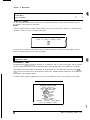
Many line items in the Adjustments Menu provide multiple setting chol,:es,
a few of which are followed by a
confirmation box as shown below to verify your selection prior to completing the request.
Be sure to read each option carefully, use the Volume buttons to select YES or NO, then press the Test
button to lock in the setting. Selecting NO cancels any changed values and returns the previous values to
memory.
1 ARE YOU SURE YOU WANT TO SELECT THIS SETTING? ~
YES
NO
TYPICAL CONFIRMATION BOX
; Main Menu, continued
Adjustments Menu
-~-.
Game Link Number
GAME LINK NUMBER
Allows the game link number to be set. The setting range is:
-Maximum:
4
1
-Minimum:
-Factory Setting: 1
Main Menu, continued
I
Adjustments Menu
.,.m ‘.A_
/ Minimum Game Volume
A
MINIMUM GAME VOLUME
Selects the minimum allowable setting for volume. The setting range for this adjustment is:
-Minimum:
-Maximum:
-Factory Setting:
ARCTIC THLNXR
0
255
20
9
C HAPTER 2 D IAGNOSTICS
GAME DIFFICULTY
Determines level of difficulty during game play. The setting
range
is:
-Easiest
-Easy
-Normal
-Hard
-Hardest
-No Change
-Factory Setting:
Normal
i Main Menu
~ Adjustments Menu
Single First Free Game
SINGLE FIRST FREE GAME
Enables the single play “free game for first place” option. The setting choices are:
-Enable (Award free game)
-Disable
-No Change
-Factory Setting: Enable
Adjustments
Menu
Linked First Free Game
LINKED FIRST GAME FREE
Awards free game to top player in a 2. 3, 4 or more player race. The setting choices are:
-Off (Does not award a free game in linked games)
-Must Beat All Drones (In a game with one or more linked players, a free game is only awarded if
each of the drones and linked plavers
lose)
-Two Players (In a game with at least two linked players, a free game is only awarded if the other
linked player loses)
-Three Players (In a game with at least three linked players, a free game is only awarded if the
other ltnked players lose)
-Four Players (In a game with at least four linked players, a free game is only awarded if the other
lrnked players lose)
-No Change
-Factory Setting: Off
10
MIDWAY AMUSEMENT GAMES, LLC
C HAPTER 2 D IAGNOSTICS
0
1
GAME START TIME
Adjusts the game start time. The setting choices are:
45
-Minimum:
-Maxtmum:
-Factory Setting:
90
55
INITIALS ENTRY
Enables players to enter their initials upon earning a high score, and displays high scores during attract
mode. The setting range is:
-Enable
-Disable
-No Change
-Factory Setting:
Disable
FAN INTENSITY
Determines fan speed during game play. The setting range is:
-Easy
-Medium
-Hard
-Off
-No Change
-Factory Setting:
Medium
Main Menu
Adjusfments Menu
_i.
_ii
Shaker Intensity
ii
SHAKER INTENSITY
Determines shaker rate during game play. The setting range is:
-Easy
-Medium
Q
-Hard
-Off
-No Change
-Factory Setting:
AXTIC THLNDER
Medium
11
CLADTER
2 DIAGNOWCS
pein Menu
i’ Adjustments Menu
j Tail Light
TAIL LIGHT.
Enables tar1 light illumination. The setting choices are:
-Enable
-Disable
-No Change
-Factory Setting:
Enable
I
/ ~~s~~k Menu
,
,i-Wheel Strength
WHEEL STRENGTH
Selects degree of wheel strength to be used for racing. The setting range is:
-Very Light
-Light
-Normal
-Heavy
-Very Heavy
-No change
-Factory Setting: Very Heavy
FAMILY MODE
Changes appearance of female character seen on logo screen. The setting range is:
-Drsable (Lewd appearance)
-Enable (Conservative appearance)
-No change
-Factory Setting:
Disable
,. “.
Main Menu
i Adjustments, continued
- _-.i
~1Restore Factory Adjustments
L.
RESTORE FACTORY ADJUSTMENTS
Allows operator to restore all game settings to the original factory default settings. The setting range is:
-Yes
-No
-Factory
12
Setting:
No
MIDWAY AMUSEMENT GAMES, LLC
C HAPTER 2 DIAGNOSTICS
-Main Menu, continued
.(I__
Diagnostics Menu
DIAGNOSTIC MENU
To verify condition of the electrical and electronic hardware in the game use the Volume Up or Volume
Down button to select Diagnostics Menu from the Maln Menu, then press the Test button.
Diagnostic tests assist in checking and adjusting the game’s major systems. It is important to periodically
run diagnostics to improve and maintain game performance and player satrsfactron.
I
DIAGNOSTICS
MENU
MONITOR TEST
SWITCH TESTS
DIP SWITCH TESTS
LINKING TEST
CONTAOLLER
TEST
SEAT SHAKER TEST
BLOWER TEST
LAMP TESTS
SPEAKER T E S T
BURN-IN TEST
VERIFY SOWARE
BACK TO PREVIOUS MENU
Use the Volume buttons to select desired Diagnostic Menu option, then press Test button to enter
To return to the Main Menu select Back To Previous Menu and press the Test button
Main Menu
Diagnostic Menu, continued
Monitor
Setup
MONITOR SET-UP
To verify color clarity of the monitor use the Volume Up or Volume Down button to select Monitor Setup at
the Diagnostic Menu, then press the Test button.
Within the Monitor Set-up menu use the Volume buttons to select desired monitor setting, then press the
Test button. Observe screen disolavs desired information and then automatically returns to the Monitor
Set-Up Menu
MONITOR
SET-UP
RED SCREEN
GREEN SCREEN
BLUE SCREEN
WHITE SCREEN
50% GRAY SCREEN
25% GRAY SCREEN
BLACK SCREEN
COLOR BARS
CROSS HATCH
BACK TO PR!IVIOUS
MENU
ARCTIC ThbNDER
13
--
__l-_l___.-__---
C HAPTER 2 DIAGNOSTICS
1 Ili
I
Main Menu
Diagnostic Menu, continued
1
’ Monitor Setup, continued
-
COLOR BARS. Observe 4 color bars in different shades appear on-screen as aids in adlustIng the green.
blue, and red color levels. Each color should appear sharp and clear. Check video brightness and contrast
The CROSSHATCH PATTERNS test fills the screen with a series of dots within a grid. Observe the dots
are perfectly round and that both the grid and dots are clear. inspect monitor convergence, linearity, and
screen we.
The single color screens, RED SCREEN, BLUE SCREEN, GREEN SCREEN, etc., fill the screen with a
single color to be observed for complete saturation and clarity.
If any of the tests show a need for CRT adjustment, use the proper knobs on the Monitor Controls board
To return to the submenu, select Return and press the Test button; to return to the Main Menu scroll to
Back To Previous Menu and press the Test button.
Diagnostic Menu, continued
Switch Tests
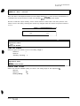
SWITCH TESTS
To verify proper operation of game switch and button inputs use the Volume Up or Volume Down button to
select Switch Test at the Diagnostic Menu, then press the Test button.
I
S W I T C H TTESTS
SWITCH
ESTS
WHEEL: XXX
GAS:
xxx
START
ATTACK
CREDIT VOL- VOL+
VOL+ TEST
TEST LCOIN
LCOIN
RCOtN
C
CCOIN
COIN
ECOIN BILL
PRESS VOLUME - AND + TO EXIT
Press any switch on the control panel or coin door to cause the corresponding indicator on the screen to
illuminate. Each illuminated square represents one completed switch circuit.
Press both Volume buttons simultaneously to return to the submenu: to return to the Main Menu scroil to
Back To Previous Menu and press the Test button.
14
MIDWAY AMUSEMENT GAMES, LLC
C H A P T E R 2 DI A G N O S T I C S
Main Menu
Diagnostic Menu,
continued
DIP Switch Test
DIP SWITCH TEST
To verify proper DIP switch setting use the Volume Up or Volume Down button to select DIP Switch Test at
the Diagnostic Menu, then press the Test button.
The current settings will appear on-screen. The default switch position for switch one through 8 is OFF for
standard operation. For information about DIP Switch settings refer to Chapter 5: Wiring.
I
DIP SWITCH TEST
I1
z
OFF
OFF
OFF
iz
;g
6
7
8
OFF
OFF
s2
BOOT GAME
UNUSED
UNUSED
UNUSED
UNUSED
UNUSED
UNUSED
UNUSED
PRESS ENTER TO EXIT
52 DIP SWITCH SCREEN
Main
Menu
Diagnostic Menu, continued
Linking
Test
i
“.
LINKING TEST
To verify communications between a game machine and others linked to it use the Volume Up or Volume
Down button to select Linking Test at the Diagnostic Menu. then press the Test button.
This diagnostic runs automatically and will display results on-screen
To return to the submenu, select Return to Previous Menu and press the Test button; to return to the Main
Menu scroll to Back To Previous Menu and cress the Test button.
AR C T I C
T HUNDER
15
-.
-iqnck
hnu, continued
‘I
‘!
e Test
.i
-- ---- k-2.,-El3
TEST
_k
: --- .-e crcc~’ c.rectronal
movement of the controller assembly use the Volume Up or Volume Down
_- ---~. :: 5+ 5:: C:-::oller Test a? the Diagnostic Menu, then press the Test button.
:.xz
z +:s: -::I a’~,:“: -ontact with controller assembly when conductrng any of the controller tests because
-5 ::-r:, +- 2’22’ritlcal~y turns on its own.
.:=
.
I -I/ if ci .ons to select desrred controller test optron, then press Test button to enter
CONTROLLER
TEST
I
CALIBRATE
FEEDBACK
CONTROLLER
CENTER
CONTROLLER
LEFT
CONTROLLER
RIGHT
CONTROLLER
INFO
BURN-IN TEST
RETURN TO PREVIOUS MENU
I%+-.+ Z-C fotloti the on-screen instructions when conductrng a test. A message will appear on-screen
-_Li.
-_ _.-= : compreted
test. Press the Test or Start button to exit test once this message appears.
>-5.=-i 7 FEEDBACK performs a complete calrbration sequence which turns the controller to the left,
_.- r --:- L- 1 :o ‘he right at a variety of speeds. This is the most complete test for the controller.
--< ZC’bTCLLER CENTER, CONTROLLER LEFT, AND CONTROLLER RIGHT are individual controlr------::2 ~~‘1 41 perform only the test specified by the name.
--+ Z3TCLLER
5-5 :J test.
.--T
_
INFO test does not automatically turn the controller and requires operator input to
:,=?i-\r
Z-ST performs the same tests as the Calibrate Feedback option, except it does so in a com--e
-- -e,mJpted
cycle. To exit this test mode the game machine must be powered off.
==‘- s-JKER TEST
_A.__I -; oroper functionality of the shaker assembly use the Volume Up or Volume Down button to
~51 2~ Shaker Test at the Diagnostic Menu, then press the Test button.
FZ_ _ _;. .: -me buttons to select desired shaker test, then press the Test button. Please note, the seat
i-2.5. L’ -mediately and automatically engaged once the Test button is pressed.
MIDWAY
AMUSEMENT GAMES, LLC
C H A P T E R 2 DI A G N O S T I C S
Diagnostic Menu, continued
Se&
Shaker Test, continued
-
-
SEATSHAKERTEST
SHAKER ON
BURN-IN
RETURN
The SHAKER ON test performs a complete shaker vibration sequence at a variety of speeds. This is the
most complete test for the seat shaker. Observe seat vibration.
The BURN-IN TEST performs the same tests as the Shaker On option, except it does so in a complete,
uninterrupted cycle. To exrt this test mode the game machine must be powered off. Observe seat vibration.
To end seat shaker test, press the Test button. To return to the submenu, select Return and press the Test
button; to return to the Main Menu scroll to Back To Previous Menu and press the Test button.
Main Menu
Diagnostic Menu, co+wed
_ ,,
Blower Test
BLOWER TEST
To verify the proper functionality of the fan assembly use the Volume Up or Volume Down button to select
Blower Test at the Diagnostic Menu, then press the Test button.
Use the Volume buttons to select desired blower test. then press the Test button. The fan blower is immediately and automatically engaged once the Test button is pressed.
BLOWER
TEST
BLOWER ON performs a complete blower sequence at a variety of speeds. This is the most complete test
of the blower. Observe breeze emitted from fan blower located in the center of the back-lit marquee.
BURN-IN TEST performs the same tests as the Blower On test optcon. except it does so in a complete,
uninterrupted cycle. To exit this test mode the game machine must be powered off. Observe breeze emitted from fan blower located in the center of the back4 marquee.
To end fan blower test, press the Test button. To return to the submenu, select Return and press the Test
button; to return to the Main Menu scroll to Back To Previous Menu and press the Test button.
AR C T I C
T HUNDER
17
C HAPTER 2 DIAGNOSTICS
1 Main Menu
I’
Diagnostic Menu, continued
I
Lamp Test
--/
LAMP TEST
To detect intermittent or faulty incandescent bulbs use the Volume Up or Volume Down buxon to select
LAMP TEST at the Diagnostic Menu. This test ensures that the incandescent bulbs critrcal to game operation function properly.
LAMP TEST -/
Use the Volume Up or Volume Down button to select desired Lamp Test and press the Test button. During
the test observe the Lamp(s) turn ON according to the option selected.
To return to the submenu, select Return and press the Test button; to return to the Main Menu scroll to
Back To Previous Menu and press the Test button.
~Main Menu
! Diagnostic Menu, continued
!I12pzaker Test
SPEAKER TEST
To verify the proper functionahty of the speaker assemblies use the Volume Up or Volume Down button to
select Speaker Test at the Dlagnostx Menu, then press the Test button.
I
SPEAKER
TEST
I
RIGHT CHANNEL
LEFT CHANNEL
I KHZ SOUND
1 OOHZ SOUND
PLAY TUNE
RETURN
RIGHT CHANNEL. Tests the functionality of the speaker located on the right-hand side of ihe game cabinet by emitting an audible voicing of the word “right.”
LEFT CHANNEL. Tests the functionality of the speaker located on the left-hand side of the game cabinet
by emitting an audible voictng
of the word “left.”
The 1 KHz and 1OOHz
Sound tests are audible tones emitted from both speakers on the game cabinet
Play Tune test option emits audible music from the game using both speakers on the game cabinet.
18
MIDWAY AMUSEMENT GAMES, LLC
CMPTER 2 DIAGNSSTICS
F------
I~
BURN-IN TESTS
To properly diagnose Intermittent problems with linking, steering, speakers, lamps, the seat shaker, or
blower use the Volume Up or Volume Down button to select Burn-in Test at the Dragnostic
Menu, then
press the Test button. Select the desired test from the Burn-In Test menu.
A Burn-In test cycles non-stop through while dragnosing a problem. If an error is detected the Burn-In Test
will stop and an error message will display on-screen.
Inputs from the control buttons are ignored during Burn-In. The Burn-In Test cannot be halted from the
menus. To halt the test, switch off power to the game machine and then reboot game machine.
i
Ii
VERIFY SOFTWARE
To perform software verification use the Volume Up or Volume Down button to select Verify Software at
the Diagnostic Menu, then press the Test button.
The test diagnostic will automatically check the software in the span of a few minutes and then report the
outcome as pass or fail. Observe screen for test results.
To return to the submenu, press any button; to return to the Main Menu scroll to Back To Previous Menu
and press the Test button.
Main Menu
.ti-,
Utilities
UTILITIES
To make adjustments to a variety of bookkeeping memory banks use the Volume Up or Volume Down button to select Utilities from the Main Menu, then press the Test button.
To select desired Utilities option use the Volume Up or Volume Down, button, then press the Test button
I
UTILITIES
I
RESET GAME TABLES
FREE PLAY
FULL FACTORY RESTORE
SOFTWARE
UPDATE
COPY CMOS TO FLOPPY DISK
CHECK DISK
BACKTO PREVIOUS MENU
ARCTIC
THUNDER
19
C H A P T E R 2 DI A G N O S T I C S
Main Menu
Utilities, continued
Full Factory Restore
FULL FACTORY RESTORE
To return all game variables to the original factory setting use the Volume Up or Volume Down button to
select Full Factory Restore from1 the Utilities screen, then press the Test button.
Use the Volume Up or Volume Down button to select desired answer, then press the Test button to complete selectron. Observe a confirmation box appears on-screen to verify a selection was made.
II
FULL
FACTORY
RESTORE
I
I
RESET TO FACTORY DEFAULTS
YES
NO
To return to the submenu, select Return and press the Test button; to return to the Main Menu scro I to
Back To Previous Menu and press the Test button.
SOFTWARE UPDATE
To aid installation of software use the Volume Up or Volume Down button to select Software Update at the
Utilities screen, then press the Test button.
This option aids the process of either updating game software to the latest version or reverting to the prevr
ous version, if desired. Please note
I
SOFTWARE
UPDATE
I
Either Software Update option offers multrple setting choices in which you must select a value. Use the
Volume buttons to change the value setting and observe a confirmation box as shown on the next page
appears.
AR C T I C
T HUNDER
21
C HAPTER 2 D IAGNOSTICS
il
Main Menu
Utilities, continued
/I Software
Software Update
lbdate
r
-
ARE YOU SURE YOU WANT TO
SOFTWARE?
YES
NO
Press the Volume Up or Volume Down button to select YES or NO, then press the Test button to lock in the
setting. Selecting NO cancels any changed values and returns the previous values to memory
Follow on-screen instructions to complete version selection. P/ease note, software update option exits the
game Diagnostic menus.
Main Menu
Utilities, continued
-...
Copy CMOS To Floppy Disk
COPY CMOS TO FLOPPY DISK
To copy the system CMOS file onto a floppy disk use the Volume Up or Volume Down button to select
Copy CMOS To Floppy Disk at the Utilities screen, then press the Test button.
Follow on-screen instructions to complete selection. To return to the Main Menu scroll to Back To Previous
Menu and press the Test button.
!I
Main Menu
I u t i l i t i e s , continued
I Check Disk
1
CHECK DISK
To check integrity of the disk use the Volume Up or Volume Down button to select Check Disk at the Utilities screen, then press the Test button to enter.
Follow on-screen instructions to complete selection. Please note, this option will cause the game machine
to reboot.
22
MIDWAY AMUSEMENT GAMES, LLC
C HAPTER 2 D IAGNOSTICS
I
Main Menu
/ Volume Levels
VOLUME LEVELS
To select a desirable volume level use the Volume Up or Volume Down button to select Volume Level from
the Main Menu, then press the Test button.
Remember that the minimum sound level is set by using the Adjustments Menu
I
VOLUME
LEVELS
I
GAME MODE LEVEL
A T T R A C T MODE LEVEL
SACKTO PREVIOUS MENU
Press the Volume Up button to increase sound level or the Volume Down button to decrease the sound
level of the game. Press the Test button to lock the volume level at the selected value.
To return to the submenu, select Return and press the Test button; to return to the Main Menu scroll to
Back To Previous Menu and press the Test button.
Main Menu
Pricihg
PRICING
Use Pricing to specify pricing settings other than the ones listed in the Pricing Table. to select the amount
of credits required to start a game, and the amount of credits required to continue a game. Use the Volume
Up or Volume Down button to select Pricing from the Main Menu, then press the Test button.
PRICING
Use the Volume Up or Volume Down button to select desired selection, then press the Test button.
To return to the submenu, select Return and press the Test button; to return to the Main Menu scroll to
Back To Previous Menu and press the Test button.
ARCTIC
THUNDER
23
CHWTER
2 DIAGNOSTICS
pin Menu
I Pricing Menu, continued
‘/ Show Current Pricing
SHOW CURRENT PRICING
Use the Show Current Pricrng
option to view the pricing options currently selected for game play. Remember prrcing IS used to select the amount of credits requrred to start a game, as well as to continue a game.
Press the Test button to return to main pricing menu; to return to the Main Menu scroll to Back To Previous
Menu and press the Test button
Main Menu
Pricing Menu, continued
Select a Price
SELECT A PRICE MENU
Use the Select a Price Menu to select preset price settrngs on a continental, or country by country basis,
as outlined in the Pricrng
Table that follows.
Pricing can also be used to select the amount of credits required to start a game and the amount of credrts
required to continue a game.
Use the Volume buttons to select country, then press the Test button. Use the Volume buttons to further
navigate selections listed within a desired country. Press the Test button to save selection.
CONTINENTAL
PRICING
TABLE
ASIA
AUSTRALIA
CUSTOM
EUROPE A - H
EUROPE I - 2
NORTH AMERICA
SOUTH
AMERICA
SACK TO PREVIOUS MENU
To return to the submenu, select Return and press the Test button; to return to the Main Menu scroll to
Back To Prevrous
Menu and press the Test button.
24
MIDWAY AMUSEMENT GAMES, LLC
C H A P T E R 2 DI A G N O S T I C S
Pricing
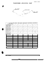
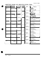
Table
Use the Pricing Table illustrated below as a guide to select and/or verify the desired coin credit setting(s).
/NAME
FRANCE
FRANCE
FRANCE
FRANCE
FRANCE
FRANCE
iFRANCE
FRANCE
‘FRANCE
FRANCE
1 START
1CONTINUE
1CREDrrSlCOlN
tCOlN
1 /COIN2
2
3
4
3
6
7
8
9
io
1,
FRANCE ECA 2
FRANCE ECA 3
FRANCE ECA 4
FRANCE ECA 5
FRANCE ECA 6
FRANCE ECA 7
FRANCE ECA 8
FR4NCE ECA 9
FRANCE ECA :c
FRANCE EC,4 1,
FRANCE ECA 12
AR C T I C THUNDE?
25
COIN 3
lC, O I N 4 1B’LLj
:ml
$%I
OP
OP
w
OP
OP
OD
c
26
M I D W A Y A M U S E M E N T G A M E S , LLC
SERVICE
ARCTIC
THUNDER
CHAPTER
3 SERVICE
SAFETY
INSTRUCTIONS
The following safety instructions apply to operators and service personnel. Read these instructions thoroughly prior to servicing or preparing the game machine for play. Other safety instructions appear
throughout this manual where necessary.
DEFINITIONS OF SAFETY TERMS
l
DANGER lndlcates an imminent hazard. If you fail to avoid this hazard, it WILL cause death or serious
rnjury.
l
WARNING Indicates a potential hazard. If you fail to avoid this hazard, it COULD cause death or serious
injury
* CAUTION indicates a potential hazard. If you fail to avold this hazard, it MAY cause minor or moderate
Injury. CAUTION also alerts :you about unsafe practices.
l
NOTE indicates information of special importance.
I
WARNING: TRANSPORTING GAMES.
The game machine contains glass and fragile electronic devices. Use approprrate care ~
when transporting to avoid rough handling of cabinet. Never move with power switched
on.
WARNING: DISCONNECT POWER.
Always turn power OFF and unplug game machine before attempting service or
lns.talling
or repairing boards with power
adjustments unless otherwise instructed.
b
switched on can damage components and void the warranty.
!
A
!
A
!
A
WARNING: GROUND GAMES.
Avoid electrical shocks! Do not plug in a VGM until you have inspected and properly
grounded it. Only plug this game into a grounded, three-wire outlet. Do not use a
“cheater” plug, or cut off ground pin on line cord.
WARNING: AVOID ELECTRICAL SHOCKS.
The game machine system does not utilize an isolation transformer. Internal cabinet AC
is not isolated from external AC line.
WARNING: HANDLE FLUORESCENT TUBE AND CRT WITH CARE.
If you drop a fluorescent tube or CRT and it breaks, it will implode! Shattered glass can
fly eight feet or more from implosion.
c
2
M IDWAY AMUSEMENTGAMES,
LLC
C HAPTER 3 SERVICE
&
CAUTION: CHECK POWER SELECTOR, LAMP.
Set the 115123OVAC
selector on the power supply for the correct line voltage. Check the
selector setting before switching on game machine. Verify fluorescent lamp assembly is
correct for the local line voltage.
&
Avoid electrical shock! Replacement fuses must be identically rated. Fuse voltage and
current ratings must be identically rated to original fuse.
-I
!
A
~__
Y
!
A
CAUTION: ATTACH CONNECTORS PROPERLY.
Be sure board connectors mate properly. If connectors do not slip on easily, do not force
them. A reversed connector may damage the game machine and void the warranty. Connector keys only allow a connector to fit one set of pins on a board.
CAUTION: USE CARE WHEN SHIPPING HARD DISKS.
The hard disk drive (HDD) must be packed in an anti-static bag. When shipping HDD for
repair or replacement, pack it in an approved container (P/N 08-8068). Do not stack or
drop hard disk drives.
WARNING: HAZARD TO EPILEPTICS.
A very small portion of the population has a condition which may cause them to experience epileptic seizures or have momentary loss of consciousness when viewlng certain
kinds of flashing lights or patterns that are present in our daily environment. These persons may experience seizures while watching some ktnds of television pictures or playing
certain video games. People who have not had any previous seizures may nonetheless
have an undetected epileptic condition.
If you or anyone in your family has experienced sympfoms linked to an epileptic condition
(e.g., seizures or loss of awareness), immediately consult your physician before using
any video games.
We recommend that parents observe their children while they play video games. If you
or your child experience the following symptoms: dizziness, altered vision, eye or muscle
twitching, involuntary movements, loss of awareness, disorientation, or convulsions,
DISCONTINUE USE IMMEDIATELY and consult your physician.
ARCTIC
THUNDER
3
,,
,:‘I,
‘: ‘,,i’/‘I
:,
,,~RVImJG
, ,, ,, ,,,,,, f,f,<Ml
,.(:r”“,‘. :‘I ;r’~onnel should Perform maintenance and repairs. product guidelines apply to ai,
,,,!,, ,:,,, .,J,t.l, rd~~:mnel.
,,,,,,l.ll’~f’,
,,;,l,ll’!’ ‘a .Ind warnings appear throughout the manual where they apply, we recommend
,l,l_* ,111. 1”1’“‘,,
,,,,2,111,/
I’,.” J 1’~ SAFET’{ NOTICES section prior to beginning service,
NOTE: A,~~,,~ scv,tch
,,,,,j y”‘1 ItI”’
,,,,, !,, ,,,, ,, ,,J, dkw before serviong.
~,//,,‘W” “’
, (,< ,,,,, WI, lll/“lf “1 ~lrT’cstant
,, , ,,, ,I)! t 011f1i3” ,,J ~‘ilver
Screws used to fasten controller cover to controller housing and set as,de
enough to expose wiring.
including ground
., ( ,( ,,,,,,~‘,I,II\
llltll”“”
controllerco”er
and set aside until reinstallation,
!, , (), .,I<’ ,lIl~( ““1’ f’w santer hub. Remove
,,,,,,.,1.\11,\1’~‘~’
screws from hub, lift hub from shaft, then set aside until
UII~‘~” the hex nut used to fasten controller housing to motor .=hafi,
1; , (I, .llCl ‘UJLl ”
, , ; ,.,, ~t’*\i‘ll \~(I” I 1,’ II(’ r grip and lift uP and away from dashboard. /fc~nt~~tt~~
hoUs,ng st,cks,
: ,,,,, i ‘!,, ~;.fr’,V. /J *fiC.Y Q’W 0th envise
advance to step 8.
. ,i<t,‘!,t.‘,’
UN fu1’ \ c’n’oved
in step
perform
5. Fasten in place with the screws provided.
/
. , ,\>.,\(,’ lli>\ fb’.15 i k+. This bolt is secured with a retention clip inside of the controller assembly
. ,,,::<\ I I I L~1( ,,I 11111’ .xJd
<.<,,,,.WlA
::
tighten down Until the controller housing begins to lift up and can be removed
, ,;** >,,,t, L’ (l’(‘li ‘1 .?211 to retention clip for future use
n
, ,,.,,zt! .,‘bkv #o+.‘\ ;‘ rniilips head screws used to fasten anti-pinch plate around motor shaft,
~) ,;;, .,\\(\ .: ‘!I /I, ‘j-‘- 3 3ia and set aside with hardware until reinstallation,
. . .\\\’
. .:.. ,,.\I. L.‘.I..
, , \,.‘- I::\ .i \’
:\ >\3$ :.:Tper-resistant
screws used to fasten pod lo cabinet,
-, ,&, .~‘\ * ix\ .” \ . -v 2-d away from cabinet.
,: !%.,\‘
,
1.: i:‘:’ -.ace
.\k\
along with hardware to prevent breakage or loss.
.,.. ~,\ .,..’ \‘.: .‘- r”
, . .&..i.:*
1 -T . :\>x’*c
:qer-resistant screws used to fasten marquee to cabinet,
>\-’ :xlQet to expose opening in cabinet. Store marquee in a safe
: .
, I~8 :\ ~_ >‘sakage 0: loss.
~.: ~*,\b:~ ‘-‘ . I
,
“.) ,>.
. .I:\ .‘.? ” .
t,.2
il
:y
:‘.I?
:,- quipment
place atong with
replacement,
M~M+I~ AMUSEMENT
GAMES. LLC
C HAPTER 3 SERVICE
!
A
WARNING
Fluorescent tubes implode on impact when dropped. Use care in handling.
To service the Fluorescent Light Assembly...
Refer to Marquee Service
illustration.
. Switch off power to game machine and unplug the AC line cord.
. Remove screws used to fasten the clear plastic overlay and mar’quee artwork to marquee.
. Remove both the marquee overlay and artwork and set aside in a safe place to prevent damage.
. Reach up Inside
the opening in cabinet and disconnect the power cable from fluorescent light assembly.
. Loosen, but do not remove the screws fastening assembly to cabinet.
. Slide assembly slightly forward to disengage the keyholes. Lift out the assembly.
l
Perform desired repair or equipment replacement.
MAROUEE
ARCTIC
THUNDER
ILLUSTRATION
5
To service Barrier Panel.. .
Refer to Marquee Service illustration.
. Switch off power to game machine and unplug AC line cord.
l
l
l
Remove Marquee. Refer to setce instfuctions for Marquee
Locate and remove hex nuts used to fasten barrier panel in cabinet. Grasp
edge and lift it out of cabinet.
;-_ I;-+
&ong
bottom
Perform desired repair or equipment replacement
To service B/o wer Fan.. .
Refer to Blower Fan and Speaker Service illustration
l
Switch off power to game machine and unplug AC line cord
l
Remove access panel from atop cabinet
1 .Locate
and remove screws used to fasten access panel to ca;:-et
2,Lift and pivot panel to remove from cabinet. NOTE: This pane’ :: hea\,!
maneuvering during removal and reinstallation.
l
l
b
2,: -s, y:-:re a bit of
Label and disconnect wiring
Remove hex nuts and washers from mounting screws before rers-:qg fa- ;jl- -- - -2’.
Set aslde hardware. Lift out fan assembly.
l
Perform desired repair or equipment replacement.
l
Be sure to clean fan filter, or replace with new one, before re:ns’L,;_ron
ARCTIC
THUNDER
1-3 enclosure
oi :,:*s- z-
7
C HAPTER 3 SERVICE
To service Marquee Mounted Cabinet Speakers.. .
Refer to Blower Fan and Speaker Service
illustration. Speakers are located in the undersrde of ma:q.ree.
l
Switch off power to game machine and unplug AC line cord.
l
Remove fan access panel from atop cabinet
1 .Locate
and remove screws used to fasten access panel.
2 Lift and pi’tioi panei to remove from cabinet. NOTE: Access panel is heavy and may require a b : of
maneuvering during removal and reinstallation.
l
Label and disconnect speaker wiring, including ground strap.
l
Remove hex nuts from mounting screws before removing speakers from enclosure
l
Perform desired repair or equipment replacement.
l
Carefully reseat seals upon completing any task inside speaker enclosure.
l
Reconnect wires, including ground. Refer to the Cabinet Wiring Diagram for correct speaker polarity
NOTE:The speakers are magnetically shielded to prevent video monitor color impurity. Be sure that any
replacement speakers are also magnettcally shielded.
To service Controller.. .
Refer to Controller Service illustration
l
Switch off power to game machine and unplug AC line cord
l
Open rear cabinet door.
l
Label and disconnect all dash wiring including ground strap.
l
Remove confroiler
assembly
1. Remove tamper-resistant screws used to fasten controller cover to controller housing and set aside.
2. Lift up controller cover enough to expose wiring.
3. Label and disconnect all wiring, including ground.
4. Completely remove controller cover and set aside until reinstallation.
S.Locate
and remove center hub. Remove screws from hub, lift hub from shaft, then set aside until
reinstallation.
6.Locate and remove jam nut and lock washer used to fasten controller housing to motor shaft.
7. Grab each controller grip and lift up and away from dashboard. If controller housing St&s, perform
bulleted steps listed below, ofhertvise advance to step 8.
* Replace the hub removed in step 5. Fasten in place with the screws provided.
l
Locate hex-head bolt. This bolt is secured with a retention clip inside of the controller assembly.
Insert bolt in hub and tighten down until the controller housing begins to lift up and can be removed
completely.
l
l
Be sure to return bolt to retention clip for future use.
8.Set aside controller housing with matching hardware until reinstallation.
l
8
Perform desired repair or equipment replacement
MIDWAY AMUSEMENT GAMES, LLC
C HAPTER 3 SERVICE
To service Start and Attack Buttons...
c
Switch off power to game machine and unplug AC line cord
l
Remove controller
l
assembly
I Remove tamper-resistant screws used to fasten controller cover to housing and set aside.
2. Lift up controller cover enough to expose wiring. Label and disconnect all wiring, including ground.
3. Completely remove controller cover.
Perform desired repair or equipment replacement.
l
G ENERAL
DASH
SERVICE
73 service Throttle.. .
Refer to Controller Service illustration.
l
Switch off power to game machine and unplug AC line cord.
l
Open rear cabinet door
l
Label and disconnect all dash wiring, including ground strap.
l
Remove controller assembly
1. Remove tamper-resistant screws used to fasten controller cover to housing and set aside
10
MIDWAY AMUSEMENT GAMES, LLC
C HAPTER 3 SEWCE
To service Throttle (continued)...
2. Lift up controller cover enough to expose wiring. Label and disconnect all wiring, including ground
3. Completely remove controller cover and set aside until reinstallation.
Perform desired repair or equipment replacement.
l
l
Reconnect wires and reinstall. Check for pinched wires
To service Steering Assembly.. .
l
Switch off power to game machine and unplug AC line cord.
l
Unlock and open rear cabinet door.
l
Label and disconnect wiring, including ground strap, for steering assembly.
Remove controller
l
assembly
1. Remove tamper-resistant screws used to fasten controller co’ver
to the housing and set aslde
2. Lift up controller cover enough to expose wiring.
3. Label and disconnect all wiring, including ground
4. Completely remove controller cover and set aside until reinstallation.
5. Locate and remove center hub. Remove screws from hub, lift hub from shaft, then set aside until
reinstallation.
6.Locate and remove jam nut and lock washer used to fasten controller housing to motor shaft.
7. Grab each controller grip and lift up and away from dashboard. If controller housing sticks. perform
bulleted steps listed below, otherwise adwnce to step 8.
l
Replace the hub removed in step 5. Fasten in place with the screws provided.
l
Locate hex-head bolt. This bolt is secured with a retention clip inside of the controller assembly
Insert bolt in hub and tighten down until the controller housing begins to lift up and can be removed
completely.
l
l
Be sure to return bolt to retention clip for future use.
8. Set aside controller housing with matching hardware until reinstallation.
9. Locate and remove Phillips head screws used to fasten the anti-pinch plate around motor shaft.
10. Remove anti-pinch plate and set aside with hardware until reinstallation.
l
Remove dash pod:
1. Locate and remove tamper-resistant screws used to fasten pod to cabinet
2. Gently slide dash pod off of and away from cabinet.
3. Place pod in a safe place along with hardware to prevent breakage or loss
l
l
l
Remove hex nuts used to fasten dash plate to cabinet.
Pull plate forward to expose motor. Lift out Qeering assembly. NOTE: Use caution when removing motor
due to its weight.
Perform desired repair or equipment replacement
ARCTIC THUNDER
11
C HAPTER 3 SERVICE
f
~
A
I
DANGER
High voltage present. Exercise extreme caution while servicing transformer.
To service Transformer.. .
l
Switch off power to game machine and unplug AC line cord
l
Unlock and remove rear door.
l
If power to game machine was only recently disconnected, the transformer may still be warm. Allow
transformer to cool completely before handling.
l
Laibel
and drsconnect all wiring, including ground.
l
Remove screws used to fasten transformer to base of cabinet
l
Perform desrred repair or equipment replacement.
To service Coin Mechanism.. .
l
Switch off power to game machine and unplug the AC line cord
l
Unlock corn door and swing it open.
l
e
l
l
Unlatch and remove each coin me’zhanism separately to clean or replace with a different type. Ensure
mechanism seats fully in the holder upon reinstallation.
Close and lock the release latch, then close the door.
Switch on power to game and change the mechanism setup. then test known good and bad coins to verify ‘operation
To service Coin Counter...
l
Switch oft power to game machine and unplug the AC line cord
l
Unlock and open cash door.
l
Locate meter rn lower left corner of the vault opening. Record meter count before testing or replacement.
0 Locate meter wires. Label and disconnect wiring.
l
l
Remove screws from front bracket.
Perform the desrred repair or equipment replacement. NOTE: Be sure replacement meter has a diode
across the terminals to protect driver circuits.
To service Coin Meter.. .
l
Switch off poiver to game machine and unplug the AC line cord.
l
Unlock and open cash door. Remove cash tubs
l
b
The meter IS located at the bottom of vault on a plate. Remove the screws and lift the plate just enough
to disconnect the meter wires from the harness.
l
Record meter count before testing ‘or replacement.
l
Perform desrred repair or equipment replacement.
ARCTIC THIJNDE?
13
C HAPTER 3 SERVICE
D OLLAR BILL VALIDATOR
SERVKE
To service Dollar Bill Validator...
(Use MARS AE2411 -U3
UL recognized currency changer)
IDollar bill validators or other currency acceptors may be installed in games that are manufactured with an
*additional
wiring connector.
0 Switch off power to game machine and unplug the AC line cord.
0 Unlock and open coin door. Read label affixed to the inside of door for additional information
.’ Disassemble validator and remove material to permit it to fit inside coin door as shown in Dollar Bill l/a/id&or Service illustration, then reassemble unit.
To service Shaker Motor Assembly in Seat...
fqefer
to Seat Service illustration.
* Switch off power to game machine and unplug AC line cord.
l
Remove tamper resistant screws used to fasten seat access panel and pull panel forward
* Label and disconnect wiring, ilicluding ground.
l
Remove hex nuts used to fasten shaker motor to seat and remove
l
Perform desired repair or equipment replacement.
l
Reinstall motor and reattach wiring.
IMPORTANT: Apply removable anaerobic adhesive thread lock (Loctite Blue 242 or equivalent) and
torque each bolt to 20 to 25 in-lbs (177 Nm to 221.25 Nm) if it was loosened.
14
MIDWAY AMUSEMENT GAMES, LLC
C H A P T E R 3 SERVICE
To service Speaker in Seat...
d
Refer to Sear Service
illustration.
Switch off power to game machine and unplug AC line cord.
Remove tamper resistant screws used to fasten seat access panel, and pull panel forxard.
Label and disconnect speaker wiring, including ground.
Remove her nuts used to fasten speaker to seat and remove speaker.
Perform desired repair or equipment replacement.
Reinstall speaker and reattach wirtng, including ground.
IMPORTANT: Apply removable anaerobic adrlesive
thread lock (Loctite Blue 242 or equivaier’
torque each bolt to five to seven in-lbs (44.25 Nm to 62 Nm) if it was loosened.
0
SEAT SERVICE
AR C T I C
T HUNDER
z
CABINET
DECALS
31.3615
BACKLIT MARQUEE
,, ./
: ., ._
31-3625.1
DASH BOARD
SPEEDOMETER DECAL
AR C T I C
T HUNDER
C HAPTER 4 F --7
MONITOR MOUNTING
c
?-%_
-
y-
~-
/
4
.,.
\
‘I
,.
MIDWAY
AMUSEMENT GAMES, LLC
CHSPTER 4 PA R T S
REAR DOOR ASSEMBLY (A-23817)
4108-01219-11
PIN HEAD-WOOD SCREW
#8X1 l/l 5
LOCK RETAINER PLATE
PART OF CAM LOCK ASS.
LOCK PLATE
.i ”
03.7602
VENT COVER 20”
4320-01164.208
.; /BOLT 1,4-20~1-1
01-11291
DOOR BP,ACKr?
f 1.1380
4420.01141-01~
F LANGE
GRIP NL~T
I =h
REAR WOOD DOOR
+
1 4%
PART OF LOCK ASS.
REAR DOOR LOCK ASSEMBLY
,’
.A
/
4420-0114100
FLANGE GRIP Hi,7 15-m
432imllb4.2aB
\
BLACK CARRUG! BOLT 1 4-20x1-1/4
6
MIDWAY
AMUSE?.‘:‘.
3:
C H A P T E R 4 PA R T S
CONTROLLER AND COVER ASSEMBLIES
GREEN PUSH EUTTOM
THUMB THROTTLE LEVER
5014-I
6301-00
POT-SK W/CONN
HEX HEAD BOLT 1!2-13x1-3;4
PUSHBUTTONS
31.3624 (ACTION) RED’
LENS
’
CAP
PLUNGER
;I- SPRtNG
:I
GFSWITCH
HOUSING
,! $.jrNUT
,24.8880
;/BULB
r. -LAMP HOLDER
.r,
;a.
;‘.- MINISWITCH
T HUNDER
31-3616 (START) GREEN
<LEGEND
-/-
ARGTIC
ASSEMBLIES
L_/
, “7
b&- P L U N G E R
‘-7.
.
SPRING
i&T
SWITCH HOUSING
i&r
[-$;-I
,~
,, .? ,-NUT
/-82tif828
O-LAMP HOLDER
.>;
,l
MINISWITCH
11
CHAPTER 4 PARTS
SEAT AND PEDESTAL ASSEMBLY A-23775
04-12950
/-sEAT
4700-00033-006
BLACK FLAT WASHER
265X.750X.067
_”
4701.00005.008
S P L I T L O C K W A S H E R ,:4”
\
--l
4320-01124-448
BOLT 1:4-20x2 314
A-23897
TAIL LIGHT ASSEMBLY
(SEE DETAIL DRAWING)
5555-16059-00
SUBWOOFER SPEAKER 6.5”
J
*
=
4700-00033-008
BLACK FLAT WASHER
.265x.750x.067
.:
4701.00005-008
SPLIT LOCK WASHER l/4”
4406-01128-C
KEPS NUT 6.:
4700-00033.
BLACK FLAT WAS
26:
4701 .I
SPLIT LOCK \
1/4-20x1
04-i 3046
SEAT CABINET
04.
F R O N T SEA1
4008-01100.16
T RESISTANT SCREW-, \
4700-0001 I-OOB
BLACK FLAT WASHER
.172x.437x.059
01-l 5279
REAR ACCESS 7
PANEL
\
‘\
4701.00003~
SL WASHER
-*e-..
-.”
i
\
\
.
e
\
‘1
4700-0001 I .OOB
BLACK FLAT WASHER
.172x.437x.059
01.15289.1
*.’
1
. . .
:
‘..
+------~~~~~~~~NEL
I
BRACKET
-108-01219-11
nnn CPmcw
4108-01219-1 I
WOOD SCREW
4700-00033-008
BLACK FIAT WASHER
.265x.750x.067
.
.r
03-7655-8
CABLE CLAMP li2”
4108-01219-11
W O O D S C R E W #6x11:16
04-l 2874.2
PEDESTAL PLATFORM
12
TAIL LIGHT ASSEMBLY (A-23897)
b
/
A.23839 /
CABLE ASSEMBL Y
SUPPORT BEAM ASSEMBLY
0
4701 -oooo5-008
SPLIT LOCK WASHER 1114
4020.01100-16
TAMPER RESISTANT BOLT
1:4-20x1
4700-00135.008
BLACK FLAT WASHER
265x1.00r065
AR C T I C THLNDER
/
4/fp.7m 100-24
,,,,+.pi<tSlSTAN’
+-&,’ ’ /
CHAP-E= 4 PAX5
COMPUTER
4
ASSEMBLY A-2381 8
LEFT FLOPPY DRIVE
MOUNTING BRACKET
20-7 0556
FLOPPY DRl\lE
4006.01003.066
MACHINE
SCREW&32X3/8
~.
MACHINESCREWy;
*
1
/f
RIGHT FLOPCY DR:, I
MOUNTING BR&-‘(ii
A.23901
4006-01003-068
MACHINE SCREW
HARD DRIVE
01-l 5290
ti;i~fE~VE
COMPUTER PARTS NOT SHOWN:
H-23936 WATCHDOG CABLE
20-10720 AGP VIDEO VOODOO 3
20-10741 ETHERNET ADAPT
5795-16512-09 RIBBON CABLE 34 PIN
5795-11654 ,-1, RIBBON CABLE BOCOND 40 PIN
579516549-1, RIBBON CABLE 40COND 40 PIN
-\
L-
\
20-l 0738
FAN
20-l 0726
POWER SUPPLY
ARCTIC MOTHER BOARD
MOTHER
20-10740-02
’ 1’
LITHIUM BAlTERY
ARCTIC
THUNDER
E,23uNT :
C HAPTER 4 PARTS
WHEEL DRIVER BOARD ASSEMBLY 04-12770.1
,
Field
Replaceable
DESIGNATIOI u
Parts
1PART NUMBER
FUNCTION
DESCRIPTION
~ 01
1
5 1 6 2-08976-00
1
Darlington
2N6427
) Q2
I
(33
) 5 2 5O-l 5624-00
78Ll5
Voltage regulator
/
/ 5250-156%00 Volt: m _ e_
reaulator I 79Ll5
D2, D3
5070-I
D5
507~1511Er00
Diode
MUR1605
5731-I
Fuse
4ASB, 125V, 5xZOmm
F1,FZ
6272-00
4094-00
Diode
Fast Fe6535ns
.63A FB
i F3
5731-15627-00
U5
/ 5370-14069-00
Driver
) BRI
I 5100-13945-01
Rectifier
1 u1.u2
5370-12602-00
Pre-Driver
18
Fuse
Power
Bridge
LM12 Op Amplifier
IOOV, 6A, SIP
ULN2064B
IC
MIDWAY AMUSEMENT GAMES. LLC
C H A P T E R 4 PA R T S
POWER HYDRO FILTER BOARD ASSEMBLY 04-12651-l
Field
Replaceable
Parts
PART NUMBER
FUNCTION
/ DESCRIPTION
5060-l
EMI
Filter
i 2200 pF Dual Capacitor
EMI
Filter
Ferrite Bead Inductor
5633-00
5556-14181-00
IDE EXPANSION FILTER BOARD 04-12826
No Field Replaceable Parts
AR C T I C
T HUNDER
19
C HAPTER 4 PARTS
QUAD HIGH CURRENT DRIVER BOARD 04-13068.2
5.
__
_*_
-’
Field
20
Replaceable
Parts
MIDWAY
AMUSEMENT GAMES, UC
C HAPTER 4 PARTS
LINE CORD APPLICATION CHART
COIN DOOR APPLICATION CHART
22
MIDWAY AMUSEMENT GAMES, LLC
CHAPTER
TRANSFORMER
APPLICATION
LINE
VOLTAGE
CONNECTOR
4 PARTS
CHART
TRANSFORMER
C”
$
/-
,*;;
,Z’
‘--.
“\
‘1
-<,,
ic_-s- /
LOW
VOLTAGE
CONNECTOR
230 VAC Hungary
230 VAC Italy
.
.
100 VAC Japan
.
.
110 VAC Japan
230 VAC New Zealand
230 VAC Norway
230 VAC Spain
.
,
I
.
230 VAC Switzerland
230 VAC Uk
120 VAC United States
.
110 VAC United States
ARCTIC
.
.
I
.
23
THUNDER
-
,,I,1
I
W IRING
ARCTIC
THUNDER
f
C HAPTER 5 W IRING
Main Cabinet Wiring
2
MIDWAY AMUSEMENT
GAME
C HAPTER 5 WIRING
SUBSTITUTE BOARD LED INDICATOR STATUS TABLE
~Designation
Location
D 28
Near fuse F2 &
JP15 connector
D 25
Near fuse Fl
Color
Function
Red
Indicator
-
Indicator
D 24
Near U5
Indicator
D 23
Near U5
Indicator
D 22
Near U5
D 21
Near U5
D 17
No +5V
+5V Present
Intermittent +12V
Red
I
c
Red
+f2V Present
intermittent +I 2V
d
Not In use
Cammumcation e r r o r
Normal operation
Red
Not in use
EEPROM Not Responding !
Normal operation
Red
Not in use
Security error
Normal operation
Indicator
Red
Not in use
Board reset
Normal operation
Near U5
Indicator
Green
D 18
Near U5
__Indicator
Green
D 14
Near U5
__Indicator
Green
D 20
Near U5
Indicator
Green
Not in use
Faulty Board
Normal operation
D 26
Near JP9
Indicator
Red
No power
+5V present
Intermittent power
ARCTIC
THUNDER
-__Indicator
I
Faulty Board
Faulty Board
/
!
5
C HAPTER 5 WIRING
AUDIO AMPLIFIER LED INDICATOR TABLE
Designation
LED 1
Location
Upper Center
Nearest C3
Wl)
State
Function
Fault Indicator
/
Red
Blinking
LED 2
Lower Center
Near U2 & U6
VW
Fault Indicator
/
Meaning
Overload (note 2)
I
Red
Notes:
1. Active output protection circuit. To reset circuit, clear fault and switch off power.
2.
Blinking caused by either intermittent audio overload or overheating. LED is only supposed to blink
during start-up.
WHEEL DRIVER LED INDICATOR TABLE
Designation
Location
i
Function
Color
State
Meaning
1
I Indicator
Right Center
Nearest C5 & P2
LED 1
Notes:
1. The regulated power supply voltage source is monitored by LED 1, which should remain lit non-stop
Blinking or failure to illuminate indicates an intermittent connection, power problem, circuit fault, etc.
ARCTIC
THUNDER
6
TROUBLESHOOTING
l
l
l
l
l
Before servicing electronics, turn off AC power to the VGM. Wait for capacitors to discharge.
Before touching or handling electronic assemblies, discharge static electricity on your body. To discharge static, begin by connecting the line cord to a properly grounded outlet, but do not turn on the
power! Next, touch the safety ground stud of the power supply chassis.
Store electronic assemblies in an anti-static area. Use anti-static bags to store or transport circuit
boards, Transport the hard drive in original shipping container.
Do not remove or connect electronic assemblies when the power to the cabinet is switched on. Otherwise you’ll damage electronic assemblies and void the warranty.
Replace ground wires, shields, safety covers, etc., upon completion of maintenance or service. install
and firmly tighten all ground and mounting screws.
ARCTIC
THUNDER
COIN MECHANISM AND PRICING TROUBLESHOOTING
Symptom
l
Cause
Video Game Machine
(VGM) accepts currency or tokens, but
number of credrts per
coin or bill is incorrect
Improper settings
at Pricing Menu
Access Diagnostic Menu, then select SWITCH
TEST. Conduct test to confirm operation of game
swatches.
Access Pricing Menu, then select one of the available pricing options to verify settings.
Faulty wiring
1.
2.
Confirm cabinet wiring is correct for this game.
Assure coin meter and coin switches connect
properly to control input wires.
Improper currency
1.
Unlock and open cash door. Empty cash box and
inspect revenue for counterfeit currency.
Check vault. Remove any items that block mechanism’s path.
2.
Faulty coin mechanism
1. Unlock and open coin door. Check each mechanism for proper mounting.
. Remove mechanism.
l
Clear currency path.
l
Reinstall mechanism and close latch.
Tilted coin mechanism or game
1.
2.
Burned-out bulb
1.
1 Audio and video are
present.
b Coin indicators do not
light
1.
2.
k VGM will not accept
currency or tokens.
k VGM WII not enter
play mode.
Required Action
Verify mechanism is level after doors close.
Repair or replace coin door if it IS bent or damaged.
3. If necessary. adjust cabinet leg levelers to keep
mechanisms level.
2.
Open fuse circuit
Burned-out bulbs may appear white or darkened.
*Replace burned-out bulb with one identically
rated.
Check continuity with digital voltmeter.
1. Check fuse continuity with digital voltmeter.
2. If fuse is blown. replace fuse with an identically
rated part.
3 . If fuse isn’t blown, check wiring.
CAUTION
Do not remove or install any connector when power is turned on. Installation under power will
damage the circuit boards, ROM’s or hard disk and void the warranty.
TROUBLESHOOTING
2
M I D W A Y AM U S E M E N T G A M E S , L L C
1
/
‘0
START UP TROUBLESHOOTING
r-
T
Symptom
l
l
Video Game Machine
(VGM) does not start
$
I
T
Cause
-______
Power problem
Required Action
1.
2.
VGM appears completely non-functional.
3.
Check power is switched on.
Make sure fans in Arcade Computer are turning. /f
not: Is the power supply connected to its power
cable? Is power supply turned on?
Plug cord into AC power outlet. Verify presence of
AC line voltage.
l
No audio
No illumination
Improper line voltage switch setting
1.
l
Turn off power. Unplug AC line cord. Check line
voltage switch. If necessary, set it to agree with
local AC line voltage. Retest game.
No video display
Open fuse
I.
Turn off power. Examine fuse on power chassis.
cabinet wall or electronic equipment shelf.
l Replace faulty fuses wrth
identically rated parts.
l
Turn on game power. If fuse opens again,
check wiring harness and connectors.
l
t
i
Faulty wiring
0
l
l
l
Vrdeo Game Machine
(VGM) does not start.
t
1.
Remove Ime cord. Test line cord, power plug, and
IEC connector for breaks or damage.
l Verify continuity of each wire in cord.
l
Install cord on power chassis.
l Press connector firmly to seat it.
/ 2. Assure that cabinet wiring harness connectors
fully seat in corresponding power supply and
I
board connectors.
3. Inspect wiring for breaks or damage.
L
Faulty coin rnechanism
1.
VGM accepts currency or tokens.
2.
Audio and video are
present.
3.
4.
Faulty switches
ARCT c TH U N D E R
4
Unlock and open coin door.
l
Check each currency acceptor to assure proper
mounting.
l
Verify each release latch is closed and locked.
Test mechanism with good and bad coins to see if
mechanism accepts and rejects currency correctly.
Inspect to see if external acceptor indicators (Pricing, Flashing Arrows, etc.) are lit.
Verify each acceptor operates properly by placing
it in working game. Replace bad parts.
1.
Access Diagnostic Menu, then select SWITCH
TESTS. Conduct test to confirm operation of each
switch.
2. Assure no loose parts or wires are caught in
switch contacts.
3. Check for continuity in each suspect switch connection (Common to Normally Open or Common
to Normally Closed).
4 . Replace faulty switches (bent levers, broken actuators, etc.).
TROUBLESHOOTING - 3
Sylllpt0m
* Video Game Machine
(VGM) does not start.
~
Cause
1R e q u i r e d
___Faulty wiring
~ 1.
2.
D VGM accepts currency or tokens.
l
Audio and video are
present.
b Video Game Machine
(VGM) appears nonfunctional.
Assure no wires are caught in hinges, latches or
switch contacts.
Check wiring continuity from circuit board connectors to acceptors.
Power problem
Inspect circuit boards under low-light conditions
l
The LED’s glow and the fan turns when processor circuits receive voltage and indicate presence of DC from power supply. However.
voltages or signals may not be normal.
Switch on power to game machine and measure
DC voltage settings. Refer to the Cabinet Wiring
Diagram for specific wiring information and voltage limits.
l Set the digital voltmeter to the 20-volt DC setting and measure the power connector pins.
Adjust the +5V source if necessary.
l Set the digital voltmeter to the 2-volt AC setting
and measure DC voltages at power connector
pins. Any reading here indicates that supply
voltages are unstable and may contain ripple or
noise.
Faulty wiring
Switch off power to game. Check both wiring harness connectors and other types of connectors to
make sure they fully seat onto mating board connectors.
Faulty circuit
boards or Arcade
Computer
Run power-up self-test sequence. Note errors or
failures during test.
Switch off power to Arcade Computer, but NOT
the game machine. Wait for HDD to stop spinning,
then loosen the thumbscrews on computer cover
and remove. Listen for beeping sounds.
1 Currency acceptor
price indicator is illuminated.
T R O U B L E S H O O T I NG - 4
A c t i o n
M I D W A Y AM U S E M E N T G A M E S . LLC
I
LINKING
PROBLEM
Symptom
l
l
l
Cannot connect multiple Video Game
Machines (VGMs)
together
VGM does not recognize other players in
linking operation
TROUBLESHOOTING
Cause
Required Action
Faulty wiring
1.
Install required crossover between cabinets. Each
coupler connects two VGMs (one pair). Do not use
standard telephone type couplers or wiring for linking.
2. Use only 10 Base-T, Ethernet-type. Category 5.
twisted-pair wiring.
3. Do not overextend linking cables supplied with
VGM.
Improper llnking
hardware
1.
Use required network hub for your local network.
A Hub Link Kit permits up to four VGM connections. Array completion requires basic kit brackets
and spacers.
Improper
1.
Record any error messages that occur during selftest.
Check that each VGM has a unique ID number.
Access the Diagnostic menu, then select LINKING
TEST. Confirm the link is enabled.
settings
~
VGM functions normally by itself
LL
2.
3.
Verify the hub receives power. AC adapter wires
1. Inspect hub Indicator lights.
l
Illuminated indicator lights for each active port
light up if the cable(s) are properly connected.
l Check for cable continuity from hub to VGM for
each indicator that failed to light.
2 . Assure no loose wires are caught in hinges, doors
or under cabinet.
3. Verify linking cable connects to CPU Board for
each game.
4. Verify
each linking cable operates properly by
placing it in a working game.
CAUTION
Do not remove or install any connector when the power is turned on. Installation under power
will damage the circuit boards, ROM’s or hard disk drive and void the warranty.
ARCTIC
THUNDER
TROUBLESHOOTING
-
5
LINKING
PROBLEM
L Symptom
r;b Some Video
Game
Machines (VGMs) in
group link properly,
while others do not
TROUBLESHOOTING
Required Action
Improper hub
switch setting
1. Assure switches on hub are set according to kit
I
instructions. (VGMs on a network do not require
~
couplers. Hub has electronic crossover.i
2. Inspect hub indicator lights for llnk activity. See
manufacturer’s literature for diagnostics.
Wrong software
version
1.
Faulty wiring
(2 VGMs)
1.
2.
Faulty wiring
(3 or more VGMs)
1.
2.
3.
-:
Verify all linked VGMs use same software version.
Machines with different versions will not recognize
each other. Contact your distributor for a software 1
update if needed.
1
Insert only the supplied crossover connection
between coupled VGMs. Standard couplers
appear identical to devices supplied with games,
but do not include an internal crossover.
Verify each linking crossover coupler operates
properly by placing it in a working link between two
VGMs.
Use an additional crossover connector and cable
to extend game or hub link connection. Two crossovers cancel each other out and results in same
problem as no link crossover.
Connect cables directly to hub. Do not use a
crossover coupler and hub together in single network.
Separate communications wiring from other wiring. Wires that must cross can only cross at right
angles to limit noise pickup.
CAUTION
Do not remove or install any connector when power is turned on. Installation under power will
damage the circuit boards, ROM’s or hard disk drive and void the warranty.
TROUBLESHOOTING
-
6
I
Cause
MIDWAY AMUSEMENT G~MEZ,
LLC
PLAYER
CONTROL
TROUBLESHOOTING
7
Symptom
Cause
11Intermittent or completely non-functional
player controls
Faulty switches or
lamps
Required Action
1) Video Game Machine
(VGM) starts normally.
5.
6.
Check for wires caught in door hinges, latches, or
switch contacts.
2. Verify harness connectors are attached and fully
seated.
j 3. Assure control switches connect properly to con/
trol input wires.
Check cabinet wiring is correct for this VGM.
I 4.
’
Faulty switch w8 rn9
1 Steering pulls to one
side
No
wheel
feedback
Steering does not aim
vehicle as expected
-a&y Wheel
Iriver Board
mproperly set
:alibration
-a&y circuit
Iaulty motor
Access the Diagnostic Menu, then select SWITCH
TEST. Conduct test to confirm switch operation.
Access Diagnostic Menu. then select LAMP TEST.
Conduct test to conflrm lamp operation.
Check for loose parts or wires caught in switch
contacts.
Check continuity at each switch connection (Common to Normally Open or Common to Normally
Closed).
Verify player control operates properly by placing it
in working VGM.
Verify light bulbs used for dashboard switches are
type specified in parts listing. Other types will light.
but may produce too much heat. Excess heat may
cause switches to bind.
1/
1.
1.
2.
1.
i
Access the Diagnostic Menu, then select CALIBRATE FEEDBACK. Perform the calibration
sequence.
Locate power amp on Wheel Driver Board’s large
heatsink. Test Board and replace bad part or
board if necessary.
Access Diagnostic Menu, then select CONTROLLER TEST. Select and perform one of the test
sequences to aid in correcting calibration.
1.
2.
Examine fuses and cables on Wheel Driver Board.
Check cables and wiring between Arcade Computer, interface board, wheel driver and motor.
3. Replace bad parts.
1.
Inspect motor. Refer to the Steering Assembly
Service instructions in Chapter 3 for complete
details.
ARCTIC
THUNDER
TROUBLESHOOTING
-
7
Symptom
l
l
l
Cause
Sloppy, unpredictable
or ineffective steering
Blocked or faulty
fan
Video IS present
--
Video Game Machine
(VGM) operates normally
Faulty mechanical parts
Required Action
__.~
1.
Fan located on power supply acts as an exhaust
fan; with power switched on, check fan airflow to
assure that nothing blocks airflow.
1,
Inspect motor for faulty or worn belts, bearings,
couplings, gears, etc. Refer to the Steering
Assembly Service instructions in Chapter 3 for
complete details.
1
Inspect Wheel Driver Board under low-light conditions. To indicate presence of AC from the transformer the LED’s glow when voltage is recerved.
However, voltages or signals may not be normal.
Examtne fuses and cables on Wheel Driver Board.
Replace bad fuses.
Use drgital voltmeter to verify AC voltage between
each fuse holder and ground. Measure approxrmately 25V. See Wiring Diagram.
Use the 20-VAC setting on digital voltmeter to
measure DC voltage at motor. Do not move steering wheel, drive belt, or motor while making this
measurement. Any reading indicates unstable
supply that may contain ripple or noise.
Select CONTROLLER TEST from the Diagnostic
Menu. Follow on-screen instructions to verify
operation of the wheel motor and steering position
sensor.
Verify proper operatron of Wheel Driver Board by
placing it in working VGM.
-~
Faulty Wheel
Driver Board
5.
6.
-0ose or worn
irive be/t
1.
2.
Inspect motor for faulty or worn belts, bearings,
couplings, gears, etc. Refer to the Steering
Assembly Service instructions in Chapter 3 for
complete details.
If drive belt isn’t worn or damaged, check its tightness.
WARNING
The Wheel Driver Board heatsink, power resistors, and other components may be very hot.
The DC Motor in the steering wheel may also be hot.
TROUBLESHOOTING -
8
MIDWAY AMUSEMENT GAMES, LLC
I
/
~
VIDEO TROUBLESHOOTlNG
Symptom
l
l
l
1 Cause
Monitor appears nonfunctional
.Audio
is present
Power problem
Required Action
1.
,
Video Game Machine
(VGM) controls operate normally
1.
Switch off power. Verify that video signal and
Remote Adjustment Board connectors seat properly on Video Monitor Board.
2 . Assure that video cables connect to circuit boards
and Arcade Computer.
3. Assure that no wires are caught on chassis or
mounting brackets.
Improper monitor
adlustments
t Faulty monitor cir-
1.
Try setting Brightness and Contrast above mini-
1.
Check AC line for a blown fuse on Video Monitor
Board. Replacement fuses must be identically
rated.
If the fuse is good, verify video monitor operates
correctly by placing it in a working VGM.
If monitor is bad; Check monitor power supply.
If the power supply is good, Check monitor bon
zontal output transistor and related circuitry.
cultiy
2.
3.
4.
l
l
l
Graphic images from
game do not appear
c
Improper components
No audio
Power-up self-test
runs
I.
2.
l
White areas at screen
edges appear tinged
with color
Dots at screen edges
appear ovoid or cylindrical
ARCTIC
THUNDER
Verify circuit boards are correct for this game.
Labels on each board record manufacturers’
name, assembly number and hardware version.
Verify HDD is correct for this game. Label on HDC
records assembly number and software version.
Hard Disk Drive
(HDD) problems
1.
Allow game to load normally. Note and record any
error messages that occur during self-test.
Power Problems
1.
Turn on Power. Use 20-volt DC setting on digital
voltmeter to measure DC voltages present at
Power connector pins. Verify +5V source if it is
adjustable. Refer to Cabinet Wiring Diagram for
specific wiring information and voltage limits.
Use Z-Volt AC setting on digital voltmeter to mea
sure DC voltages at Power Connector pins. An:
reading indicates the supply voltages are unstable
and may contain ripple or noise.
2.
l
Verrfy connection of AC Power to video monrtor.
Inspect neck of CRT in dim light. Glowing filament
near CRT base confirms monitor circurts
receive
nn~~r
r” II _.,Hnwavnr
._ -. _ , voltages or signals may not be
normal.
Picture tube
dynamic convergence is out O f
alignment
1.
Have service bureau dynamrcally re-converge
monitor. This procedure requires removing and
repositioning yoke. Service bureau must follow
instructions from monitor manufacturer.
TROUBLESHOOTING 9
Symptom
l
l
l
Video images tear or
roll, or have black bar
down middle of screen
Missing colors
One color is dimmer or
brighter than others
Cause
Required Action
Faulty wiring
1.
Check connectors and cables between c:rc
boards and monitor for wiring continuity.
2. Assure connection of all cabrnet grounc
especrally at video monrtor chassrs.
Faulty monitor circuitry
1.
Verify video monitor operates correctly by :
nectrng it to workrng game macnrne
2. Assure video monitor is correct type forth L
Video monitors with wrong resolu:ron c;;sync.
Improper sync
signals
I.
2.
Make sure Video Board emrts proper type :
Verify jumpers are set correctly for monito-
Electromagnetic
fields
1.
Move game cabinet further away from macappliances, or other video games.
Faulty wiring
1.
Check connectors and cables for wiring co
from circuit boards to video monitor.
Faulty monitor
color drive circuitry
I.
Verify video monitor operates correctly by : _
netting it to a working game machine.
Maladjusted color
bias pots
1.
Access Diagnostic Menu. then select MONr‘
TEST. Perform the COLOR BARS TEST
l
Adjust three bias pots for best colors. if.?
monitor neck boards include these pots.;
Check White Screen. Touch up controls.
l If whites still seem tinted, have service t:
rejuvenate picture tube.
. Whites appear tinted
everywhere on screen
l
Picture is too narrow
2.
Maladjusted
pot.
WIDTH
I.
2.
l
l
l
Access Diagnostic Menu, then select MOl\i:TEST. Perform CROSSHATCH TEST.
Adjust screen width using the w&h pot on r
Remote Control Board. located benind corr
Picture is too short
Maladjusted
HEIGHT pot or
damaged vertical
circuit
1.
Access Dragnostic Menu, then select MON
TEST. Perform CROSSHATCH TEST.
l
Adjust screen height usrng tne height po!
Monitor Remote Control Board behind coir
l If pot has no effect, service verrcal outpLcuit.
Picture seems shifted
to one side
Maladjusted
HORIZONTAL
POSITION pot
1.
Access Diagnostic Test, then select MONIT-Y
TEST. Perform CROSSHATCH TEST.
l
Adjust Horizontal Posrtron
pot for best pi:
using the Monitor Remote Control Board be
coin door.
Keystone-shaped picture
Shorted turns in
yoke
1. Substitute working yoke.
2. Have service bureau converge monitor.
3. Retest monitor.
T R O U B L E S H O O T I NG - 1 0
M I D W A Y AM U S E M E N T GA+:
I
AUDIO
l
l
,
j
TROUBLESHOOTING
Cause
Required Action
Improper volume
setting
1.
Video is present
Video Game Machine
(VGM) appears to
operate normally
Audio is distorted,
muffled or has missing
frequencies.
I
l
2.
Faulty wiring
1.
Faulty or
obstructed
speaker
1.
2.
Faulty Audio
Board
1.
Power Problems
1.
Faulty or improper
speaker
1.
2.
___Faulty wiring
I
.~___
Access Main Menu, then select VOLUME LEVEL.
Make sure Attract Mode Music is enabled.
I
Verify a//volume levels are properly set well above i
zero. If necessary, change volume levels to make
game audible.
1
Switch off power to game machine. Check wiring
harness connectrons attach and fully seat onto
mating board connectors.
l
Verify harness connects to CPU Board.
I:
l
Check audio cable connectors in same way.
Remove speaker grilles and inspect speakers.
Clear loose parts and wires from magnets, mounti
ing screws, terminals, and speaker cones.
Verify proper operation of Audio Board by placing
it in a working game machine.
I
Use 20.volt DC setting on digital voltmeter to measure DC voltages present at Power connector
I
pins. Verify +5V, -5V and +12V sources. Refer to
Cabinet Wiring Diagram for specrfic
wiring information and voltage limits.
Switch off power to game machine.
l
Remove speaker grilles and inspect speake-s
l Verify speakers are full range (700 lo 10.000 hz
response) and rated for at least 20 watts. Woof- /
ers must be rated for at least 40 watts.
Verify
p r o p e r s p e a k e r o p e r a t i o n b y plac!ng
speaker in question in a working game machine.
,
1. Multiple-speaker installations: Check for reversed
speaker wiring. Weak or low frequencies and thin
or hollow sound quality are symptoms of incorrectly phased speakers.
1
I
*Sound tests may not detect this condition. but
you can hear it during operation.
1. Access Diagnostic Menu, then select Speaker
Test. Perform one or several of the available tests
1 l Dead sound channel
2.
Faulty wiring
lj 0
2.
3.
i
ARCTIC
1.
THUNDER
Verify
proper speaker operation by connecting
speaker in question to working game machine.
Verify cabinet wiring is correct. Check audio wrrinT\
connectron to speakers.
Check audio cable connection is fully seated.
Check for broken or shorted wares.
I
/
TROUBLESHOOTI~VG
- 13
WARNINGS & NOTICES
WARNING
tJse of non-MIDWAY parts or circuit modifications may cause serious Injury or equipment damage’
’ Use only MIDWAY authorized components and parls. Failure to do so will void your warranty and may result in
incorrect
or unsafe operation
Substitute pa-is or modifications
may void the EMC dlrectlve
or FCC type acceptance.
*’ Federal copyright. trademark and patent 1av.s protect this Video Game Machine (VGM). Unauthorized
modifications
may be illegal under Federal law. The mooification
ban also applies to Mrdway Amusement Games, LLC and VGM
logos, designs, publlcatlons
and assemblies.
Moreover. farxmiles of MIDWAY equrpment
(or any feature thereof)
may be illegal under federal law, regardless oi whether or not such facslmlles
are manufactured with Midway
Amusement Games, LLC components.
WARNING
Prevent shock hazard and assure proper VGM operation.
Plug this VGM Into a properly grounded outlet. Do not use a
cheater plug to defeat the power cord’s grounding pin. Do not cut off the ground pin.
WARNING
,4 very small portion of the population has a condition
which may cause epileptic
seizures or momentary loss of consciousness when viewlng certain kinds of flashirg
lights or patterns that are present In our daily envrronment.
These
persons may experience seizures while watching
some kinds of television
pictures
or playing certain video games.
IPeople who have not had any previous seizures may nonetheless have an undetected epileptic conditron.
If you or anyone I” your family has experienced symptoms l nked to an epileptic condrtion
(awareness), Immediately consult your physician before using any video games.
(e.g. seizures or loss of
We recommend that parents observe their children
while they play vtdeo games. If you or your child experience the followmg symptoms: dizrlness.
altered vision, eye or muscle twitching, involuntary movements. loss of awareness, disori~entation. or convulsions,
discontmue use !mm&atelyand consult your physician.
(CAUTION
lnformatron
in this manual is subject to change without
no!lce. MIDWAY reserves the right to make Improvements in
equipment function, design, or components as progress in engrneenng
or manufacturing warrants.
‘COPYRIGHT & TRADEMARK NOTICE
You may not reproduce any part of this publicatr3n
by mechanical, photographic, or electronic means. You may not
prepare phonograph recordings of this document. You may not transmit this publication or otherwise copy it for public
or private use, wlthout permission from the publisher.
Entire contents of this manual copyright 02000 Midway Amusement Games LLC. All rights reserved. MidwayB
A r c t i c ThundeP are trademarks of Midway Amusement Games LLC.
and
NOTICE
This equipment generated. uses and can radiate radio frequency energy and if not installed and used in accordance
with the i n s t r u c t i o n manual, may cause harmful Interferance
to radio communications.
Operatton
of this equipment in a
residential area I S likely to cause harmful interiorence
in which case the userwill be required to correct the Interference
at his own expense.
NOTICE
When MIdway Amusement Games, LLC ships a VGM, it compiles with FCC regulations. Your label is proof of cornpI,ante. Legal repercussrons
to the owner or drstn%Xor
may result if the label is missmg or damaged. If your VGM does
not contain an FCC complrance
label, call Midway Amusement Games, LLC immediately.
For Serwce:Call
your authorized Midway Amusement Games, LLC dlstnbutor.
MIDWAY AMUSEMENT GAMES, LLC
3401 N. C ALIFORNIA AVE . C HICAGO, I LLINOIS 60618-5899 USA
Visit our Web site at hffpYhww.midway.com
6
Entire contents of th1.s manual copyright
0 2000 M~vwnv
A MUSEMEN T G AMES , LLC All rights reserved.